1
CHAPTER
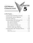
GS1 MODBUS
COMMUNICATIONS
5
Contents of this Chapter...
Communication Parameters Summary . . . . . . . . . . . . . . . . . . . . .5–2
GS1 Parameter Memory Addresses . . . . . . . . . . . . . . . . . . . . . . . .5–4
GS1 Status Addresses . . . . . . . . . . . . . . . . . . . . . . . . . . . . . . . . . .5–8
Communicating with AutomationDirect PLCs . . . . . . . . . . . . . . .5–11
Step 1: Choose the Appropriate CPU . . . . . . . . . . . . . . . . . . . . . . . . .5–11
Step 2: Make the Connections . . . . . . . . . . . . . . . . . . . . . . . . . . . . . .5–11
GS1 RS-485 Serial Comm Port . . . . . . . . . . . . . . . . . . . . . . . . . . . . . . . . . . . .5–11
RS-485 Connections For Multiple Drives . . . . . . . . . . . . . . . . . . . . . . . . . . . . .5–12
RS-232C to RS-485 Conversion . . . . . . . . . . . . . . . . . . . . . . . . . . . . . . . . . . . .5–13
Ethernet Connection using GS-EDRV . . . . . . . . . . . . . . . . . . . . . . . . . . . . . . .5–15
Step 3: Set AC Drive Parameters . . . . . . . . . . . . . . . . . . . . . . . . . . . . .5–16
Step 4: Configure the PLC CPU . . . . . . . . . . . . . . . . . . . . . . . . . . . . .5–16
Configure the CLICK PLC . . . . . . . . . . . . . . . . . . . . . . . . . . . . . . . . . . . . . . . .5–16
Configure the DirectLOGIC CPUs . . . . . . . . . . . . . . . . . . . . . . . . . . . . . . . . . .5–18
CLICK Modbus Ladder Programming . . . . . . . . . . . . . . . . . . . . .5–20
Separate Run Command Write Instruction . . . . . . . . . . . . . . . . . . . . . .5–20
Block Transfer Parameters for Modbus Programs . . . . . . . . . . . . . . . . .5–20
CLICK Communication Program – (for CLICK PLCs) . . . . . . . . . . . . . . .5–21
(Table of Contents continued next page)
5–1a
Chapter 5: GS1 Modbus Communications
Contents of this Chapter (continued from previous page)...
DirectLOGIC Modbus Ladder Programming . . . . . . . . . . . . . . . .5–35
Separate Run Command Write Instruction . . . . . . . . . . . . . . . . . . . . . .5–35
Block Transfer Parameters for Modbus Programs . . . . . . . . . . . . . . . . .5–35
DirectLOGIC Basic Communication Program – start with this code . . .5–36
Programming Differences for DirectLOGIC PLCs . . . . . . . . . . . . . . . . . .5–37
RX/WX Instructions for DL05, D2-250(-1), D4-450 . . . . . . . . . . . . . . . . . . . . .5–37
MRX/MWX Instructions for DL06, D2-260 . . . . . . . . . . . . . . . . . . . . . . . . . . .5–37
DL MRX/MWX Communication Program – for DL06 & D2-260 PLCs .5–38
DL RX/WX Communication Program – for DL05, D2-250(-1), D4-450 5–51
Communicating with Third-Party Devices . . . . . . . . . . . . . . . . . .5–64
Common Third-Party MODBUS RTU Masters . . . . . . . . . . . . . . . . . . . .5–64
Using Modbus ASCII . . . . . . . . . . . . . . . . . . . . . . . . . . . . . . . . . . . . . .5–65
Data Format . . . . . . . . . . . . . . . . . . . . . . . . . . . . . . . . . . . . . . . . . . . . . . . . . .5–65
Communication Protocol . . . . . . . . . . . . . . . . . . . . . . . . . . . . . . . . . . . . . . . .5–66
Comm Delay – Optimizing Communications . . . . . . . . . . . . . . .5–71
Optimizing Communications to GS Drives . . . . . . . . . . . . . . . . . . . . . .5–71
Types of Messages Sent to GS Drives . . . . . . . . . . . . . . . . . . . . . . . . . .5–72
Format of “Read Registers” Messages: . . . . . . . . . . . . . . . . . . . . . . . . . . . . . .5–72
Format of “Write Multiple Registers” Messages: . . . . . . . . . . . . . . . . . . . . . . .5–72
Format of “Write Single Register” Messages: . . . . . . . . . . . . . . . . . . . . . . . . .5–72
Example Message: . . . . . . . . . . . . . . . . . . . . . . . . . . . . . . . . . . . . . . . . . . . . .5–72
Additional Message Delay Times . . . . . . . . . . . . . . . . . . . . . . . . . . . . .5–73
Modbus-specified Delays Between Messages . . . . . . . . . . . . . . . . . . . . . . . . .5–73
Other Delays . . . . . . . . . . . . . . . . . . . . . . . . . . . . . . . . . . . . . . . . . . . . . . . . . .5–74
Communication Delay Timing Diagram . . . . . . . . . . . . . . . . . . . . . . . . . . . . .5–74
Communication Delay Summary . . . . . . . . . . . . . . . . . . . . . . . . . . . . .5–75
5–1b
GS1 Series AC Drive User Manual
2nd Edition
07/06/2011
Chapter 5: GS1 Modbus Communications
2nd Edition
07/06/2011
GS1 Series AC Drive User Manual
5–1c
Chapter 5: GS1 Modbus Communications
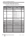
Communication Parameters Summary
A summary of the GS1 Communications Parameters is listed below. For a
complete listing of the GS1 Parameters, refer to CHAPTER 4.
Communications Parameter Summary
GS1
Parameter
P9.00
Description
Range
Default
Communication Address
1 to 254
1
P9.01
Transmission Speed
P9.02
Communication Protocol
P9.03
Transmission Fault Treatment
P9.04
Time Out Detection
P9.05
Time Out Duration
쏆 P9.07
Parameter Lock
P9.08
Restore to Default
Block Transfer Parameter 1
쏆 P9.11
Block Transfer Parameter 2
쏆 P9.12
Block Transfer Parameter 3
쏆 P9.13
Block Transfer Parameter 4
쏆 P9.14
Block Transfer Parameter 5
쏆 P9.15
Block Transfer Parameter 6
쏆 P9.16
Block Transfer Parameter 7
쏆 P9.17
Block Transfer Parameter 8
쏆 P9.18
Block Transfer Parameter 9
쏆 P9.19
Block Transfer Parameter 10
쏆 P9.20
쏆 Parameter can be set during RUN Mode.
5–2
0: 4800 baud
1: 9600 baud
2: 19200 baud
0: MODBUS ASCII mode, 7 data bits,
no parity,2 stop bits
1: MODBUS ASCII mode, 7 data bits,
even parity,1 stop bit
2: MODBUS ASCII mode, 7 data bits,
odd parity,1 stop bit
3: MODBUS RTU mode, 8 data bits,
no parity,2 stop bits
4: MODBUS RTU mode, 8 data bits,
even parity,1 stop bit
5: MODBUS RTU mode, 8 data bits,
odd parity,1 stop bit
1
0
0: Display fault and continue operating
1: Display fault and RAMP to stop
2: Display fault and COAST to stop
3: No fault displayed and continue operating
0
0: Disable
1: Enable
0
0.1 to 60.0 seconds
0.5
0: All parameters can be set and read
1: All parameters are read-only
0
99: Restores all parameters to factory defaults
0
P0.00 to P8.01, P9.99
P9.99
P0.00 to P8.01, P9.99
P9.99
P0.00 to P8.01, P9.99
P9.99
P0.00 to P8.01, P9.99
P9.99
P0.00 to P8.01, P9.99
P9.99
P0.00 to P8.01, P9.99
P9.99
P0.00 to P8.01, P9.99
P9.99
P0.00 to P8.01, P9.99
P9.99
P0.00 to P8.01, P9.99
P9.99
P0.00 to P8.01, P9.99
P9.99
GS1 Series AC Drive User Manual
2nd Edition
07/06/2011
Chapter 5: GS1 Modbus Communications
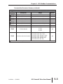
Communication Parameters Summary (continued)
Communications Parameter Summary (continued)
GS1
Parameter
쏆 P9.26
쏆 P9.27
쏆 P9.28
쏆 P9.29
쏆 P9.30
쏆 P9.31
P9.39
P9.41
P9.42
Description
Serial Comm Speed Reference
Range
Default
0.0 to 400.0 Hz
60.0
Serial Comm RUN Command
0: Stop
1: Run
0
Serial Comm Direction Command
0: Forward
1: Reverse
0
Serial Comm External Fault
0: No fault
1: External fault
0
Serial Comm Fault Reset
0: No action
1: Fault Reset
0
Serial Comm JOG Command
0: Stop
1: Jog
0
Firmware Version
GS Series Number
#.##
#.##
1: GS1
2: GS2
3: GS3
4: GS4
##
0: GS1-10P2 (120V, 1ph, 0.25hp)
1: GS1-10P5 (120V, 1ph, 0.5hp)
2: GS1-20P2 (230V, 1ph/3ph, 0.25hp)
Manufacturer Model Information
3: GS1-20P5 (230V, 1ph/3ph, 0.5hp)
4: GS1-21P0 (230V, 1ph/3ph, 1hp)
5: GS1-22P0 (230V, 3ph, 2hp)
##
쏆 Parameter can be set during RUN Mode.
2nd Edition
07/06/2011
GS1 Series AC Drive User Manual
5–3
Chapter 5: GS1 Modbus Communications
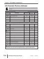
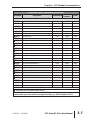
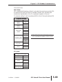
GS1 Parameter Memory Addresses
The octal address also can be used in the WX / RX instruction of the DL-250-1, DL-450,
and DL05.
Parameter Memory Addresses
GS1
Parameter
Description
Hexadecimal
Modbus
Decimal *
Octal
Motor Parameters
P0.00
P0.01
P0.02
P0.03
P0.04
Motor Nameplate Voltage
0000
40001
0
Motor Nameplate Amps
0001
40002
1
Motor Base Frequency
0002
40003
2
Motor Base RPM
0003
40004
3
Motor Maximum RPM
0004
40005
4
0100
40257
400
0101
40258
401
0102
40259
402
0103
40260
403
0104
40261
404
0105
40262
405
0106
40263
406
0107
40264
407
0108
40265
410
0109
40266
411
010A
40267
412
010B
40268
413
010C
40269
414
0111
40274
421
0113
40276
423
0114
40277
424
0115
40278
425
0116
40279
426
Ramp Parameters
Stop Methods
P1.00
Acceleration Time 1
쏆 P1.01
Deceleration Time 1
쏆 P1.02
Accel S-curve
P1.03
Decel S-curve
P1.04
Acceleration Time 2
쏆 P1.05
Deceleration Time 2
쏆 P1.06
Select method to use – 2nd Accel/Decel
P1.07
Accel 1 to Accel 2 frequency transition
P1.08
Decel 2 to Decel 1 frequency transition
P1.09
Skip Frequency 1
P1.10
Skip Frequency 2
P1.11
Skip Frequency 3
P1.12
Skip Frequency Band
P1.17
DC Injection Voltage Level
P1.19
DC Injection during Start-up
P1.20
DC Injection during Stopping
P1.21
Start-point for DC Injection
P1.22
쏆 Parameter can be set during RUN Mode.
* For Modbus Decimal addresses used with CLICK PLCs,
insert another zero as the next-to-most-significant digit, e.g., 402333 instead of 42333.
5–4
GS1 Series AC Drive User Manual
2nd Edition
07/06/2011
Chapter 5: GS1 Modbus Communications
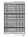
Parameter Memory Addresses (continued)
GS1
Parameter
Description
Modbus
Decimal *
Octal
0200
40513
1000
0201
40514
1001
0203
40516
1003
0204
40517
1004
0205
40518
1005
0206
40519
1006
0207
40520
1007
0208
40521
1010
0300
40769
1400
0301
40770
1401
0302
40771
1402
0303
40772
1403
030B
40780
1413
0310
40785
1420
0311
40786
1421
0400
41025
2000
0401
41026
2001
0402
41027
2002
0403
41028
2003
0404
41029
2004
0405
41030
2005
0500
41281
2400
0501
41282
2401
0502
41283
2402
0503
41284
2403
Hexadecimal
Volts/Hertz Parameters
Volts/Hertz Settings
P2.00
Slip Compensation
쏆 P2.01
Manual Torque Boost
쏆 P2.03
Mid-point Frequency
P2.04
Mid-point Voltage
P2.05
Minimum Output Frequency
P2.06
Minimum Output Voltage
P2.07
PWM Carrier Frequency
P2.08
쏆 Parameter can be set during RUN Mode.
Digital Parameters
Source of Operation Command
P3.00
Multi-function Input Terminals 1 & 2 (DI1 – DI2)
P3.01
Multi-function Input Terminal 3 (DI3)
P3.02
Multi-function Input Terminal 4 (DI4)
P3.03
Multi-Function Output Terminal 1 (Relay Output)
P3.11
Desired Frequency
쏆 P3.16
Desired Current
쏆 P3.17
쏆 Parameter can be set during RUN Mode.
Analog Parameters
Source of Frequency Command
P4.00
Analog Input Offset Polarity
쏆 P4.01
Analog Input Offset
쏆 P4.02
Analog Input Gain
쏆 P4.03
Analog Input Reverse Motion Enable
P4.04
Loss of ACI Signal (4-20 mA)
P4.05
쏆 Parameter can be set during RUN Mode.
Presets Parameters
Jog
쏆 P5.00
Multi-Speed 1
쏆 P5.01
Multi-Speed 2
쏆 P5.02
Multi-Speed 3
쏆 P5.03
쏆 Parameter can be set during RUN Mode.
* For Modbus Decimal addresses used with CLICK PLCs,
insert another zero as the next-to-most-significant digit, e.g., 402333 instead of 42333.
2nd Edition
07/06/2011
GS1 Series AC Drive User Manual
5–5
Chapter 5: GS1 Modbus Communications
Parameter Memory Addresses (continued)
Parameter
Description
Hexadecimal
Modbus
Decimal *
Octal
Protection Parameters
Electronic Thermal Overload Relay
0600
41537
P6.00
Auto Restart after Fault
0601
41538
P6.01
Momentary Power Loss
0602
41539
P6.02
Reverse Operation Inhibit
0603
41540
P6.03
Auto Voltage Regulation
0604
41541
P6.04
Over-Voltage Trip Protection
0605
41542
P6.05
Auto Adjustable Accel/Decel
0606
41543
P6.06
Over-Torque Detection Mode
0607
41544
P6.07
Over-Torque Detection Level
0608
41545
P6.08
Over-Torque Detection Time
0609
41546
P6.09
Over-Current Stall Prevention during Acceleration
060A
41547
P6.10
Over-Current Stall Prevention during Operation
060B
41548
P6.11
Maximum Allowable Power Loss Time
060C
41549
P6.12
Base-Block Time for Speed Search
060D
41550
P6.13
Maximum Speed Search Current Level
060E
41551
P6.14
Upper Bound of Output Frequency
060F
41552
P6.15
Lower Bound of Output Frequency
0610
41553
P6.16
Over-Voltage Stall Prevention Level
0611
41554
P6.17
Braking Voltage Level
0612
41555
P6.18
061E
41567
P6.30 † Line Start Lockout
Present Fault Record
061F
41568
P6.31
Second Most Recent Fault Record
0620
41569
P6.32
Third Most Recent Fault Record
0621
41570
P6.33
Fourth Most Recent Fault Record
0622
41571
P6.34
Fifth Most Recent Fault Record
0623
41572
P6.35
Sixth Most Recent Fault Record
0624
41573
P6.36
† - This parameter available only with firmware v1.07 or higher (refer to P9.39)
3000
3001
3002
3003
3004
3005
3006
3007
3010
3011
3012
3013
3014
3015
3016
3017
3020
3021
3022
3036
3037
3040
3041
3042
3043
3044
Display Parameters
User Defined Display Function
쏆 P8.00
Frequency Scale Factor
쏆 P8.01
쏆 Parameter can be set during RUN Mode.
0800
42049
4000
0801
42050
4001
* For Modbus Decimal addresses used with CLICK PLCs,
insert another zero as the next-to-most-significant digit, e.g., 402333 instead of 42333.
5–6
GS1 Series AC Drive User Manual
2nd Edition
07/06/2011
Chapter 5: GS1 Modbus Communications
Parameter Memory Addresses (continued)
Parameter
Description
Hexadecimal
Modbus
Decimal *
Octal
42305
4400
42306
4401
42307
4402
42308
4403
42309
4404
42310
4405
42312
4407
42313
4410
42316
4413
42317
4414
42318
4415
42319
4416
42320
4417
42321
4420
42322
4421
42323
4422
42324
4423
42325
4424
42331
4432
42332
4433
42333
4434
42334
4435
42335
4436
42336
4437
42344
4447
42346
4451
42347
4452
Communications Parameters
Communication Address
0900
P9.00
Transmission Speed
0901
P9.01
Communication Protocol
0902
P9.02
Transmission Fault Treatment
0903
P9.03
Time Out Detection
0904
P9.04
Time Out Duration
0905
P9.05
Parameter Lock
0907
쏆 P9.07
Restore to Default
0908
P9.08
Block Transfer Parameter 1
090B
쏆 P9.11
Block Transfer Parameter 2
090C
쏆 P9.12
Block Transfer Parameter 3
090D
쏆 P9.13
Block Transfer Parameter 4
090E
쏆 P9.14
Block Transfer Parameter 5
090F
쏆 P9.15
Block Transfer Parameter 6
0910
쏆 P9.16
Block Transfer Parameter 7
0911
쏆 P9.17
Block Transfer Parameter 8
0912
쏆 P9.18
Block Transfer Parameter 9
0913
쏆 P9.19
Block Transfer Parameter 10
0914
쏆 P9.20
Serial Comm Speed Reference
091A
쏆 P9.26
Serial Comm RUN Command
091B
쏆 P9.27
Serial Comm Direction Command
091C
쏆 P9.28
Serial Comm External Fault
091D
쏆 P9.29
Serial Comm Fault Reset
091E
쏆 P9.30
Serial Comm JOG Command
091F
쏆 P9.31
0927
P9.39 † Firmware Version
GS Series Number
0929
P9.41
Manufacturer Model Information
092A
P9.42
† - This parameter is available only with firmware v1.07 or higher.
쏆 Parameter can be set during RUN Mode.
* For Modbus Decimal addresses used with CLICK PLCs,
insert another zero as the next-to-most-significant digit, e.g., 402333 instead of 42333.
2nd Edition
07/06/2011
GS1 Series AC Drive User Manual
5–7
Chapter 5: GS1 Modbus Communications
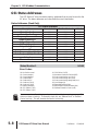
GS1 Status Addresses
The GS1 Series AC drive has status memory addresses that are used to monitor the
AC drive. The status addresses and value definitions are listed below.
Status Addresses (Read Only)
GS1 Status Addresses
Description
Status Monitor 1
Status Monitor 2
Frequency Command F
Output Frequency H
Output Current A
DC Bus Voltage d
Output Voltage U
Motor RPM
Scale Frequency (Low Word)
Scale Frequency (High Word)
% Load
Firmware Version
Hexadecimal
Modbus Decimal
Octal
2100
48449
20400
2101
48450
20401
2102
48451
20402
2103
48452
20403
2104
48453
20404
2105
48454
20405
2106
48455
20406
2107
48456
20407
2108
48457
20410
2109
48458
20411
210B
48460
20413
2110
48465
20420
Status Monitor 1
h2100
Error Codes:
00: No fault occurred
01: Over-current(oc)
02: Over-voltage(ov)
03: Overheat (oH)
04: Overload (oL)
05: Overload 1 (oL1)
06: Overload 2 (oL2)
07: External Fault (EF)
08: CPU Failure 1 (cF1)
09: CPU Failure 2 (cF2)
10: CPU Failure 3 (cF3)
11: Hardware Protection Failure (HPF)
12: Over-current during accel (ocA)
13: Over-current during decel (ocd)
14: Over-current during steady state (ocn)
16: Low Voltage (Lv)
18: External Base-Block (bb)
19: Auto Adjust accel/decel Failure (cFA)
20: Software Protection Code (codE)
Some error codes will not display under status address if only a warning message. The
drive must have a hard trip. To manually check this, set “External Fault” to Terminal
Control, and trip. This will simulate the result of a hard trip.
5–8
GS1 Series AC Drive User Manual
2nd Edition
07/06/2011
Chapter 5: GS1 Modbus Communications
Status Monitor 2
GS1 Memory Data (binary)
0
0
0
0
1
0
0
0
1
0
48
10
20
1
0
2
0
4
0
8
0
16
0
32
0
64
1
8
2
6
3
12
4
2
5
25
6
51
7
24
8
96
9
92
10
4
8
11
38
76
12
16
32
13
40
0
14
81
GS1 Memory Address
(hexadecimal) 15
2101
h2101
Bits
Bit Values
(decimal)
Status Monitor 2 - Memory Address h2101
Address
Bit(s) Value
AC Drive Status
Bit(s) Binary (Decimal)
0 and 1
2
00 (0)
Drive operation stopped (STOP)
01 (1)
Run to Stop transition
10 (2)
Standby
11 (3)
Drive operation running (RUN)
1 (4)
JOG active
00 (0)
Rotational direction forward (FWD)
01 (8)
REV to FWD transition
10 (16)
FWD to REV transition
11 (24)
Rotational direction reverse (REV)
1 (32)
Source of frequency determined by serial comm interface (P4.00 = 5)
6
1 (64)
Source of frequency determined by AI terminal (P4.00 = 2, 3, or 4)
7
1 (128)
Source of operation determined by serial comm interface (P3.00 = 3 or 4)
8
1 (256)
Parameters have been locked (P9.07 = 1)
9 ~ 15
N/A
3 and 4
5
Reserved
Frequency Command F (xxx.x)
h2102
Status location for the frequency setting of the AC drive.
Output Frequency H (xxx.x)
h2103
Status location for the actual operating frequency present at terminals T1, T2, and
T3.
Output Current A (xxx.x)
h2104
Status location for the output current present at terminals T1, T2, and T3.
2nd Edition
07/06/2011
GS1 Series AC Drive User Manual
5–9
Chapter 5: GS1 Modbus Communications
DC-BUS Voltage d (xxx.x)
h2105
Status location for the DC Bus Voltage.
Output Voltage U (xxx.x)
h2106
Status location for the output voltage present at terminals T1, T2, and T3.
(This is the RMS voltage between phases.)
Motor RPM
h2107
Status location for the present estimated speed of the motor.
Scale Frequency (Low word)
h2108
Status location for result of output frequency x P8.01 (low word).
Scale Frequency (High word)
h2109
Status location for result of output frequency x P8.01 (high word).
% Load
h210B
Status location for the amount of load on the AC drive. (Output Current ÷ Drive
Rated Current) x 100.
Firmware Version
h2110
Status location for firmware version of the AC drive.
5–10
GS1 Series AC Drive User Manual
2nd Edition
07/06/2011
Chapter 5: GS1 Modbus Communications
Communicating with AutomationDirect PLCs
The following steps explain how to connect and communicate with GS1 AC drives
using AutomationDirect PLCs.
GS1 drives have a provision for shutting down control or power to the inverter in the
event of a communications time out. This feature can be set up through parameters
P9.03, P9.04, and P9.05.
Step 1: Choose the Appropriate CPU
The GS1 AC drives will communicate with the following AutomationDirect PLCs
using Modbus communications.
• Modbus control is easier to accomplish from a DirectLOGIC PLC with an RS485 port and MRX/MWX, or from a CLICK PLC using Send/Receive instructions.
Choose Your CPU
CLICK Analog CPU with Send/Receive instructions & RS-485 comm port
D2-260 or DL06 with MRX / MWX instructions & RS-485 comm port
CLICK Basic CPU with Send/Receive instructions & RS-232 comm port
Secondary Choices DL05, D2-250(-1), or D4-450 with RX / WX instructions & RS-232 comm port
Primary Choices
Step 2: Make the Connections
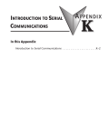
GS1 RS-485 Serial Comm Port
GS1 Serial Comm Port
RS-485 Interface
RJ12 (6P4C)
6
1
1:
2:
3:
4:
5:
6:
+17V
GND
SGSG+
nc
reserved
The GS1 Comm Port requires an RS-485 input. RS-232 signals can be converted
to RS-485 by using a separate converter.
PLC Connections for RS-485 Modbus RTU Control of GS1 Drive
Drive
GS1
PLC *
PLC Port *
Communication
Direct Cable
Length
CLICK
3
RS-485
ZL-RJ12-CBL-2P ***
2m [6.6 ft] ***
DL05
2 **
RS-232 – RS-485 **
DL06
D0-DCM
2
RS-485
D2-DCM
D2-250(-1)
2 **
RS-232 – RS-485 **
D2-260
2
RS-485
D4-450
3 **
RS-232 – RS-485 **
N/A **
GS-485HD15-CBL-2 ***
2m [6.6 ft] ***
N/A **
GS-485HD15-CBL-2 ***
2m [6.6 ft] ***
N/A **
* If a PLC type or port is not listed in this chart, it cannot function as a Modbus RTU master.
** Requires RS-232–RS-485 converter & generic cabling options described later in this chapter.
*** Termination resistors not required due to short cable length.
2nd Edition
07/06/2011
GS1 Series AC Drive User Manual
5–11
Chapter 5: GS1 Modbus Communications
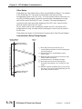
RS-485 Connections For Multiple Drives
ZIPLink™ RS-485 communication boards (ZL-CDM-RJ12X4 or ZL-CDM-RJ12X10)
provide an easy means to break out the RS-485 signal to several drives at one
location, which creates a star configuration. However, the transmission errors are
negligible, so this configuration is acceptable for proper operation of the VFDs.
RS-485 Direct Connections
Termination Resistors are required on both ends of RS-485 networks; especially on long
runs.
Select resistors that match the impedance rating of the cable (between 100 and 500Ω).
Recommended RS-485 cable: Belden 9842 or equivalent.
CLICK C0-02: RS-485 Connection Wiring
120⏲ Termination Resistor
at both ends of network
1
+
2
–
3
LG
TXD+ / RXD+
4 SG +
TXD– / RXD–
Signal GND
3 SG 2 GND
GS1
Comm Port
Node 1
CLICK C0-02
CPU Port 3
Connect shield
to signal ground
at one end only
4 SG +
GS1
Comm Port
3 SG 2 GND
Node 2
D0-DCM/DL06/DL260: RS-485 Connection Wiring
120⏲ Termination Resistor
at both ends of network
TXD+ / RXD+
4 SG +
TXD– / RXD–
3 SG 2 GND
Signal GND
RXD–
1
6
GS1
Comm Port
Node 1
11
4 SG +
GS1
Comm Port
RTS+
0V
TXD+ RXD+
3 SG 2 GND
RTS–
CTS+
Node 2
10
5
15
CTS–
TXD–
Connect shield
to signal ground
at one end only
D0-DCM/DL06/DL260 Port 2
5–12
GS1 Series AC Drive User Manual
2nd Edition
07/06/2011
Chapter 5: GS1 Modbus Communications
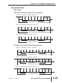
RS-232C to RS-485 Conversion
An RS-485 network cable can span up to 1000 meters (4000 feet). However, most
DirectLOGIC PLCs have only RS-232C communication ports, and require an
FA-ISOCON (RS-232C to RS-422/485 network adapter) in order to make an RS-485
connection.
If an FA-ISOCON module is used, set the module dipswitches as required.
Refer to the FA-ISOCON manual for more detailed information.
FA-ISOCON Switch Settings:
S21~S23
S24~S27
Terminate
Bias (2)
1/2 DPX (2)
OFF, ON, ON (19200 baud)
OFF (Automatic Network Transmit Enable)
ON (end of run term resistors)
ON (end of run bias resistors)
ON (RS-485 TXD/RXD jumpers)
FA-ISOCON RJ-12 Serial Comm Port A
RS-232 Input Port
6
1
1:
2:
3:
4:
5:
6:
Signal Ground
CTS (input)
RXD (input)
TXD (output)
+5VDC in
Signal Ground
Use the following wiring diagrams to connect DirectLOGIC RS-232C PLCs to a
GS1 Series AC drive with an FA-ISOCON network adapter module:
Recommended cable for RS-232: Belden 8102 or equivalent.
Recommended cable for RS-485: Belden 9842 or equivalent.
2nd Edition
07/06/2011
GS1 Series AC Drive User Manual
5–13
Chapter 5: GS1 Modbus Communications
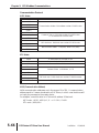
RS-232C to RS-485 Conversion (continued)
DL05: RS-232C to RS-485 Connection Wiring
120⏲ Termination Resistor
at both ends of network
C
DL05
PORT 2
1
2
3
4
5
6
0V
5V
RXD
TXD
RTS
0V
6
5
4
3
2
1
COM A
+5VDC
TXD
RXD
CTS
COM A
+V
COM A
A
D
No connection
(for DL05)
TXD+
TXD-
4 SG +
3 SG -
RXDRXD+
GS1
Comm Port
2 GND
COM B
Node 1
FA-ISOCON
RS-232 to RS-485 converter with ANTE
Connect shield
to signal ground
at one end only
4 SG +
GS1
Comm Port
3 SG 2 GND
Connect shield
to signal ground
at one end only
Node 2
120⏲ Termination Resistor at both ends of network
A cable (ZL-RJ12-CBL-2) is available that will connect the DL05 to the FA-ISOCON.
A cable can also be constructed using the FA-15HD adapter and RJ12-6P6C cable from
the FA-CABKIT.
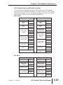
D0-DCM/DL250(-1): RS-232C to RS-485 Connection Wiring
120⏲ Termination Resistor
at both ends of network
D0-DCM/DL250
PORT 2
1
6
2
3
5
4
7
TXD
RXD
CTS
RTS
GND
C
3 RXD
4 TXD
+V
COM A
A
D
TXD+
TXD-
2 CTS
6 GND
RXDRXD+
15
24VDC +
24VDC -
COM B
4 SG +
3 SG -
GS1
Comm Port
2 GND
Node 1
FA-ISOCON
RS-232 to RS-485 converter with ANTE
Connect shield
to signal ground
at one end only
4 SG +
Connect shield
to signal ground
at one end only
GS1
Comm Port
3 SG 2 GND
Node 2
120⏲ Termination Resistor at both ends of network
A cable that will connect the D0-DCM or DL250 to the FA-ISOCON can be
constructed using the FA-15HD adapter and the D0-CBL cable. A cable can also be
constructed using the FA-15HD adapter and RJ12-6P6C cable from the FA-CABKIT.
5–14
GS1 Series AC Drive User Manual
2nd Edition
07/06/2011
Chapter 5: GS1 Modbus Communications
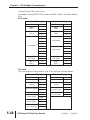
RS-232C to RS-485 Conversion (continued)
DL350/DL450: RS-232C to RS-485 Connection Wiring
120⏲ Termination Resistor
at both ends of network
DL350 PORT 2
DL450 PORT 1
C
1
2
3
5
4
7
TXD
RXD
CTS
RTS
GND
3 RXD
4 TXD
+V
COM A
A
D
TXD+
TXD-
2 CTS
6 GND
24VDC +
24VDC -
RXDRXD+
COM B
4 SG +
3 SG -
GS1
Comm Port
2 GND
25
Node 1
FA-ISOCON
RS-232 to RS-485 converter with ANTE
4 SG +
Connect shield
to signal ground
at one end only
GS1
Comm Port
3 SG 2 GND
Node 2
120⏲ Termination Resistor at both ends of network
A cable that will connect the DL450 to the FA-ISOCON can be constructed using the
DB25-pin-male-to-RJ12 adapter and the RJ12-6P6C cable from the FA-CABKIT.
Ethernet Connection using GS-EDRV
The GS-EDRV provides an Ethernet link between a control system and a GS1 AC
drive. It mounts on DIN rail and connects a drive to an Ethernet hub/switch or
PC. The GS-EDRV processes signals to and from the drive. It formats the signals
to conform with the Ethernet standard to the H2-ERM or H4-ERM, KEPdirect EBC
I/O server, or independent controller with a MODBUS TCP/IP driver. This Ethernet
interface allows for great connectivity to many control system architectures. An
additional feature is the built-in web browser which allows users to configure and
control the drive from any web browser via the IP address of the GS-EDRV card.
2nd Edition
07/06/2011
GS1 Series AC Drive User Manual
5–15
Chapter 5: GS1 Modbus Communications
Step 3: Set AC Drive Parameters
The following parameters need to be set as shown in order to communicate
properly.
P3.00:
03 or 04
Operation Determined by RS-485 interface.
Keypad STOP is enabled (03) or disabled (04).
P4.00:
05
Frequency determined by RS-485 communication
interface.
P9.00:
xx
Communication address 1-254
(unique for each device, see P9.00).
P9.01:
01
9600 baud data transmission speed
(higher baud rate setting may be required with
FA-ISOCON network adapter; set adapter DIP switches
accordingly).
P9.02:
05
MODBUS RTU mode
<8 data bits, odd parity, 1 stop bit>.
This list of parameter settings is the minimum required to communicate with a
DirectLOGIC PLC. There may be other parameters that need to be set to meet the
needs of your particular application.
Step 4: Configure the PLC CPU
The PLC CPUs must be configured to communicate with the GS1 AC drives. This
configuration includes setting up the communication port and adding instructions
to your logic program.
The set up for all of the AutomationDirect PLC CPUs is very similar, although
there are some subtle differences between CPUs. Refer to the appropriate CPU
User Manual for the specifics on your specific PLC CPU if more details are
needed.
For instructions on Modbus Configuration for your specific PLC CPU, refer to the
appropriate PLC User Manual.
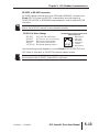
Configure the CLICK PLC
Configure the CLICK CPU communication port before writing communication
instructions into your logic program.
For more detailed instructions on Modbus Configuration for your CLICK, refer to the
CLICK PLC Hardware User Manual, C0-USER-M, or to the CLICK software help file.
5–16
GS1 Series AC Drive User Manual
2nd Edition
07/06/2011
Chapter 5: GS1 Modbus Communications
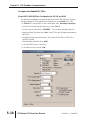
CLICK Port 3 MODBUS Configuration for RS-485
The following configuration example is specific for CLICK PLC CPUs.
• Configure the communication port before writing communication instructions into
the logic program.
• In CLICK programming software, open the “Comm Port Details Setup” dialog box
by choosing the Setup menu, then Comm Port Setup, then Port 2 Setup.
• From the “Port:” list box, choose “Port 3”.
• For the “Protocol:” list box, select “Modbus”.
• Set the “Node Address” to “1” to make the CLICK PLC a MODBUS master.
• Set the “Baud Rate” to “19200”
• Set the “Parity” to “Odd”.
• Set the “Stop Bit” to “1”.
• Set the “Time-out Setting” to “500ms”.
• Set the “Response Delay Time” to “0ms”.
The communication port settings are saved in the project file. The project must be
transferred to the CLICK PLC in order for any port setting changes to take effect.
2nd Edition
07/06/2011
GS1 Series AC Drive User Manual
5–17
Chapter 5: GS1 Modbus Communications
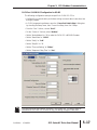
Configure the DirectLOGIC CPUs
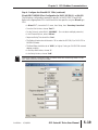
DirectLOGIC MODBUS Port Configuration for D2-260 and DL06
The following configuration example is specific to the D2-260 and DL06. Refer to
the appropriate CPU User Manual for the specifics on your DirectLOGIC CPU.
• In DirectSOFT, choose the PLC menu, then Setup, then ”Secondary Comm Port”.
• From the Port number list box at the top, choose “Port 2”.
• For the Protocol, select ONLY “MODBUS”. (Do not select multiple protocols.)
• Response Delay Time should be “0ms”. Both RTS on and off delay times must be
set to 0ms .
• The Station Number should be set to “1” to make the D2-260 or DL06 CPU a
MODBUS master.
• The Baud Rate should be set at “9600”.
• In the Stop Bits list box, Choose “1”.
• In the Parity list box, choose “Odd”.
5–18
GS1 Series AC Drive User Manual
2nd Edition
07/06/2011
Chapter 5: GS1 Modbus Communications
Step 4: Configure the DirectLOGIC CPUs (continued)
DirectLOGIC MODBUS Port Configuration for DL05, D2-250(-1), or D4-450
The following configuration example is specific to the D2-250(-1) and DL05.
Refer to the appropriate CPU User Manual for the specifics on your DirectLogic
CPU.
• In DirectSOFT, choose the PLC menu, then Setup, then “Secondary Comm Port”.
• From the Port list box, choose “Port 2”.
• For the Protocol, select ONLY “MODBUS”. (Do not select multiple protocols.)
• In the Timeout list box, select “800 ms”.
• Response Delay Time should be “0ms”.
• The Station Number should be set to “1” to make the D2-250(-1) or DL05 CPU a
MODBUS Master.
• The Baud Rate should be set at “9600” (or higher, if using an FA-ISOCON network
adapter module).
• In the Stop Bits list box, choose “1”.
• In the Parity list box, choose “Odd”.
The DL250 network instructions used in Master mode will access only slaves 1 to 90.
Each slave must have a unique number.
2nd Edition
07/06/2011
GS1 Series AC Drive User Manual
5–19
Chapter 5: GS1 Modbus Communications
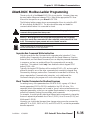
CLICK Modbus Ladder Programming
The set up for all of the CLICK CPUs is very similar. However, there may be some
subtle differences between CPUs, or for the requirements of your particular
program. Refer to the CLICK programming software internal help file for more
information regarding CLICK programming.
The following ladder program shows some examples of how to control the GS1
AC drive through Modbus RTU. The drive should be set up and tested for
communications before it is connected to a load.
WARNING: A drive should never be connected to a load until any applicable
communication programs have been proven.
WARNING: Write programs in such a way that the program does not erroneously
overwrite a remote Stop command with a Run command, such as when P3.00 is set
to 03. This example program prevents such an accidental overwrite.
These programs are for illustrational purposes only,
and are not intended for a true application.
Separate Run Command Write Instruction
Why do we write the Run Command with a separate write instruction? If we
write the Run Command to the drive along with the Speed Reference, Direction,
External Fault, and Fault Reset Commands, we can keep the parameter addresses
in sequence, and we can update all five of the commands with one write
instruction. This method is valid only if we disable the drive’s keypad STOP
button (P3.00 = 04).
Typically, the keypad STOP button will be enabled (P3.00 = 03), and we need to
prevent a change in one of the other commands from overriding a keypad Stop
Command by causing a previous Run Command to be rewritten to the drive. By
using a separate Run Command write instruction, only a deliberate Run
Command change by the program will run the drive again after a stop.
Block Transfer Parameters for Modbus Programs
For writing to any of the parameters from P0.00 to P8.01, a group of 10 block
transfer parameters (P9.11 to P9.20) is available in the GS1 AC drive. This
sequential block of parameters can be used to "group" various miscellaneous nonsequential parameters, so that you can update the parameters in one programming
write block instead of having to use multiple write commands.
For example, it would typically take three different write commands to change the
three non-sequential parameters Accel Time 1 (P1.01), Accel S-curve (P1.03), and
Multi-speed 1 (P5.01).
However, you could make the same three changes using one write command by
setting P9.11 to P1.01, P9.12 to P1.03, and P9.13 to P5.01, so that the parameters
become sequential.
5–20
GS1 Series AC Drive User Manual
2nd Edition
07/06/2011
Chapter 5: GS1 Modbus Communications
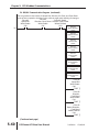
CLICK Communication Program – (for CLICK PLCs)
This program is for illustrational purposes only, and is not intended for a true application.
This rung counts the number of times the PLC attempts to communicate with the drives.
1
CT1
Counter
_Port_3_Ready_Flag
bSC102
bCT1
Up
bCT1
SetPoint
i9999
Current
ICTD1
Complete
Reset
This rung counts the number of comm attempts that failed.
CT2
Counter
_Port_3_Error_Flag
bSC103
bCT2
2
Up
bCT2
SetPoint
i9999
Current
ICTD2
Complete
Reset
Read Drive #1 Error
bC202
Read Drive #2 Error
bC205
This rung acts as an alternator, allowing the following logic to alternate between Drive #1 and
Drive #2. If there were additional drives, the Setpoint for the counter would simply be increased to
match the number of drives.
(Coordinates the
Counter
CT3 Receive boxes, so they
_Port_3_Ready_Flag
toggle back and forth.)
bSC102
3
Up
(Coordinates the Receive boxes,
so they toggle back and forth.)
Comm Interlock Counter
bCT3
SetPoint
i2
Current
ICTD3
Comm Interlock
Counter
bCT3
Complete
Reset
(Continued next page)
2nd Edition
07/06/2011
GS1 Series AC Drive User Manual
5–21
Chapter 5: GS1 Modbus Communications
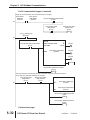
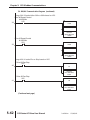
CLICK Communication Program (continued)
This rung checks to see if it is time to communicate to Drive #1, and also if there are no current
Write requests to that drive. If not, it reads data from Drive #1.
_Port_3_Ready_Flag
bSC102
ICTD3
i0
Drive #1 Speed Ref Write-Enable
bC10
4
Drive #1 Direction,
Fault, Reset,
Write-Enable
bC11
Drive #1 CMD
Write-Enable
bC12
MODBUS
Receive (Port3)
1
Slave ID
bC200
03
Modbus Function Code
408449 Receiving
Slave Addr
12
NO. of Master Addresses
OFF
Word Swap
Read Drive #1
Success
Status from Drive #1
bC201
iDS1
Master
Success
Read Drive #1
Error
bC202
Error
ErrC...
iDS100
This rung checks to see if it is time to communicate to Drive #2, and also if there are no current
Write requests to that drive. If not, it reads data from Drive #2.
_Port_3_Ready_Flag
bSC102
ICTD3
i1
Drive #2 Speed Ref Write Enable
bC30
5
Drive #2 Direction,
Fault, Reset,
Drive #2 Run CMD
Write-Enable
Write-Enable
bC31
bC32
MODBUS
Receive (Port3)
2
Slave ID
bC203
03
Modbus Function Code
408449 Receiving
Slave Addr
12
NO. of Master Addresses
OFF Read Drive #2
Word Swap
Success
Status from Drive #2
bC204
iDS20
Master
Success
Read Drive #2
Error
bC205
Error
ErrC...
iDS103
(Continued next page)
5–22
GS1 Series AC Drive User Manual
2nd Edition
07/06/2011
Chapter 5: GS1 Modbus Communications
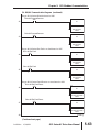
CLICK Communication Program (continued)
6
This rung resets all the Receive status coils if either comm event is successful.
Read Drive #1 Success
bC201
bC200
bC206
RST
Read Drive #2 Success
bC204
** The following rungs are used for Drive #1 communications, through rung #27 **
Status from Drive #1
iDS1
i1
7
Drive #1 Fault Indication
bC100
8
Status from Drive #1
iDS1
i4
9
Drive #1 Overload Indicator
bC101
10
Drive #1 Fault
bC1
SET
Drive #1 Fault
bC1
RST
Drive #1 Overload
bC2
SET
Drive #1 Overload
bC2
SET
This rung determines if the Speed, Direction, Ext Fault, or Fault Reset
words have changed and need to be written.
Drive #1 Speed
Drive #1 Speed
Drive #1 Speed Ref Write Enable
Ref New
Ref Retain
bC10
iDS300
iDS310
11
Drive #1
Direction New
iDS302
Drive #1
Direction Retain
iDS312
Drive #1 Ext
Fault New
iDS303
Drive #1 Ext
Fault Retain
iDS313
Drive #1 Fault
Reset New
iDS304
Drive #1 Fault
Reset Retain
iDS314
Drive #1 Run CMD
Write Enable
bC12
Drive #1 Speed
Ref Write Enable
bC10
SET
(Continued next page)
2nd Edition
07/06/2011
GS1 Series AC Drive User Manual
5–23
Chapter 5: GS1 Modbus Communications
CLICK Communication Program (continued)
This rung writes the new Speed Reference if it changes.
_Port_3_Ready_Flag
bSC102
Drive #1 Speed Ref Write Enable
bC10
12
Drive #1 Direction,
Fault, Reset
Write-Enable
bC11
Send(Port3)
Slave ID
Modbus Function Code
Slave Addr
Master
MODBUS
1
bC206
06
402331 Sending
Drive #1 Speed Ref New
iDS300
bC207
Success
bC208
Error
iDS106
ErrC...
Drive #1 Direction, Fault, Reset Write-Enable
bC11
SET
This rung writes the Direction, Ext Fault, and Fault Reset words if any of them changes.
_Port_3_Ready_Flag
Drive #1 Speed Ref Write Enable
bSC102
bC10
13
Drive #1 Direction,
Fault, Reset
Write-Enable
bC11
MODBUS
Send(Port3)
1
Slave ID
bC209
16
Modbus Function Code
402333 Sending
Slave Addr
3
NO. of Master Addresses
Word Swap
OFF
Master
Drive #1 Direction New
iDS302
bC210
Success
bC211
Error
ErrC...
iDS109
Drive #1 Speed, Direction, Fault, Reset writes finished
bC13
SET
(Continued next page)
5–24
GS1 Series AC Drive User Manual
2nd Edition
07/06/2011
Chapter 5: GS1 Modbus Communications
CLICK Communication Program (continued)
This rung writes the new values for Speed Ref, Direction, Ext Fault, and Fault Reset
words to their comparison locations so the code can again start watching for changes.
Drive #1 Speed Ref Write Enable
Drive #1 Direction, Fault, Reset Write-Enable
bC10
bC11
14
Drive #1 Speed, Direction, Fault,
Reset, writes finished
bC13
Copy
Single
Src
Drive #1 Speed Ref New
iDS300
Des
Drive #1 Speed Ref Retain
iDS310
Copy
Single
Src
Drive #1 Direction New
iDS302
Des
Drive #1 Direction Retain
iDS312
Copy
Single
Src
Drive #1 Ext Fault New
iDS303
Des
Drive #1 Ext Fault Retain
iDS313
Copy
Single
Src
Drive #1 Fault Reset New
iDS304
Des
Drive #1 Fault Reset Retain
iDS314
Drive #1 Speed Ref Write Enable
bC10
RST
Drive #1 Direction, Fault, Reset Write Enable
bC11
RST
Drive #1 Speed Direction, Fault, Reset writes finished
bC13
RST
(Continued next page)
2nd Edition
07/06/2011
GS1 Series AC Drive User Manual
5–25
Chapter 5: GS1 Modbus Communications
CLICK Communication Program (continued)
Rungs 15 & 16 write to the Run Command word if it changes.
Drive #1 Run CMD New
iDS301
Drive #1 Run CMD Retain
iDS311
Drive #1 Speed Ref Write Enable
bC10
15
Drive #1 Run CMD Write-Enable
bC12
16
_Port_3_Ready_Flag
bSC102
Drive #1 Speed Ref Write-Enable
bC12
SET
Drive #1 Run CMD Write-Enable
bC12
Send(Port3)
Slave ID
Modbus Function Code
Slave Adder
Master
MODBUS
1
16
402332
bC212
Sending
Drive #1 Run CMD New
iDS301
bC213
Success
bC214
Error
ErrC...
iDS112
Drive #1 Run CMD Write finished
bC14
SET
(Continued next page)
5–26
GS1 Series AC Drive User Manual
2nd Edition
07/06/2011
Chapter 5: GS1 Modbus Communications
CLICK Communication Program (continued)
This rung writes the new value for the Run Command word to its comparison location
so the code can again start watching for changes.
Drive #1 Run CMD Write-Enable
bC12
Drive #1 Run CMD Write finished
bC14
17
Single
Copy
Src
Drive #1 Run CMD New
iDS301
Des
Drive #1 Run CMD Retain
iDS311
Drive #1 Run CMD Write-Enable
bC12
RST
Drive #1 Run CMD Write finished
bC14
RST
Rungs 18 & 19 select either 30Hz or 60Hz based on C102.
Drive #1 Speed Control 60/30 Hz
bC102
18
Drive #1 Speed Control 60/30 Hz
bC102
19
Single
Copy
Src
i300
Des
Drive #1 Speed Ref New
iDS300
Single
Copy
Src
i600
Des
Drive #1 Speed Ref New
iDS300
Rungs 20 & 21 select Run or Stop based on C103.
Drive #1 Run Stop
Copy
bC103
Src
20
Des
Drive #1 Run Stop
bC103
21
Single
i1
Drive #1 Run CMD New
iDS301
Single
Copy
Src
i0
Des
Drive #1 Run CMD New
iDS301
(Continued next page)
2nd Edition
07/06/2011
GS1 Series AC Drive User Manual
5–27
Chapter 5: GS1 Modbus Communications
CLICK Communication Program (continued)
Rungs 22 & 23 select Direction based on C104.
Drive #1 Fwd Rev
bC104
22
Drive #1 Fwd Rev
bC104
23
Single
Copy
Src
i1
Des
Drive #1 Direction New
iDS302
Single
Copy
Src
i0
Des
Drive #1 Direction New
iDS302
Rungs 24 & 25 select Ext Fault or no fault based on C105.
Drive #1 Fault
bC105
24
Drive #1 Fault
bC105
25
Single
Copy
Src
i1
Des
Drive #1 Ext Fault New
iDS303
Single
Copy
Src
i0
Des
Drive #1 Ext Fault New
iDS303
Rungs 26 & 27 select Fault Reset or no reset based on C106.
Drive #1 Ext Fault Reset
Copy
bC106
i1
Src
26
Des
Drive #1 Ext Fault Reset
bC106
27
Single
Drive #1 Fault Reset New
iDS304
Single
Copy
Src
i0
Des
Drive #1 Fault Reset New
iDS304
(Continued next page)
5–28
GS1 Series AC Drive User Manual
2nd Edition
07/06/2011
Chapter 5: GS1 Modbus Communications
CLICK Communication Program (continued)
** The remaining rungs are for Drive #2 communications. **
Status from Drive #2
iDS20
i1
28
Drive #2 Fault Indication
bC107
29
Status from Drive #2
iDS20
i4
30
Drive #2 Overload Indicator
bC108
31
Drive #2 Fault
bC20
SET
Drive #2 Fault
bC20
RST
Drive #2 Overload
bC21
SET
Drive #2 Overload
bC21
SET
This rung determines if the Speed, Direction, Ext Fault, or Fault Reset
words have changed and need to be written.
Drive #2 Speed Drive #2 Speed
Drive #2 Speed Ref
Ref Retain
Ref New
Write Enable
iDS330
iDS320
bC30
32
Drive #2
Direction New
iDS322
Drive #2
Direction Retain
iDS332
Drive #2 Ext
Fault New
iDS323
Drive #2 Ext
Fault Retain
iDS333
Drive #2 Fault
Reset New
iDS324
Drive #2 Fault
Reset Retain
iDS334
Drive #2 Run CMD
Write Enable
bC32
Drive #2 Speed Ref
Write Enable
bC30
SET
(Continued next page)
2nd Edition
07/06/2011
GS1 Series AC Drive User Manual
5–29
Chapter 5: GS1 Modbus Communications
CLICK Communication Program (continued)
This rung writes the new Speed Reference if it changes.
_Port_3_Ready_Flag
Drive #2 Speed Ref Write Enable
bSC102
bC30
33
Drive #2 Direction,
Fault, Reset,
Write Enable
bC31
Send(Port3)
Slave ID
Modbus Function Code
Slave Addr
Master
MODBUS
2
bC215
06
402331 Sending
Drive #2 Speed Ref New
iDS320
bC216
Success
bC217
Error
ErrC...
iDS115
Drive #2 Direction, Fault, Reset, Write Enable
bC31
SET
This rung writes the Direction, Ext Fault, and Fault Reset words if any of them changes.
_Port_3_Ready_Flag
Drive #2 Speed Ref Write Enable
bSC102
bC30
34
Drive #2 Direction,
Fault, Reset,
Write-Enable
bC31
MODBUS
Send(Port3)
2
Slave ID
bC218
16
Modbus Function Code
402333
Slave Addr
Sending
3
NO. of Master Addresses
OFF
Word Swap
Master
Drive #2 Direction New
iDS322
bC219
Success
bC220
Error
ErrC...
iDS118
Drive #2 Speed, Direction, Fault, Reset, writes finished
bC33
SET
(Continued next page)
5–30
GS1 Series AC Drive User Manual
2nd Edition
07/06/2011
Chapter 5: GS1 Modbus Communications
CLICK Communication Program (continued)
This rung writes the new values for Speed Ref, Direction, Ext Fault, and Fault Reset
words to their comparison locations so the code can again start watching for changes.
Drive #2 Direction, Fault, Reset, Write-Enable
Drive #2 Speed Ref Write Enable
bC31
bC30
35
Drive #2 Speed, Direction, Fault,
Reset, writes finished
bC33
Src
Single
Drive #2 Speed Ref New
iDS320
Des
Drive #2 Speed Ref Retain
iDS330
Copy
Copy
Src
Drive #2 Direction Retain
iDS332
Des
Copy
Src
Copy
Des
Single
Drive #2 Ext Fault New
iDS323
Drive #2 Ext Fault Retain
iDS333
Des
Src
Single
Drive #2 Direction New
iDS322
Single
Drive #2 Fault Reset New
iDS324
Drive #2 Fault Reset Retain
iDS334
Drive #2 Speed Ref Write Enable
bC30
RST
Drive #2 Direction, Fault, Reset Write-Enable
bC31
RST
Drive #2 Speed, Direction, Fault, Reset writes finished
bC33
RST
(Continued next page)
2nd Edition
07/06/2011
GS1 Series AC Drive User Manual
5–31
Chapter 5: GS1 Modbus Communications
CLICK Communication Program (continued)
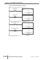
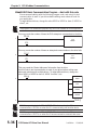
Rungs 36 & 37 write to the Run Command word if it changes.
Drive #2 Run
CMD New
iDS321
Drive #2 Run
CMD Retain
iDS331
Drive #2 Speed Ref Write Enable
bC30
36
Drive #2 Run CMD
Write-Enable
bC32
Drive #2 Run CMD
Write-Enable
bC32
SET
_Port_3_Ready_Flag
bSC102
37
Drive #2 Run CMD Write-Enable
bC32
Send(Port3)
Slave ID
Modbus Function Code
Slave Adder
Master
MODBUS
2
06
402332
bC221
Sending
Drive #2 Run CMD New
iDS321
bC222
Success
bC223
Error
ErrC...
iDS121
Drive #2 Run CMD Write finished
bC34
SET
This rung writes the new value for the Run Command word to its comparison location
so the code can again start watching for changes.
Drive #2 Run CMD
Drive #2 Run CMD
Copy
Single
Write-Enable
Write finished
bC32
bC34
Drive #2 Run CMD New
38
Src
iDS321
Des
Drive #2 Run CMD Retain
iDS331
Drive #2 Run CMD Write-Enable
bC32
RST
Drive #2 Run CMD write finished
bC34
RST
(Continued next page)
5–32
GS1 Series AC Drive User Manual
2nd Edition
07/06/2011
Chapter 5: GS1 Modbus Communications
CLICK Communication Program (continued)
Rungs 39 & 40 select either 30Hz or 60Hz based on C109.
Drive #2 Speed Control 60/30 Hz
bC109
39
Drive #2 Speed Control 60/30 Hz
bC109
40
Single
Copy
Src
i300
Des
Drive #2 Speed Ref New
iDS320
Single
Copy
Src
i600
Des
Drive #2 Speed Ref New
iDS320
Rungs 41 & 42 select Run or Stop based on C110.
Drive #2 Run Stop
Copy
bC110
Src
41
Des
Drive #2 Run Stop
bC110
42
Drive #2 Run CMD New
iDS321
Single
Src
i0
Des
Drive #2 Run CMD New
iDS321
Des
44
i1
Copy
Rungs 43 & 44 select Direction based on C111.
Drive #2 Fwd Rev
Copy
bC111
Src
43
Drive #2 Fwd Rev
bC111
Single
Single
i1
Drive #2 Direction New
iDS322
Single
Copy
Src
i0
Des
Drive #2 Direction New
iDS322
(Continued next page)
2nd Edition
07/06/2011
GS1 Series AC Drive User Manual
5–33
Chapter 5: GS1 Modbus Communications
CLICK Communication Program (continued)
Rungs 45 & 46 select Ext Fault or no fault based on C112.
Drive #2 Fault
Copy
bC112
Src
45
Des
Drive #2 Fault
bC112
46
Single
i1
Drive #2 Ext Fault New
iDS323
Single
Copy
Src
i0
Des
Drive #2 Ext Fault New
iDS323
Rungs 47 & 48 select Fault Reset or no reset based on C113.
Drive #2 Ext Fault Reset
Copy
bC113
Src
47
i1
Des
Drive #2 Ext Fault Reset
bC113
48
Drive #2 Fault Reset New
iDS324
Single
Copy
Src
i0
Des
Drive #2 Fault Reset New
iDS324
49
5–34
Single
GS1 Series AC Drive User Manual
END
2nd Edition
07/06/2011
Chapter 5: GS1 Modbus Communications
DirectLOGIC Modbus Ladder Programming
The set up for all of the DirectLOGIC CPUs is very similar. However, there may
be some subtle differences between CPUs. Refer to the appropriate CPU User
Manual for the specifics on your DirectLOGIC CPU.
The following ladder program shows some examples of how to control the GS1
AC drive through Modbus RTU. The drive should be setup and tested for
communications before it is connected to a load.
WARNING: A drive should never be connected to a load until any applicable
communication programs have been proven.
WARNING: Write programs in such a way that the program does not erroneously
overwrite a remote Stop command with a Run command, such as when P3.00 is set
to 03. This example program prevents such an accidental overwrite.
These programs are for illustrational purposes only,
and are not intended for a true application.
Separate Run Command Write Instruction
Why do we write the Run Command with a separate write instruction? If we
write the Run Command to the drive along with the Speed Reference, Direction,
External Fault, and Fault Reset Commands, we can keep the parameter addresses
in sequence, and we can update all five of the commands with one write
instruction. This method is valid only if we disable the drive’s keypad STOP
button (P3.00 = 04).
Typically, the keypad STOP button will be enabled (P3.00 = 03), and we need to
prevent a change in one of the other commands from overriding a keypad Stop
Command by causing a previous Run Command to be rewritten to the drive. By
using a separate Run Command write instruction, only a deliberate Run
Command change by the program will run the drive again after a stop.
Block Transfer Parameters for Modbus Programs
For writing to any of the parameters from P0.00 to P8.01, a group of 10 block
transfer parameters (P9.11 to P9.20) is available in the GS1 AC drive. This
sequential block of parameters can be used to "group" various miscellaneous nonsequential parameters, so that you can update the parameters in one programming
write block instead of having to use multiple write commands.
For example, it would typically take three different write commands to change the
three non-sequential parameters Accel Time 1 (P1.01), Accel S-curve (P1.03), and
Multi-speed 1 (P5.01).
However, you could make the same three changes using one write command by
setting P9.11 to P1.01, P9.12 to P1.03, and P9.13 to P5.01, so that the parameters
become sequential.
2nd Edition
07/06/2011
GS1 Series AC Drive User Manual
5–35
Chapter 5: GS1 Modbus Communications
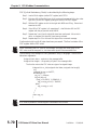
DirectLOGIC Basic Communication Program – start with this code
We recommend starting with the following program code, and using it to test
communication to each of your drives before adding more advanced code for
your application.
To target different drives, change the value Kf201 to Kf202 for slave 2, Kf203 for
slave 3, etc.
This program is for illustrational purposes only, and is not intended for a true application.
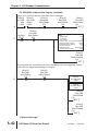
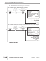
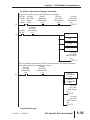
This rung counts the number of times the PLC attempts to communicate to the drive.
SP116
CNT
1
CT0
CT0
K9999
This rung counts the number of times an attempted communication to the drive fails.
CNT
SP117
2
CT1
K9999
CT1
This rung reads the ‘Status Addresses’ information from the drive.
Use this code to test communication to each of your drives before writing more
advanced code that polls multiple drives. To target different drives, change the
value ‘Kf201’ to ‘Kf202’ for slave 2, ‘Kf203’ for slave 3, etc.
SP116
LD
3
Kf201
LD
K24
LDA
O2000
RX
V20400
( END )
4
SP116 is a special relay in the DirectLOGIC CPUs that monitors the PLC’s
communications. SP116 is on when Port 2 is communicating with another device.
SP117 is a special relay in the DirectLOGIC CPUs that monitors the PLC’s
communications. SP117 is on when Port 2 has encountered a communication error.
5–36
GS1 Series AC Drive User Manual
2nd Edition
07/06/2011
Chapter 5: GS1 Modbus Communications
Programming Differences for DirectLOGIC PLCs
Different types of DirectLOGIC PLCs can be programmed differently, depending
upon the types of network read and write instructions they can perform. There are
two different types of these instructions, and this User Manual shows
programming examples of both types.
RX/WX Instructions for DL05, D2-250(-1), D4-450
PLCs with DL05, D2-250, D2-250-1, and D4-450 CPUs can read from and write
to networks using RX (Read from Network) and WX (Write to Network)
programming instructions.
MRX/MWX Instructions for DL06, D2-260
In addition to the RX and WX instructions listed above, PLCs with DL06 and D2260 CPUs can also read from and write to networks using MRX (Modbus Read
from Network) and MWX (Modbus Write to Network) programming instructions.
The MRX and MWX instructions are simpler and easier to use than are the RX and
WX instructions. Therefore, we recommend that you use DL06 or D2-260 with
MRX and MWX instructions if you have a choice.
2nd Edition
07/06/2011
GS1 Series AC Drive User Manual
5–37
Chapter 5: GS1 Modbus Communications
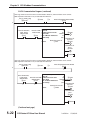
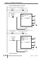
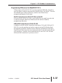
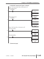
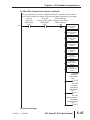
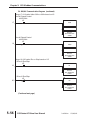
DL MRX/MWX Communication Program – for DL06 & D2-260 PLCs
This program is for illustrational purposes only, and is not intended for a true application.
This rung counts the number of times the PLC attempts to communicate to the drive.
Port Busy
CNT
SP116
1
CT0
K9999
CT0
This rung counts the number of times an attempted communication to the drive fails.
Port Comm Fail
CNT
SP117
2
CT1
K9999
CT1
This rung acts as an alternator, allowing the following logic to alternate between
communicating to slave 1 or slave 2. If there were additional slaves, the ‘K’ number
for the counter would simply be increased to match the number of slaves in the system.
Port Busy
CNT
SP116
3
CT2
K2
CT2
This rung checks to see if it is time to communicate to slave 1, and also if there
are no current write requests to that drive. If not, it reads data from slave 1.
Drive #1
Speed Ref
Port Busy
Write Enable
SP116
C10
CTA2
K0
4
=
Drive #1
Drive #1
Direction, Fault, Reset Run CMD
Write Enable
Write Enable
C12
C11
MRX
CPU/DCM Slot:
CPU
Port Number:
K2
Slave Address:
K1
Function Code: 03 - Read Holding Registers
Start Slave Memory Address:
K48449
Start Master Memory Address:
V2000
Number of Elements:
K12
Modbus Data type:
584/984 Mode
Exception Response Buffer:
V5000
(Continued next page)
5–38
GS1 Series AC Drive User Manual
2nd Edition
07/06/2011
Chapter 5: GS1 Modbus Communications
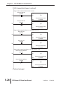
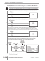
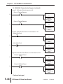
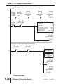
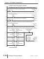
DL MRX/MWX Communication Program (continued)
This rung checks to see if it is time to communicate to slave 2, and also if there
are no current write requests to that drive. If not, it reads data from slave 2.
Drive #2
Speed Ref
Port Busy
Write Enable
SP116
C40
CTA2
K1
=
5
MRX
Drive #2
Drive #2
Direction, Fault, Reset Run CMD
Write Enable
Write Enable
C42
C41
CPU/DCM Slot:
CPU
Port Number:
K2
Slave Address:
K2
Function Code: 03 - Read Holding Registers
Start Slave Memory Address:
K48449
Start Master Memory Address:
V2020
Number of Elements:
K12
Modbus Data type:
584/984 Mode
Exception Response Buffer:
V5003
*** The following 21 rungs (6–26) are for slave 1 communications control. ***
This rung turns on C1 if there is a fault in drive #1.
V2000
K1
욷
6
Drive #1 Fault
C1
( SET )
This rung allows a switch on input X1 to reset the C bit used to indicate a drive #1 fault.
Drive #1 Fault Indication
Reset
X1
Drive #1 Fault
C1
( RST )
7
This rung turns on C2 if drive #1 has an overload fault.
V2000
K4
=
8
This rung allows a switch on input X2 to reset the overload fault bit C2.
Drive #1 Overload Indication
Reset
X2
9
Drive #1 OL
C2
( SET )
Drive #1 OL
C2
( RST )
(Continued next page)
2nd Edition
07/06/2011
GS1 Series AC Drive User Manual
5–39
Chapter 5: GS1 Modbus Communications
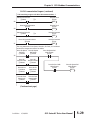
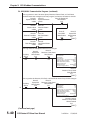
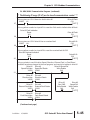
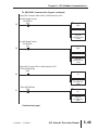
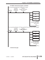
DL MRX/MWX Communication Program (continued)
This rung checks to see if the drive Speed, Direction, External Fault, or Fault Reset
conditions have been changed in the local program, and need to be written to drive #1.
Drive #1 Speed Ref
Drive #1
Drive #1
Write Enable
Speed Ref New
Speed Ref Retain
C10
V3000
V3010
=
10
Drive #1
Direction New
V3002
Drive #1
Direction Retain
V3012
=
Drive #1
External Fault New
V3003
Drive #1
Ext Fault Retain
V3013
Drive #1
Run CMD
Write Enable
C12
=
Drive #1
Fault Reset New
V3004
Drive #1
Speed Ref
Write Enable
C10
( SET )
Drive #1
Fault Reset Retain
V3014
=
This rung writes the new Speed Reference if it changes.
Drive #1
Drive #1
Direction, Fault, Reset
Speed Ref
Write Enable
MWX
Port Busy
Write Enable
CPU/DCM Slot:
C11
SP116
C10
CPU
Port Number:
K2
Slave Address:
K1
Function Code: 06 - Preset Single Register
Start Slave Memory Address:
K42331
Start Master Memory Address:
V3000
Number of Elements:
n/a
Modbus Data type:
584/984 Mode
Exception Response Buffer:
V5006
11
Drive #1
Direction, Fault, Reset
Write Enabled
C11
( SET )
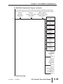
This rung writes the Direction, Ext Fault, and Fault Reset words if any of them changes.
Drive #1
Drive #1
Direction, Fault, Reset
Speed Ref
Write Enable
MWX
Port Busy
Write Enable
CPU/DCM Slot:
CPU
C11
SP116
C10
12
Port Number:
K2
Slave Address:
K1
Function Code: 16 - Preset Multiple Registers
Start Slave Memory Address:
K42333
Start Master Memory Address:
V3002
Number of Elements:
K3
Modbus Data type:
584/984 Mode
Exception Response Buffer:
V5011
Drive #1, Speed,
Direction, Fault, Reset
Writes Finished
C13
( SET )
(Continued next page)
5–40
GS1 Series AC Drive User Manual
2nd Edition
07/06/2011
Chapter 5: GS1 Modbus Communications
DL MRX/MWX Communication Program (continued)
13
This rung writes the new values for Speed Ref, Direction, Ext Fault, and Fault Reset
words to their comparison locations so the code can again start watching for changes.
Drive #1
Drive #1, Speed,
Drive #1
Direction, Fault, Reset Direction, Fault, Reset
Speed Ref
Write Enable
Writes Finished
Write Enable
LD
C11
C13
C10
Drive #1
Speed Ref New
V3000
OUT
Drive #1
Speed Ref Retain
V3010
LD
Drive #1
Direction New
V3002
OUT
Drive #1
Direction Retain
V3012
LD
Drive #1
Ext Fault New
V3003
OUT
Drive #1
Ext Fault Retain
V3013
LD
Drive #1
Fault Reset New
V3004
OUT
Drive #1
Fault Reset Retain
V3014
Drive #1
Speed Ref
Write Enable
C10
( RST )
Drive #1
Direction,
Fault Reset
Write Enable
C11
( RST )
Drive #1
Speed, Direction,
Fault Reset
Writes Finished
C13
( RST )
(Continued next page)
2nd Edition
07/06/2011
GS1 Series AC Drive User Manual
5–41
Chapter 5: GS1 Modbus Communications
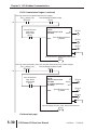
DL MRX/MWX Communication Program (continued)
Rungs 14 & 15 write to the Run Command word if it changes.
Drive #1
Drive #1
Drive #1
Drive #1
Speed Ref
Run CMD
Run CMD
Run CMD
Write Enable
Write Enable
New
Retain
C10
C12
V3001
V3011
Drive #1
Run CMD
Write Enable
C12
( SET )
=
14
Port Busy
SP116
Drive #1
Run CMD
Write Enable
C12
15
MWX
CPU/DCM Slot:
CPU
Port Number:
K2
Slave Address:
K1
Function Code: 06 - Preset Single Register
Start Slave Memory Address:
K42332
Start Master Memory Address:
V3001
Number of Elements:
n/a
Modbus Data type:
584/984 Mode
Exception Response Buffer:
V5014
Drive #1
Run CMD
Writes Finished
C14
( SET )
This rung writes the new value for the Run Command word to its comparison location
so the code can again start watching for changes.
Drive #1
Drive #1
Run CMD
Run CMD
Write Finished
Write Enable
LD
C14
C12
Drive #1
16
Run CMD New
V3001
OUT
Drive #1
Run CMD Retain
V3011
Drive #1
Run CMD
Write Enable
C12
( RST )
Drive #1
Run CMD
Write Finished
C14
( RST )
(Continued next page)
5–42
GS1 Series AC Drive User Manual
2nd Edition
07/06/2011
Chapter 5: GS1 Modbus Communications
DL MRX/MWX Communication Program (continued)
Rungs 17 & 18 select either 30Hz or 60Hz based on X3.
Drive #1 Speed Control
bit 60/30Hz
X3
LD
17
K300
BIN
OUT
Drive #1
Speed Ref New
V3000
Drive #1 Speed Control
bit 60/30Hz
X3
LD
18
K600
BIN
OUT
Drive #1
Speed Ref New
V3000
Rungs 19 & 20 select Run or Stop based on X5.
Drive #1 Run/Stop
X5
LD
19
K1
OUT
Drive #1 Run/Stop
X5
Drive #1
Run CMD New
V3001
LD
20
K0
OUT
Drive #1
Run CMD New
V3001
(Continued next page)
2nd Edition
07/06/2011
GS1 Series AC Drive User Manual
5–43
Chapter 5: GS1 Modbus Communications
DL MRX/MWX Communication Program (continued)
Rungs 21 & 22 select Direction based on X6.
Drive #1 Forward/Reverse
X6
LD
21
K1
OUT
Drive #1 Forward/Reverse
X6
Drive #1
Direction New
V3002
LD
22
K0
OUT
Drive #1
Direction New
V3002
Rungs 23 & 24 select Ext Fault or no fault based on X7.
Drive #1 Ext Fault
X7
LD
23
K1
OUT
Drive #1 Ext Fault
X7
Drive #1
Ext Fault New
V3003
LD
24
K0
OUT
Drive #1
Ext Fault New
V3003
Rungs 25 & 26 select Fault Reset or no reset based on X10.
Drive #1 Ext Fault Reset
X10
LD
25
K1
OUT
Drive #1 Ext Fault Reset
X10
Drive #1
Ext Fault Reset New
V3004
LD
26
K0
OUT
Drive #1
Ext Fault Reset New
V3004
(Continued next page)
5–44
GS1 Series AC Drive User Manual
2nd Edition
07/06/2011
Chapter 5: GS1 Modbus Communications
DL MRX/MWX Communication Program (continued)
*** The following 21 rungs (27–47) are for slave 2 communications control. ***
This rung turns on C31 if there is a fault in drive #2.
V2020
K1
Drive #2 Fault
C31
( SET )
욷
27
This rung allows a switch on input X21 to reset the C bit used to indicate drive #2 fault.
Drive #2 Fault Indication
Reset
X21
Drive #2 Fault
C31
( RST )
28
This rung turns on C32 if drive #2 has an overload fault.
V2020
K4
Drive #2 OL
C32
( SET )
=
29
This rung allows a switch on input X22 to reset the overload fault bit C32.
Drive #2 Overload Indication
Reset
X22
Drive #2 OL
C32
( RST )
30
This rung checks to see if the drive Speed, Direction, External Fault, or Fault Reset
conditions have been changed in the local program, and need to be written to drive #2.
Drive #2
Speed Ref New
V3020
Drive #2
Speed Ref Retain
V3030
Drive #2 Speed Ref
Write Enable
C40
=
31
Drive #2
Direction New
V3022
Drive #2
Direction Retain
V3032
=
Drive #2
External Fault New
V3023
Drive #2
External Fault Retain
V3033
=
Drive #2
Fault Reset New
V3024
Drive #2
Run CMD
Write Enable
C42
Drive #2
Speed Ref
Write Enable
C40
( SET )
Drive #2
Fault Reset Retain
V3034
=
(Continued next page)
2nd Edition
07/06/2011
GS1 Series AC Drive User Manual
5–45
Chapter 5: GS1 Modbus Communications
DL MRX/MWX Communication Program (continued)
This rung writes the new Speed Reference if it changes.
Drive #2
Drive #2
Direction, Fault, Reset
Speed Ref
Write Enable
MWX
Port Busy
Write Enable
CPU/DCM Slot:
C41
SP116
C40
CPU
Port Number:
K2
Slave Address:
K2
Function Code: 06 - Preset Single Register
Start Slave Memory Address:
K42331
Start Master Memory Address:
V3030
Number of Elements:
n/a
Modbus Data type:
584/984 Mode
Exception Response Buffer:
V5017
32
Drive #2
Direction, Fault, Reset
Write Enabled
C41
( SET )
This rung writes the Direction, Ext Fault, and Fault Reset words if any of them changes.
Drive #2
Drive #2
Direction, Fault, Reset
Speed Ref
MWX
Write Enable
Port Busy
Write Enable
CPU/DCM Slot:
CPU
C41
SP116
C40
Port Number:
K2
Slave Address:
K2
Function Code: 16 - Preset Multiple Registers
Start Slave Memory Address:
K42333
Start Master Memory Address:
V3032
Number of Elements:
K3
Modbus Data type:
584/984 Mode
Exception Response Buffer:
V5022
33
Drive #2, Speed,
Direction, Fault, Reset
Writes Finished
C43
( SET )
(Continued next page)
5–46
GS1 Series AC Drive User Manual
2nd Edition
07/06/2011
Chapter 5: GS1 Modbus Communications
DL MRX/MWX Communication Program (continued)
34
This rung writes the new values for Speed Ref, Direction, Ext Fault, and Fault Reset
words to their comparison locations so the code can again start watching for changes.
Drive #2
Drive #2, Speed,
Drive #2
Direction, Fault, Reset Direction, Fault, Reset
Speed Ref
Write Enable
Writes Finished
Write Enable
LD
C41
C43
C40
Drive #2
Speed Ref New
V3020
OUT
Drive #2
Speed Ref Retain
V3030
LD
Drive #2
Direction New
V3022
OUT
Drive #2
Direction Retain
V3032
LD
Drive #2
Ext Fault New
V3023
OUT
Drive #2
Ext Fault Retain
V3033
LD
Drive #2
Fault Reset New
V3024
OUT
Drive #2
Fault Reset Retain
V3034
Drive #2
Speed Ref
Write Enable
C40
( RST )
Drive #2
Direction,
Fault Reset
Write Enable
C41
( RST )
Drive #2
Speed, Direction,
Fault Reset
Writes Finished
C43
( RST )
(Continued next page)
2nd Edition
07/06/2011
GS1 Series AC Drive User Manual
5–47
Chapter 5: GS1 Modbus Communications
DL MRX/MWX Communication Program (continued)
Rungs 35 & 36 write to the Run Command word if it changes.
Drive #2
Drive #2
Drive #2
Drive #2
Speed
Ref
Run
CMD
Run CMD
Run CMD
Write Enable
Write Enable
New
Retain
C40
C42
V3021
V3031
Drive #2
Run CMD
Write Enable
C42
( SET )
=
35
Port Busy
SP116
Drive #2
Run CMD
Write Enable
C42
36
MWX
CPU/DCM Slot:
CPU
Port Number:
K2
Slave Address:
K2
Function Code: 06 - Preset Single Register
Start Slave Memory Address:
K42332
Start Master Memory Address:
V3031
Number of Elements:
n/a
Modbus Data type:
584/984 Mode
Exception Response Buffer:
V5025
Drive #2
Run CMD
Writes Finished
C44
( SET )
37
This rung writes the new value for the Run Command word to its comparison location
so the code can again start watching for changes.
Drive #2
Drive #2
Run CMD
Run CMD
Write Finished
Write Enable
LD
C44
C42
Drive #2
Run CMD New
V3021
OUT
Drive #2
Run CMD Retain
V3031
Drive #2
Run CMD
Write Enable
C42
( RST )
Drive #2
Run CMD
Write Finished
C44
( RST )
(Continued next page)
5–48
GS1 Series AC Drive User Manual
2nd Edition
07/06/2011
Chapter 5: GS1 Modbus Communications
DL MRX/MWX Communication Program (continued)
Rungs 38 & 39 select either 30Hz or 60Hz based on X23.
Drive #2 Speed Control
bit 60/30Hz
X23
LD
38
K300
BIN
OUT
Drive #2
Speed Ref New
V3020
Drive #2 Speed Control
bit 60/30Hz
X23
LD
39
K600
BIN
OUT
Drive #2
Speed Ref New
V3020
Rungs 40 & 41 select Run or Stop based on X25.
Drive #2 Run/Stop
X25
LD
40
K1
OUT
Drive #2
Run CMD New
V3021
Drive #2 Run/Stop
X25
LD
41
K0
OUT
Drive #2
Run CMD New
V3021
(Continued next page)
2nd Edition
07/06/2011
GS1 Series AC Drive User Manual
5–49
Chapter 5: GS1 Modbus Communications
DL MRX/MWX Communication Program (continued)
Rungs 42 & 43 select Direction based on X26.
Drive #2 Forward/Reverse
X26
LD
42
K1
OUT
Drive #2
Direction New
V3022
Drive #2 Forward/Reverse
X26
LD
43
K0
OUT
Drive #2
Direction New
V3002
Rungs 44 & 45 select Ext Fault or no fault based on X27.
Drive #2 Ext Fault
X27
LD
44
K1
OUT
Drive #2
Ext Fault New
V3023
Drive #2 Ext Fault
X27
LD
45
K0
OUT
Drive #2
Ext Fault New
V3023
Rungs 46 & 47 select Fault Reset or no reset based on X30.
Drive #2 Ext Fault Reset
X30
LD
46
K1
OUT
Drive #2
Ext Fault Reset New
V3024
Drive #2 Ext Fault Reset
X30
LD
47
K0
OUT
Drive #2
Ext Fault Reset New
V3024
( END )
48
5–50
GS1 Series AC Drive User Manual
2nd Edition
07/06/2011
Chapter 5: GS1 Modbus Communications
DL RX/WX Communication Program – for DL05, D2-250(-1), D4-450
This program is for illustrational purposes only, and is not intended for a true application.
This rung counts the number of times the PLC attempts to communicate to the drive.
Port Busy
CNT
SP116
1
CT0
K9999
CT0
This rung counts the number of times an attempted communication to the drive fails.
Port Comm Fail
CNT
SP117
2
CT1
K9999
CT1
This rung acts as an alternator, allowing the following logic to alternate between
communicating to slave 1 or slave 2. If there were additional slaves, the ‘K’ number
for the counter would simply be increased to match the number of slaves in the system.
Port Busy
CNT
SP116
3
CT2
K2
CT2
This rung checks to see if it is time to communicate to slave 1, and also if there
are no current write requests to that drive. If not, it reads data from slave 1.
Drive #1
(Slave #1)
Speed Ref
Port Busy
LD
Write Enable
Kf201
SP116
C10
CTA2
K0
=
4
LD
Drive #1
Drive #1
Direction, Fault, Reset Run CMD
Write Enable
Write Enable
C12
C11
LDA
RX
K24
O2000
V20400
(Continued next page)
2nd Edition
07/06/2011
GS1 Series AC Drive User Manual
5–51
Chapter 5: GS1 Modbus Communications
DL RX/WX Communication Program (continued)
This rung checks to see if it is time to communicate to slave 2, and also if there
are no current write requests to that drive. If not, it reads data from slave 2.
Drive #2
(Slave #2)
Speed Ref
Port Busy
LD
Write Enable
Kf202
SP116
C40
CTA2
K1
=
5
Drive #2
Drive #2
Direction, Fault, Reset Run CMD
Write Enable
Write Enable
C42
C41
LD
K24
LDA
RX
O2020
V20400
*** The following 21 rungs (6–26) are for slave 1 communications control. ***
This rung turns on C1 if there is a fault in drive #1.
V2000
K1
6
Drive #1 Fault
C1
( SET )
욷
This rung allows a switch on input X1 to reset the C bit used to indicate a drive #1 fault.
Drive #1 Fault Indication
Drive #1 Fault
Reset
C1
X1
7
( RST )
This rung turns on C2 if drive #1 has an overload fault.
V2000
K4
8
Drive #1 OL
C2
( SET )
=
This rung allows a switch on input X2 to reset the overload fault bit C2.
Drive #1 Overload Indication
Reset
X2
9
Drive #1 OL
C2
( RST )
(Continued next page)
5–52
GS1 Series AC Drive User Manual
2nd Edition
07/06/2011
Chapter 5: GS1 Modbus Communications
DL RX/WX Communication Program (continued)
This rung checks to see if the drive Speed, Direction, External Fault, or Fault Reset
conditions have been changed in the local program, and need to be written to drive #1.
Drive #1
Speed Ref New
V3000
Drive #1
Speed Ref Retain
V3010
Drive #1 Speed Ref
Write Enable
C10
=
10
Drive #1
Direction New
V3002
Drive #1
Direction Retain
V3012
=
Drive #1
External Fault New
V3003
Drive #1
Run CMD
Write Enable
C12
Drive #1
Ext Fault Retain
V3013
=
Drive #1
Fault Reset New
V3004
Drive #1
Speed Ref
Write Enable
C10
( SET )
Drive #1
Fault Reset Retain
V3014
=
This rung writes the new Speed Reference if it changes.
Drive #1
Drive #1
Direction, Fault, Reset
Speed Ref
Write Enable
Port Busy
Write Enable
C11
SP116
C10
11
LD
LD
LDA
WX
Kf201
K2
O3000
V4432
Drive #1
Direction, Fault, Reset
Write Enabled
C11
( SET )
12
This rung writes the Direction, Ext Fault, and Fault Reset words if any of them changes.
Drive #1
Drive #1
Direction, Fault, Reset
Speed Ref
Write Enable
Port Busy
Write Enable
C11
SP116
C10
LD
Kf201
LD
LDA
WX
K6
O3002
V4434
Drive #1 Speed,
Direction, Fault, Reset
Writes Finished
C13
( SET )
(Continued next page)
2nd Edition
07/06/2011
GS1 Series AC Drive User Manual
5–53
Chapter 5: GS1 Modbus Communications
DL RX/WX Communication Program (continued)
13
This rung writes the new values for Speed Ref, Direction, Ext Fault, and Fault Reset
words to their comparison locations so the code can again start watching for changes.
Drive #1
Drive #1, Speed,
Drive #1
Direction, Fault, Reset Direction, Fault, Reset
Speed Ref
Write Enable
Writes Finished
Write Enable
LD
C11
C13
C10
Drive #1
Speed Ref New
V3000
OUT
Drive #1
Speed Ref Retain
V3010
LD
Drive #1
Direction New
V3002
OUT
Drive #1
Direction Retain
V3012
LD
Drive #1
Ext Fault New
V3003
OUT
Drive #1
Ext Fault Retain
V3013
LD
Drive #1
Fault Reset New
V3004
OUT
Drive #1
Fault Reset Retain
V3014
Drive #1
Speed Ref
Write Enable
C10
( RST )
Drive #1
Direction,
Fault Reset
Write Enable
C11
( RST )
Drive #1
Speed, Direction,
Fault Reset
Writes Finished
C13
( RST )
(Continued next page)
5–54
GS1 Series AC Drive User Manual
2nd Edition
07/06/2011
Chapter 5: GS1 Modbus Communications
DL RX/WX Communication Program (continued)
Rungs 14 & 15 write to the Run Command word if it changes.
Drive #1
Drive #1
Drive #1
Drive #1
Speed Ref
Run CMD
Run CMD
Run CMD
Write Enable
Write Enable
New
Retain
C10
C12
V3001
V3011
Drive #1
Run CMD
Write Enable
C12
( SET )
=
14
Port Busy
SP116
Drive #1
Run CMD
Write Enable
C12
15
LD
Kf201
LD
K2
LDA
WX
O3001
V4433
Drive #1
Run CMD
Writes Finished
C14
( SET )
16
This rung writes the new value for the Run Command word to its comparison location
so the code can again start watching for changes.
Drive #1
Drive #1
Run CMD
Run CMD
Write Finished
Write Enable
LD
C14
C12
Drive #1
Run CMD New
V3001
OUT
Drive #1
Run CMD Retain
V3011
Drive #1
Run CMD
Write Enable
C12
( RST )
Drive #1
Run CMD
Write Finished
C14
( RST )
(Continued next page)
2nd Edition
07/06/2011
GS1 Series AC Drive User Manual
5–55
Chapter 5: GS1 Modbus Communications
DL RX/WX Communication Program (continued)
Rungs 17 & 18 select either 30Hz or 60Hz based on X3.
Drive #1 Speed Control
bit 60/30Hz
X3
LD
17
K300
BIN
OUT
Drive #1
Speed Ref New
V3000
Drive #1 Speed Control
bit 60/30Hz
X3
LD
18
K600
BIN
OUT
Drive #1
Speed Ref New
V3000
Rungs 19 & 20 select Run or Stop based on X5.
Drive #1 Run/Stop
X5
LD
19
K1
OUT
Drive #1
Run CMD New
V3001
Drive #1 Run/Stop
X5
LD
20
K0
OUT
Drive #1
Run CMD New
V3001
(Continued next page)
5–56
GS1 Series AC Drive User Manual
2nd Edition
07/06/2011
Chapter 5: GS1 Modbus Communications
DL RX/WX Communication Program (continued)
Rungs 21 & 22 select Direction based on X6.
Drive #1 Forward/Reverse
X6
LD
21
K1
OUT
Drive #1
Direction New
V3002
Drive #1 Forward/Reverse
X6
LD
22
K0
OUT
Drive #1
Direction New
V3002
Rungs 23 & 24 select Ext Fault or no fault based on X7.
Drive #1 Ext Fault
X7
LD
23
K1
OUT
Drive #1
Ext Fault New
V3003
Drive #1 Ext Fault
X7
LD
24
K0
OUT
Drive #1
Ext Fault New
V3003
Rungs 25 & 26 select Fault Reset or no reset based on X10.
Drive #1 Ext Fault Reset
X10
LD
25
K1
OUT
Drive #1
Ext Fault Reset New
V3004
Drive #1 Ext Fault Reset
X10
LD
26
K0
OUT
Drive #1
Ext Fault Reset New
V3004
(Continued next page)
2nd Edition
07/06/2011
GS1 Series AC Drive User Manual
5–57
Chapter 5: GS1 Modbus Communications
DL RX/WX Communication Program (continued)
*** The following 21 rungs (27–47) are for slave 2 communications control. ***
This rung turns on C31 if there is a fault in drive #2.
V2020
K1
27
Drive #2 Fault
C31
( SET )
욷
This rung allows a switch on input X21 to reset the C bit used to indicate drive #2 fault.
Drive #2 Fault Indication
Drive #2 Fault
Reset
C31
X21
28
( RST )
Drive #2 OL
C32
( SET )
This rung turns on C32 if drive #2 has an overload fault.
V2020
K4
29
=
This rung allows a switch on input X22 to reset the overload fault bit C32.
Drive #2 Overload Indication
Drive #2 OL
Reset
C32
X22
30
( RST )
This rung checks to see if the drive Speed, Direction, External Fault, or Fault Reset
conditions have been changed in the local program, and need to be written to drive #2.
Drive #2 Speed Ref
Drive #2
Drive #2
Write Enable
Speed Ref New
Speed Ref Retain
C40
V3020
V3030
=
31
Drive #2
Direction New
V3022
Drive #2
Direction Retain
V3032
=
Drive #2
External Fault New
V3023
Drive #2
External Fault Retain
V3033
=
Drive #2
Fault Reset New
V3024
Drive #2
Run CMD
Write Enable
C42
Drive #2
Speed Ref
Write Enable
C40
( SET )
Drive #2
Fault Reset Retain
V3034
=
(Continued next page)
5–58
GS1 Series AC Drive User Manual
2nd Edition
07/06/2011
Chapter 5: GS1 Modbus Communications
DL RX/WX Communication Program (continued)
This rung writes the new Speed Reference if it changes.
Drive #2
Drive #2
Direction, Fault, Reset
Speed Ref
Write Enable
Port Busy
Write Enable
C41
SP116
C40
32
LD
LD
LDA
WX
Kf202
K2
O3000
V4432
Drive #2
Direction, Fault, Reset
Write Enabled
C41
( SET )
33
This rung writes the Direction, Ext Fault, and Fault Reset words if any of them changes.
Drive #2
Drive #2
Direction, Fault, Reset
Speed Ref
Write Enable
Port Busy
Write Enable
C41
SP116
C40
LD
Kf202
LD
LDA
WX
K6
O3002
V4434
Drive #2, Speed,
Direction, Fault, Reset
Writes Finished
C43
( SET )
(Continued next page)
2nd Edition
07/06/2011
GS1 Series AC Drive User Manual
5–59
Chapter 5: GS1 Modbus Communications
DL RX/WX Communication Program (continued)
34
This rung writes the new values for Speed Ref, Direction, Ext Fault, and Fault Reset
words to their comparison locations so the code can again start watching for changes.
Drive #2
Drive #2, Speed,
Drive #2
Direction, Fault, Reset Direction, Fault, Reset
Speed Ref
Write Enable
Writes Finished
Write Enable
LD
C41
C43
C40
Drive #2
Speed Ref New
V3020
OUT
Drive #2
Speed Ref Retain
V3030
LD
Drive #2
Direction New
V3022
OUT
Drive #2
Direction Retain
V3032
LD
Drive #2
Ext Fault New
V3023
OUT
Drive #2
Ext Fault Retain
V3033
LD
Drive #2
Fault Reset New
V3024
OUT
Drive #2
Fault Reset Retain
V3034
Drive #2
Speed Ref
Write Enable
C40
( RST )
Drive #2
Direction,
Fault Reset
Write Enable
C41
( RST )
Drive #2
Speed, Direction,
Fault Reset
Writes Finished
C43
( RST )
(Continued next page)
5–60
GS1 Series AC Drive User Manual
2nd Edition
07/06/2011
Chapter 5: GS1 Modbus Communications
DL RX/WX Communication Program (continued)
Rungs 35 & 36 write to the Run Command word if it changes.
Drive #2
Drive #2
Drive #2
Drive #2
Speed Ref
Run CMD
Run CMD
Run CMD
Write Enable
Write Enable
New
Retain
C40
C42
V3021
V3031
Drive #2
Run CMD
Write Enable
C42
( SET )
=
35
Port Busy
SP116
Drive #2
Run CMD
Write Enable
C42
36
LD
Kf202
LD
K2
LDA
WX
O3001
V4433
Drive #2
Run CMD
Writes Finished
C44
( SET )
37
This rung writes the new value for the Run Command word to its comparison location
so the code can again start watching for changes.
Drive #2
Drive #2
Run CMD
Run CMD
Write Finished
Write Enable
LD
C44
C42
Drive #2
Run CMD New
V3021
OUT
Drive #2
Run CMD Retain
V3031
Drive #2
Run CMD
Write Enable
C42
( RST )
Drive #2
Run CMD
Write Finished
C44
( RST )
(Continued next page)
2nd Edition
07/06/2011
GS1 Series AC Drive User Manual
5–61
Chapter 5: GS1 Modbus Communications
DL RX/WX Communication Program (continued)
Rungs 38 & 39 select either 30Hz or 60Hz based on X23.
Drive #2 Speed Control
bit 60/30Hz
X23
LD
38
K300
BIN
OUT
Drive #2
Speed Ref New
V3020
Drive #2 Speed Control
bit 60/30Hz
X23
LD
39
K600
BIN
OUT
Drive #2
Speed Ref New
V3020
Rungs 40 & 41 select Run or Stop based on X25.
Drive #2 Run/Stop
X25
LD
40
K1
OUT
Drive #2
Run CMD New
V3021
Drive #2 Run/Stop
X25
LD
41
K0
OUT
Drive #2
Run CMD New
V3021
(Continued next page)
5–62
GS1 Series AC Drive User Manual
2nd Edition
07/06/2011
Chapter 5: GS1 Modbus Communications
DL RX/WX Communication Program (continued)
Rungs 42 & 43 select Direction based on X26.
Drive #2 Forward/Reverse
X26
LD
42
K1
OUT
Drive #2
Direction New
V3022
Drive #2 Forward/Reverse
X26
LD
43
K0
OUT
Drive #2
Direction New
V3002
Rungs 44 & 45 select Ext Fault or no fault based on X27.
Drive #2 Ext Fault
X27
LD
44
K1
OUT
Drive #2
Ext Fault New
V3023
Drive #2 Ext Fault
X27
LD
45
K0
OUT
Drive #2
Ext Fault New
V3023
Rungs 46 & 47 select Fault Reset or no reset based on X30.
Drive #2 Ext Fault Reset
X30
LD
46
K1
OUT
Drive #2
Ext Fault Reset New
V3024
Drive #2 Ext Fault Reset
X30
LD
47
K0
OUT
Drive #2
Ext Fault Reset New
V3024
( END )
48
(Continued next page)
2nd Edition
07/06/2011
GS1 Series AC Drive User Manual
5–63
Chapter 5: GS1 Modbus Communications
Communicating with Third-Party Devices
The GS1 Serial Comm Port will accommodate an RS-485 connection.
An RS-485 network cable can span up to 1000 meters (3280 feet). The GS1 AC
drive communication address is specified by P9.00. The third party device then
controls each AC drive according to its communication address.
The GS1 series AC drive can be set up to communicate on standard MODBUS
networks using the following transmission modes: ASCII or RTU. Using the
Communication Protocol parameter (P9.02), you can select the desired mode,
data bits, parity, and stop bits. The mode and serial parameters must be the same
for all devices on a MODBUS network.
GS1 RS-485 Serial Comm Port
GS1 Serial Comm Port
RS-485 Interface
RJ12 (6P4C)
6
1
1:
2:
3:
4:
5:
6:
+17V
GND
SGSG+
nc
reserved
GS1 drives have a provision for shutting down control or power to the inverter in the
event of a communications time out. This feature can be set up through parameters
P9.03, P9.04, and P9.05.
Common Third-Party MODBUS RTU Masters
• MODSCAN from www.wintech.com
• KEPSERVER EX 4.0 from www.kepware.com
• Entivity Studio 7.2
• Think & Do Live 5.5.1
For additional technical assistance, go to our Technical support home page at:
http://support.automationdirect.com/technotes.html
5–64
GS1 Series AC Drive User Manual
2nd Edition
07/06/2011
Chapter 5: GS1 Modbus Communications
Using Modbus ASCII
Data Format
ASCII Mode: 10-bit character frame (For 7-bit character):
P9.02 = 00 (7 data bits, no parity, 2 stop bits)
Start
bit
0
1
2
3
4
5
6
Stop Stop
bit
bit
7-bit character
10-bit character frame
P9.02 = 01 (7 data bits, even parity, 1 stop bit)
Start
bit
0
1
2
3
4
5
6
Even Stop
parity bit
5
6
Odd Stop
parity bit
7-bit character
10-bit character frame
P9.02 = 02 (7 data bits, odd parity, 1 stop bit)
Start
bit
0
1
2
3
4
7-bit character
10-bit character frame
RTU Mode: 11-bit character frame (For 8-bit character):
P9.02 = 03 (8 data bits, no parity, 2 stop bits)
Start
bit
0
1
2
3
4
5
6
7
Stop
bit
Stop
bit
6
7
Even Stop
parity bit
6
7
Odd Stop
parity bit
8-bit character
11-bit character frame
P9.02 = 04 (8 data bits, even parity, 1 stop bit)
Start
bit
0
1
2
3
4
5
8-bit character
11-bit character frame
P9.02 = 05 (8 data bits, odd parity, 1 stop bit)
Start
bit
0
1
2
3
4
5
8-bit character
11-bit character frame
2nd Edition
07/06/2011
GS1 Series AC Drive User Manual
5–65
Chapter 5: GS1 Modbus Communications
Communication Protocol
ASCII Mode:
STX
Start Character: (3AH)
ADR 1
ADR 0
CMD 1
Communication Address: 8-bit address consists of 2 ASCII codes
CMD 0
DATA (n-1)
.......
DATA 0
LRC CHK 1
LRC CHK 0
END 1
END 0
Contents of data: n x 8-bit data consists of 2n ASCII codes.
n ≤ 25 maximum of 50 ASCII codes
LRC check sum: 8-bit check sum consists of 2 ASCII codes
END characters: END 1 = CR (0DH); END 0 = LF (0AH)
RTU Mode:
START
A silent interval of more than 10 ms
ADR
Communication Address: 8-bit address
CMD
Command Code: 8-bit command
DATA (n-1)
Contents of data: n x 8-bit data, n ≤ 25
.......
DATA 0
CRC CHK Low
CRC CHK High
CRC check sum: 16-bit check sum consists of 2 8-bit characters
END
A silent interval of more than 10 ms
ADR (Communication Address)
Valid communication addresses are in the range of 0 to 254. A communication
address equal to 0 means broadcast to all AC drives, in which case the drives will
not reply any message to the master device.
For example, communication to AC drive with address 16 decimal:
ASCII mode: (ADR 1, ADR 0)='1','0' => '1'=31H, '0'=30H
RTU mode: (ADR)=10H
5–66
GS1 Series AC Drive User Manual
2nd Edition
07/06/2011
Chapter 5: GS1 Modbus Communications
CMD (Command code) and DATA (data characters)
The format of data characters depends on the command code. The available
command codes are described as follows: Command code: 03H, read N words.
The maximum value of N is 12. For example, reading continuous 2 words from
starting address 2102H of the AC drive with address 01H.
ASCII mode:
Command Message
Response Message
STX
':'
STX ':'
':'
ADR 1
ADR 0
'0'
ADR 1
ADR 0
'0'
CMD 1
CMD 0
'0'
CMD 1
CMD 0
'0'
Number of data
(Count by byte)
'0'
'1'
'3'
'2'
Starting data
address
'1'
'0'
'3'
'4'
'1'
Content of starting
data address
2102H
'2'
'0'
Number of data
(Count by word)
'1'
'7'
'7'
'0'
'0'
'0'
'0'
'2'
LRC CHK 1
LRC CHK 0
'D'
END 1
END 0
CR
Content data
address 2103H
'7'
'0'
'0'
'0'
LF
LRC CHK 1
LRC CHK 0
'7'
END 1
END 0
CR
'1'
LF
RTU mode:
Command Message
2nd Edition
07/06/2011
Response Message
ADR
01H
ADR
01H
CMD
03H
CMD
03H
Starting data
address
21H
Number of data
(Count by byte)
04H
Number of data
(Count by word)
00H
Content of data
address 2102H
17H
CRC CHK Low
CRC CHK High
6FH
Content of data
address 2103H
00H
CRC CHK Low
CRC CHK High
FEH
02H
02H
F7H
'0'
70H
02H
5CH
GS1 Series AC Drive User Manual
5–67
Chapter 5: GS1 Modbus Communications
Command code: 06H, write 1 word
For example, writing 6000(1770H) to address 0100H of the AC drive with address
01H.
ASCII mode:
Command Message
Response Message
STX
':'
STX ':'
':'
ADR 1
ADR 0
'0'
ADR 1
ADR 0
'0'
CMD 1
CMD 0
'0'
CMD 1
CMD 0
'0'
'1'
'6'
'0'
'1'
'0'
Data Address
'1'
'6'
'0'
Data Address
'1'
'0'
'0'
'0'
'1'
'1'
'7'
'7'
Data Content
'0'
LRC CHK 1
LRC CHK 0
'7'
END 1
END 0
CR
'1'
LF
'7'
'7'
'0'
LRC CHK 1
LRC CHK 0
'7'
END 1
END 0
CR
'1'
LF
RTU mode:
This is an example of using function code 16 for writing to multiple registers.
Command Message
ADR
01H
ADR
01H
CMD
10H
CMD
10H
Starting data
address
20H
Starting data
address
20H
Number of data
(Count by word)
00H
CRC CHK Low
CRC CHK High
4AH
Number of registers
5–68
Response Message
00H
00H
02H
Byte count
04H
Content of data
address 2000H
00H
Content of data
address 2001H
02H
CRC CHK Low
CRC CHK High
CBH
00H
02H
08H
02H
58H
34H
GS1 Series AC Drive User Manual
2nd Edition
07/06/2011
Chapter 5: GS1 Modbus Communications
CHK (check sum)
ASCII Mode:
LRC (Longitudinal Redundancy Check) is calculated by summing up module 256,
the values of the bytes from ADR1 to last data character, then calculating the
hexadecimal representation of the 2's-complement negation of the sum.
For example, reading 1 word from address 0401H of the AC drive with address 01H.
Command Message
STX
':'
ADR 1
ADR 0
'0'
CMD 1
CMD 0
'0'
'1'
'3'
'0'
Starting data
address
'4'
'0'
'1'
'0'
Number of data
(Count by word)
'0'
01H+03H+04H+01H+00H+01H=0AH;
the 2's complement negation of 0AH is F6H.
'0'
'1'
LRC CHK 1
LRC CHK 0
END 1
END 0
'F'
'6'
CR
LF
RTU Mode:
Response Message
2nd Edition
ADR
01H
CMD
03H
Starting data
address
21H
Number of data
(Count by word)
00H
CRC CHK Low
CRC CHK High
6FH
07/06/2011
02H
02H
F7H
GS1 Series AC Drive User Manual
5–69
Chapter 5: GS1 Modbus Communications
CRC (Cyclical Redundancy Check) is calculated by the following steps:
Step 1: Load a 16-bit register (called CRC register) with FFFFH.
Step 2: Exclusive OR the first 8-bit byte of the command message with the low order
byte of the 16-bit CRC register, putting the result in the CRC register.
Step 3: Shift the CRC register one bit to the right with MSB zero filling. Extract and
examine the LSB.
Step 4: If the LSB of CRC register is 0, repeat step 3; else Exclusive OR the CRC
register with the polynomial value A001H.
Step 5: Repeat step 3 and 4 until eight shifts have been performed. When this is
done, a complete 8-bit byte will have been processed.
Step 6: Repeat steps 2 to 5 for the next 8-bit byte of the command message.
Continue doing this until all bytes have been processed. The final contents of the
CRC register are the CRC value.
When transmitting the CRC value in the message, the upper and lower bytes of the
CRC value must be swapped; i.e., the lower-order byte will be transmitted first.
The following is an example of CRC generation using C language. The function
takes two arguments:
Unsigned char* data ← a pointer to the message buffer
Unsigned char length ← the quantity of bytes in the message buffer
The function returns the CRC value as a type of unsigned integer.
Unsigned int crc_chk(unsigned char* data, unsigned char length){
int j;
unsigned int reg_crc=0xFFFF;
while(length--){
reg_crc ^= *data++;
for(j=0;j<8;j++){
if(reg_crc & 0x01){ /* LSB(b0)=1 */
reg_crc=(reg_crc>>1) ^ 0xA001;
}else{
reg_crc=reg_crc >>1;
}
}
}
return reg_crc;
}
RTU mode is preferred. Limited support is available to ASCII users.
5–70
GS1 Series AC Drive User Manual
2nd Edition
07/06/2011
Chapter 5: GS1 Modbus Communications
Comm Delay – Optimizing Communications
Optimizing Communications to GS Drives
In most cases, optimizing communications to GS Drives MAY NOT BE NECESSARY.
If you are only communicating to one or two drives and reading or writing only a
few parameters, the communication speed will most likely be sufficient for your
application.
However, in the case that the communication speed (reaction time from reading
or writing an event to a given drive) is too slow, you may need to take a more
detailed look at how your code is designed to communicate to the GS Drives in
your application.
To properly design the system, it is necessary to understand all of the propagation
delays that are incurred when triggering the event to send a Modbus message to
the point of receiving the data or status of the reply into the PLC or Modbus
master.
To determine the time necessary to transmit a message from the Master to the
Slave and vice versa, we must first determine the “Bit Time” and the “Character
Time”. This is calculated by using the following formulas:
• Bit Time:
The value one divided by the baud rate. A baud rate of 19,200 equals a bit rate of
0.0000528 (1/19200) or 52 µs (microseconds).
• Character Time:
Bit Time multiplied by the number of bits. With Modbus this is typically 10–12
bits per character [1 start bit (fixed), 1 or 2 stop bits (usually configurable), 0 or 1
parity bit (Odd & Even = 1 bit; None = 0), & 8 data bits]. For a setting of Odd
parity and 1 Stop bit, this would be 11 bits. So at 19200, Odd parity and 1 stop
bit, a character time would be 0.000573 or 573 µs (0.0000528 · 11).
Now that we know the byte time, we can multiply that time by the number of
characters in each message.
2nd Edition
07/06/2011
GS1 Series AC Drive User Manual
5–71
Chapter 5: GS1 Modbus Communications
Types of Messages Sent to GS Drives
There are three different types of messages typically be sent to GS Drives:
1) Read Registers (Function Code 3).
2) Write Multiple Registers (Function Code 16).
3) Write Single Register (Function Code 6).
Format of “Read Registers” Messages:
Request:
XX = Node Address (1 Char)
03 = Function Code (1 Char)
XXXX = Starting Address to read (2 Chars)
XXXX = Number of Registers to read (2 Chars)
XXXX = 16 Bit CRC (2 Chars)
Reply:
XX = Node Address (1 Char)
03 = Function Code (1 Char)
XX = Byte count of data being sent from Slave
(1 Char)
XXXX… = Depends upon Request
(2 Chars per Register requested)
XXXX = 16 Bit CRC (2 Chars)
Format of “Write Multiple Registers” Messages:
Request:
XX = Node Address (1 Char)
10 = Function Code (Hex format) (1 Char)
XXXX = Starting Address to write to (2 Chars)
XXXX = Number of Registers to write to
(2 Chars)
XX = Number of bytes of data to write
(1 Char)
XXXX… = Depends upon Request
(2 Chars per Register requested)
XXXX = 16 Bit CRC (2 Chars)
Reply:
XX = Node Address (1 Char)
10 = Function Code (Hex format)(1 Char)
XXXX = Starting Address to write to (2 Chars)
XXXX = Number of Registers to write to
(2 Chars)
XXXX = 16 Bit CRC (2 Chars)
Format of “Write Single Register” Messages:
Request:
XX = Node Address (1 Char)
06 = Function Code (1 Char)
XXXX = Register to Write to (2 Chars)
XXXX = Data to Write (2 Chars)
XXXX = 16 Bit CRC (2 Chars)
Reply:
XX = Node Address (1 Char)
06 = Function Code (1 Char)
XXXX = Register to Write to (2 Chars)
XXXX = Data to Write (2 Chars)
XXXX = 16 Bit CRC (2 Chars)
Example Message:
Write a value of 60Hz to P9.26 and a value of 1 to P9.27 =
01 10 09 1b 00 02 04 02 58 00 01 5a 66
We receive a good reply = 01 10 09 1b 00 02 a3 9f
Sending message (13 characters from above) = 7.4 ms (0.00744796)
Reply message (8 characters from above) = 4.6 ms (0.004583)
For more specific information on how Modbus messages are formed, refer to the
Modbus specifications found at www.modbus.org.
5–72
GS1 Series AC Drive User Manual
2nd Edition
07/06/2011
Chapter 5: GS1 Modbus Communications
Additional Message Delay Times
So we have the total transmission time for sending a message and receiving a
reply but this does not include all of the delays for a given message. The
receiving device must have time to process the receipt of a message and formulate
a reply. The amount of time that the receiving device needs will vary greatly
depending upon the hardware platform and other processes that the device is
running.
For the previous example message, the GS Drive responds in 4ms when the drive
is stopped and will respond in 5ms when the drive is running. This may vary
somewhat depending upon the specific parameter values and the size of the
request.
Modbus-specified Delays Between Messages
There is one additional time delay required in the Modbus protocol. The protocol
specifies at least a 3.5 character delay between messages. For the settings above,
a 3.5 character time in our example would be about 2ms.
So the total time required for the message sent above would be:
7.4 ms (Transmission time for sending message)
5.0 ms (response delay from GS Drive when drive running)
4.6 ms (Transmission time for reply message)
+ 2.0 ms (Modbus message wait delay)
19.0 ms (approximately)
Remember from our description, this is purely the time from when the message
leaves the serial port to when the reply is received back in to the serial port.
2nd Edition
07/06/2011
GS1 Series AC Drive User Manual
5–73
Chapter 5: GS1 Modbus Communications
Other Delays
Depending upon the master device, there may be additional delays. For example:
In the DirectLogic PLC, the serial communications are serviced in the
housekeeping portion of the PLC scan. So if the communications instruction is in
rung #1 of a ladder program, the serial communications message does not get
sent until the end of the total PLC scan. Likewise, if the reply message was
received into the serial port at the beginning of the PLC scan, it would not be
serviced until the end of the PLC scan.
So you would need to add an additional possible two PLC scan times to the
number above to truly calculate the time necessary to read or write an event to
the GS drive.
These delays are shown in the following Communication Delay Timing Diagram.
Communication Delay Timing Diagram
Modbus Master
(typically PLC)
GS AC
Drive
Total Delay for Reading/Writing an Event
Communications
Instruction Enabled
t1
t2
t3
t4
t5
t6
5–74
t1 = Scan delay from the point of turning on a
communications instruction to when it actually goes
out of the serial port.
t2 = Transmission time to send Message request
(read or write).
t3 = Response delay from GS drive to receive the reply
and formulate the response.
t4 = Transmission time to send Reply message.
t5 = Scan delay from the point of receiving reply,
processing it and placing in PLC memory for Logic
usage.
t6 = Wait time required by Modbus spec (3.5 byte times).
This may or may not be present depending upon the
Scan delay, but safer to factor in.
Data Processed and
Available to Logic
GS1 Series AC Drive User Manual
2nd Edition
07/06/2011
Chapter 5: GS1 Modbus Communications
Communication Delay Summary
Now that you know how to calculate the time required for one message to one
GS drive, you would simply multiply this value per message to each GS drive on
the network, since only one message can be sent at a time.
As you can deduce from the statement above, the more messages being sent to
GS drives, the longer it takes to communicate to an individual drive as each
message has to take its turn.
So how do you optimize your communications to get messages faster to your GS
drives?
There is no way to make a message go faster than what is specified above, but
what you can affect is the amount of messages being sent to any given GS drive in
two ways.
1) Group together messages into Block requests whenever possible. For example, if
you wanted to read Status Monitor 1 and the Output Frequency status register
from the drive, read the two together as a block (Status Monitor 1, Status Monitor
2, Frequency Command and Output Frequency), and ignore the other two status
registers that you don’t need instead of sending two separate read commands. If
you do the calculations above, you will see that is much faster to take the
additional hit from four extra bytes in the reply message than it would be to send
a separate message. NOTE that you cannot read across non-contiguous Modbus
addresses, so this typically only works when reading within the Status registers or
in a Parameter category (P9.xx, P1.xx, etc…).
2) Only send a write message when the value changes in the Master device. It is
simpler to setup your communications instructions to read and write all the time,
but it wastes precious network time to write the same value to the GS drive over
and over if that value is not changing. Write some simple logic that only triggers a
write command when the value to be sent has changed.
For more specific instructions on how to configure and/or interlock, in detail, the
individual communications instructions, consult your PLC or Modbus Master
Device user manual. If using DirectLogic PLCs as the Modbus Master, consult the
Dx-USER-M manuals for specifics on configuring the individual communications
instructions and look at the Hx-ECOM-M manual for information on interlocking
communications instructions.
2nd Edition
07/06/2011
GS1 Series AC Drive User Manual
5–75
Chapter 5: GS1 Modbus Communications
5–76
GS1 Series AC Drive User Manual
2nd Edition
07/06/2011