1
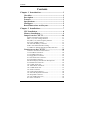
Contents
Contents
Chapter 1 Introduction............................................. 1
Checklist..................................................................... 2
Description ................................................................. 2
Features ...................................................................... 3
Specifications ............................................................. 3
Intelligence ................................................................. 5
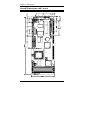
Board Dimensions and Layout................................. 6
Chapter 2 Installations ............................................. 7
CPU Installation ........................................................ 8
Memory Installation.................................................. 9
Jumpers on the CI5TTV......................................... 10
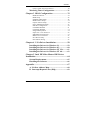
Jumper Locations on the CI5TTV......................................11
SW1 (1-4): CPU Voltage Selector .....................................12
JP6, SW3 (1-4):CPU Frequency Selector ..........................13
JP5: Clear CMOS Content .................................................15
J18: External Battery Connector ........................................16
JPW1: LCD Panel Interface Setting ...................................16
J7, JPW2/3/4: RS232/422/485 (COM2) Selection.............17
Connectors on the CI5TTV .................................... 18
Connector Locations on the CI5TTV .................................19
J1: Front Bezel Connector..................................................20
J3, J4: EIDE Connectors ....................................................22
J5: Floppy Drive Connector ...............................................23
J6: CPU Fan Power Connector...........................................23
J8: LCD Panel Connector...................................................24
Flat Panel Display Interface Pin Descriptions ....................25
J9: Parallel Port Connector.................................................26
J10: COM1 Serial Port .......................................................27
J11: PS/2 Mouse Connector ...............................................27
J12: COM2 Serial Port .......................................................27
J13: IrDA Connector ..........................................................27
J14: VGA CRT Connector .................................................28
J15: External Keyboard Connector ....................................28
J16: Keyboard Connector...................................................28
J19, J20: USB Connectors..................................................29
P1: Power Connector..........................................................29
iv
CI5TTV User’s Manual