1
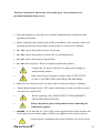
NanoScanZ Nanopositioning Piezo Z Stage System OPERATING MANUAL P RIOR S CIENTIFIC I NC ., 80 R ES E RV O I R P A R K D R I V E R O C K L A N D , MA 02370-1062 T ELE PHONE 781-878-8442 F A X 781-878-8736 W E B S I T E : W W W. P R I O R . C O M q~ÄäÉ=çÑ=`çåíÉåíë= Important Safety Information Section 1 ................. 3 General Information Section 2 .......................... 7 2.1 Before you begin. 8 2.2 Handling the Prior NanoScanZ. 8 2.3 Description of parts. 10 Unpacking The System Section 3 ........................ 14 3..1 List of Supplied parts: 15 Installation Section 4 ................................ 16 4.1 Installing the sample holder into the NZ400. 18 4.2 Installing the NZ400 NanoScanZ Stage. 19 4.3 Installing the NZ400 NanoScanZ Stage onto the manual stage adaptor. 19 4.4 Installing the sample holder into the NZ400. 20 4.5 Installing the NZ400 NanoScanZ Stage. 21 4.6 Installing the NZ400 NanoScanZ Stage onto the manual adaptor. 22 4.7 The NanoScanZ Controller: 23 4.8 Connecting the NanoScanZ stage to the controller. 25 Getting Started Section 5 ............................. 26 5.1 Switching on your NanoScanZ system. 27 5.2 Care during operation 29 5.3 Using the additional analogue Input control: 29 Advanced Operation Section 6 .......................... 31 6.1 Connecting your system via USB Operation 32 6.2 RS232 Command Set 34 6.3 Error Codes 37 Troubleshooting Section 7 ............................. 38 7.1 Troubleshooting 39 System Specifications Section 8 ....................... 40 7.1 Specifications 41 Replacement Parts Section 9 ........................... 42 NanoScanZ™ 1 = 2 Prior Scientific fãéçêí~åí=p~ÑÉíó=fåÑçêã~íáçå= NanoScanZ™ pÉÅíáçå=N= 3 Important Safety Information Definition of Warnings: Danger Electrical Shock hazard. Warning read instructions to determine possible hazard. Caution: Read these operating instructions fully before use and pay particular attention to sections containing this symbol. Use only as specified by the operating instructions or the intrinsic protection may be impaired. Warnings: The following symbols are found on the front of the NanoScanZ controller above the Z stage connector. The high voltage drivers can produce hazardous voltages and currents. Use caution when operating the drivers and when handling the linear actuators. Piezoactuators have large capacitance and are capable of storing hazardous amounts of electrical energy over long periods of time. Various conditions such as load and temperature changes can also cause piezoactuators to accumulate charge. Before disconnecting the DB-9 connector from the NanoScanZ: 1. Set the command voltage to 0.0V. 2. Turn the AC power to the NanoScanZ off. 3. Wait a minimum of one minute before disconnecting. 4 Prior Scientific The Prior NanoScanZ has no user serviceable parts. Only trained service personnel should perform service. • Keep this manual in a safe place as it contains important safety information and operating instructions. • Before using the stage system, please follow and adhere to all warnings, safety and operating instructions located either on the product or in this User’s Manual. • Do not expose the product to water or moisture. • Do not expose the product to extreme hot or cold temperatures. • Do not expose the product to open flames. • Do not allow objects to fall on or liquids to spill on the product. • Connect the AC power cord only to a mains power supply as marked on the product. • Only connect to an earth power supply socket. THIS UNIT IS CLASS 1 CONTRUCTION AND MUST BE EARTHED! • • Make sure the electrical cord is located so that it will not be subject to damage. Ensure that the mains switch / IEC socket/ mains plug is easily accessible to allow the unit to be switched off. • Before replacing a fuse, DISCONNECT THE EQUIPMENT FROM THE MAINS SUPPLY. • Always disconnect power from product before connecting the components together. • DANGER - never alter the AC cord or plug. If the supplied cord set does not have the correct plug for your mains supply, contact your supplier for the correct cord set. • Ensure that the ventilations slots in the controller case are free from NanoScanZ™ 5 obstruction. • Use only the power supply cord set provided with the system for this unit, should this not be correct for your geographical area, contact your supplier. • Do not in any way attempt to tamper with the product, doing so will void the warranty, and may damage the system. This product does not contain consumer serviceable components, all repairs or services should be performed by Authorised Service Centres, contact your local dealer for details. • This product is designed to comply with BSEN 61010-1 and can be flash tested. It is fitted with radio frequency interference suppressors. Therefore it is recommended that only a D.C. test be performed. Performing flash tests repeatedly can damage insulation. 6 Prior Scientific dÉåÉê~ä=fåÑçêã~íáçå= NanoScanZ™ pÉÅíáçå=O= 7 General Information The Prior NanoScanZ includes a PZT actuated linear peizo stage of exceptional resolution and stability and comes complete with a position sensitive detector for closed loop operation.. The Prior NanoScanZ stage inserts directly into the Prior microscope range of stages and has a large through hole that accepts a range of specialised Prior sample holders. 2.1 Before you begin. Before unpacking the Prior NanoScanZ read this entire operation manual, paying special attention to the following section on “Handling the Prior NanoScanZ”, and the safety information in Section 1. Check the contents of the package against the shipping list and notify your vendor immediately if any items are missing. 2.2 Handling the Prior NanoScanZ. The Prior NanoScanZ is a high precision scientific instrument and therefore requires special handling in order to ensure proper operation. Mishandling can cause permanent damage to the NanoScanZ stage. To ensure a long and useful life the following guidelines should be strictly followed. • Do not lift by the cable, always lift by the stage frame (outer portion). • Do not drop, treat roughly, or physically shock the NanoScanZ stage. • Do not move the translation stage by pushing on it with your hands or any other object. • Avoid applying a torque between the moving stage and the frame. • Always mount the Prior NanoScanZ on a flat and clean surface. • Ensure the underside of the Prior NanoScanZ is free of particles and dust before mounting. 8 Prior Scientific • Do not immerse in any liquid. If the Prior NanoScanZ requires cleaning slightly dampen a lint free cloth with iso-propanol or ethanol and lightly wipe the surface. Do not get any liquid or lint into the EDM grooves. • Never disassemble the NanoScanZ stage, there are no user serviceable parts inside. • Do not plug the RS232 connector into the stage socket, this is likely to cause severe damage to you computer. NanoScanZ™ 9 2.3 Description of parts. Please take time to identify each of the parts supplied with your NanoScanZ system. Controller Box: NanoScanZ Stage: 10 Prior Scientific NanoScanZ Stage (400um): NanoScanZ™ 11 NanoScanZ Stage Inserts: NZ301XR: NZ302XR: 12 Prior Scientific NZ303XR: RS232 Cable USB Cable Please ensure all parts have arrived in the original packaging and have not suffered any damaged during transit. Should any part be damaged on initial inspection, report this to your local vendor immediately. NanoScanZ™ 13 råé~ÅâáåÖ=qÜÉ=póëíÉã= 14 pÉÅíáçå=P= Prior Scientific Unpacking The System The NanoScanZ System consists of the NanoScanZ Controller, the NanoScanZ Stage an RS232 Cable, an USB cable, a Prior Software CD, and one or more of the following stage inserts and adaptor plates. 3..1 List of Supplied parts: NZ400: A: NZ301XR – Well Plate Holder Insert. B: NZ302XR – Universal Holder Insert. C: NZ303XR – Slide Holder Insert. EMIPZ3 - Adaptor Plate for H101A upright stages. EMIPZ5 - Adaptor Plate for Olympus and Zeiss inverted manual stages. NanoScanZ™ 15 fåëí~ää~íáçå= 16 pÉÅíáçå=Q= Prior Scientific Installation Install the XY Stage onto your microscope before installing the NanoScanZ stage, the NanoScanZ must be installed horizontally. When planning to install the stage minimise the load carried by the NanoScanZ stage. Heavier loads reduce the stage response time and may cause fatigue and/or reduced motion. Install the sample holder into the NanoScanZ stage before installing onto the XY stage. NanoScanZ™ 17 4.1 Installing the sample holder into the 1= To attach the Prior sample holder into the NanoScanZ Stage, use the following procedure: Equipment required: Prior NanoScanZ, Prior NanoScanZ sample holder, 4 M2 Screws, Lint free cloth. • Using a lint free cloth, gently wipe off the top of the Prior NanoScanZ and the Prior sample holder to remove any particles or dust. • Using a lint free cloth, gently wipe the underside of the sample holder to remove any particles or dust. • Gently place the Prior sample holder into the cut out on the Prior NanoScanZ. 4 M2 Screws • Secure the Prior sample holder by alternately and evenly tightening the four captive screws, while making sure that no torque is applied between the outer frame and inner stage. 18 Prior Scientific 4.2 Installing the 1=1DQR6FDQ=6WDJH To install the Prior NanoScanZ in a motorised XY Stage use the following steps: Equipment required: NanoScanZ Stage (with sample holder installed), lint free cloth, small screw driver, Motorized stage, installed on microscope. • Using a lint free cloth gently wipe the bottom of the Prior NanoScanZ and the top of the Prior microscope stage to remove any particles or dust. • Gently place the Prior NanoScanZ into the cut out on the Prior microscope stage, handling by the outer frame only. • Secure the Prior NanoScanZ by alternately and evenly tightening the four M3 screws. 4 M3 Screws 4.3 Installing the 1= NanoScanZ Stage onto the manual stage adaptor. To install the Prior NanoScanZ on a Manual Olympus or Nikon XY Stage use the following steps: Equipment required: NanoScanZ™ 19 NanoScanZ Stage (with sample holder installed), lint free cloth, small screw driver, manual stage, installed on microscope, adaptor plate. • Place adaptor plate onto manual stage and secure with four screws provided. • Using a lint free cloth gently wipe the bottom of the Prior NanoScanZ and the top of the adaptor plate to remove any particles or dust. • Gently place the Prior NanoScanZ into the cut out on the adaptor plate, handling by the outer frame only. • Secure the Prior NanoScanZ by alternately and evenly tightening the four M3 screws. 4 M3 Screws 4.4 Installing the sample holder into the 1=. To attach the Prior sample holder into the NanoScanZ Stage, use the following procedure: Equipment required: Prior NanoScanZ, Prior NanoScanZ sample holder, 4 M3 Screws, Lint free cloth. • Using a lint free cloth, gently wipe off the top of the Prior NanoScanZ and the Prior sample holder to remove any particles or dust. 20 Prior Scientific • Using a lint free cloth, gently wipe the underside of the sample holder to remove any particles or dust. • Gently place the Prior sample holder into the cut out on the Prior NanoScanZ. • Secure the Prior NanoScanZ by alternately and evenly tightening the four M3 screws • Use the 6 grub screws provided to level the insert. 4 M3 Screws Grub screws for levelling sample holder. 4.5 Installing the NZNanoScanZ Stage. To install the Prior NanoScanZ in a motorised XY Stage use the following steps: Equipment required: NanoScanZ Stage, lint free cloth, small screw driver, motorized stage installed on microscope. • Using a lint free cloth gently wipe the bottom of the Prior NanoScanZ and the top of the Prior microscope stage to remove any particles or dust. • Gently place the Prior NanoScanZ onto the stage and align the six screws with the corresponding holes in the stage top. Ensure the hole in the centre of the NanoScanZ is coincident with the hole in the stage, handling by the outer frame only. (It may be necessary to turn the NanoScanZ unit through 180 degrees to align the holes. • Secure the Prior NanoScanZ by alternately and evenly tightening the six M4 screws. NanoScanZ™ 21 6 M4 Screws 4.6 Installing the 1= NanoScanZ Stage onto the manual adaptor. To install the Prior NanoScanZ on a Manual Olympus, Nikon or Zeiss XY Stage use the following steps: Equipment required: NanoScanZ Stage (with sample holder installed), lint free cloth, small screw driver, manual stage, installed on microscope, adaptor plate. • Place adaptor plate onto Manual stage and secure with four or three screws provided. • Using a lint free cloth gently wipe the bottom of the Prior NanoScanZ and the top of the Prior microscope stage to remove any particles or dust. • Gently place the Prior NanoScanZ onto the stage and align the six screws with the corresponding holes in the stage top. Ensure the hole in the centre of the NanoScanZ is coincident with the hole in the stage, handling by the outer frame only. (It may be necessary to turn the NanoScanZ unit through 180 degrees to align the holes. • Secure the Prior NanoScanZ by alternately and evenly tightening the six M4 screws. 22 Prior Scientific Installing the controller: 4.7 The NanoScanZ Controller: Complete this section after installing the NanoScanZ stage into the XY Stage. Familiarise yourself with the connectors on the front face of the Controller box. USB Indicator Power Switch Display button Indicator Screen Power Indicator Calibration Pot RS232 Connector USB Connector Stage Voltage Sensor Output Analogue Output /10 Stage Connector Additional Input Note: Please ensure you note the position of the Stage and RS232 connections, it is important to connect these correctly. Power Switch: 1 = on, 0 = off. USB Indicator: Illuminated Red = USB Connected. USB Connector: Port for supplied USB cable. RS232 Connector: Port for supplied RS232 cable. NanoScanZ™ 23 Power Indicator: Illuminates green, on power on. Analogue Additional Input: BNC connector for PCI board control, Note: Must be capped by supplied terminator when not in use. Indicator Screen: Black lettering on Green background, indicates position of stage and mode of operation. Sensor Output: BNC Connector, supplying the output of the Closed loop sensor. Stage connector: Port for NanoScanZ stage. Warning: This connector outputs high voltage. Always ensure the stage connector is screw securely into the socket before powering the system. Do not plug any other connector into this socket. Stage Voltage Output/10: BNC connector outputting a tenth of the voltage supplied to the stage. Reverse of Controller: Fuses Universal Power Socket. Universal Power Socket: 100-240 VAC 60/50 Hz. Fuses: Two fuses, fuse rating: V250T2A 24 Prior Scientific 4.8 Connecting the NanoScanZ stage to the controller. Warning: Do not connect both the Optional Analogue Input and the RS232/USB connection simultaneously. Damage to the unit may result. a) Ensure the Power Switch is in the off (Down) position. b) Ensure that the terminator is connected to the additional analogue input, or a connection is made to a DAQ board, the output from the DAQ board should be set to 0 Volts. c) Connect the 9 PIN NanoScanZ stage connector to the Stage output on the controller, and secure with the two screws, (the stage may make a slight click, this is normal operation). d) Connect the control connector (RS232 connector, USB connector, or optional analogue input). e) Push the supplied power cord into the Universal power socket on the reverse of the unit and connect it to the mains supply. f) Your NanoScanZ System is now ready for use. NanoScanZ™ 25 dÉííáåÖ=pí~êíÉÇ= 26 pÉÅíáçå=R= Prior Scientific Getting Started 5.1 Switching on your NanoScanZ system. Once you have completed the installation in section 4 you are ready to begin controlling the NanoScanZ stage. The simplest method of control is RS232. You can connect to the NanoScanZ controller with both USB and RS232, (also available: connect (daisy-chain) NanoScanZ controller to a ProScan controller via RS232. Computer to ProScan RS232-1 port, NanoScanZ to ProScan RS232-2 port. If connected via a ProScan controller, you must use a “< “ before any command sent to the NanoScanZ, the NanoScanZ responses will be prefixed by a “<”). Warning: With no power the unit will lower to a state below 0 on the Z scale, on power up the NanoScanZ controller will return to the 0 position. Ensure that there are no obstructions in the NanoScanZ stages path on power up. Switch the power switch on: The display indicator will display: PIEZO 1.8 The number is the software version installed. While Piezo is displayed the system is starting up, please wait. ABS 0.0000v The display will change to ABS 0.0000v; the unit is functioning and ready to accept commands. The unit will always start up at 0. ABS, in this mode is the input voltage. If no voltage is connected this number may vary slightly. Connect to the controller by RS232 or USB: ABS, (absolute) displays the absolute position of the NanoScanZ stage as requested by the RS232 or USB connection. 0-400μm unit 0-10 corresponds to 0 to 400μm units. NanoScanZ™ 27 28 Prior Scientific 5.2 Care during operation a) During operation ensure that there are no physical constraints on the moving stage or anything fixed to the moving stage. b) Never apply a voltage greater than +10V or less than 0V to the additional analogue input of the NanoScanZ. c) Maintain a clean working environment to reduce the chance of particles or other substances from gathering in the EDM grooves. d) The Prior NanoScanZ is a high precision scientific instrument and should be handled with care during operation. Failure to do so may result in permanent damage e) Never disconnect the 9-Pin connector with the power on. (Always set the command voltage to zero and turn the power off before disconnecting). Allow 1 minute for the Piezo Stage actuators to discharge before disconnecting. 5.3 Using the additional analogue Input control: Warning: Set the Digital, (USB/RS232), control to 0 before using this feature. When using the optional control mechanism use the following procedure. a) Install the Prior NanoScanZ as discussed in Section 4. b) Ensure the unit is not powered. c) Remove all USB and RS232 connections. d) Set the command signal to 0.0 Volts from the user control system. e) Turn the power switch on. f) The command voltage now controls the position of the NanoScanZ stage, do not exceed + 10V control voltage. g) 0 to +10V corresponds to: a. 0-400μm movement for the 400μm units NanoScanZ™ 29 h) No indication of position is provided by the display while the system is used in this mode. 30 Prior Scientific ^Çî~åÅÉÇ=léÉê~íáçå= NanoScanZ™ pÉÅíáçå=S= 31 Advanced Operation 6.1 Connecting your system via USB Operation The following setup is required for USB communication with the NanoScanZ controller in Windows XP. If you are not running XP, please consult the Readme file on the CD or contact Prior. There is no software installation required for RS232 communication, see Appendix I for instructions to setup Hyper Terminal. Typical Installation Select an open USB port on the PC and connect the NanoScanZ using the cable provided. Note that the following configuration will apply only to the specific port you have selected. It is recommended that a hub not be used. Switch NanoScanZ on. Windows XP should detect the device and display the ‘Found new hardware’ message bubble, which after a moment will report that ‘Your new hardware is installed and ready to use.’ Note that setup is not yet complete. Insert Prior Controller Installation and Documentation CD. Click ‘Exit Installation’ when prompted. Browse the contents of the CD and open the folder labelled ‘USB’. Run HidComInst.exe (click ‘Continue Anyway’ if the warning appears). Note that there is no message or other indication of successful completion. This completes installation. Continue with steps 5 and 6 to determine the COM number assigned to the USB port (you will need this to communicate with ProScan). Open the control panel from the start menu, open “system” or Right-click on My Computer and select Properties. Click on the Hardware tab. Click Device Manager. Expand Ports (COM & LPT). You should see Cypress USB-HID -> COM device (COMn) listed, where n is the COM number assigned to the port. 32 Prior Scientific If installation fails: With the controller still on, expand Human Interface Devices in the Device Manager window. Right-click on USB Human Interface Device and select Properties. (If there is more than one occurrence of ‘USB Human Interface Device’ in the list, select one and continue.) Click on the Driver tab and select Update Driver. The Hardware Update Wizard window should pop up. Select “Install from a list or specific location (Advanced)” and click ‘Next’. Select “Don’t search. I will choose the driver to install.” and click ‘Next’. Highlight Cypress USB-HID -> COM device and click ‘Next’. (If ‘Cypress USB-HID -> COM device’ is not listed, cancel back to the Device Manager window and select another instance of ‘USB Human Interface Device’ in the list. Repeat steps 7-9 until Cypress is listed.) Click ‘Continue Anyway’ if the warning appears. Click Finish and close the Properties window. Verify that Cypress USB-HID -> COM device (COMn) has been added to the list of Ports (COM & LPT), where n is the COM number assigned to the port. You can verify that the port has been set up correctly by connecting to the ProScan II via HyperTerminal (HyperTerminal setup detailed in accompanying manual) or with one of the demo programs included on the CD (CD installation required). If HyperTerminal is used setup, please use setup as per for RS232 and use COMn, setup described in Appendix I. NanoScanZ™ 33 6.2 RS232 Command Set A description of how to connect via RS232 using HyperTerminal is provided in Appendix I. The NanoScanZ controller can accept commands from either serial port, or USB port (with appropriate divers installed on PC). The port defaults to a baud rate of 9600, this can be increased to 38400 if desired (see BAUD below, use baud 9600 if system is daisychained via ProScan Controller, when connected commands to the NanoScanZ should be prefixed by a “<”, responses will also be prefixed by “<” ). Commands are terminated with a Carriage Return code <CR> (the ‘ENTER key of the pc keyboard’). One or more of the following delimiters separates commands from arguments. COMMA SPACE TAB EQUALS SEMICOLON COLON RS232 Commands Command Argumen Response ts (All end Description with <cr>) $ None 0 or 4 returns the movement status, 0 stationary, 4 moving. U n R move up by the amount specified by n i.e., “U 1.234” in microns. U None R move up by the amount specified by C command. (recommended as less characters to transmit). D n R move down by the amount specified n. D None R move down by the amount specified by C command. C None n report default step size in microns. C n R set default step size in microns. Z None R set current position to zero, display changes to REL 0, (relative display mode), (PZ command returns 0, no movement of stage). 34 Prior Scientific M None R move to zero including any offset added by PZ command, moves to REL 0 (relative display mode) if in REL mode and ABS 0 if in ABS mode. PZ n R set current position to n, Sets to REL display mode (unless position same as ABS). E.g., if at absolute position 50, setting position to zero “PZ, 0” position then reported range of -50 to +50 microns. To return to ABS mode use “V,0” “PZ,0” this will return the stage to 0 microns and set the screen display to ABS mode. PZ None R report current position. V n R move to absolute position n, range 0…100 for 100μm units or 0…200 for 200μm units. This is a 'real' absolute position and is independent of any relative offset added by the PZ command VER None nnn reports version as 3 digit number e.g., 100 = version 1.00. BAUD n R sets baud rate where n = 9600,19200,38400 controller always powers up at 9600 baud. NOTE: DO NOT change the baud rate of the Piezo controller when daisy chained to a ProScan. BAUD n None reports baud rate where n = 9600,19200,38400. SERIAL n R reports serial number. n Displays n the offset voltage, on power up the voltage VALUEDIS None should read between +0.5 and +1.5V. PIEZORAN None n N, Range of travel 0 Sets the range of travel. GE PIEZORAN n GE NanoScanZ™ 35 ? None n n is controller information: PIEZO INFORMATION DSP_1 IS NOT FITTED DSP_2 IS NOT FITTED DRIVE CHIPS 000100 JOYSTICK NOT FITTED STAGE = NONE FOCUS = PIEZO FOURTH = NONE FILTER_1 = NONE FILTER_2 = NONE SHUTTERS = 000 END FOCUS None n n is focus information : FOCUS = PIEZO TYPE = 10 MICRONS/REV = 100 END STAGE None n n is stage information: STAGE = NONE END DATE None returns product/compilation date. E.g., "Prior Scientific Instruments Piezo NZ400 Controller Version 1.0 compiled Feb 27 2006 09:30:49". When NanoScanZ controller is daisy chained from RS232-2 port of a ProScan controller (input from computer to RS232-1 or USB) then all commands must be preceded by a "<" character. All responses will be preceded by a "<" command. E.g., transmit "<PZ" receive "<35.456" The DLL handles this feature automatically. 36 Prior Scientific 6.3 Error Codes If a command is not valid a response of “E,n” is returned the n specifying an error type as listed below. Machine or human readable messages are chosen using the ERROR Command. Code Error R No Error E,8 Value out of range E,4 Command parse error, ie wrong number of parameters E,5 Unknown command E,21 Invalid checksum NanoScanZ™ 37 qêçìÄäÉëÜççíáåÖ= 38 pÉÅíáçå=T= Prior Scientific Troubleshooting 7.1 Troubleshooting Problem: The NanoScanZ Stage is not moving the correct distance 100μm units Only. Suggested Solution: • Power cycle the unit. o Hold down display button: o Display changes to “VALUE=_._ _v” o Turn calibration pot to set value 1V: Clockwise Î Up Anticlockwise Î Down o Care should be taken as Pot is sensitive. Problem: The NanoScanZ Stage is not moving the correct distance 400μm units only. Suggested Solution: • Power cycle the unit. o Hold down display button: o Display changes to “VALUE=_._ _v” o Turn calibration pot to set value 0.0V: Clockwise Î Up Anticlockwise Î Down o Care should be taken as Pot is sensitive. Problem: The NanoScanZ Stage is not at 0, when I use the optional analogue 0-10V input and set it to 0V. Suggested Solution: • Power cycle the unit and reconnect to Optional Analogue input following instructions in section 5.3. NanoScanZ™ 39 póëíÉã=péÉÅáÑáÅ~íáçåë= NanoScanZ™ pÉÅíáçå=U= 40 System Specifications 7.1 Specifications Prior NanoScanZ Specifications OUTPUT VOLTAGE RANGE 0 to 150 V OUTPUT CURRENT 150 mA RMS NOISE 1 mV DIGITAL INTERFACE 50-PIN CONNECTOR DAC 16 BIT ANALOG INTERFACE 0.0 to 10.0V FRONT PANEL BNC FRONT PANEL ACCESSIBLE OUT PUT VOLTAGE ÷ 10 (0.0 to 15.0V) OUTPUT SIGNALS POSITION SIGNAL (0.0 to 10.0 V) FRONT PANEL ADJUSTMENTS SENSOR OFFSET CONNECTOR TYPE DB-9 POWER REQUIREMENT 100-240 VAC 60/50 Hz Specifications subject to change without notice. 41 Prior Scientific oÉéä~ÅÉãÉåí=m~êíë= NanoScanZ™ pÉÅíáçå=V= 42 Replacement Parts Description Part Number USB Cable RS232 Cable W3045 H276 Fuse: fuse rating: V250T2A 43 W507 Prior Scientific oÉíìêåë=~åÇ=oÉé~áêë= NanoScanZ™ Section 10 44 Returns and Repairs Should you experience problems with your NanoScanZ System and want to send it back for service, warranty or otherwise, a Return Material Authorisation (RMA) number must be obtained from the appropriate Prior Scientific office before returning any equipment. For North and South America contact Prior Scientific Inc. and for the rest of the world call Prior Scientific Instruments Limited on the telephone numbers shown below. Prior Scientific Instruments Limited Prior Scientific Inc. Unit 4, 80 Reservoir Park Drive, Wilbraham Road, Rockland, Fulbourn, MA 02370-1062 Cambridge, USA England, Telephone CB1 5ET FAX Telephone 01223 881711 781 878 8442 781 878 8736 email: [email protected] FAX 01223 881710 email: [email protected] 45 Prior Scientific ^ééÉåÇáÅÉë NanoScanZ™ Section 11 46 Appendices Appendix I 13.1 How to Run HyperTerminal Instructions for using Windows Terminal Emulation Program (Windows 3.11) for communication to Prior Controller. 1) Double-click the ACCESSORIES Group symbol in WINDOWS 3.11 2) Double-click the TERMINAL Icon. 3) From the SETTINGS menu select COMMUNICATIONS. Choose: Baud Rate 9600 Data Bits 8 Stop Bits 1 Parity None Flow Control None Connector Com1 or Com2 depending on which port is required to be used. Parity Check Off Carrier Detect Off Press OK button. 4) From SETTINGS menu select TERMINAL PREFERENCES Choose: - 47 Line Wrap On Local Echo On Sound Off cr-cr/lf Inbound On cr-cr/lf Outbound Off Columns 80 Translations United Kingdom IBM to ANSI Off Buffer Lines 100 Prior Scientific Press OK From SETTINGS menu select TERMINAL EMULATION Choose: DECVT-100 (ANSI) Choose OK Select SAVE AS --- from FILE menu and save settings as PRIOR These settings can be retrieved at any time by selecting it from FILE menu at start of a new session. Instructions for using Windows HyperTerminal Emulation Program (Windows 95)for communication to Prior Controller. Click Start, then Programs, then Accessories, then HyperTerminal. Double-click the "Hypertrm" icon. Enter filename e.g. prior, select an icon and press OK Select File, then Properties, then Phone Number Select COM1 or COM2 as appropriate for the "Connect using..." option. Press Configure…. button Enter the following parameters in the Port Settings box; Bits per second 9600 Data bits 8 Parity None Stop bits 1 Flow control None 1) Press OK button. 2) Select Settings tab. 3) Press ASCII Setup... 4) Select "Echo typed characters locally" and "Append line feeds to incoming line ends" 5) Press OK. 6) Press OK. NanoScanZ™ 48 Instructions for using Windows HyperTerminal Emulation Program (Windows NT) for communication to Prior Controller. 1) Click Start, then Programs, then Accessories, then HyperTerminal. 2) Select the “HyperTerminal” icon. 3) In the “Connection description” dialog box enter filename e.g. prior, select an icon and press OK. 4) In the “Connect to” dialog box enter Phone Number (if required) and Select COM1 or COM2 as appropriate and press OK. 5) Enter the following parameters in the Port Settings box ; Bits per second 9600 Data bits 8 Parity None Stop bits 1 Flow control None 6) Press OK button. 7) Select File, Properties and Settings tab. 8) Press ASCII Setup... 9) Select “Echo typed characters locally” and “Append line feeds to incoming line ends” (you should find that “Wrap lines that exceed terminal width” has already been selected). 10) Press OK 11) Press OK. 49 Prior Scientific Regulatory Compliance Complies to the following standards EN/IEC 61010-1:2001 Safety requirements for electrical equipment for measurement, control, and laboratory use – part 1: General requirements EN61326:1997 (+A1/A2/A3) Electrical equipment for measurement, control and laboratory use – EMC requirements Class B emissions CFR 47 : 2004 class A Code of federal regulations pt 15subpart B – Radio frequency devices – unintentional radiators = Specification subject to change without notification NanoScanZ™ Part No. W3333 Issue 3 1/12 50