1
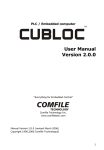
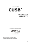
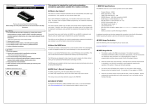
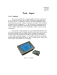
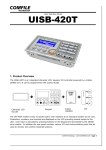
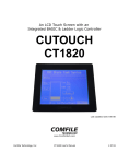
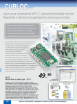
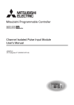
About
CUTOUCH is an integration of Touch panel, graphic LCD, and CUBLOC embedded
computer.
In the recent years, there has been increase of use of touch screens in
the industrial field.
But to use one, the user required connecting to a PLC and
learning to manipulate complex methods in order to use it.
In addition, cost of touch
screen has been very expensive.
Our CUTOUCH is a new type of embedded controller that integrates Touch screen,
PLC, and graphic LCD into one.
CUTOUCH
user’s manual
The biggest difference between CUTOUCH and other touch screens is that it’s the
only Visual Touch screen controller that can be programmed with BASIC and
LADDER in the world today.
BASIC language can be used to draw graphics and print characters to the LCD and
receive input from the touch screen before processing the x and y positions.
Sensor
input
RS232
through
I/O,
turning
relays
on/off,
AD/DA
conversion,
and
communication are very easy to implement in comparisons to traditional non-BASIC
***Warning!!!!!!!
Please be careful to not touch the inverter with label
DANGER.
PLCs.
With the LADDER LOGIC side of CUBLOC, the user may do sequential
processing and real-time logic processing as in traditional PLCs.
CUTOUCH has a flash memory for BASIC and LADDER programs.
can be used to download and debug.
A serial port
After downloading is done, it can run in a
“Stand-alone” state.
If you are thinking about developing a device that uses a touch screen, please review
CUTOUCH and we guarantee you that it will let you spend more time designing, and
less time to develop.
Comfile Technology Inc.
1
2
CuTOUCH
About CUTOUCH
* DANGER!!!!!!! Please be careful near the inverter, where a DANGER label is located,
large current flows through there!
CUTOUCH is an integration of CUBLOC core module, graphic LCD, and a touchpad.
The graphic LCD portion is GHLCD.
Front
You can use the CUBLOC’s GHLCD native
commands to draw, and print to the CUTOUCH.
GRA PHIC LCD MODULE
To implement a touch screen and PLC, it can add up to a big sum of money.
But
with CUTOUCH you do not need two different devices, you just need all-in-one device
Back
that will be less money in the long run.
TOUCH SCREEN + PLC
I/O PORT Connecter
CuTOUCH
DC 9~30V
3
4
RS232
Channel 1
Download
cable
I/O PORT
Menu System Library
CuTOUCH Dimensions
CuTOUCH supports extra commands for easy-to-use menus.
make for easy creation and manipulation of the menus.
These commands
With the menu system
library, a menu system shown in the below picture can be made in less than 10
minutes.
Comfile Automobile gas pressurizer
Select gas
Gas pressure
Gas left
Initialize
Auto type
Total cost
MENU Commands
CUTOUCH has memory space for about 100 MENU buttons.
Use MENUSET
command to set the x and y axis positions and the style of the MENU.
MENUTITLE command can be used to name the MENU.
Then
When touch input is
received, MENUCHECK command can be used to find the appropriate MENU.
0
CuTOUCH Mounting Instruction
CuTOUCH comes with mounting brackets.
99
Please install the mounting brackets as
shown below before installing CuTOUCH.
Each MENU button can be reset to another x and y axis positions and style by using
MENUSET command.
The only restriction is that up to 100 button can be inputted at
time, meaning usually in one screen.
another usage after each screen.
5
6
But you are free to reset each button to
Menucheck( )
Menuset
MENUSET
Variable = MENUCHECK( index, touchx, touchy)
index, style, x1, y1, x2, y2
Variable : Variable to store results (1 if selected, 0 if unselected)
Index : Menu Index Number
Index : Menu Index Number
Style : Button Style; 0=none, 1=Box, 2=Box with Shadow
Touchx : Touch pad x axis point
X1,y1,x2,y2 : Menu Button location
Touchy : Touch pad y axis point
Index value must be between 0~99.
Style is the shape of the button where 0 is no
box, 1 is for a box, and 2 is for a showed box.
Use this command Menucheck to see which menu is selected.
are the user’s touchpad input points.
If the Menu is selected, 1 is returned, otherwise 0 is returned.
0
1
If Menucheck(0,TX1,TY1) = 1 Then
2
Menureverse 0
Beep 18,180
x1,y1, x2, y2 are the x and y axis positions of the left upper and lower right corners.
End If
When this command is executed, the set part of the screen becomes part of the
button’s area.
Menureverse
Menutitle
MENUTITLE
MENUREVERSE index
index, x, y, string
Index : Menu index number
Index :Menu index number
X,y : Title location based on left upper corner of button
Selected menu box is inverted.
string : Name of the menu
Menuset only draws the box itself.
Use Menutitle command to set the name of the
Initialize
menu.
Menutitle 0,13,13,”Gas Left”
Menutitle 1,16,13,”Initialize”
Menutitle 2,13,13,”Total Cost”
Gas left
Initialize
Total cost
7
8
Total cost
Touchx and Touchy
Touch Pad Input Example
Waitdraw
You can use SETPAD, ON PAD, and GETPAD commands to find out which menus
WAITDRAW
were pressed from the user.
This command will wait for a drawing command to finish before resuming execution.
ELFILL
200,100,100,50
WAITDRAW
All PAD commands are geared for receiving and processing touch input.
‘ Fill an ellipse
We can use ON PAD interrupts to receive touch inputs.
‘ Wait until drawing is finished.
The following is an example
program that uses the touch pad:
This command is especially useful for animations and when you have trouble
'
displaying graphics because of the speed.
'
DEMO FOR CUTOUCH
'
CuTOUCH has an internal buffer for receiving graphic commands from CUBLOC.
this buffer fills up and data is sent to it, the data could get corrupted.
If
Const Device = CT1700
In order to
Dim TX1 As Word, TY1 As Word
avoid these situations, you can use the WAITDRAW command to wait until the buffer
Set Pad 0,4,5
‘Å (1) Activate Touch PAD Input
has enough space before sending graphic commands.
On Pad Gosub abc
‘Å (2) Declare pad interrupts
Do
Loop
If you need to draw graphics repeatedly, we recommend you use WAITDRAW to
abc:
avoid situations where the LCD might get blurry or received noise.
TX1 = Getpad(2)
‘Å (3) Interrupt Service routine
TY1 = Getpad(2)
This command can only be used with CuTOUCH.
Circlefill TX1,TY1,10
‘Å (4) Draw a circle where it
‘
was touched
Return
(1) SET PAD 0, 4, 5 : This command will activate the PAD inputs. (Syntax: SET PAD
mode, packet size, buffer size). CuTOUCH has a separate touch controller that will
sense touch input and send back to the CPU through SPI protocol.
controller” will create a signal that is equal to mode =
sampling)
This “touch
0. (MSB, RISING EDGE
Input packets are 4 bytes each ( X and Y each get 2 bytes).
Buffer size
is 5, 1 more than the actual packet size.
(2) ON Pad Gosub ABC: This command is for PAD interrupt declaration.
input occurs, it will jump to label ABC.
9
10
When PAD
Pulsout 18,300
(3) This is interrupt service routine.
until return will be executed.
When PAD input occurs, this is part of the code
End If
Getpad will read the data received from touch pad, 2
If Menucheck(2,TX1,TY1) = 1 Then
Menureverse 2
bytes for x position and 2 bytes for y position.
Pulsout 18,300
End If
(4) Draw a circle where touch input was received.
Return
When this program is executed, you will be able to see that wherever you press on
the screen, a circle will appear.
Please use this program as a skeleton for your
touch programs.
The following is MENU command and ON PAD command example:
When button is
pressed, a beep will sound from the piezo and the button will be inversed.
Start
End
Restart
'
'
DEMO FOR CuTOUCH
'
Const Device = CT1700
Dim TX1 As Integer, TY1 As Integer
Dim k As Long
Contrast 550
Set Pad 0,4,5
On Pad Gosub abc
Menuset 0,2,8,16,87,63
Menutitle 0,13,13,"Start"
Menuset 1,2,96,16,176,63
Menutitle 1,13,13,"End"
CuTOUCH I/O Ports
Menuset 2,2,184,16,264,63
The CT1720 model CuTOUCH has 82 I/O ports while the CT1700 has 18 I/O ports.
Menutitle 2,13,13,"Restart"
Low 18
Model Name
Input Only
Output Only
A/D Input
High Counter Input
Other I/Os
Total
Do
Loop
abc:
TX1 = Getpad(2)
TY1 = Getpad(2)
Circlefill TX1,TY1,10
If Menucheck(0,TX1,TY1) = 1 Then
Menureverse 0
Pulsout 18,300
‘ Send out beep to piezo
End If
If Menucheck(1,TX1,TY1) = 1 Then
Menureverse 1
11
12
CT1700
8
2
8
18
CT1720
32
32
8
2
8
82
CT1720
CT1700
With 82 I/O ports, the CT1720 has connectors as shown below.
GND 15 14 13 12 11 10 9
3
2
1
0
J2
J1
J12
13
J2
14
8
GND 7
J13
6
5
4
3
2
1
J12
J1
Vss
Vss
Vss
Vss
Vss
N/C
N/C
Vdd
Vdd
Vdd
D
T
CN 1
T0
J14
GND 15 14 13 12 11 10 9
Vss
Vss
Vss
Vss
Vss
N/C
N/C
Vdd
Vdd
Vdd
Block 1
J3
J4
CN
Block 0
Explanation
ADC0
ADC1
ADC2
ADC3
ADC4
ADC5
ADC6
ADC7
PWM0
PWM1
PWM2
PWM3
PWM4 / INT0
PWM5 / INT1
INT2
INT3
HIGH COUNT INPUT 0
HIGH COUNT INPUT 1
Internally connected to Piezo
(Can’t be accessed with Ladder)
GN
Port Block
Vss
Vdd
P7
P6
P5
P4
P3
P2
P2
P0
K14
4
Cnt1
Cnt0
P15
P14
P13
P12
P11
P10
P9
P8
K13
I/O
I/O
I/O
I/O
I/O
I/O
I/O
I/O
I/O
I/O
I/O
I/O
I/O
I/O
I/O
I/O
I/O
I/O
I/O
OUT
5
Vdd
Vdd
N/C
N/C
P39
P38
P37
P36
P35
P34
P33
P32
P31
P30
P29
P28
P27
P26
P25
P24
J12
Name
P0
P1
P2
P3
P4
P5
P6
P7
P8
P9
P10
P11
P12
P13
P14
P15
P16
P17
P18
6
Vss
Vss
N/C
N/C
P55
P54
P53
P52
P51
P50
P49
P48
P47
P46
P45
P44
P43
P42
P41
P40
Connectors
J13
GND 7
24V
24V
24V
N/C
P71
P70
P69
P68
P67
P66
P65
P64
P63
P62
P61
P60
P59
P58
P57
P56
J14
8
Vss
Vss
N/C
N/C
P87
P86
P85
P84
P83
P82
P81
P80
P79
P78
P77
P76
P75
P74
P73
P72
GN
D
CN
T
CN 1
T0
With 18 I/O ports, the CT1700 has connectors as shown below.
J4
J3
0
CuTOUCH add-on board.
Connector
Name
I/O
P0
P1
Port Block
Explanation
*If you input more than 5V into a CuTOUCH I/O port, it could cause the product to
I/O
ADC0
mal-function so please be careful.
I/O
ADC1
ADC2
Warning : CT1720 Output ports
ADC3
Please be aware of the following when using CT1720 with output ports (24 through
I/O
ADC4
55). When using CT1720 with a backup battery the data memory is saved during
I/O
ADC5
power OFF. Even the output on the I/O ports are saved to memory.
P6
I/O
ADC6
When powered ON, the output ports will recover from the status it was in at power
P7
I/O
ADC7
OFF.
P8
I/O
PWM0
This is to let the modules be able to continue their existing processes in case of
P9
I/O
PWM1
power outage.
P10
I/O
PWM2
Please be aware that when there are unknown values and battery backup is used,
PWM3
there can be garbage values at power ON, meaning unknown values outputting on
the output ports.
P2
I/O
J12
P3
I/O
(J3)
P4
P5
Block 0
J13
P11
I/O
(J3)
P12
I/O
PWM4 / INT0
P13
I/O
PWM5 / INT1
J14
Block 1
P14
I/O
INT2
Please use regular I/O ports if you need to make sure that the output needs to be
P15
I/O
INT3
OFF at power ON.
P16
I/O
HIGH COUNT INPUT 0
P17
IN
HIGH COUNT INPUT 1
P18
OUTPUT
Internally connected to Piezo BUZZER
(Cannot be accessed from Ladder)
P19~P2
N/C
3
J2
J4
P24~31
OUTPUT
Block 3
8 Output Ports
P32~39
OUTPUT
Block 4
8 Output Ports
P40~47
OUTPUT
Block 5
8 Output Ports
P48~55
OUTPUT
Block 6
8 Output Ports
P56~63
INPUT
Block 7
8 Input Ports
P64~71
INPUT
Block 8
8 Input Ports
P72~79
INPUT
Block 9
8 Input Ports
P80~87
INPUT
Block 10
8 Input Ports
N/C (No Connection ) means it’s not used..
CuTOUCH I/O ports are natively 5V friendly, to input 24V or use relay, please use our
15
16
There are extra RS232 connectors as shown below so you have the flexibility to be
Relays
able to access CuTOUCH when in an enclosed area.
Relays that can be used in CuTOUCH are shown below.
CuTOUCH has same
structure as the CB290.
Relay
Range
Units
Input/Output Relay P
P0~P127
1 bit
Feature
Internal Relay M
M0~M1023
1 bit
Internal status
Special Relay F
F0~F127
1 bit
System status
Timer Relay T
T0~T255
16 bit (1 Word)
Timers
Counter C
C0~C255
16 bit (1 Word)
Counters
Step-Enable S
S0~S15
256 Steps( 1 Byte)
Step-enable
Data D
D0~511
16
Data Storage
Interface
with
external
devices
bit
(1 Word)
P,M,F is in units of bits and T, C, and D are in units of Words.
To access P, M, and
F in units of Words, please use WP, WM, and WF, respectively.
RS232
Addtional
Connector
RS232
Channel 1
Download
cable
The Download RS232 Channel is a 4 pin type connector and RS232 Channel 1 is a 3
pin type connector as shown below.
Relay
Range
Units
WP
WP0~7
16 bit (1 Word)
Feature
P Access in units of Words
WM
WM0~WM63
16 bit (1 Word)
M Access in units of Words
WF
WF0~WF7
16 bit (1 Word)
F Access in units of Words
You can connect them to the PC SIDE RS232
WP0 is equal to P0 through P15 put together.
Pins as shown below:
P0 is placed in the LSB (Least
Significant Bit) and P15 is placed in the MSB (Most Significant Bit).
1
6
2
7
3
8
4
9
5
RD
GND
DTR
TD
RD
WMOV can be used to easily manipulate these relay areas.
Download / Monitoring
TD
DTR
GND
PC SIDE
GND
TD
RD
RS232 Channel 1
17
18
WP0
P15
P0
WP1
P31
P16
WP2
P47
P32
WP3
P63
P48
Commands like
KEEP Timer and KEEP Counter
Backup Battery
KEEP timer will retain its data values when powered off and restart from the data
CuTOUCH will maintain data in its data memory after power OFF by using its backup
values when power is turned on.
battery.
of CTU and CTD commands in order to make use of this KEEP timer and KEEP
If backup is not needed, the program must clear the memory at the
beginning of the program.
In BASIC, RAMCLEAR command can be used to clear all
counter.
data memory at the start of the program.
'
'
DEMO FOR CUTOUCH
'
Const Device = CT1700
Dim TX1 As Word, TY1 As Word
TX1 = 0
TY1 = 0
RAMCLEAR
‘ Clear just this variable
‘ Clear all RAM
For LADDER, all relays S, M, C, T, and D are backed up by the backup battery.
Relay P is cleared at power ON by default.
If you only want to clear parts of the
relay, not all relays, you can use the following method to clear:
Const Device = CT1700
Dim I As Integer
For I=0 to 32
‘ Clear only relay M0 to M32
_M(I) = 0
Next
Set Ladder On
Most traditional PLCs have KEEP memory for storing and restoring data in case of
power down.
CuTOUCH also has this feature by using a super capacitor, which
recharges itself and acts as a backup battery.
You also have the option of using
larger capacity capacitor or an actual battery.
19
20
KCTU and KCTD commands can be used in place
Please refer to KCTU, KCTD commands for detailed information.
MEMO
MEMO
21
22
CUTOUCH Sample Program
MEMO
SAMPLE 1
Let’s make a simple counter that will print to the screen.
are in your CUBLOC Studio installation directory.
The source files used here
(Usually C:\Program Files\Comfile
Tools\CublocStudio)
<Filename : CT001.CUL>
Const Device = Ct1700
Dim I As Integer
Contrast 550 ' LCD CONTRAST SETTING
Do
Locate 15,6
Print DEC5 I
Incr I
Delay 200
Loop
Please adjust your screen’s contrast accordingly using CONTRAST command.
* Depending on the model, you may be able to adjust the contrast using a adjustable
knob on the back of CuTOUCH.
manually.
23
24
In this case, you have the option to set the contrast
I = 0
SAMPLE 2
End If
The following example program will display RESET button and will increment number
Return
shown every time the button is pressed.
SET PAD command activates touch input.
label when touch input is received.
ON PAD command is used to jump to a
MENUSET command is used to set the desired
touch input area and MENUTITLE command is used to set the name of the button
itself.
PULSEOUT outputs BEEP sound to the piezo.
<Filename : CT002.CUL>
Const Device = Ct1700
Dim I As Integer
Dim TX1 As Integer, TY1 As Integer
Contrast 550
Set Pad 0,4,5
On Pad Gosub GETTOUCH
Menuset 0,2,120,155,195,200
Menutitle 0,20,14,"RESET"
Do
Locate 15,6
Print DEC5 I
Incr I
Delay 200
Loop
GETTOUCH:
TX1 = Getpad(2)
TY1 = Getpad(2)
If Menucheck(0,TX1,TY1) = 1 Then
Pulsout 18,300
25
26
SAMPLE 4
SAMPLE 3
Make a virtual keypad and accept numerical values.
Draw a circle where your finger touches.
1234
1
2
3
4
5
6
7
8
9
0
ENTER
<Filename : CT004.CUL>
<Filename : CT003.CUL>
Const Device = Ct1700
Const Device = Ct1700
Dim TX1 As Integer, TY1 As Integer
Dim TX1 As Integer, TY1 As Integer
Dim I As Integer
Contrast 550
Contrast 550
Set Pad 0,4,5
Set Pad 0,4,5
On Pad Gosub GETTOUCH
On Pad Gosub GETTOUCH
Do
Menuset 0,2,165,50,195,75
Loop
Menutitle 0,11,4,"1"
Menuset 1,2,205,50,235,75
GETTOUCH:
Menutitle 1,11,4,"2"
TX1 = Getpad(2)
Menuset 2,2,245,50,275,75
TY1 = Getpad(2)
Menutitle 2,11,4,"3"
Circlefill TX1,TY1,10
Menuset 3,2,165,85,195,110
Pulsout 18,300
Menutitle 3,11,4,"4"
Return
Menuset 4,2,205,85,235,110
Menutitle 4,11,4,"5"
Menuset 5,2,245,85,275,110
Menutitle 5,11,4,"6"
Menuset 6,2,165,120,195,145
Menutitle 6,11,4,"7"
Menuset 7,2,205,120,235,145
Menutitle 7,11,4,"8"
27
28
I = I + 7
Menuset 8,2,245,120,275,145
Pulsout 18,300
Menutitle 8,11,4,"9"
Elseif Menucheck(7,TX1,TY1) = 1 Then
Menuset 9,2,165,155,195,180
I = I << 4
Menutitle 9,11,4,"0"
I = I + 8
Menuset 10,2,205,155,275,180
Pulsout 18,300
Menutitle 10,17,4,"ENTER"
Elseif Menucheck(8,TX1,TY1) = 1 Then
I = I << 4
I =0
I = I + 9
Do
Pulsout 18,300
Loop
Elseif Menucheck(9,TX1,TY1) = 1 Then
I = I << 4
GETTOUCH:
Pulsout 18,300
TX1 = Getpad(2)
Elseif Menucheck(10,TX1,TY1) = 1 Then
TY1 = Getpad(2)
I = 0
If Menucheck(0,TX1,TY1) = 1 Then
Pulsout 18,300
I = I << 4
End If
I = I + 1
Locate 3,3
Pulsout 18,300
Print HEX4 I
Elseif Menucheck(1,TX1,TY1) = 1 Then
Return
I = I << 4
I = I + 2
The final value I is stored as BCD code, you can use BCD2BIN command to convert
Pulsout 18,300
back to a binary number.
Elseif Menucheck(2,TX1,TY1) = 1 Then
I = I << 4
I = I + 3
Pulsout 18,300
Elseif Menucheck(3,TX1,TY1) = 1 Then
I = I << 4
I = I + 4
Pulsout 18,300
Elseif Menucheck(4,TX1,TY1) = 1 Then
I = I << 4
I = I + 5
Pulsout 18,300
Elseif Menucheck(5,TX1,TY1) = 1 Then
I = I << 4
I = I + 6
Pulsout 18,300
Elseif Menucheck(6,TX1,TY1) = 1 Then
I = I << 4
29
30
SAMPLE 5
Let’s try using CuCANVAS to make some menus.
To create the virtual keypad
shown in the previous page, it would take a longer time to just code it.
We can save
ourselves time by using CuCANVAS.
Please run CuCANVAS and press Add Form button on the upper right hand corner.
Enter a desired name for your new form.
(Here we used NUMKEY)
You can make the rest of the buttons and the keypad like the one shown below can
be made in less than 5 minutes.
On the left side of CuCANVAS, you will see a tool bar with an arrow, box, filled box,
circle, filled circle, line, text, and menu box.
Please select the last button, menu box,
and draw a small box on the screen.
The 0 on the button means the menu number is 0.
will not be displayed.
In the actual screen, this number
Type “1” in the Title field on the top.
You have successfully
made a “1” button.
31
32
Click “Save to File” button and save as an include (*.inc) file.
Now is the fun part.
Code”.
Simply click on Generate on the menu bar and click “View Basic
CuCANVAS will generate a sub function that includes the button that you
have just created.
Simply copy(Ctrl+C) and paste(CTRL+V) to CUBLOC Studio and
wala! You have a menu in couple minutes.
For copying, you can either press Ctrl+C
or press on the “To Clipboard” button at the bottom.
Using the include file, you will be able to save lots of time and be able to make
changes to your menus without making it a big copy and paste hassle.
The following program is exactly same as SAMPLE4 except we use include file for
the virtual keypad.
<Filename : CT005.CUL>
Const Device = Ct1700
Dim TX1 As Integer, TY1 As Integer
Dim I As Integer
Contrast 550
Set Pad 0,4,5
On Pad Gosub GETTOUCH
‘ Execute the Sub-routine in INCLUDE file
NUMKEY
I =0
Do
Loop
You can also use include files instead of copying and pasting for repetitive menu
GETTOUCH:
creations.
TX1 = Getpad(2)
TY1 = Getpad(2)
If Menucheck(0,TX1,TY1) = 1 Then
I = I << 4
I = I + 1
Pulsout 18,300
Elseif Menucheck(1,TX1,TY1) = 1 Then
33
34
I = I << 4
Return
I = I + 2
Pulsout 18,300
End
Elseif Menucheck(2,TX1,TY1) = 1 Then
I = I << 4
#INCLUDE "CT005.INC"
I = I + 3
Pulsout 18,300
Elseif Menucheck(3,TX1,TY1) = 1 Then
We must include #include command at the end of the code.
I = I << 4
Slightly different from
other languages such as C++, but it works.
I = I + 4
Pulsout 18,300
You can see a call to the NUMKEY function at the beginning of the program, which
Elseif Menucheck(4,TX1,TY1) = 1 Then
calls the created source code to generate the virtual keypad.
I = I << 4
I = I + 5
Pulsout 18,300
Elseif Menucheck(5,TX1,TY1) = 1 Then
I = I << 4
I = I + 6
Pulsout 18,300
Elseif Menucheck(6,TX1,TY1) = 1 Then
I = I << 4
I = I + 7
Pulsout 18,300
Elseif Menucheck(7,TX1,TY1) = 1 Then
I = I << 4
I = I + 8
Pulsout 18,300
Elseif Menucheck(8,TX1,TY1) = 1 Then
I = I << 4
I = I + 9
Pulsout 18,300
Elseif Menucheck(9,TX1,TY1) = 1 Then
I = I << 4
Pulsout 18,300
Elseif Menucheck(10,TX1,TY1) = 1 Then
I = 0
Pulsout 18,300
End If
Locate 3,3
Print HEX4 I
35
36
Errata
Please refer to this errata file for bugs and fixes no shown in the manual.
Disclaimer of Liability: We will not be responsible for any damage occurring from
reader’s neglect of reading the errata file.
Please read the errata carefully in order to be aware of version changes.
Warning : CB290 / CT1720 Output ports
Please be aware of the following when using CB290 or CT1720 with output ports (24
through 55).
When using CB290 or CT1720 with a
backup battery (CB290 Proto-Board,
BaseBoard 64T, and CT1720), the data memory is saved during power OFF.
Even
the output on the I/O ports are saved to memory.
When powered ON, the output ports will recover from the status it was in at power
OFF.
This is to let the modules be able to continue their existing processes in case of
power outage.
Please be aware that when there are unknown values and battery backup is used,
there can be garbage values at power ON, meaning unknown values outputting on
the output ports.
Please use regular I/O ports if you need to make sure that the output needs to be
OFF at power ON.
37