1
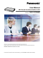
User Manual
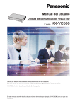
HD Visual Communication Unit
Model No.
KX-VC500
Thank you for purchasing a Panasonic HD Visual Communication Unit.
Please read this manual carefully before using this product and save this manual for future use.
KX-VC500: Software File Version 2.40 or later
In this manual, the suffix of each model number (e.g., KX-VC500XX) is omitted unless necessary.
Introduction
Introduction
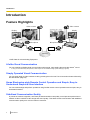
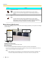
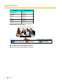
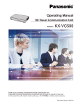
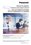
Feature Highlights
Video camera
Video camera
Display
Display
Microphone
Microphone
DCE *1
DCE *1
Router
Router
Internet
*1
DCE: Data Circuit-terminating Equipment
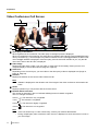
Lifelike Visual Communication
You can experience lifelike visual communication with smooth, high-quality video and clear stereo*1 sound.
*1
If using 2 or more Boundary Microphones, stereo output can be enabled through system settings (Page 89).
Simply Operated Visual Communication
You can easily begin a video conference call by pressing the unit’s One-Touch Connection button followed by
the Start button (Page 35).
Home Electronics-style Remote Control Operation and Simple, Easy to
Understand Graphical User Interface
You can make settings and perform operations using familiar remote control operations and a simple, easy to
understand interface.
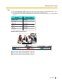
Stabilised Communication Quality
In periods of network congestion, automatic packet transmission rate quality control prevents packet loss to
maintain a video conference call’s image and sound quality. This allows visual communication with stabilised
communication quality even over an internet connection.
2
User Manual
Introduction
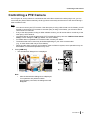
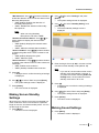
Remote Video Camera Operation via Remote Control
You can move the other party’s video camera up, down, left, and right as well as zoom in and out
(Page 55).
Selectable Video Source
By connecting your computer or video camera to the unit, you can show your computer’s screen or video
camera image to video conference call participants (Page 64, Page 68).
Encrypted Communication
Packets sent for video conference calls can be encrypted to prevent packet leaks, tampering, or
eavesdropping.
KX-VC Series NAT Traversal Service
"KX-VC Series NAT Traversal Service" is a service that allows you to easily and affordably set up and operate
a communication environment for the HD Visual Communication Unit.*1*2 Also, complicated router configuration
is unnecessary, which allows even people who are not network administrators set up a communication
environment. Furthermore, you can assign the unit a unique number (Terminal ID), which allows the unit to be
called not by IP address, but with the unique 7-digit number. This means communication can be initiated as if
calling a telephone. Communication can also be encrypted, so that you can communicate over the Internet
safely and securely.
For details about KX-VC Series NAT Traversal Service, refer to the following web site:
http://panasonic.net/psn/products/hdvc/nat_traversal/index.html
*1
*2
This service may be unavailable depending on the country/area of use. For details, contact your dealer.
This service may be unavailable depending on your router’s type or your Internet connection environment. For details, contact your
dealer.
Making Video Conference Calls via SIP Server
By using a SIP server, you can establish video conference calls not just by IP address, but also by specifying
a SIP URI (SIP user name@SIP domain name) instead. If the other party uses the same SIP domain name
as you, you can make a video conference call by specifying only the SIP user name (Page 99). For information
about supported SIP servers, contact your dealer.
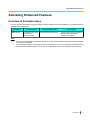
Enhanced Features through the Use of Activation Keys
By using an activation key (sold separately), you can enable connection to MCUs (multipoint control units) and
non-Panasonic video conference systems (Page 75). Features enabled through activation keys are available
even after performing a system initialisation (Page 101). For details about the activation key, contact your
dealer.
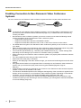
Connection to non-Panasonic Video Conference Systems
You can connect to a non-Panasonic video conference system and have a 2-party video conference call.*1 This
feature must be enabled with an activation key (Page 76, Page 101).
*1
For details about the types of non-Panasonic video conference systems you can connect to, contact your dealer. Communication
cannot be encrypted when you connect to a non-Panasonic video conference system. Instead, connect over an intranet or via a VPN
(Virtual Private Network).
User Manual
3
Introduction
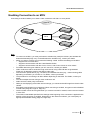
MCU Connection
By connecting to an MCU (multipoint control unit), you can make multiple-party video conference calls with 5
or more parties, rather than the normal maximum of 4 parties.*1 This feature must be enabled with an activation
key (Page 77, Page 101).
*1
4
For details about the types of MCUs you can connect to, contact your dealer. Communication cannot be encrypted when you connect
to an MCU. Instead, connect over an intranet or via a VPN (Virtual Private Network).
User Manual
Introduction
Trademarks
•
•
•
HDMI is a trademark or registered trademark of HDMI Licensing LLC in the United States and other
countries.
Polycom® is a trademark owned by Polycom, Inc. in the US and other countries.
All other trademarks identified herein are the property of their respective owners.
Licences
•
•
This product is licensed under the AVC Patent Portfolio License. This license permits the end user to
perform, for personal and non-commercial use, only the following actions:
– Encode video in compliance with the AVC Standard (below, "AVC Video").
– Decode AVC Video that was encoded by a consumer engaged in both personal and non-commercial
activity.
– Decode AVC Video obtained from a video provider licensed to provide AVC Video.
Additional information may be obtained from MPEG LA, LLC. See http://www.mpegla.com.
This product incorporates G.722.1 and G.722.1 Annex C licensed by Polycom®.
Open Source Software
Parts of this product use Open Source Software supplied based on the conditions of the Free Software
Foundation’s GPLs and/or LGPLs and other conditions. Relevant conditions apply to this software. Therefore,
please read license information about GPLs and LGPLs, and information about other Open Source Software
in the included CD-ROM before using this product. Also, some software parts of this product are licensed under
the MOZILLA PUBLIC LICENSE (MPL). At least three (3) years from delivery of products, Panasonic will give
to any third party who contacts us at the contact information provided below, for a charge of no more than the
cost of physically distributing source code, a complete machine-readable copy of the corresponding source
code and the copyright notices covered under GPL, LGPL, and MPL. Please note that software licensed under
GPL, LGPL, and MPL is not under warranty.
Contact Information
http://www.panasonic.net/corporate/global_network/
User Manual
5
Table of Contents
Table of Contents
For Your Safety ........................................................................................9
For Your Safety .................................................................................................................9
Before Operation ....................................................................................13
Notes about Operation ...................................................................................................13
Data Security ...................................................................................................................14
Privacy and Right of Publicity .......................................................................................14
Precaution ...............................................................................................15
Precaution ........................................................................................................................15
Preparation .............................................................................................17
Accessory Information ...................................................................................................17
Part Names and Usage ...................................................................................................18
Main Unit (Front) ............................................................................................................18
Main Unit (Back) .............................................................................................................19
Remote Control ..............................................................................................................20
Boundary Microphone (Optional Accessory) ..................................................................21
LED Patterns ..................................................................................................................22
Screen Standby ..............................................................................................................22
Connecting the Unit ........................................................................................................24
Turning the Power On/Off ..............................................................................................28
Screen Display ................................................................................................................29
Home Screen (Idle Screen) ............................................................................................29
Menu Screen (Idle Screen) ............................................................................................30
Video Conference Call Screen .......................................................................................32
Starting a Video Conference .................................................................34
Making a Video Conference Call ....................................................................................34
Calling Using Speed Dial (2-party Conference/3-party Conference/4-party
Conference) ....................................................................................................................34
Calling from the Contact List (2-party Conference/3-party Conference/4-party
Conference) ....................................................................................................................37
Calling by Entering an Address Directly .........................................................................39
Calling from the Call History ...........................................................................................42
Answering a Video Conference Call ..............................................................................45
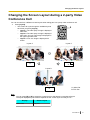
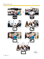
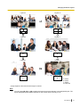
Changing the Screen Layout ................................................................47
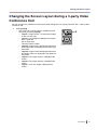
Changing the Screen Layout during a 2-party Video Conference Call ......................47
Changing the Screen Layout during a 3-party Video Conference Call ......................49
Changing the Screen Layout during a 4-party Video Conference Call ......................52
Controlling a PTZ Camera .....................................................................55
Controlling a PTZ Camera ..............................................................................................55
Recalling a Registered Preset ........................................................................................58
Adjusting the Volume and Tone ...........................................................60
Adjusting the Volume .....................................................................................................60
Muting the Microphone ...................................................................................................61
Reducing Microphone Noise ..........................................................................................62
Adjusting the Tone ..........................................................................................................63
6
User Manual
Table of Contents
Displaying Other Video Sources ..........................................................64
Displaying a Computer’s Screen ...................................................................................64
Displaying the Sub Video Camera’s Image ..................................................................68
Displaying the Connection Status ........................................................72
Displaying the Connection Status .................................................................................72
Displaying Unit Information ...........................................................................................73
About Enhanced Features .....................................................................75
Activating Enhanced Features .......................................................................................75
Overview of Activation Keys ...........................................................................................75
Enabling Connection to Non-Panasonic Video Conference Systems ............................76
Enabling Connection to an MCU ....................................................................................77
Contacts and Settings ...........................................................................79
Adding Contacts to the Contact List .............................................................................79
Registering a New Contact .............................................................................................79
Editing Contact Information ............................................................................................80
Deleting a Contact ..........................................................................................................81
Registering a Contact from the Call History ...................................................................81
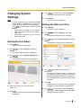
Changing System Settings .............................................................................................83
Setting the Unit Name ....................................................................................................83
Setting the Date and Time ..............................................................................................83
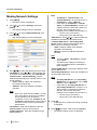
Making Network Settings ................................................................................................84
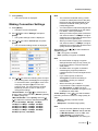
Making Connection Settings ...........................................................................................85
Making Screen Standby Settings ...................................................................................87
Making Sound Settings ..................................................................................................87
Setting the MIC Position .................................................................................................88
Making Remote Control Settings ....................................................................................91
Making Language Settings .............................................................................................92
Making Multicast Setting ................................................................................................93
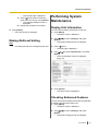
Performing System Maintenance ..................................................................................93
Display Unit Information .................................................................................................93
Checking Enhanced Features ........................................................................................93
Performing a Network Test .............................................................................................94
Performing Self Diagnosis ..............................................................................................94
Performing Remote Maintenance ...................................................................................95
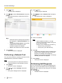
Making Administrator Menu Settings ............................................................................96
Logging in to the Administrator Menu .............................................................................96
Making Administrator Password Settings .......................................................................96
Making Encryption Settings ............................................................................................97
Making Software Update Settings ..................................................................................98
Making Connection Mode Setting ..................................................................................99
Making SIP Settings .......................................................................................................99
Performing System Initialisation ...................................................................................101
Activating Enhanced Features .....................................................................................101
Updating Software ........................................................................................................102
Making Audio Input Settings .........................................................................................103
Making HDMI Settings (for Checking Operation) .........................................................104
Making Local Site Settings ...........................................................................................105
Registering a Local Site ...............................................................................................105
Selecting a Local Site ...................................................................................................107
Editing Local Site Information .......................................................................................108
Deleting Local Site Information ....................................................................................108
User Manual
7
Table of Contents
Input ......................................................................................................110
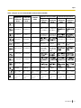
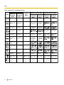
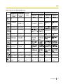
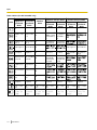
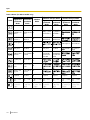
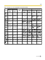
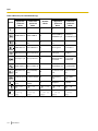
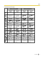
Inputting Letters and Numbers ....................................................................................110
Miscellaneous .......................................................................................121
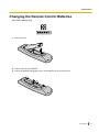
Changing the Remote Control Batteries .....................................................................121
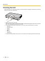
Cleaning the Unit ...........................................................................................................122
Additional Information .........................................................................123
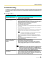
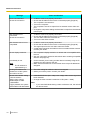
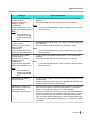
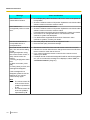
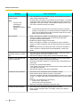
Troubleshooting ............................................................................................................123
Basic Operation ............................................................................................................123
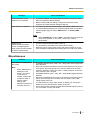
Audio ............................................................................................................................129
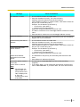
System Settings ...........................................................................................................130
If These Messages Appear ..........................................................................................131
Miscellaneous ...............................................................................................................137
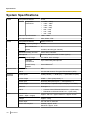
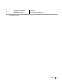
Specifications .......................................................................................138
System Specifications ..................................................................................................138
Index............................................................................................................140
8
User Manual
For Your Safety
For Your Safety
For Your Safety
To prevent personal injury and/or damage to property,
be sure to observe the following safety precautions.
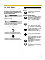
The following symbols classify and describe the
level of hazard and injury caused when this unit is
operated or handled improperly.
WARNING
Denotes a potential hazard that could result in
serious injury or death.
CAUTION
Denotes a hazard that could result in minor injury or
damage to the unit or other equipment.
The following types of symbols are used to classify
and describe the type of instructions to be
observed. (The following symbols are examples.)
This symbol is used to alert users to a specific
operating procedure that must not be performed.
This symbol is used to alert users to a specific
operating procedure that must be followed in order
to operate the unit safely.
WARNING
General
Follow all warnings and instructions
marked on the unit.
Power and Earth Connection
The power source voltage of this unit is
listed on the nameplate. Only plug the
unit into an AC outlet with the proper
voltage. If you use a cord with an
unspecified current rating, the unit or
plug may emit smoke or become hot to
the touch.
Do not connect the unit to the AC outlet,
AC extension cords, etc., in a way that
exceeds the power rating of, or does not
comply with the instructions provided
with, the AC outlet, AC extension cords,
etc.
To ensure safe operation the power cord
supplied must be inserted into a
standard three-prong AC outlet which is
effectively earthed through the normal
wiring.
The fact that the equipment operates
satisfactorily does not imply that the
power point is earthed and that the
installation is completely safe. For your
safety, if in any doubt about the effective
earthing of the power point, consult a
qualified electrician.
Plug the power cord firmly into an AC
outlet. Otherwise, it can cause fire or
electric shock.
Do not pull, bend, rest objects on, or
chafe the power cord and plug. Damage
to the power cord or plug can cause fire
or electric shock.
User Manual
9
For Your Safety
To prevent fires, electric shock, injury, or
damage to the unit, be sure to follow
these guidelines when performing any
wiring or cabling:
a. Before performing any wiring or
cabling, unplug the unit’s power cord
from the outlet. After completing all
wiring and cabling, plug the power
cord back into the outlet.
b. Do not place any objects on top of
the cables connected to the unit.
c. When running cables along the floor,
use protectors to prevent the cables
from being stepped on.
d. Do not run any cables under
carpeting.
Do not attempt to repair the power cord,
or plug. If the power cord or plug is
damaged or frayed, contact an
authorised service representative for a
replacement.
Ensure that the plug connection is free
of dust. In a damp environment, a
contaminated connector can draw a
significant amount of current that can
generate heat, and eventually cause fire
if left unattended over an extended
period of time.
Stop operation immediately if the unit
emits smoke, excessive heat, abnormal
smell or unusual noise. These conditions
can cause fire or electric shock.
Immediately turn the unit off, and unplug
the power cord, and contact your dealer
for service.
Do not connect or disconnect the AC
plug with wet hands. Danger of electric
shock exists.
When disconnecting the unit, grasp the
plug instead of the cord. Pulling on a
cord forcibly can damage it, and cause
fire or electric shock.
During thunderstorms, do not touch the
unit and plug. It may cause an electric
shock.
10
User Manual
Operating Safeguards
Do not disassemble this unit. Only
qualified personnel should service this
unit. Disassembling the unit may expose
you to dangerous voltages or other risks.
Incorrect reassembly can cause electric
shock.
Do not alter the unit or modify any parts.
Alteration or modification can cause fire
or electric shock.
If metal fragments or water gets into the
unit, turn the unit off and unplug the unit
immediately. Contact your dealer for
service. Operating the contaminated unit
can cause fire or electric shock.
Do not insert objects of any kind into this
unit, as they may touch dangerous
voltage points or short out parts that
could result in a fire or electric shock.
Do not use a unit in the vicinity of a gas
leak to report the leak.
Do not place the remote control in
microwave ovens or on induction
cookware.
Clean the AC plug periodically with a
soft, dry cloth to remove dust and other
debris.
Do not use the supplied power cord with
any other device. It may cause fire or
electric shock.
Never open or remove unit covers that
are screwed with screws. A high-voltage
component can cause electric shock.
For Your Safety
Unplug the unit from the AC outlet and
have it serviced by qualified service
personnel in the following cases:
a. If the unit does not operate
according to the operating
instructions. Adjust only the controls
that are explained in the operating
instructions. Improper adjustment of
other controls may result in damage
and may require service by a
qualified technician to restore the
unit to normal operation.
b. If the unit has been dropped or the
cabinet has been damaged.
c. If unit performance deteriorates.
If damage to the unit exposes any
internal parts, disconnect the power cord
immediately and return the unit to your
dealer.
Installation
Do not install the unit in any other way
than described in relevant manuals.
Do not touch the unit, AC adaptor, AC
adaptor cord, or AC cord during a
lightning storm.
The AC adaptor should be connected to
a vertically oriented or floor-mounted AC
outlet. Do not connect the AC adaptor to
a ceiling-mounted AC outlet, as the
weight of the adaptor may cause it to
become disconnected.
Only connect the unit to the type of
electric power specified on the label
affixed to the unit. Confirm the type of
electric power supplied to the installation
site if necessary.
Battery
The battery contains diluted sulfuric
acid, a very toxic substance. If the
battery leaks and the liquid inside spills
on the skin or clothing, immediately
wash it off with plenty of clean water. If
the liquid splashes into eyes,
immediately flush the eyes with plenty of
clean water and consult a doctor.
Sulfuric acid in the eyes may cause loss
of eyesight and acid on the skin will
cause burns.
Do not charge, short, heat, break or
throw in a fire, as it may result in the
battery leaking, generating heat, or
bursting.
Do not connect the positive terminal and
the negative terminal of the battery to
each other with any metal object (such
as wire).
Do not carry or store the batteries
together with necklaces, hairpins, or
other metal objects.
Do not mix old and new batteries or
different types of batteries.
Batteries that seem worn down or
damaged should not be used. Using
worn down or damaged batteries may
result in leaking.
Do not use rechargeable batteries.
Take the depleted batteries out of the
remote control. Otherwise, the batteries
may leak.
User Manual
11
For Your Safety
CAUTION
Power
When the unit is not used over an
extended period of time, take the
batteries out of the remote control.
Otherwise, the batteries may leak. Do
not use the leaked batteries.
When the unit is not used over an
extended period of time, switch it off and
unplug it. If an unused unit is left
connected to a power source for a long
period, degraded insulation may cause
electric shock, current leakage, or fire.
The unit should be used only with the
power cord enclosed with the unit.
Installation
The unit should be kept free of dust,
moisture, high temperature (more than
40 °C) and vibration, and should not be
exposed to direct sunlight.
Place this unit on a flat surface. Serious
damage and/or injury may result if the
unit falls.
Allow 10 cm clearance around the unit
for proper ventilation.
Do not place the unit in an area close to
fire. Doing so may cause fire.
Battery
Be sure to use the specified type of
batteries only.
Ensure that batteries are installed with
correct polarity. Incorrectly installed
batteries can burst or leak, resulting in
spillage or injuries.
12
User Manual
This product contains batteries. Replace
only with the same or equivalent type.
Improper use or replacement may cause
overheating, rupture or explosion
resulting in injury or fire. Dispose of used
batteries according to the instructions of
your local solid waste officials and local
regulations.
When replace the batteries for the
remote control, use R6 (AA) type dry
cell.
Do not install the battery backwards so
that the polarity is reversed.
Before Operation
Before Operation
Notes about Operation
Please pay attention to the following points when using
this device:
1. Please contact your dealer for installing,
upgrading, or repairing this device.
10. Avoid placing the device in areas with high
humidity, and exposing it to rain.
Neither the main unit nor the power plug is water
resistant.
11. The power outlet should be near the product
and easily accessible.
2. Do not forcefully hit or shake this device.
Dropping or bumping this device can damage or
break this device.
3. Do not place this device in a freezer or other
location where it is exposed to cold
temperatures.
Doing so may result in damage or malfunctions.
4. Place this device at least 2 m away from radios,
office equipment, microwave ovens, air
conditioning units, etc.
Noise from electronic devices can cause static and
interference in other devices.
5. Do not place this device in a location where it is
exposed to hydrogen sulfide, phosphorous,
ammonia, sulfur, carbon, acid, dirt, toxic gas,
etc.
Doing so may result in damage, and the usable
life-span of the device may decrease.
6. Do not apply insecticides or other volatile
liquids to the device, nor leave rubber bands or
vinyl objects on the device for extended periods
of time.
Doing so may result in alterations to the material or
paint peeling off the device.
About the Operating Environment
This device includes a feature that automatically adjusts
voice transmissions to improve clarity. After beginning
a video conference call, adjustments to the call
environment may not complete immediately, and as a
result voices may cut out or echo. In such cases, at the
beginning of the video conference call, be sure to speak
in turn with other parties.
About Moving the Device
Do not move this device while cords are still connected.
Doing so may result in damage to the cords.
Other
•
•
The unit may not operate in the event of a power
failure.
The illustrations and screenshots in this manual are
for reference only and may vary from the actual
product.
7. Do not bring cards with magnetic strips, such
as credit cards and telephone cards, near the
microphone.
Cards might become unusable.
8. Do not bring the device near items that emit
electromagnetic waves or that are magnetised
(high-frequency sewing machines, electric
welders, magnets, etc.).
Doing so may result in static noise or damage.
9. Keep the device at least 10 cm away from all
walls.
If placed against a wall, the device may not be able
to ventilate properly, which may lead to a system
malfunction due to overheating.
User Manual
13
Before Operation
Data Security
We recommend observing the security precautions
described in this section, in order to prevent the
disclosure of sensitive information.
Panasonic is not responsible for any damages
caused by improper use of this device.
Preventing Data Loss
Privacy and Right of
Publicity
By installing and using this device, you are responsible
for maintaining the privacy and usage rights of images
and other data (including sound picked up by the
microphone). Use this device accordingly.
•
Keep a separate record of the encryption key and all
information stored in the contact list.
Preventing Data Disclosure
•
Do not place this device in a location that can be
accessed or removed without authorisation.
• If important information is saved on this device,
store it in an appropriate location.
• Do not store sensitive personal information in the
unit.
• In the following situations, make a record of the
encryption key and the information stored in the
contact list and return the unit to the state it was in
when purchased (Page 101).
– Before lending or disposing of the unit
– Before handing the unit over to a third party
– Before having the unit serviced
• Make sure the unit is serviced by only a certified
technician.
This device can register and store personal data (the
contact list, encryption key, connection history, etc.). In
order to prevent the disclosure of data stored on this
device, make sure to delete all data that is registered
and stored on this device prior to disposing of, lending,
or returning this device (Page 101).
Preventing Data Disclosure over the
Network
•
•
•
•
14
To ensure the security of private conversations,
only connect the unit to a secure network.
To prevent unauthorised access, only connect the
unit to a network that is properly managed.
Make sure all computers connected to the unit
employ up-to-date security measures.
To prevent illegal access from the Internet, activate
a Firewall.
User Manual
•
Privacy is generally said to be, "A legal guarantee
and right not to have the details of one’s personal
life unreasonably publicised, and the right to be able
to control information about oneself. In addition,
right of publicity is a right not to have a likeness of
one’s face or figure photographed and publicised
without consent".
When the Automatic Answer feature is enabled,
transmission begins as soon as a video conference
call is received. The receiver of the video
conference call will begin transmitting as soon as
the video conference call is received at any time,
from any caller. Please be aware when the
Automatic Answer feature is enabled, there is a risk
that due to an unexpected, automatically answered
video conference call, privacy rights may be
violated or sensitive information may be transmitted
to unauthorised parties.
Precaution
Precaution
Precaution
These symbols on the products, packaging,
and/or accompanying documents mean that
used electrical and electronic products and
batteries should not be mixed with general
household waste.
For proper treatment, recovery and
recycling of old products and used batteries,
please take them to applicable collection
points, in accordance with your national
legislation and the Directives 2002/96/EC
and 2006/66/EC.
By disposing of these products and batteries
correctly, you will help to save valuable
resources and prevent any potential
negative effects on human health and the
environment which could otherwise arise
from inappropriate waste handling.
For more information about collection and
recycling of old products and batteries,
please contact your local municipality, your
waste disposal service or the point of sale
where you purchased the items.
Penalties may be applicable for incorrect
disposal of this waste, in accordance with
national legislation.
For users in the United Kingdom
FOR YOUR SAFETY, PLEASE READ THE
FOLLOWING TEXT CAREFULLY.
This appliance is supplied with a moulded three-pin
mains plug for your safety and convenience. Should the
fuse need to be replaced, please ensure that the
replacement fuse is of the same rating and that it is
approved by ASTA or BSI to BS1362.
Check for the ASTA mark
or the BSI mark
on
the body of the fuse.
If the plug contains a removable fuse cover, you must
ensure that it is refitted when the fuse is replaced. If you
lose the fuse cover, the plug must not be used until a
replacement cover is obtained. A replacement fuse
cover can be purchased from your local Panasonic
dealer.
IF THE FITTED MOULDED PLUG IS UNSUITABLE
FOR THE AC OUTLET IN YOUR PREMISES, THEN
THE FUSE SHOULD BE REMOVED AND THE PLUG
CUT OFF AND DISPOSED OF SAFELY. THERE IS A
DANGER OF SEVERE ELECTRICAL SHOCK IF THE
CUT-OFF PLUG IS INSERTED INTO ANY 13 AMP
SOCKET.
For business users in the European
Union
If you wish to discard electrical and
electronic equipment, please contact your
dealer or supplier for further information.
WARNING
Information on disposal in other
countries outside the European Union
These symbols are only valid in the
European Union. If you wish to discard these
items, please contact your local authorities
or dealer and ask for the correct method of
disposal.
This appliance must be earthed.
How to replace the fuse: Open the fuse compartment
with a screwdriver and replace the fuse and fuse cover.
Note for the battery symbol (bottom two
symbol examples):
This symbol might be used in combination
with a chemical symbol. In this case it
complies with the requirement set by the
Directive for the chemical involved.
For users in the European Union only
Information for Users on Collection and Disposal of
Old Equipment and used Batteries
For users in Germany only
• Machine Noise Information Ordinance, 3rd
•
GPSGV: The highest sound pressure level is 70 dB
(A) or less according to EN ISO 7779.
This equipment is not for use at video display work
stations according to BildscharbV.
User Manual
15
Precaution
For users outside the European Union
WARNING
•
This is a class A product. In a domestic
environment this product may cause radio
interference in which case the user may be
required to take adequate measures.
For users in Taiwan only
Notice
•
16
This product contains a CR coin lithium battery.
When disposing of the product, the battery must
be removed. Contact your dealer for details.
User Manual
Preparation
Preparation
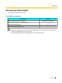
Accessory Information
The following accessories are included:
Included Accessories
Accessories
Power cord (earth terminal included)
Quantity
Depends on country/area
Remote control (Part No.: N2QAYB000674)
1
Batteries (R6 [AA] dry cell)
2
CD-ROM (included manuals, etc.)
1
Note
•
•
The number and type of power cords may vary depending on the country/area of use. Please use
whichever is appropriate for the country/area.
Product documentation may vary depending on the country/area of use.
User Manual
17
Preparation
Part Names and Usage
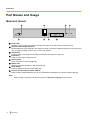
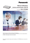
Main Unit (Front)
A
E
B
F
C
G
D
H
Power LED
Shows the power status. The LED is red when the power is on and off when the power is off.
Remote Control Signal Receiver
Receives Remote Control signals. The maximum range of reception is approximately 8 m from front of the
unit, and approximately 3 m from 20° on each side, total 40°.
Start button
Press to make or manually answer video conference calls (Page 34, Page 45).
End button
Press to end a video conference call.
Power button
Turns the power on and off (Page 28).
Status LED
Shows the operational status of the unit (Page 22).
Home button
Press to display the Home screen (Page 29).
One-Touch Connection buttons (LED lit)
Press to select a dial destination from up to 5 destinations displayed on the Home screen (Page 35).
Note
•
18
During a video conference call, buttons other than [Power] and [End] cannot be used.
User Manual
Preparation
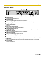
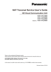
Main Unit (Back)
RS-232C terminal
This terminal is not available for use.
MIC jack (Page 24)
Used to connect the Boundary Microphone (optional) (Page 21).
Audio In L/R jack (Page 24)
Used to connect general-purpose microphones (not for the Boundary Microphone).
LAN jack (Page 24)
Connect a LAN cable.
Camera Control terminal
Not used.
Main Camera terminal (Page 24)
Connect the main video camera with an HDMI cable.
Sub Camera terminal (Page 68)
Used to connect a second, sub video camera with an HDMI cable for sharing video contents apart from
the main video camera.
RGB terminal (Page 64)
Used to connect a computer for sending screens to participants.
HDMI terminal (Page 24)
Used to connect to the display with an HDMI cable.
Component terminal (Page 27)
Used to connect to the display with a component video cable.
Audio Out L/R jack
Used to connect an amplifier or active speaker (Page 26). Also used to connect the speakers of a display
without an HDMI terminal for audio output (Page 27).
GND terminal
Used to connect an earthing wire when the power cord’s earth terminal connection is not available.
AC IN (Page 24)
Connect the power cord.
User Manual
19
Preparation
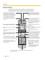
Remote Control
Press to show the sub video camera’s images on your and the other party’s
display during a video conference call. When not on a video conference call,
the sub video camera’s images are shown on your display only (Page 69).
Press to show your computer’s
screen on your and the other party’s
display during a video conference
call. When not on a video conference
call, the computer screen is shown
on your display only (Page 65).
Press to display/hide information
about the other party, guide area
and duration, during a call (Page
33).
Press to enter screen standby mode
(Page 22).
Press to change the layout of the
screen during a call (Page 47).
Press to return to the main video
camera after showing images from a
computer or sub video camera
(Page 66, 70).
Press to make or manually answer
video conference calls (Page 35, 45).
Press to display the Menu screen
(Page 30).
Press to end a call.
Press to move the cursor and select
items.
Press to confirm the selected item or
entered information.
Press to display the Home screen
(Page 29).
Press to return to the previous
screen.
Press to select the feature assigned
to each colour. Available features are
displayed in the guide area (Page
29).
Press to adjust the volume during a
call. Press [+] to increase and [–] to
decrease the volume (Page 60).
Press to select a tone (equalizer)
setting during a call (Page 63).
Press to operate the other party’s
PTZ (Pan, Tilt, Zoom) camera when
on a video conference call (Page 55).
Press to mute the microphone
during a call, so that the other party
cannot hear your voice (Page 61).
Press to display the connection
status of the network and peripheral
devices (Page72).
Press to display your contact list.
This can be pressed while the
following screens are displayed:
• Home screen
• Menu screen
• Computer’s screen/sub video
camera’s image (when not on a
video conference call)
Press to dial or perform settings where inputting digits/characters is
required (Page 110).
20
User Manual
Preparation
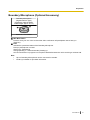
Boundary Microphone (Optional Accessory)
Boundary Microphone
(Digital Interface Type)
(Proprietary cable included.
Cable length: approx. 8.5 m)
A
B
Model No.: KX-VCA001
MIC Mute button
Press to mute your own voice so that other video conference call participants cannot hear you
(Page 61).
LED
Indicate the operational status of the Boundary Microphone.
Red (on): Microphone is muted.
Green (on): Transmitting
Orange (blinking in 1 second intervals): Starting up
Off: No transmission in progress or microphone disabled because the unit is receiving a multicast call.
Note
•
•
Up to 4 Boundary Microphones can be connected in cascade.
Contact your dealer for purchase information.
User Manual
21
Preparation
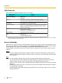
LED Patterns
LEDs indicate the operational status of the unit, as follows:
LED pattern
*1
Status
Slow blue flashing
•
•
Starting up
Idle state
Blue on
•
In a video conference call (including when dialling,
receiving a video conference call, and being disconnected)
Orange on
•
Self diagnosis is being performed.
Orange flashing
•
Mismatch of field frequency*1 between the unit and display.
(After 30 seconds the flashing will stop and the unit will
restart in safe mode.)
Red on
•
•
An error has occurred.
Maintenance is being performed.
Red flashing
•
A serious error has occurred.
Off
•
•
Power is off.
In screen standby mode
Devices such as the display or video camera operate with a particular field frequency, depending on their video format. For details
on the field frequency, contact your dealer.
Screen Standby
When there is no video conference call transmission, and the unit or remote control is not operated for more
than 10 minutes (default), or when the remote control’s [Video Out On/Off] button is pressed, the unit enters
screen standby mode. Video out to the display is suspended and the status LED turns off.
Screen standby mode ends when the unit or remote control is operated, or when a video conference call is
received.
Notice
•
If screen standby mode ends and no image is visible, check to see if the display or video camera’s
power saving settings are enabled. Check each device’s manual for more information about its power
saving settings.
Note
•
•
•
•
•
22
You can change the length of time until the unit enters screen standby mode (Page 87).
The unit will not enter screen standby mode while displaying a computer’s screen or a sub video
camera’s image, even if the unit or remote control is not operated for a period of time.
When the unit or remote control is operated and screen standby mode ends, the Home screen will be
displayed.
If a button is pressed on the unit or remote control to end screen standby mode, that button’s operation
is not performed in that case.
If screen standby mode begins while editing information in the contact list or other screen, any unsaved
changes will be lost.
User Manual
Preparation
•
It takes about 7 seconds to return from screen standby mode. (The length of time may vary depending
on the type of display you are using.)
User Manual
23
Preparation
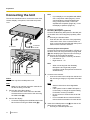
Connecting the Unit
Note
•
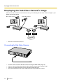
This section describes how to connect the main video
camera, display, microphone, LAN cable and power
cord.
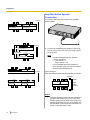
If your display is not compatible with HDMI,
use a component cable (Page 27). Since
sound signals are not transmitted when
using a component cable, connect an
amplifier/active speaker (Page 26), or use
the display’s speakers (Page 27).
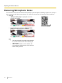
3. Connect a microphone.
E
F
To earthed
AC outlet
To a router
C
A
B
To a display
Notice
•
Use only the included power cord.
•
When connecting both the Boundary
Microphone and a general-purpose
microphone, both microphones can be used
simultaneously.
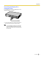
4. Connect to the network.
• Connect a router to the LAN jack on the back of
the unit using a category 5 or greater LAN cable
(E).
Note
Note
•
General-purpose microphone
Connect the microphone to the Audio In L/R jack on
the back of the unit using the stereo pin plug cable
(D) after amplifying the signal to line level using a
device such as a microphone amplifier.
• Connect the microphone correctly, as follows:
– Left channel ® L
– Right channel ® R
Note
D
To each device
Boundary Microphone (optional)
Connect the Boundary Microphone to the MIC jack
on the back of the unit using the proprietary cable
(C).
• Use only the included cable.
• Push and turn the connector of the proprietary
cable until it clicks. If the connector does not
click, try reconnecting the cable with the top and
bottom of the connector reversed.
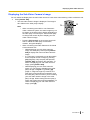
Make sure to read the instruction manuals for
all devices being connected.
1. Connect the main video camera.
• Connect the main video camera to the Main
Camera terminal on the back of the unit using
an HDMI cable (A).
2. Connect the display.
• Connect the display to the HDMI terminal on the
back of the unit using an HDMI cable (B).
•
•
•
•
Set the hub/router to Auto Negotiation
mode.
If the system is set to 100M Full Duplex, it
is necessary to change the system setting.
For details, contact your dealer.
Do not connect to a hub/router set to Half
Duplex.
For more details about routers and DCEs,
refer to the documentation for each device.
5. Insert the included power cord (F) into the AC IN
terminal on the back of the unit.
• Use only the included power cord.
24
User Manual
Preparation
Note
6. Plug in the power cord into the power outlet.
• Choose an outlet that is convenient for
•
Make sure that the Boundary Microphones are
placed at least 1 m away from the display and
speakers.
Do not connect more than 4 Boundary
Microphones. Doing so will cause all Boundary
Microphones to stop working.
When 2 or more Boundary Microphones are
connected, if you want to change the output
sent to the other party to stereo, it is necessary
to configure the settings manually (Page 89).
If you are connected to an MCU or
non-Panasonic video conference system, the
output sent to the other party will be monaural.
plugging/unplugging.
•
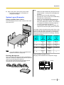
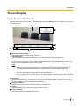
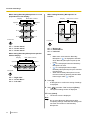
System Layout Examples
Display and Main Video Camera
•
Place the display and main video camera at the same
side of the room.
•
The range of each microphone (the radius of the circle
with a microphone at the centre) varies according to the
level of surrounding and the number of microphones
being used. Place microphones accordingly, referring
to the following table.
Note
•
If you use speakers, refer to "Amplifier/Active
Speaker Connection" (Page 26).
Boundary Microphones
Noise
level/
Micro–
phone
A quiet
room
(40
dBsplA)
A regular
room
(45
dBsplA)
A noisy
room
(50
dBsplA)
1
approx.
3m
approx.
2.2 m
approx.
1.2 m
2
approx.
2.8 m
approx.
1.5 m
approx.
1m
3
approx.
2.3 m
approx.
1.3 m
—
4
approx.
2m
approx.
1.1 m
—
Layout examples (a regular room)
(the grey circle indicates the microphone’s range):
Up to 4 Boundary Microphones can be connected in
cascade. There are no separate terminals for input and
output on the Boundary Microphones.
Also, Boundary Microphones and general-purpose
microphones can be used simultaneously.
Display
4m
Microphone
User Manual
25
Preparation
Amplifier/Active Speaker
Connection
Display
This section describes how to connect an amplifier/
active speaker.
4m
4m
Microphone
Microphone
4m
4m
Display
Microphone
1. Connect the amplifier/active speaker to the Audio
Out L/R jack on the back of the unit using a stereo
pin plug cable.
Microphone
4m
Note
Microphone
•
•
4m
Microphone
4m
Display
Microphone
Connect the amplifier/active speaker
correctly, as follows:
– Left channel ® L
– Right channel ® R
For more details about the amplifier or
active speaker, refer to the documentation
for the corresponding device.
Layout example:
Place the speakers either side of the display, as follows:
Speaker
4m
Microphone
Display
4m
Main
video
camera
Microphone
Microphone
Speaker
Notice
•
26
User Manual
Place the speakers either side of the display. If
you place the display at the front of the room
and the speakers at the back, the microphone’s
left/right spatial direction may be reversed, and
the orientation of the image and sound will not
match on the other party’s side.
Preparation
Connecting the Display with a
Component Cable
If your display does not have an HDMI terminal, use a
component cable for connection.
1. Connect the display to the Component terminal on
the back of the unit using a component cable.
Note
•
To use the display’s speakers to output audio,
connect the display to the Audio Out L/R jack
(Page 19) on the back of the unit using a stereo
pin plug cable.
User Manual
27
Preparation
Turning the Power On/Off
Note
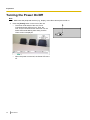
•
1
Make sure that peripheral devices (e.g., display, main video camera) are turned on.
Press the [Power] button on the front of the unit.
• The Power LED and all of the One-Touch
Connection button LEDs turn on. Then, the
One-Touch Connection button LEDs turn off, the
Status LED starts flashing blue slowly, and the
Home screen is displayed.
•
28
When the power is turned off, the Power LED turns
off.
User Manual
1
Preparation
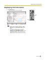
Screen Display
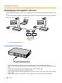
Home Screen (Idle Screen)
Displayed when the power is turned on. Also displayed when the [Home] button is pressed on the unit or on
the remote control.
A
B
C
F
D
E
Main Video Camera Image
Displays the video from the main video camera.
Unit Information
The information displayed differs depending on the selected connection mode (Page 99).
IP mode: The connection mode, unit’s name, IP address (if using a SIP server [Page 99], the SIP user
name), maximum bandwidth, and encryption status.
Note
•
When selecting a local site (Page 107), the selected local site’s information is displayed. The
information displayed differs depending on the local site’s connection mode (Page 105).
IP mode: The connection mode, local site name, IP address, (if using a SIP server [Page 99], the
SIP user name), maximum bandwidth, and encryption status.
• If the local site name or SIP user name is too long to display, it will be shortened and ended with
"...".
Group/Site
Displays the name/group name assigned to One-Touch Connection number 1 through 5. If the name is
too long to display, it will be shortened and ended with "...".
Remote Control ID
Displays the remote control ID of the unit when it is set (Page 91).
Guide
Displays operations you can perform with the remote control.
Status Indication
The status of the unit is displayed with an icon.
User Manual
29
Preparation
Icon
Status
Microphone is muted.
Note
•
If the MIC detection setting has been disabled through system settings
(Page 87), the icon will not be displayed even if the Boundary Microphone is
muted.
Network, server (any kind), or peripheral connection error (no connection, device error,
etc.).
Note
•
If the MIC detection setting has been disabled through system settings
(Page 87), the icon will not be displayed even if the Boundary Microphone is
disconnected. However, if there are no connections, or there is a device error in
other devices such as the LAN cable, the icon will be displayed.
Menu Screen (Idle Screen)
Displayed when [Menu] is pressed on the remote control. Displays operations you can perform and settings
you can change.
A
B
D
E
C
Main Video Camera Image
Displays the video from the main video camera.
Unit Information
The information displayed differs depending on the selected connection mode (Page 99).
IP mode: The connection mode, unit’s name, IP address (if using a SIP server [Page 99], the SIP user
name), maximum bandwidth, and encryption status.
Note
•
30
When selecting a local site (Page 107), the selected local site’s information is displayed. The
information displayed differs depending on the local site’s connection mode (Page 105).
User Manual
Preparation
•
IP mode: The connection mode, local site name, IP address, (if using a SIP server [Page 99], the
SIP user name), maximum bandwidth, and encryption status.
If the local site name or SIP user name is too long to display, it will be shortened and ended with
"...".
Guide
Displays operations you can perform with the remote control when performing features or changing
settings.
Menu List
Displays the various functions you can use and settings available to change.
Status Indication
The status of the unit is displayed with an icon (Page 29).
User Manual
31
Preparation
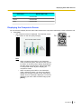
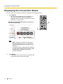
Video Conference Call Screen
A
B
C
F
D
G
E
Other party’s information
When registered in the contact list: The other party’s name/group name is displayed.
When not registered in the contact list: The other party’s IP address, SIP URI (SIP user name@SIP domain
name), host name (e.g., www.example.com), MCU’s conference room number@IP address, or MCU’s SIP
user name@IP address is displayed. If the other party uses the same SIP domain as you, only the SIP
user name, and not the SIP URI, is displayed.
Video Image
Displays the other party’s video, your own video, or video from the secondary video input such as a
computer display or a sub video camera (Page 64, Page 68).
Subscreen
Depending on the screen layout, your own video or the other party’s video is displayed here (Page 47,
Page 49, Page 52).
Duration
Displays the duration of the current video conference call.
Note
•
99h59m is displayed for the duration even if the length of the video conference call exceeds 100
hours.
Guide
Displays operations you can perform with the remote control.
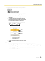
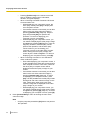
Network Status Indication
The number of antennas in the icon indicates differing levels of network congestion.
The icon changes as follows:
0 bars (
): The network is very congested.
1 bar (
): The network is congested.
2 bars (
): The network is slightly congested.
3 bars (
): The network is not congested.
Note
•
•
32
If the icon shows only 0–1 bars continuously, contact your network administrator.
During multiple-party video conference calls, the icon is displayed on each site screen, but not on
your own image.
User Manual
Preparation
•
You can set whether to display the icon. This setting affects all displayed images (excluding your
own image) (Page 87). For example, if icon display has been enabled, the icon will be displayed
on the image of all other parties, but not on your own image. However, if icon display has been
disabled, the icon will not be displayed on any of the images.
Status Indication
The status of the unit is displayed with an icon (Page 29).
Note
•
*1
Pressing [Full Screen] on the remote control will hide or unhide the other party’s information, duration,
network status indication*1, and guide displays.
If the network status indication has been set to not be displayed, pressing [Full Screen] will not show the icon.
User Manual
33
Starting a Video Conference
S
t
a
r
Making a Video Conference Call
t
You can make a video conference call using one of the following methods.
i
n
Note
g
•
a
V
i
•
•
d
e
o
•
•
•
•
C
o
n
f
e
r
•
e
n
c
•
e
•
•
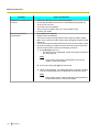
During a video conference call, you cannot perform the following operations:
– Pressing [Menu] to display the Menu screen.
– Pressing [Contact] to display the contact list screen.
Make sure that peripheral devices (e.g., display, main video camera) are turned on.
If a called party does not answer a video conference call within approximately 60 seconds, the call will
be terminated automatically.
2-party/3-party/4-party video conference calls can be made using the outgoing call history.
Only 2-party video conference calls can be made using the incoming call history.
You cannot add parties to an existing video conference call.
During a 3-party/4-party video conference call, even if only one party ends the video conference call,
the rest of the parties will also be disconnected.
A video conference call will start with only the parties that answered the call. For example, if only one
party answers a 4-party video conference call, the video conference call will start as a 2-party video
conference call.
3-party/4-party video conference calls may not be possible depending on bandwidth settings
(Page 85, Page 105).
Video conference calls can be made using a SIP URI through a SIP server only when in IP Mode and
if SIP settings have been made correctly.
When connecting to non-Panasonic video conference systems, you can make only 2-party video
conference calls.
Calling Using Speed Dial (2-party Conference/3-party Conference/
4-party Conference)
Note
•
34
To call using speed dial, you need to have a speed dial number programmed in "Speed Dial" in the
contact list (Page 79).
User Manual
Starting a Video Conference
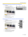
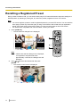
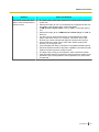
Calling from the Home Screen (Operation with the Main Unit)
1
2
Press [Home].
• The Home screen is displayed.
1
2
3
4
Press [One-Touch Connection] (1 to 5).
The LED for the One-Touch Connection number
you pressed lights up.
• The information registered to the selected
One-Touch Connection number is displayed.
•
3
Press [Start] to start the call.
4
When you want to end the call, press [End].
• The Home screen is displayed.
Calling from the Home Screen (Operation with the Remote Control)
1
Press [Home].
• The Home screen is displayed.
2
With the dial keys, enter a One-Touch Connection number
(1 to 5).
• The information registered in the selected One-Touch
Connection number is displayed.
3
4
1
2
3
4
Press [Start] to start the call.
• You can also start the call pressing [Enter].
When you want to end the call, press [End].
The Home screen is displayed.
•
User Manual
35
Starting a Video Conference
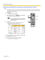
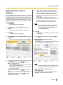
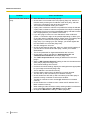
Calling from the Menu Screen (Operation with the Remote Control)
Note
•
From the Menu screen, you can make a video conference call using up to 300 speed dial numbers
(1 to 300). (From the Home screen, you can make a video conference call using up to 5 One-Touch
Connection numbers [1 to 5].)
1
Press [Menu].
• The Menu screen is displayed.
2
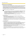
Select "Contact List" using [ ][ ] and press [Enter].
• The contact list screen is displayed.
Note
•
36
If you press [G], the contact list modification
screen will be displayed and the entry can be
modified (Page 80).
3
Press [Y].
• The speed dial screen is displayed. Entries are
displayed in speed dial number order.
4
With the dial keys, enter a speed dial number (1 to 300).
5
Press [Start] to start the call.
6
When you want to end the call, press [End].
• The Home screen is displayed.
User Manual
1
5
2
6
3
4
Starting a Video Conference
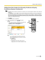
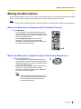
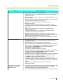
Calling from the Contact List (2-party Conference/3-party
Conference/4-party Conference)
Note
•
•
To make a video conference call from the contact list, you must first register contacts in the contact list
(Page 79).
If "IP Address" is set to "Auto" on the network settings screen (Page 84), the unit’s IP address will
be automatically obtained using a DHCP server, and therefore may change to a different IP address
from the one registered in the other party’s contact list. In such cases, when the other party tries to call
you by selecting a registered IP address from their contact list, the call will not be connected. For details,
contact your network administrator.
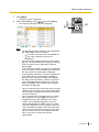
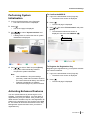
1
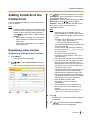
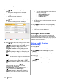
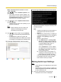
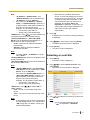
Press [Menu].
• The Menu screen is displayed.
2
Select "Contact List" using [ ][ ] and press
[Enter].
• The contact list screen is displayed. The entries are
grouped in the index tabs and displayed in
alphabetical order of "Group/Site".
1
4
2, 3
5
3
Note
•
You can also open the contact list screen by
pressing [Contact] while the following screens
are displayed:
– Home screen
– Menu screen
– Computer’s screen/sub video camera’s
image (when not on a video conference call)
User Manual
37
Starting a Video Conference
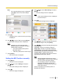
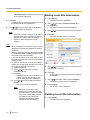
3
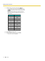
Select the entry you want to call using [ ][ ].
• You can switch the index tab back and forth using
[ ][ ]. (Index tabs in which no entries exist will be
skipped.)
• Press a numeric button on the remote control to
switch to the index tab assigned to that button, as
shown below.
Numeric button
Index Tab
1
–
2
ABC
3
DEF
4
GHI
5
JKL
6
MNO
7
PQRS
8
TUV
9
WXYZ
0
0-9
-&!/
#
4
5
Press [Start] to start the call.
When you want to end the call, press [End].
The Home screen is displayed.
•
38
–
User Manual
Starting a Video Conference
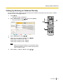
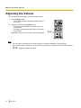
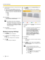
Calling by Entering an Address Directly
You can make a video conference call by entering the IP address, SIP URI (or SIP user name), or MCU’s
conference room number@IP address.
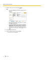
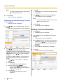
1
Press [Menu].
The Menu screen is displayed.
•
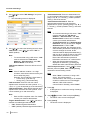
2
Select "Manual Dial" using [ ][ ] and press [Enter].
• The input screen is displayed.
1
7
2-5
8
6
3
Select "Multi-Point" using [
4
Select one of the following values using [
2-party video conference call: "No"
3-party video conference call: "2 sites"
4-party video conference call: "3 sites"
][
].
][
].
Note
•
5
When connecting to an MCU or non-Panasonic video
conference system, you cannot make 3-party/4-party
video conference calls.
Select "Site 1", "Site 2", "Site 3" using [
][
].
User Manual
39
Starting a Video Conference
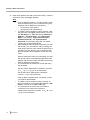
6
Enter the IP address, SIP URI (or SIP user name), or MCU’s
conference room number@IP address.
Note
•
•
•
•
If the IP address contains 1 or 2 digit numbers, enter
these numbers as they are. Do not enter like [.001].
Example: The IP address is [192.168.0.1].
– Correct entry: [192.168.0.1]
– Wrong entry: [192.168.000.001]
To initiate a video conference call by entering a SIP
URI (SIP user name@SIP domain name), you must
set "SIP Server" to "ON" and specify "SIP Server
Address", "SIP Username", and "SIP Domain
Name". Also, specify "Digest Authentication",
"Authentication ID", and "Authentication
Password" as necessary (Page 99). For details,
contact your network administrator.
When making a video conference call within your own
SIP domain, you can make the call by entering the
other party’s SIP user name. When the other party is
not within your SIP domain, you must also include
their SIP domain name in addition to their SIP user
name.
When a SIP domain name is not specified, your own
SIP domain name is automatically appended to the
address and the call is made. Be careful as this may
result in calling the wrong party.
The characters that can be input for SIP URI entry
are as follows:
SIP user name: alphanumeric characters, symbols .
= * + _ - $ ! ? / ' ( ) (up to 60 characters)
SIP domain name: alphanumeric characters,
symbols . - (up to 128 characters)
•
•
40
User Manual
Enter an RFC-compliant value. For details, contact
your network administrator.
To initiate a video conference call by entering an
MCU’s conference room number@IP address, "SIP
Server" must be set to "OFF" (Page 99).
The characters that can be input for an MCU’s
conference room number are as follows:
Alphanumeric characters, symbols . = * + _ - $ ! ? /
' ( ) (up to 60 characters)
Starting a Video Conference
•
You can refer to the contact list when entering the IP
address, SIP URI (or SIP user name), or MCU’s
conference room number@IP address, by following
the procedure below (You cannot enter a destination
using the call history.):
1. Press [G].
• The contact list screen is displayed.
2. Use [ ][ ] to select the contact you want to
refer to.
• You can use [ ][ ] or the numeric buttons
of the remote control to select the displayed
tab (Page 38).
3. Press [Enter].
• The display returns to the input screen.
7
Press [Start] to start the call.
• You can also start the call by pressing [Enter].
8
When you want to end the call, press [End].
• The Home screen is displayed.
User Manual
41
Starting a Video Conference
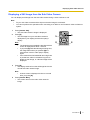
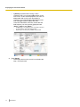
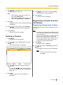
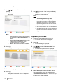
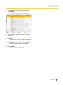
Calling from the Call History
You can make a video conference call from the call history. The call history is divided into outgoing and incoming
calls. The last 30 video conference calls made and received are stored in the outgoing and incoming call history.
Information such as the contact name or IP address (or host name)/SIP URI/MCU’s conference room
number@IP address/MCU’s SIP user name@IP address, the date and time, the duration of the call, and the
result of the call is displayed for each call on the outgoing call history screen and incoming call history screen.
If the IP address/SIP URI/MCU’s conference room number@IP address of an entry in the call history is deleted
from or edited in the contact list, the contact name in the call history entry will be replaced by the IP address/
SIP URI/MCU’s conference room number@IP address.
Note
•
•
In IP mode, to initiate a video conference call from a SIP URI (SIP user name@SIP domain name) or
a SIP user name displayed in the call history, you must set "SIP Server" to "ON" and specify "SIP
Server Address", "SIP Username", and "SIP Domain Name". Also, specify "Digest
Authentication", "Authentication ID", and "Authentication Password" as necessary (Page 99).
For details, contact your network administrator.
If the other party uses the same SIP domain name as you, only the SIP user name, and not the SIP
URI (SIP user name@SIP domain name) will be displayed in the call history.
Outgoing Call History:
• 2-party/3-party/4-party video conference calls can be made using the outgoing call history.
• When connecting to non-Panasonic video conference systems, you can make only 2-party video
conference calls using the outgoing call history.
• For video conference calls made using the contact list, the contact name is displayed. For video conference
calls made by entering the IP address/SIP URI/MCU’s conference room number@IP address directly
(Page 39), that information is displayed. (That information is displayed even if a matching entry exists in
the contact list.)
• If consecutive video conference calls are made to the same destination, only the latest call will appear in
the outgoing call history.
Incoming Call History:
• Only 2-party video conference calls can be made using the incoming call history.
• If the calling party’s IP address/SIP URI/MCU’s conference room number@IP address is registered in the
contact list, the contact name is displayed. Otherwise, the IP address (or host name)/SIP URI/MCU’s
conference room number@IP address/MCU’s SIP user name@IP address is displayed.
• Depending on the type of MCU, a video conference call may be received from the MCU’s SIP user
name@IP address rather than the MCU’s conference room number@IP address. In that case, you directly
cannot call the MCU’s conference room from this incoming call history.
• If consecutive unanswered video conference calls are received from the same party, only the latest call
will appear in the incoming call history.
• You cannot make a video conference call to a host name displayed in the incoming call history.
• You may not be able to initiate video conference calls with SIP URIs (or SIP user names) in the incoming
call history for a reason such as non-compliance with the RFC. In this case, contact your network
administrator.
42
User Manual
Starting a Video Conference
1
2
Press [Menu].
• The Menu screen is displayed.
Select "Call History" using [ ][ ] and press [Enter].
The outgoing call history screen is displayed.
•
1
4
2, 3
5
Note
•
•
•
•
•
•
The result of the video conference call is displayed in
the "Call result" column as follows:
: The video conference call was established.
–
–
: The video conference call was not
established.
To move to the incoming call history screen, press
[G]. You can switch between the outgoing call history
screen and the incoming call history screen by
pressing [G].
In the incoming call history, if a party is not registered
in your contact list, their IP address (or host name)/
SIP URI (or SIP user name) will be displayed.
In the outgoing call history, if a party is registered in
your contact list, the contact name is displayed.
However, when calling by entering an IP address,
SIP URI (or SIP user name), or MCU’s conference
room number@IP address (Page 39), even if the
party is registered in your contact list, the entered
information is displayed.
When a contact in the incoming call history is newly
added to your contact list, the incoming call history
will be updated to display the contact’s information
from the contact list.
When a party that is not registered in your contact
list is selected, if you press [B], the contact list
registration screen will be displayed and a new
contact can be registered (Page 81). If a host
name is displayed in the "Site" column, the party
cannot be registered in your contact list. Also, you
may not be able to register a SIP URI (or SIP user
name) from the incoming call history to the contact
list for a reason such as non-compliance with the
RFC. In this case, contact your network
administrator.
User Manual
43
Starting a Video Conference
3
Select the party you want to call using [
][
].
Note
•
If you press [Enter], the call history details screen is
displayed.
•
When not selecting a local site (Page 107), "Local
site name" will be blank.
The lowest bandwidth for the maximum bandwidth
setting among all participating parties is displayed in
"Bandwidth". If the video conference call was not
established, the maximum bandwidth will be blank.
Depending on the other party, "Device type" may be
blank.
•
•
44
4
Press [Start] to start the call.
5
When you want to end the call, press [End].
• The Home screen is displayed.
User Manual
Starting a Video Conference
Answering a Video Conference Call
Depending on your setting, you can either respond to a request to participate in a video conference call
manually (manual answer) or automatically (automatic answer) (Page 85).
Note
•
Make sure that peripheral devices (e.g., display, main video camera) are turned on.
When Manual Answer is Set
When a video conference call is incoming there will be an incoming call ring, and a dialogue box is displayed.
When the caller is registered in the contact list, the caller’s
group/site is displayed.
When the caller is not registered, the caller’s IP address (or
host name)/SIP URI is displayed.
Note
•
•
If the other party uses the same SIP domain name as you, only the SIP user name, and not the SIP
URI (SIP user name@SIP domain name) is displayed.
If the caller’s group/site name, or SIP URI (or SIP user name) is too long to display, it will be shortened
and ended with "..." .
Operation with the Main Unit
1
Press [Start].
• The video conference begins.
1
Operation with the Remote Control
1
Press [Start].
• You can also answer the video
conference call by pressing [Enter].
• The video conference begins.
1
User Manual
45
Starting a Video Conference
Note
•
If you do not answer a video conference call within approximately 60 seconds, the call will be terminated
automatically.
When Automatic Answer is Set
When a video conference call is incoming the call will be automatically answered after one ring, and
transmission then begins.
46
User Manual
Changing the Screen Layout
C
h
a
n
g
i
Changing the Screen Layout during a 2-party Video
Conference Call
n
g
t
You can choose from 3 different screen layouts when taking part in a 2-party video conference call.
1
Press [Layout].
The screen will cycle through the available layouts
each time you press [Layout].
– Layout 1: The other party’s image is displayed
full screen.
– Layout 2: The other party’s image is displayed
full screen, and your own image is displayed in
the upper right subscreen.
– Layout 3: Your own image is displayed full
screen.
•
h
e
S
c
r
e
e
n
L
a
1
y
Layout 1
Layout 2
o
u
t
B
A
A
Layout 3
B
A: Other Site
B: This Site
Note
•
You can press [B] or [R] to switch the screen layout to that button’s pre-assigned layout.
The layout displayed by each button depends on the screen layout currently in use.
Display
Other Site
Screen Layout
Layout 1
User Manual
47
Changing the Screen Layout
Display
Screen Layout
Both Sites
Layout 2
This Site
Layout 3
Example: When using Layout 2
•
•
48
[B]: The screen layout will be switched to Layout 3.
[R]: The screen layout will be switched to Layout 1.
When connecting to an MCU or non-Panasonic video conference system, images received from the
other party may not be displayed in the correct aspect ratio (the ratio of the width of the image to its
height). In this case, perform the following operation during the video conference call. (When the video
conference call ends, the aspect ratio will return to "Auto" [default].)
1. Press [G].
• The aspect ratio dialogue box is displayed.
2. Use [ ][ ] to select "Auto" (default), "16:9", or "4:3".
• A dialogue box showing the selected aspect ratio is displayed for about 3 seconds.
When connecting to an MCU, the MCU’s screen will be displayed as the other party’s image. You can
change the MCU’s screen layout remotely using tone signals (Page 78).
User Manual
Changing the Screen Layout
Changing the Screen Layout during a 3-party Video
Conference Call
You can choose from 7 different screen layouts when taking part in a 3-party (This Site, Site 1, Site 2) video
conference call.
1
Press [Layout].
The screen will cycle through the available layouts
each time you press [Layout].
– Layout 1: Image of Site 1 on the left and image
of Site 2 on the right.
– Layout 2: The images are displayed as follows:
Site 1: upper left
Site 2: upper right
This Site: bottom middle
– Layout 3: Image of Site 1 is displayed full screen
and image of Site 2 is displayed in the upper right
subscreen.
– Layout 4: Image of Site 2 is displayed full screen
and image of Site 1 is displayed in the upper left
subscreen.
– Layout 5: The image of Site 1 is displayed full
screen.
– Layout 6: The image of Site 2 is displayed full
screen.
– Layout 7: Your own image is displayed full
screen.
•
1
User Manual
49
Changing the Screen Layout
Layout 1
Layout 2
A
A
B
B
C
Layout 7
Layout 3
C
A
Layout 6
Layout 4
B
A
B
B
Layout 5
A
50
User Manual
A: Site 1
B: Site 2
C: This Site
Changing the Screen Layout
Note
•
You can press [B], [R], or [G] to switch the screen layout to that button’s pre-assigned layout.*1 The
layout displayed by each button depends on the screen layout currently in use.
*1
You cannot switch the screen layout to Layout 2 directly. However, you can switch to Layout 2 if you press [Layout] first
(Page 49).
Display
Screen Layout
Side by Side
Layout 1
Site 1(2)
Layout 3
(Site 1) 2
Layout 4
Site 1
Layout 5
Site 2
Layout 6
This Site
Layout 7
Example: When using Layout 3
[B]: The screen layout will be switched to Layout 5.
[R]: The screen layout will be switched to Layout 6.
[G]: The screen layout will be switched to Layout 7.
User Manual
51
Changing the Screen Layout
Changing the Screen Layout during a 4-party Video
Conference Call
You can choose from 6 different screen layouts when taking part in a 4-party (This Site, Site 1, Site 2, Site 3)
video conference call.
1
52
Press [Layout].
• The screen will cycle through the available layouts
each time you press [Layout].
– Layout 1: The images are displayed as follows:
Site 1: upper left
Site 2: bottom middle
Site 3: upper right
– Layout 2: The images are displayed as follows:
Site 1: upper left
Site 2: lower left
Site 3: upper right
This Site: lower right
– Layout 3: The image of Site 1 is displayed full
screen.
– Layout 4: The image of Site 2 is displayed full
screen.
– Layout 5: The image of Site 3 is displayed full
screen.
– Layout 6: Your own image is displayed full
screen.
User Manual
1
Changing the Screen Layout
Layout 1
A
C
B
Layout 2*¹
A
C
B
D
Layout 6
Layout 3
D
A
Layout 5
Layout 4
C
B
A: Site 1
B: Site 2
C: Site 3
D: This site
*1
Image edges are trimmed and the image is centred.
Note
•
You can press [B], [R], or [G] to switch the screen layout to that button’s pre-assigned layout. The
layout displayed by each button depends on the screen layout currently in use.
User Manual
53
Changing the Screen Layout
Display
Screen Layout
Remote sites
Layout 1
All Sites
Layout 2
Site 1
Layout 3
Site 2
Layout 4
Site 3
Layout 5
This Site
Layout 6
Example: When using Layout 3
[B]: The screen layout will be switched to Layout 1.
[R]: The screen layout will be switched to Layout 2.
[G]: The screen layout will be switched to Layout 6.
54
User Manual
Controlling a PTZ Camera
C
o
n
t
Controlling a PTZ Camera
r
o
l
l
If a PTZ (pan, tilt, zoom) camera is connected as the main video camera to the other party’s unit, you can
control the pan (side-to-side movement), the tilt (up-down movement) and the zoom of the camera during a
video conference call.
i
n
Note
•
g
a
P
•
T
Z
•
C
a
•
•
m
e
r
•
a
1
You cannot control your PTZ camera. If the other party is using a KX-VC300 or a KX-VC600, you will
be able to control their PTZ cameras. If the other party is using a KX-VC500, you will not be able to
control their PTZ cameras.
If any of the other parties is using an older software version, you will not be able to control any of the
other party’s PTZ cameras.
You will be able to control the other party’s PTZ cameras only if they have set "CAM ctrl from remote
site(s)" in their settings to "ON" (by default, it is set to "OFF").
For details about compatible PTZ camera models, contact your dealer.
The features that can be used may be limited depending on your video camera model.
(e.g., A video camera with only a zoom feature)
When the other party is using a non-Panasonic video conference system, some operations may not
be available, or unintended operations may occur.
Press [CAM Ctrl].
• The site selection dialogue box is displayed.
Note
•
After the site selection dialogue box is displayed,
if no operations are performed within
approximately 3 seconds, the dialogue box will
disappear.
User Manual
55
Controlling a PTZ Camera
2
56
Use [ ][ ] to select the site to display and press
[Enter].
• The camera control screen is displayed.
User Manual
Controlling a PTZ Camera
3
Press the buttons of the remote control to operate the
PTZ camera.
[B]: Zoom out
[R]: Zoom in
[ ][ ]: Pan the camera left/right.
[ ][ ]: Tilt the camera up/down.
•
•
The movement continues as long as you hold down
the button, and stops when you release the button.
For finer control of the movement, press the button
and immediately release it, and repeat this in
succession.
To control another site’s PTZ camera, press [Y].
Each time [Y] is pressed, the order of the sites listed
in the site selection dialogue box will change.
Example: During a 4-party video conference call
Site 1
Site 2
Site 3
Site 1
Site 2
Site 3
•
To return to the video conference call screen, press
[Back].
Note
•
•
You can press [Full Screen] on the remote control to display/hide the guide area.
In the following cases, you will not be able to control a PTZ camera, even if you press [CAM Ctrl].
– While contents are being shared.
– While displaying the unit information screen or the connections status screen.
– While displaying a dialogue box.
User Manual
57
Controlling a PTZ Camera
Recalling a Registered Preset
During a video conference call, you can set the other party’s PTZ camera’s direction and zoom settings to a
desired position by selecting a preset (pan, tilt, and zoom position) registered in their PTZ camera.
Note
•
•
1
You cannot register a preset or recall a registered preset for your own PTZ camera. You can recall the
other party’s preset only if the other party is using a KX-VC300 or KX-VC600 and has registered a
preset. If the other party is using a KX-VC500, you cannot recall a preset of their PTZ camera.
For details about compatible PTZ camera models, contact your dealer.
Press [CAM Ctrl].
• The site selection dialogue box is displayed.
Note
•
2
58
After the site selection dialogue box is displayed,
if no operations are performed within
approximately 3 seconds, the dialogue box will
disappear.
Use [ ][ ] to select the desired site and press
[Enter].
• The camera control screen is displayed.
User Manual
Controlling a PTZ Camera
3
Press a numeric button (1–9) to select the preset
number that you want to recall.
• The direction and zoom of the other party’s PTZ
camera will change to that of the registered preset.
Note
•
If a number which has no preset registered to it
is selected, the PTZ camera’s direction or zoom
will not change.
User Manual
59
Adjusting the Volume and Tone
A
d
j
u
Adjusting the Volume
s
You can adjust the volume during a video conference call.
t
i
1
Press [Volume (+/–)].
• The volume level bar is displayed at the bottom of
the screen.
2
Adjust the volume using [Volume (+/–)].
• Pressing [+] will increase the volume of the other
party’s voice.
• Pressing [–] will decrease the volume of the other
party’s voice.
n
g
t
h
e
V
o
l
u
After about 3 seconds, the volume level bar disappears.
1, 2
m
e
a
n
d
Note
T
•
•
o
n
e
•
60
You can set the volume level of a video conference call before starting the call (Page 88).
After ending a video conference call, the volume level returns to the volume level set before starting
the call.
You cannot adjust the display’s volume.
User Manual
Adjusting the Volume and Tone
Muting the Microphone
During a video conference call, you can mute the microphone so that your voice cannot be heard by the other
party. You will be able to hear the other party’s voice, but they will not be able to hear you.
Note
•
You can set the microphone(s) to be mute at the start of a received video conference call (Page 86).
Muting the Microphone (Operation with the Remote Control)
1
Press [MIC Mute].
An icon appears in the status display area of the
screen (Page 29), and the LED light on the Boundary
Microphone (Page 21) becomes red. Make sure the
colour of the LED changes.
• Pressing [MIC Mute] again will unmute the
microphone. The LED light on the Boundary
Microphone (Page 21) becomes green. Make sure
the colour of the LED changes.
•
1
Muting the Microphone (Operation with the Boundary Microphone)
1
Press the MIC Mute button.
• An icon appears in the status display area of the
screen (Page 29), and the LED light on the Boundary
Microphone (Page 21) becomes red. Make sure the
colour of the LED changes.
• Pressing the MIC Mute button again will unmute the
microphone. The LED light on the Boundary
Microphone (Page 21) becomes green. Make sure
the colour of the LED changes.
1
Note
•
When multiple Boundary Microphones are
connected, pressing the MIC Mute button of
one Boundary Microphone will mute all
Boundary Microphones.
User Manual
61
Adjusting the Volume and Tone
Reducing Microphone Noise
You can reduce the amount of ambient noise picked up by the microphone (shuffling of papers, etc.) during a
video conference call. When noise reduction is in effect, the volume level of voices may also be reduced.
1
Press [Y].
• "Whisper Mode [ON]" is displayed, and noise
reduction is enabled.
1
•
Pressing [Y] again will display "Whisper Mode
[OFF]", and noise reduction is disabled.
Note
•
•
62
User Manual
You can set whether to enable noise reduction
for a video conference call before starting the
call (Page 87).
After a video conference call is finished, the
noise reduction setting returns to the value set
before starting the call.
Adjusting the Volume and Tone
Adjusting the Tone
You can adjust the tone during a video conference call.
1
Press [Tone ( / )].
The tone control dialogue box appears, and the
current tone setting is displayed.
•
1, 2
2
Press [Tone ( / )] to select a tone setting.
• "More Highs": high-pitched sounds are amplified.
• "Standard": regular (default) sound.
• "More Lows": low-pitched sounds are amplified.
• "Voice": makes voices easier to hear when there is
a high level of ambient noise.
• "Music": makes sounds with a broad frequency,
such as music, easier to hear.
After about 3 seconds, the tone control dialogue box
disappears.
Note
•
•
•
You can set the tone of a video conference call before starting the call (Page 88).
After a video conference call is finished, the tone setting returns to the value set before starting the
call.
When connecting to an MCU or non-Panasonic video conference system, the tone is set to
"Standard" and cannot be changed.
User Manual
63
Displaying Other Video Sources
D
i
s
p
Displaying a Computer’s Screen
l
You can display a computer’s screen on your display and to other parties by connecting the computer to the
unit.
This is convenient when explaining something on the computer’s screen while showing it to others, for example.
a
y
i
n
Main video camera
g
Computer
O
t
h
e
r
V
i
d
e
Router
o
S
o
u
DCE *1
r
DCE *1
c
e
Internet
s
*1
DCE: Data Circuit-terminating Equipment
Connecting the Computer
•
•
•
•
•
64
Connect your computer’s monitor output to the back of the unit using a VGA cable (Page 19).
Make sure the cable used has the correct connector shapes to connect to both your computer and to the
unit.
You can connect or disconnect the computer during a video conference call.
You can only display one computer’s screen at a time.
The computer screen resolutions supported by the unit are VGA (640 ´ 480), SVGA (800 ´ 600), and XGA
(1024 ´ 768).
SXGA (1280 ´ 1024) is not supported. For each resolution, the following settings are supported:
User Manual
Displaying Other Video Sources
Resolution
Refresh Rate (Hz)
VGA
60/72/75/85
SVGA
60/72/75/85
XGA
60/70/75/85
Displaying the Computer’s Screen
You can switch the display from the main video camera to the computer screen during a video conference call.
1
Press [PC].
• The computer’s screen is displayed. The computer screen
is also shown on the other party’s display.
1
2
Note
•
•
When connecting to an MCU or non-Panasonic
video conference system, the same screen may not
be shown on the other party’s display depending on
the other party’s screen layout. Ask the other party
to change their screen layout to display your
computer’s screen.
When connecting to an MCU or non-Panasonic
video conference system, you may not be able to
display the computer’s screen on the other party’s
display. An error message is displayed. To return to
displaying your main video camera’s image, press
[Enter].
User Manual
65
Displaying Other Video Sources
•
•
•
2
Pressing [Full Screen] on the remote control will
hide or unhide the other party’s information,
duration, and guide displays.
When connecting to another Panasonic HD Visual
Communication Unit:
– While displaying your computer’s screen, the
other party cannot press [PC] to display their
own computer’s screen.
– If a sub video camera is connected, you can also
switch to the sub video camera’s image by
pressing [Camera Sub] (Page 68). Only the
party that pressed [PC] can perform this
operation. To return to displaying your
computer’s screen, press [PC].
– While displaying your computer’s screen, you
can switch to displaying the other party’s image
in Layout 1 by pressing [B] (Page 47, Page 49,
Page 52). However, the other party cannot
perform this operation, and the other party
cannot confirm if you are viewing your
computer’s screen or the other party’s image.
When viewing the other party’s image, the
screen layout is fixed to Layout 1. To return to
displaying your computer’s screen, press [B].
When connecting to an MCU or non-Panasonic
video conference system:
– Even while displaying your computer’s screen, it
is also possible for the other party to start sharing
their computer’s screen. In this case, note that
the other party’s computer screen will be
displayed as the other party’s image on your
screen.
– If a sub video camera is connected, you can also
switch to the sub video camera’s image by
pressing [Camera Sub] (Page 68). To return
to displaying your computer’s screen, press
[PC]. It is also possible for the other party to start
sharing their sub video camera’s image. In this
case, note that the other party’s sub video
camera’s image will be displayed as the other
party’s image on your screen.
– While displaying your computer’s screen, you
can switch to displaying the other party’s image
in Layout 1 by pressing [B] (Page 47). To return
to displaying your computer’s screen, press [R].
Press [Camera Main] to return to showing the main video
camera’s image.
Note
•
66
User Manual
Only the party that pressed the [PC] button can perform
this operation.
Displaying Other Video Sources
Note
•
On the Home screen, you can also display the computer’s
screen on your display by pressing [PC]. While the
computer’s screen is displayed, the unit will not enter screen
standby mode. To return to the Home screen, press [Camera
Main].
User Manual
67
Displaying Other Video Sources
Displaying the Sub Video Camera’s Image
When a sub video camera is connected to the unit, you can display the sub video camera’s image on your
display and to other parties.
Main video camera
Sub video camera
Router
DCE *1
DCE *1
Internet
*1
DCE: Data Circuit-terminating Equipment
Connecting the Sub Video Camera
•
•
•
•
68
Connect a video camera to the back of the unit using an HDMI cable (Page 19).
You can connect or disconnect the sub video camera during a video conference call.
You can only display the image of one sub video camera at a time.
Only video cameras that can output 1080i resolution using HDMI can be used.
User Manual
Displaying Other Video Sources
Displaying the Sub Video Camera’s Image
You can switch the display from the main video camera to a sub video camera during a video conference call.
1
Press [Camera Sub].
• The sub video camera’s image is displayed. The image is
also visible on the other party’s display.
1
Note
•
When connecting to an MCU or non-Panasonic
video conference system, the same image may not
be shown on the other party’s display depending on
the other party’s screen layout. Ask the other party
to change their screen layout to display your sub
video camera’s image.
•
Pressing [Full Screen] on the remote control will
hide or unhide the other party’s information,
duration, and guide displays.
When connecting to another Panasonic HD Visual
Communication Unit:
– While displaying your sub video camera’s
image, the other party cannot press [Camera
Sub] to display their own sub video camera’s
image.
– If a computer is connected you can also switch
to the computer screen’s image by pressing
[PC] (Page 64). Only the party that pressed
[Camera Sub] can perform this operation. To
return to displaying your sub video camera’s
image, press [Camera Sub].
– While displaying your sub video camera’s
image, you can switch to displaying the other
party’s image in Layout 1 by pressing [B]
(Page 47, Page 49, Page 52). However, the
other party cannot perform this operation, and
the other party cannot confirm if you are viewing
your sub video camera’s image or the other
party’s image. When viewing the other party’s
image, the screen layout is fixed to Layout 1. To
return to displaying your sub video camera’s
image, press [B].
•
2
User Manual
69
Displaying Other Video Sources
•
2
When connecting to an MCU or non-Panasonic
video conference system:
– Even while displaying your sub video camera’s
image, it is also possible for the other party to
start sharing their sub video camera’s image. In
this case, note that the other party’s sub video
camera’s image will be displayed as the other
party’s image on your screen.
– If a computer is connected, you can also switch
to the computer screen’s image by pressing
[PC] (Page 64). To return to displaying your sub
video camera’s image, press [Camera Sub]. It
is also possible for the other party to start sharing
their computer’s screen. In this case, note that
the other party’s computer screen will be
displayed as the other party’s image on your
screen.
– While displaying your sub video camera’s
image, you can switch to displaying the other
party’s image in Layout 1 by pressing [B]
(Page 47). To return to displaying your sub video
camera’s image, press [R].
Press [Camera Main] to return to showing the main video
camera’s image.
Note
•
Only the party that pressed [Camera Sub] can perform
this operation.
Note
•
70
On the Home screen, you can also display the sub video
camera’s image on your display by pressing [Camera Sub].
While the sub video camera’s image is displayed, the unit will
not enter screen standby mode. To return to the Home
screen, press [Camera Main].
User Manual
Displaying Other Video Sources
Displaying a Still Image from the Sub Video Camera
You can display a still image from the sub video camera during a video conference call.
Note
•
•
1
Fix your sub video camera and the object so that the image is not blurred.
You cannot perform this operation when connecting to an MCU or non-Panasonic video conference
system.
Press [Camera Sub].
The sub video camera’s image is displayed.
•
2
Press [R].
• The still image from your sub video camera is
displayed on your display and the other party’s
display.
Note
•
•
•
3
1
4
2
3
The image becomes gradually clear after a black
screen is displayed for about 1 second.
If you press [R] while the still image is being sent,
the image taken when you pressed [R] the
second time is sent to other party’s display
again.
If the network has low bandwidth and a high rate
of packet loss, either it will take a long time to
display a clear image, or a blurred image will be
displayed.
Press [G].
• The display switches from the still image back to the
normal sub video camera image.
Note
•
4
A black screen is displayed for about 1 second
after you press [G].
Press [Camera Main].
• The screen returns to the main video camera’s
image.
User Manual
71
Displaying the Connection Status
D
i
s
p
Displaying the Connection Status
l
You can confirm the connection status of the network and peripheral devices.
a
1
y
i
n
g
t
Press [Status].
• The connections status screen is displayed. An
"X" mark is displayed next to any network or
peripheral devices connection that is not in normal
operation or not connected.
h
Example: The Boundary Microphone connection is
not normally operating.
e
C
2
o
n
n
e
1
c
t
i
o
n
S
t
a
t
u
Note
s
•
•
2
72
"MIC" displays the connection status of the
Boundary Microphone only. The connection
status of general-purpose microphones is not
displayed.
If the MIC detection setting has been disabled
through system settings, the connection status
of the Boundary Microphone will not be
displayed (Page 87).
Press [Back].
• The display returns to the screen in use before the
connections status screen was viewed.
User Manual
Displaying the Connection Status
Displaying Unit Information
1
Press [Status] twice.
• The unit information screen is displayed.
2
1
Note
•
•
When you are not using a SIP server, "SIP
Username" and "SIP Domain Name" will be
blank.
The status of communication encryption is
displayed under "Encryption" and the
resolution for sending images is displayed under
"Resolution (send)". This information is not
displayed when communication is not occurring.
User Manual
73
Displaying the Connection Status
•
If [Status] is pressed twice during a video
conference call, you can press [R] to switch to the
next screen. That screen displays the unit name, IP
address/SIP URI (or SIP user name)/MCU’s
conference room number@IP address/MCU’s SIP
user name@IP address, packet loss rate,
connection bandwidth, resolution, frame rate and
field frequency for the 3 parties displayed under
"Site 1", "Site 2" and "Site 3".*1*2
*1
*2
2
74
"Frequency" is not displayed when connecting to an MCU
or non-Panasonic video conference system.
Depending on the other party, "Name" may be blank.
Press [Back].
• The display returns to the screen in use before the
step 1 was performed.
User Manual
About Enhanced Features
A
b
o
u
Activating Enhanced Features
t
E
n
h
a
n
Overview of Activation Keys
You can enhance the following types of features with an activation key (sold separately). For details about the
settings, refer to Page 101.
c
e
Model No.
Product Name
Activation Key Type
Description
d
F
KX-VCS101
e
a
Activation Key Card
(Connection
Enhancement)
Connection Enhancement
Enables the connection to MCUs
and non-Panasonic video
conference systems.
t
u
r
Note
•
e
s
•
Once you have activated new features (Page 101), they remain activated even after software updates
or a system initialisation.
If the hardware changes, for example if you exchange the unit, you must reacquire the registration key
and activate the features again. In this case, the registration key can be reacquired free of charge.
User Manual
75
About Enhanced Features
Enabling Connection to Non-Panasonic Video Conference
Systems
You can connect to a non-Panasonic video conference system and have a 2-party video conference call.
Intranet
Note
•
•
•
•
•
•
•
•
•
•
•
•
•
76
To connect to non-Panasonic video conference systems, you must purchase an activation key card
(KX-VCS101) and activate this feature beforehand (Page 101). For details about the activation key,
contact your dealer.
Non-Panasonic video conference systems you want to connect to must meet the following criteria.
Confirm the settings of the non-Panasonic video conference system.
– Supports SIP communication
– Supports communication with the H.264 Baseline Profile
– Supports communication with the G.722, G.722.1, and G.722.1 Annex C voice codecs
For details about the types of non-Panasonic video conference systems you can connect to, contact
your dealer.
Video conference calls to a non-Panasonic video conference system through a SIP server using a SIP
URI are not guaranteed (Page 99). IP addresses must be specified to make calls.
The connection specifications (e.g., resolution) and available functions (e.g., content sharing) differ
depending on the model type you connect to. For details, contact your dealer.
When connecting to non-Panasonic video conference systems, only 2-party video conference calls are
possible.
You cannot adjust the tone during a video conference call.
Audio sent to the other party is monaural.
While you are displaying a sub video camera’s image, you cannot send a still image from the sub video
camera.
Encrypted communication is not supported. When connecting to a non-Panasonic video conference
system, both you and the other party must have encryption disabled (Page 85, Page 97,
Page 97).
Communication cannot be encrypted when you connect to a non-Panasonic video conference system.
Instead, connect over an intranet or via a VPN.
The maximum bandwidth specified in the settings at the beginning of the connection is applied for the
duration of the connection to a non-Panasonic video conference system. Depending on the network
conditions, you must specify an appropriate bandwidth setting (Page 85, Page 105).
It may be necessary to change your maximum bandwidth depending on the non-Panasonic video
conference system you are connecting to. If this is necessary, you can register a maximum bandwidth
in local site settings (Page 105).
User Manual
About Enhanced Features
Enabling Connection to an MCU
Connecting to an MCU allows you to have a video conference call with 5 or more parties.
Intranet
MCU
Note
•
•
•
•
•
•
•
•
•
•
•
•
To connect to an MCU, you must purchase an activation key card (KX-VCS101) and activate this
feature beforehand (Page 101). For details about the activation key, contact your dealer.
MCUs you want to connect to must meet the following criteria. Confirm the settings of the MCU.
– Supports SIP communication
– Supports communication with the H.264 Baseline Profile
– Supports communication with the G.722, G.722.1, and G.722.1 Annex C voice codecs
For details about the types of MCUs you can connect to, contact your dealer.
Video conference calls to an MCU through a SIP server using a SIP URI are not guaranteed
(Page 99). IP addresses must be specified to make calls.
The connection specifications (e.g., resolution) and available functions (e.g., content sharing) differ
depending on the MCU you connect to. For details, contact your dealer.
The procedure for connecting to an MCU differs depending on the MCU. For details, contact your
dealer.
You cannot adjust the tone during a video conference call.
Audio sent to the other party is monaural.
While you are displaying a sub video camera’s image, you cannot send a still image from the sub video
camera.
Encrypted communication is not supported. When connecting to an MCU, encryption must be disabled
on both sides (Page 85, Page 97, Page 97).
Communication cannot be encrypted when you connect to an MCU. Instead, connect over an intranet
or via a VPN.
The maximum bandwidth specified in the settings at the beginning of the connection is applied for the
duration of the connection to an MCU. Depending on the network conditions, you must specify an
appropriate bandwidth setting (Page 85, Page 105).
User Manual
77
About Enhanced Features
Operating an MCU Remotely using Tone Signals
When connecting to an MCU, you can send tone signals by pressing buttons (0–9, #, or ) on the remote
control. Doing so allows you to operate (e.g., change the screen layout) the MCU remotely.
Note
•
•
•
•
1
Tone signals can only be sent when connecting to an
MCU. They cannot be sent between Panasonic HD
Visual Communication Units.
Features and operations that can be performed
remotely will vary depending on the MCU.
If the MCU you are connecting to does not support
tone signals, an error message is displayed.
If the other party sends tone signals to you, sound
may be interrupted or a ringing noise may occur.
Enter a tone signal (0–9, #, or ).
• The input field (A) is displayed.
A
Note
•
•
•
•
78
User Manual
The input field can only contain up to 16
characters. If you input 17 characters, the first
character input will not be displayed in the input
field but all tone signals will be sent.
The input field is not displayed until a tone signal
is entered.
If a tone signal is not entered for about 3
seconds, the input field disappears.
If you enter further tone signals after the input
field has disappeared, the tone signals entered
the previous time are also displayed.
1
Contacts and Settings
Contacts and Settings
Adding Contacts to the
Contact List
You can register the information of up to 300 contacts
in the contact list.
Note
•
If a video conference call is received while data
is being entered, a dialogue box to confirm if you
answer a video conference call is displayed.
Use [ ][ ] to select "Yes" or "No" and press
[Enter].
• When "Yes" is selected, you can answer a
video conference call while any unsaved
data is lost.
• When "No" is selected, you can continue
entering the data.
3. Use [
][ ] to select the following items for input:
"Group/Site": Enter a name for the contact (up to
24 characters) (Page 110).
"Speed Dial": Enter a speed dial number (1–300).
"Multi-Point": Use [ ][ ] to select "No".
"Address": Enter an IP address, SIP URI (or SIP
user name), or MCU’s conference room
number@IP address.
Note
•
•
Registering a New Contact
Registering a Single-party Contact
1. Press [Menu].
• The Menu screen is displayed.
•
2. Use [
][ ] to select "New Contact" and press
[Enter].
• The contact list registration screen is displayed.
•
•
•
When entering an IP address, if the IP
address contains 1 or 2 digit numbers, enter
these numbers as they are. Do not enter like
[.001].
Example: The IP address is [192.168.0.1].
– Correct entry: [192.168.0.1]
– Wrong entry: [192.168.000.001]
The characters that can be input for SIP URI
entry are as follows:
SIP user name: Alphanumeric characters
and the symbols . = * + _ - $ ! ? / ' ( ) (up
to 60 characters)
SIP domain name: Alphanumeric
characters and the symbols . and - (up to
128 characters)
If the other party has the same SIP domain
name as yours, you can register only their
SIP user name. If the other party has a
different SIP domain name from yours, their
SIP domain name must be entered along
with their SIP user name.
If the SIP domain name is not entered, your
own SIP domain name is automatically
appended to the registered contact. This
may result in a different, unintended party
being registered as a contact, so be careful
when entering a contact’s information.
Enter an RFC-compliant value.
For details, contact your network
administrator.
The characters that can be input for an
MCU’s conference room number are as
follows:
Alphanumeric characters, symbols . = * + _
- $ ! ? / ' ( ) (up to 60 characters)
4. Press [G].
• A dialogue box to confirm the saving of settings
is displayed.
5. Use [ ][ ] to select "Yes" and press [Enter].
• The contact list screen is displayed.
User Manual
79
Contacts and Settings
Note
•
To continue entering another contact, press
[B] and repeat steps 3–5.
6. Press [Home].
• The Home screen is displayed.
4. Press [G].
• A dialogue box to confirm the saving of settings
is displayed.
5. Use [ ][ ] to select "Yes" and press [Enter].
• The contact list screen is displayed.
Note
Registering a Multiple-party Contact
1. Press [Menu].
• The Menu screen is displayed.
2. Use [
][ ] to select "New Contact" and press
[Enter].
• The contact list registration screen is displayed.
•
To continue entering another contact, press
[B] and repeat steps 3–5.
6. Press [Home].
• The Home screen is displayed.
Editing Contact Information
1. Press [Menu].
• The Menu screen is displayed.
2. Use [
][ ] to select "Contact List" and press
[Enter].
• The contact list screen is displayed.
3. Use [ ][ ] to select the contact you want to edit.
• You can use [ ][ ] or the numeric buttons of
the remote control to select the displayed tab
(Page 38).
4. Press [Enter].
• The contact list details screen is displayed.
3. Use [
][ ] to select the following items for input:
"Group/Site": Enter a name for the video
conference call (up to 24 characters) (Page 110).
"Speed Dial": Enter a speed dial number (1–300).
"Multi-Point": Use [ ][ ] to select "2 sites" or
"3 sites".
For "Site 1"/"Site 2"/"Site 3": Use the following
procedure to select these from the contact list
screen.
1. Use [ ][ ] to select "Site 1", "Site 2" or
"Site 3".
2. Press [Enter].
• The contact list screen is displayed.
3. Select a contact using [ ][ ].
• You can use [ ][ ] or the numeric
buttons of the remote control to select the
displayed tab (Page 38).
4. Press [Enter].
• The contact list registration screen is
displayed.
80
User Manual
5. Press [G].
• The contact list edit screen is displayed.
Contacts and Settings
6. Use [
][ ] to select the item you want to edit and
make any changes (Page 110).
Note
•
•
When editing a single-party contact, you
cannot edit "Multi-Point".
When editing a multiple-party contact, you
cannot edit "Multi-Point" or "Address".
7. Press [G].
• A dialogue box to confirm the saving of settings
is displayed.
5. Use [ ][ ] to select "Yes" and press [Enter].
• The contact list screen is displayed.
6. Press [Home].
• The Home screen is displayed.
Registering a Contact from the
Call History
Registering a Single-party Contact
8. Use [ ][ ] to select "Yes" and press [Enter].
• The contact list details screen is displayed.
You can register a contact to the contact list from the
call history.
9. Press [Home].
• The Home screen is displayed.
Note
Deleting a Contact
1. Press [Menu].
• The Menu screen is displayed.
2. Use [
][
] to select "Contact List" and press
[Enter].
• The contact list screen is displayed.
•
•
If a host name is displayed in the "Site" column
of the call history, the party cannot be registered
in your contact list.
Also, you may not be able to register a SIP URI
(or SIP user name) from the incoming call
history to the contact list for a reason such as
non-compliance with the RFC. In this case,
contact your network administrator.
1. Press [Menu].
• The Menu screen is displayed.
2. Use [
][ ] to select "Call History" and press
[Enter].
• The outgoing call history screen is displayed.
Note
•
To refer to the incoming call history,
press [G].
3. Use [
][ ] to select the contact you want to
delete.
• You can use [ ][ ] or the numeric buttons of
the remote control to select the displayed tab
(Page 38).
4. Press [R].
• A dialogue box to confirm the deletion is
displayed.
User Manual
81
Contacts and Settings
3. Use [
][ ] to select the single-party entry you
want to add as a contact, and press [B].
• The contact list registration screen is displayed.
•
•
If a host name is displayed in the "Site" column
of the call history, the party cannot be registered
in your contact list.
Also, you may not be able to register a SIP URI
(or SIP user name) from the incoming call
history to the contact list for a reason such as
non-compliance with the RFC. In this case,
contact your network administrator.
1. Press [Menu].
• The Menu screen is displayed.
2. Use [
][ ] to select "Call History" and press
[Enter].
• The outgoing call history screen is displayed.
3. Use [
][ ] to select the multiple-party entry you
want to add as a multiple-party contact, and press
[B].
• The contact list registration screen is displayed.
4. Use [
][ ] to select the necessary items and
input information (Page 110).
Note
•
You cannot edit "Multi-Point" or
"Address".
5. Press [G].
• A dialogue box to confirm the saving of settings
is displayed.
6. Use [ ][ ] to select "Yes" and press [Enter].
• The outgoing or incoming call history screen is
displayed, depending on which of the screens
you displayed in step 2.
7. Press [Home].
• The Home screen is displayed.
Registering a Multiple-party Contact
You can register a multiple-party contact to the contact
list from the outgoing call history.
Note
•
82
When you register a multiple-party contact to
the contact list from the call history, each party
is also registered automatically as a
single-party contact and each IP address/SIP
URI (or SIP user name) is registered in "Group/
Site".
User Manual
4. Use [
][ ] to select the necessary items and
input information (Page 110).
Note
•
You cannot edit "Multi-Point" or
"Address".
5. Press [G].
• A dialogue box to confirm the saving of settings
is displayed.
6. Use [ ][ ] to select "Yes" and press [Enter].
• The call history screen is displayed.
7. Press [Home].
• The Home screen is displayed.
Contacts and Settings
Changing System
Settings
Note
•
If a video conference call is received while data
is being entered, a dialogue box to confirm if you
answer a video conference call is displayed.
Use [ ][ ] to select "Yes" or "No" and press
[Enter].
• When "Yes" is selected, you can answer a
video conference call while any unsaved
data is lost.
• When "No" is selected, you can continue
entering the data.
6. Use [ ][ ] to select "Yes" and press [Enter].
• The system settings screen is displayed.
7. Press [Home].
• The Home screen is displayed.
Setting the Date and Time
1. Press [Menu].
• The Menu screen is displayed.
2. Use [
][ ] to select "Settings" and press
[Enter].
• The system settings screen is displayed.
3. Use [
Setting the Unit Name
][
] to select "Set Date/Time" and press
[Enter].
• The date/time settings screen is displayed.
1. Press [Menu].
• The Menu screen is displayed.
2. Use [
][ ] to select "Settings" and press
[Enter].
• The system settings screen is displayed.
3. Use [
][ ] to select "System Settings" and
press [Enter].
• The unit name setting screen is displayed.
4. Use [
][ ] to select the item and input
information.
• Enter the year (4 digits), month (1–2 digits), day
(1–2 digits), time (24 hour display), and select
the date format (Month/Day/Year, Day/Month/
Year, Year/Month/Day) and hour display format
(12h/24h).
5. Press [G].
• A dialogue box to confirm the saving of settings
4. Enter a unit name (up to 24 characters)
(Page 110).
5. Press [G].
• A dialogue box to confirm the saving of settings
and system restart after saving is displayed.
6. Use [ ][ ] to select "Yes" and press [Enter].
• The system will automatically restart to reflect
changes to system settings.
is displayed.
User Manual
83
Contacts and Settings
Making Network Settings
1. Press [Menu].
• The Menu screen is displayed.
2. Use [
Note
•
•
][
] to select "Settings" and press
[Enter].
• The system settings screen is displayed.
3. Use [
][ ] to select "Network Settings" and
press [Enter].
• The network settings screen is displayed.
"IP Address", "Subnet mask", and
"Default Gateway" can be entered only if
"IP Address" is set to "Manual".
If the value for "IP Address", "Subnet
mask", or "Default Gateway" contains 1 or
2 digits numbers, enter these numbers as
they are. Do not enter like [.001].
Example: The IP address is [192.168.0.1].
– Correct entry: [192.168.0.1]
– Wrong entry: [192.168.000.001]
"DNS Server": Use [ ][ ] to select whether the
IP address information for the DNS servers
("Primary DNS Server", "Secondary DNS
Server") will be obtained automatically from a
DHCP server or will be set manually.
– "Auto" (default): Obtain the IP address
information automatically.
– "Manual": Set the IP address information
manually.
Note
•
4. Use [
][ ] to select the following items for input:
"IP Address": Use [ ][ ] to select whether the
IP address information for this unit ("IP Address",
"Subnet mask", "Default Gateway") will be
obtained automatically from a DHCP server or will
be set manually.
– "Auto" (default): Obtain the IP address
information automatically.
– "Manual": Set the IP address information
manually.
Note
•
Even if you have selected "Auto", you still
may not be able to acquire an IP address
due to problems such as network
congestion. In this case, "Address is not
assigned" is displayed in the upper right of
the Home screen. Contact your network
administrator.
"IP Address": Enter the IP address of the unit.
"Subnet mask": Enter the subnet mask.
"Default Gateway": Enter the IP address of the
default gateway.
84
User Manual
To select "Auto", "IP Address" must be
set to "Auto".
• The DNS server setting is necessary to
check for upgrades and to download the
latest software.
"Primary DNS Server": Enter the IP address of the
primary DNS server.
"Secondary DNS Server": Enter the IP address of
the secondary DNS server.
Note
•
•
"Primary DNS Server" and "Secondary
DNS Server" can be entered only if "DNS
Server" is set to "Manual".
If the value for "Primary DNS Server" or
"Secondary DNS Server" contains 1 or 2
digits numbers, enter these numbers as
they are. Do not enter like [.001].
Example: The IP address is [192.168.0.1].
– Correct entry: [192.168.0.1]
– Wrong entry: [192.168.000.001]
5. Press [G].
• A dialogue box to confirm the saving of settings
is displayed.
6. Use [ ][ ] to select "Yes" and press [Enter].
• The system settings screen is displayed.
Contacts and Settings
7. Press [Home].
• The Home screen is displayed.
Note
•
Making Connection Settings
1. Press [Menu].
• The Menu screen is displayed.
•
2. Use [
•
][ ] to select "Settings" and press
[Enter].
• The system settings screen is displayed.
3. Use [
][
] to select "Call set up" and press
•
[Enter].
• The connection settings screen is displayed.
The maximum bandwidth during a video
conference call adjusts to that of the party
that has set the lowest bandwidth for the
maximum bandwidth setting among all
participating parties.
You cannot select a value that is higher than
the maximum bandwidth set by the dealer.
For details, contact your dealer.
When you make a 3-party video conference
call, select a value of "1.0 Mbps" or higher.
Otherwise, the image quality and the sound
quality cannot be guaranteed.
When you make a 4-party video conference
call, select a value of "1.5 Mbps" or higher.
Otherwise, the image quality and the sound
quality cannot be guaranteed.
"Encryption": Use [ ][ ] to select whether to
enable encryption.
– "ON": Encryption is enabled.
– "OFF" (default): Encryption is disabled.
Note
•
•
•
4. Use [ ][ ] to select the following items for input:
• The following items are displayed over 2 pages.
To view all the items, press [R] to move to the
next page, and press [B] to move to the
previous page. You must save the settings
separately for each screen on which you
changed the settings.
"Answer Mode": Use [ ][ ] to select how to
answer video conference calls ("Manual" [default]
or "Auto") (Page 45).
"Max. Bandwidth": Press [Enter] and use [ ]
[ ] to select the maximum allowed bandwidth to
be used (512 kbps, 768 kbps, 1.0 Mbps,
1.2 Mbps, 1.5 Mbps, 2.0 Mbps, 2.5 Mbps,
3.0 Mbps, 3.5 Mbps, 4.0 Mbps, 4.5 Mbps,
5.0 Mbps, 5.5 Mbps, 6.0 Mbps, 6.5 Mbps,
7.0 Mbps, 7.5 Mbps, 8.0 Mbps, 8.5 Mbps,
9.0 Mbps [default], 10.0 Mbps).
•
Be careful when changing encryption
settings because doing so may cause you
to become unable to communicate with
other parties.
Be aware that if encryption is disabled,
eavesdropping might be possible on
networks that are not secured against such
actions.
If you cannot specify a value for
"Encryption" because the setting is
unavailable, contact your network
administrator.
When connecting to an MCU or
non-Panasonic video conference system,
set "Encryption" to "OFF" because
encryption is not available. Encryption must
be disabled on both sides.
"Video Quality": Use [ ][ ] to select between
prioritising smooth movement or image quality for
video.
– "Motion" (default): Prioritise smooth
movement.
– "Sharpness": Prioritise image quality.
Note
•
•
If one of the other parties is using an older
software version, "Motion" will be selected.
If "Max Resolution" is set to "HD", and
"Video Quality" is changed from
"Motion" to "Sharpness", the setting for
User Manual
85
Contacts and Settings
"Max Resolution" is automatically
changed to "Auto".
"Max Resolution": Use [ ][ ] to select the
maximum display resolution of the main video
camera and sub video camera used during a video
conference call.
– "Full HD": Maximum resolution: 1920 ´ 1080
(This mode switches the display resolution
according to the condition of the network.)
– "HD": Maximum resolution: 1280 ´ 720
(This mode switches the display resolution
according to the condition of the network.)
– "Auto" (default): This mode selects either "Full
HD" or "HD" according to the available
bandwidth.
– "ON": Communication will become audio only
if there is network congestion.
– "OFF" (default): Communication will not
become audio only, even if there is network
congestion.
Note
•
•
•
Note
•
•
•
•
•
Selecting "Auto" or "HD" is recommended.
When "Full HD" is selected, if the other
party has a low bandwidth, the display
resolution may be lower than when "HD" or
"Auto" is selected.
When making a 3-party video conference
call, the main video camera will be
automatically set to "HD", even if you have
specified "Full HD".
When making a 4-party video conference
call, the main video camera and sub video
camera will be automatically set to "HD",
even if you have specified "Full HD".
When "Video Quality" is set to
"Sharpness", only "Full HD" and "Auto"
can be selected.
"Quality of Service": Use [ ][ ] to select
between prioritising sound or images when
bandwidth is low or the network is congested.
– "Audio" (default): When bandwidth is low
sound quality is prioritised, and when the
network is congested sound disturbance is
reduced.
– "Video": Even when bandwidth is low or the
network is congested, image quality is
prioritised.
Note
•
If one of the other parties is using an older
software version, "Audio" will be selected.
"Audio only mode": Use [ ][ ] to select
whether to use only audio communication
(Audio-only mode) in periods of network
congestion. When in Audio-only mode, your image
is not sent to the other party. Instead, a blue screen
is sent.
86
User Manual
•
To select "ON", "Quality of Service" must
be set to "Audio".
Contents cannot be shared while in Audio
only mode.
When connecting to an MCU or
non-Panasonic video conference system,
or when one of the other parties is using an
older software version, communication will
not become audio only even if "Audio only
mode" is set to "ON".
When changing to Audio-only mode, it may
take some time for the blue screen to be
displayed. Until the blue screen is
displayed, the image may become
distorted.
"Still image quality": Use [ ][ ] to select the
display resolution to use when you send still images
from the sub video camera to other parties.
– "Full HD" (default): The resolution of still
images is Full HD.
– "HD": The resolution of still images is HD.
Note
•
•
If the network has low bandwidth and a
high rate of packet loss, selecting
"HD" is recommended. For details,
contact your dealer.
During a 4-party video conference call,
the display resolution will be "HD", even
if you have specified "Full HD".
"Default MIC Mute set": Use [ ][ ] to select
whether to mute the microphone(s) at the start of a
received video conference call.
– "ON": Mutes the microphone(s).
– "OFF" (default): Does not mute the
microphone(s).
"Call Limit time": Enter the maximum length of
time for the duration of a video conference call (in
hours and minutes).
Note
•
•
If you set 0 hours 0 minutes (default), the
call time is unlimited.
If the duration of a video conference call
exceeds the specified length of time, the call
will be automatically disconnected.
Contacts and Settings
"MIC detection": Use [ ][ ] to select whether to
enable the detection of the connection status of the
Boundary Microphones.
– "ON" (default): Enables the detection of
Boundary Microphones.
– "OFF": Disables the detection of Boundary
Microphones.
Note
•
2. Use [
][ ] to select "Settings" and press
[Enter].
• The system settings screen is displayed.
3. Use [
][ ] to select "Standby Setting" and
press [Enter].
• The screen standby settings screen is
displayed.
When not using Boundary
Microphones, set this to "OFF".
"Network Connection Status": Use [ ][ ] to
select whether to display the network status
indication.
– "ON" (default): Displays the network status
indication.
– "OFF": Hides the network status indication.
"Active call Menu": Use [ ][ ] to select whether
to display the guide when a video conference call
begins.
– "ON" (default): Displays the guide.
– "OFF": Hides the guide.
"Noise reduction": Use [ ][ ] to select whether
to enable noise reduction when a video conference
call begins.
– "ON": Enables noise reduction.
– "OFF" (default): Disables noise reduction.
5. Press [G].
• A dialogue box to confirm the saving of settings
is displayed.
6. Use [ ][ ] to select "Yes" and press [Enter].
• The system settings screen is displayed.
7. Press [Home].
• The Home screen is displayed.
Making Screen Standby
Settings
When the unit or remote control are not operated or a
video conference call is not received for a specified
length of time, the unit enters standby mode. You can
set the length of time here.
1. Press [Menu].
• The Menu screen is displayed.
4. Enter the length of time (0–99) in minutes until the
unit enters screen standby mode (default: 10).
Note
•
If you set "0", the unit will not enter screen
standby mode automatically. However, if
you press the remote control’s [Video Out
On/Off] button, the unit will enter screen
standby mode even if "0" is set.
5. Press [G].
• A dialogue box to confirm the saving of settings
is displayed.
6. Use [ ][ ] to select "Yes" and press [Enter].
• The system settings screen is displayed.
7. Press [Home].
• The Home screen is displayed.
Making Sound Settings
1. Press [Menu].
• The Menu screen is displayed.
User Manual
87
Contacts and Settings
2. Use [
][ ] to select "Settings" and press
[Enter].
• The system settings screen is displayed.
Note
•
3. Press [ ].
• The second page is displayed.
4. Use [
][ ] to select "Sound Settings" and press
[Enter].
• The sound settings screen is displayed.
You can listen to a sample of the following
items by pressing [R].
– "Welcome Screen Vol."
– "Ringback Tone Vol."
– "Ring Tone Vol."
6. Press [G].
• A dialogue box to confirm the saving of settings
is displayed.
7. Use [ ][ ] to select "Yes" and press [Enter].
• The system settings screen is displayed.
8. Press [Home].
• The Home screen is displayed.
Setting the MIC Position
You can specify where a Boundary Microphone is
conceptually positioned relative to the display. When
sounds are transmitted to another party, they are played
in accordance with the specified positions, which
creates a stereo environment.
5. Use [
][ ] to select the following items for input:
"Welcome Screen Vol.": Press [Enter] and use
[ ][ ] to select the volume level ("OFF", "Low",
"Medium" [default] or "High") played at the
start-up.
"Ringback Tone Vol.": Press [Enter] and use
[ ][ ] to select the volume level ("OFF", "Low",
"Medium" [default] or "High") of an outgoing call
ring.
Note
•
The volume level of the busy tone will be the
same level as the ring back tone.
"Ring Tone Vol.": Press [Enter] and use [ ]
[ ] to select the volume level ("OFF", "Low",
"Medium" [default] or "High") of an incoming call
ring.
"Default Sound Lev.": Use [ ][ ] to select the
volume level (0–20) at the start of a video
conference call (default: 16).
"Sound Pre-sets": Press [Enter] and use [ ]
[ ] to select the tone ("More Highs",
"Standard" [default], "More Lows", "Voice" or
"Music") at the start of a video conference call
(Page 63).
88
User Manual
Setting the MIC Position
automatically
1. Press [Menu].
• The Menu screen is displayed.
2. Use [
][
] to select "Settings" and press
[Enter].
• The system settings screen is displayed.
3. Press [ ].
• The second page is displayed.
4. Use [
][ ] to select "MIC Setting" and press
[Enter].
• The auto settings screen is displayed.
Contacts and Settings
Note
•
4. Use [
If the manual settings screen is displayed,
press [B] to return to the auto settings
screen.
][ ] to select "MIC Setting" and press
[Enter].
• The auto settings screen is displayed.
Note
•
If the manual settings screen is displayed,
proceed to step 6.
5. Press [B].
• The manual settings screen is displayed.
5. Press [G].
• A dialogue box to confirm the saving of settings
is displayed.
6. Use [ ][ ] to select "Yes" and press [Enter].
• The system settings screen is displayed.
Note
•
Depending on how many Boundary
Microphones are connected, the output
settings differ as follows:
– 2 or more Boundary Microphones:
Monaural output
– 1 Boundary Microphone: Stereo output
7. Press [Home].
• The Home screen is displayed.
6. Use [
][ ] to select the Boundary Microphone
you want to configure and press [Enter].
7. Use [
][ ] to select the Boundary Microphone’s
relative position.
"Left side": Sounds on left side are played.
"Right side": Sounds on right side are played.
"Center Mono": All sounds are played through
both the left and right speakers at the same volume.
"Center stereo": Sounds centred on the
microphone are played through both the left and
right speakers at the same volume.
Note
Setting the MIC Position manually
1. Press [Menu].
• The Menu screen is displayed.
2. Use [
][ ] to select "Settings" and press
[Enter].
• The system settings screen is displayed.
•
When a Boundary Microphone is set to
"Center stereo", make sure that it is placed
with its connector facing the display.
• For the settings shown in the following
diagrams, the left/right channels are
displayed as viewed from the side of the
main video camera.
Here are examples of the relative position of
Boundary Microphones.
3. Press [ ].
• The second page is displayed.
User Manual
89
Contacts and Settings
When setting Boundary Microphones in a row
perpendicular to the display:
When setting Boundary Microphones as
follows:
Main video camera
Display
Speaker
Display
Speaker
R ch
Main video camera
Speaker
Speaker
L ch
MIC 1
R ch
L ch
MIC 1
MIC 2
MIC 3
R ch
R ch
L ch
L ch
MIC 3
Connector
Connector
MIC 1: "Center stereo"
MIC 2: "Center stereo"
MIC 3: "Center stereo"
MIC 1: "Right side"
MIC 2: "Center Mono"
MIC 3: "Left side"
When setting Boundary Microphones parallel
with the display:
Display
Note
•
Main video camera
Speaker
Speaker
•
R ch
L ch
MIC 1
MIC 2
•
MIC 3
Connector
•
MIC 1: "Right side"
MIC 2: "Center Mono"
MIC 3: "Left side"
MIC 2
Make some noise near the Boundary
Microphone. " " is displayed to indicate
which Boundary Microphone picks up the
noise.
" " is not displayed when the Boundary
Microphone is mute.
" " is not displayed when multiple
Boundary Microphones pick up the sound at
the same time.
When the Boundary Microphone is mute,
the sound made by pressing the MIC Mute
button might make " " appear.
8. Press [G].
• A dialogue box to confirm the saving of settings
is displayed.
9. Use [ ][ ] to select "Yes" and press [Enter].
• The system settings screen is displayed.
10. Press [Home].
• The Home screen is displayed.
Note
•
90
User Manual
Do not move Boundary Microphones after
completing settings. Otherwise the settings will
not match the location of the Boundary
Microphone.
Contacts and Settings
Making Remote Control
Settings
You can specify a remote control ID from 1, 2, or 3 for
both the remote control and the unit. The unit responds
to signals from any remote control with the same remote
control ID as itself. If you do not specify an ID, the unit
responds to signals from all remote controls. You can
confirm the remote control ID for the unit on the Home
screen (Page 29).
1. Press [Menu].
• The Menu screen is displayed.
•
•
When "ON" is selected, if the unit receives a
signal from a remote control that has an ID
different from the one specified on the Home
screen, a warning is displayed. Follow the
procedures on the screen to change the remote
control ID.
When "OFF" is selected, even if the unit
receives a signal from a remote control that has
an ID different from the one specified, no
warning is displayed on the Home screen.
Note
•
2. Use [
][ ] to select "Settings" and press
[Enter].
• The system settings screen is displayed.
3. Press [ ].
• The second page is displayed.
4. Use [
][
] to select "Remote Ctrl ID" and press
[Enter].
• The remote control settings screen is displayed.
If multiple remote controls with assigned
IDs are being used close together, it is
recommended that you select "OFF" for
"Check ID mismatch".
6. Press [G].
• A dialogue box to confirm the saving of settings
is displayed.
7. Use [
][
] to select "Yes" and press [Enter].
8. When "Remote ID enable" is set to
"ON" (Page 91):
The dialogue box for changing the ID of the remote
control is displayed. Proceed to step 9.
5. Use [
][ ] to select the following items for input:
"Remote ID enable": Use [ ][ ] to select
"ON" or "OFF" (default).
• When "ON" is selected, you can set a specific
remote control ID for the unit.
• When "OFF" is selected, the unit will respond
to all remote controls.
"Remote control ID": Use [ ][ ] to select a
remote control ID ("ID1" [default]/"ID2"/"ID3") for
the unit.
"Check ID mismatch": Use [ ][ ] to select
"ON" (default) or "OFF".
Note
•
While the dialogue box is displayed, video
conference calls cannot be received.
When "Remote ID enable" is set to
"OFF" (Page 91):
The system settings screen is displayed. Press
[Home] to return to the Home screen.
User Manual
91
Contacts and Settings
9. Use the following procedure to change the ID of the
remote control.
1. Press and hold [·] and [#] at the same time.
2. Within 2 seconds after you release the buttons,
press the number (1 to 3) corresponding to the
ID that you specified for "Remote control ID"
in step 4.
– 1: ID1
– 2: ID2
– 3: ID3
4. Use [
][ ] to select "Language Setting" and
press [Enter].
• The language settings screen is displayed.
10. Press [Enter].
• The dialogue box disappears and the remote
control ID of the unit will be saved.
Note
•
If the dialogue box does not disappear,
repeat the procedure above, several times
if necessary. If the dialogue box still does
not disappear, turn the power off and then
back on to cancel the settings. For details,
contact your dealer.
5. Press [Enter] and use [
][
] to select the desired
language.
Note
11. Press [Home].
• The Home screen is displayed.
•
Making Language Settings
1. Press [Menu].
• The Menu screen is displayed.
According to the model, the language you
can select is different as follows:
For KX-VC500BX: English(UK) (default),
English(US), Português, Español
For KX-VC500CX: English (default),
Español, Português, Русскийязык
For KX-VC500EX: English (default),
Deutsch, Français, Italiano, Español,
Nederlands, Português
2. Use [
][ ] to select "Settings" and press
[Enter].
• The system settings screen is displayed.
3. Press [ ].
• The second page is displayed.
6. Press [Enter].
7. Press [G].
• A dialogue box to confirm the saving of settings
is displayed.
8. Use [ ][ ] to select "Yes" and press [Enter].
• The system settings screen is displayed in the
selected language.
Note
•
92
User Manual
If you accidentally choose the wrong
language, follow the steps below to change
the language setting.
1. Press [Home].
2. Press [Menu].
3. Press [ ] four times to select the fifth
item from the top, press [Enter].
4. Press [ ].
Contacts and Settings
• The second page is displayed.
5. Press [ ] three times to select the
fourth item from the top, press [Enter].
• The language settings screen is
displayed.
6. Repeat the procedure from step 5.
9. Press [Home].
• The Home screen is displayed.
Making Multicast Setting
Note
•
This setting should not be changed by the user.
Performing System
Maintenance
Display Unit Information
You can view the setting information for the unit.
1. Press [Menu].
• The Menu screen is displayed.
2. Use [
][ ] to select "Settings" and press
[Enter].
• The system settings screen is displayed.
3. Press [ ] twice.
• The third page is displayed.
4. Use [
][ ] to select "System Info." and press
[Enter].
• The unit information screen is displayed
(Page 73).
5. Press [Home].
• The Home screen is displayed.
Checking Enhanced Features
You can check which features have been activated due
to software enhancement (Page 101).
1. Press [Menu].
• The Menu screen is displayed.
2. Use [
][ ] to select "Settings" and press
[Enter].
• The system settings screen is displayed.
User Manual
93
Contacts and Settings
3. Press [ ] twice.
• The third page is displayed.
3. Press [ ] twice.
• The third page is displayed.
4. Use [
4. Use [
][ ] to select "Enhancement" and press
[Enter].
• The enhanced feature confirmation screen is
displayed.
5. Enter an IP address.
Note
•
–
–
Features that have already been activated
are displayed in "Activated Features", as
follows:
"Connection Enhancement": Connection
to MCUs and non-Panasonic video
conference systems is available.
"None": No features have been activated.
5. Press [Home].
• The Home screen is displayed.
Performing a Network Test
You can confirm whether a network connection can be
established with a particular IP address.
Note
•
You cannot perform a network test from the
contact list screen or the call history screen.
1. Press [Menu].
• The Menu screen is displayed.
2. Use [
][
] to select "Settings" and press
[Enter].
• The system settings screen is displayed.
94
][ ] to select "Network Test" and press
[Enter].
• The network test screen is displayed.
User Manual
Note
•
If the IP address contains 1 or 2 digit
numbers, enter these numbers as they are.
Do not enter like [.001].
Example: The IP address is [192.168.0.1].
– Correct entry: [192.168.0.1]
– Wrong entry: [192.168.000.001]
6. Press [R].
• The network test starts. After the network test is
finished, if the network test was successful or
timed out, the details of the results are
displayed. If the network test failed, a message
indicating the failure is displayed.
7. Press [Home].
• The Home screen is displayed.
Performing Self Diagnosis
You can check how your image will be displayed and
how your voice will be heard to the other party before
starting a video conference call, using your own display
and speakers.
1. Press [Menu].
• The Menu screen is displayed.
Contacts and Settings
2. Use [
][ ] to select "Settings" and press
[Enter].
• The system settings screen is displayed.
3. Press [ ] twice.
• The third page is displayed.
4. Use [
][
] to select "Self Diag." and press
[Enter].
• The self diagnosis screen is displayed with the
dialogue box.
Note
•
If you do not press [R], the self diagnosis
will automatically end after about
10 minutes.
7. Press [Home].
• The Home screen is displayed.
Performing Remote
Maintenance
The following operation is for performing remote
maintenance by your dealer. After performing the
operation, you cannot use the unit until remote
maintenance is finished. However, turning the power off
and then back on cancels remote maintenance, and you
can use the unit. For details, contact your dealer.
1. Press [Menu].
• The Menu screen is displayed.
2. Use [
][ ] to select "Settings" and press
[Enter].
• The system settings screen is displayed.
3. Press [ ] three times.
• The fourth page is displayed.
Note
•
•
You can hide or display the dialogue box by
pressing [B].
Set the microphone at least 1 m away from
the speakers.
5. Press [R].
• The self diagnosis starts.
4. Use [
][ ] to select "Remote access" and press
[Enter].
• The dialogue box to confirm the start of remote
maintenance is displayed.
5. Use [ ][ ] to select "Yes" and press [Enter].
• The remote maintenance screen is displayed.
Note
•
•
•
•
•
Check the image that is displayed from the
main video camera.
To avoid feedback, slowly raise the volume
using the remote control’s [+] button.
When someone speaks into the
microphone, confirm whether the sound
plays back through the speakers.
During self diagnosis, all Boundary
Microphones will be set to "Center
stereo".
During self diagnosis, the tone will be set to
"Standard".
6. Press [R].
• The self diagnosis ends.
User Manual
95
Contacts and Settings
Making Administrator
Menu Settings
][ ] to select "Password", then enter the
administrator password (4–10 digits).
Note
•
Note
•
5. Use [
If a video conference call is received while data
is being entered, a dialogue box to confirm if you
answer a video conference call is displayed.
Use [ ][ ] to select "Yes" or "No" and press
[Enter].
• When "Yes" is selected, you can answer a
video conference call while any unsaved
data is lost.
• When "No" is selected, you can continue
entering the data.
•
Please enter the administrator password
that was set during installation.
If you forget the administrator password,
please contact your dealer.
6. Use [ ][ ] to select "Login" and press [Enter].
• The admin menu screen is displayed.
Logging in to the Administrator
Menu
1. Press [Menu].
• The Menu screen is displayed.
2. Use [
][ ] to select "Settings" and press
[Enter].
• The system settings screen is displayed.
3. Press [ ] twice.
• The third page is displayed.
4. Use [
][ ] to select "Admin login" and press
[Enter].
• The login screen is displayed.
96
User Manual
Making Administrator
Password Settings
1. Login to the administrator menu (Page 96).
• The admin menu screen is displayed.
2. Use [
][ ] to select "Password Settings" and
press [Enter].
• The password settings screen is displayed.
Contacts and Settings
3. Use [
][ ] to select the following items and enter
a password (4–10 digits):
"Current password": Enter the current password
(default: 00000000).
"New password": Enter the new password.
"Retype new password": Enter the new password
again.
2. Use [
][ ] to select "Encryption" and press
[Enter].
• The encryption settings screen is displayed.
Note
•
•
Please change the default login password
the first time the unit is installed.
Be sure to keep the password safe.
4. Press [G].
• A dialogue box to confirm the changing of
settings is displayed.
5. Use [ ][ ] to select "Yes" and press [Enter].
• The admin menu screen is displayed.
6. Press [Home].
• The Home screen is displayed.
Making Encryption Settings
Note
•
•
•
•
Be careful when changing encryption settings
because doing so may cause you to become
unable to communicate with other parties.
There is a danger that encryption settings will
be changed by a third party. Therefore, be
careful when managing the administrator
password and giving users the authority to
change encryption settings.
If an encryption key is not set, you cannot
enable encryption.
Be aware that if encryption is disabled,
eavesdropping might be possible on networks
that are not secured against such actions.
1. Login to the administrator menu (Page 96).
• The admin menu screen is displayed.
3. Use [
][ ] to select the following items for input:
"Access mode": Use [ ][ ] to select
"Admin" (default) or "User".
• When "Admin" is selected, only the network
administrator can enable/disable encryption.
• When "User" is selected, any users can
enable/disable encryption (Page 85,
Page 106).
"Encryption": Use [ ][ ] to select whether to
enable encryption.
– "ON": Encryption is enabled.
– "OFF" (default): Encryption is disabled.
Note
•
To select "ON", specifying the encryption
key is required (Page 97).
• If the "Encryption" setting does not match
that of the other party in a video conference
call, the video conference call will not start.
• This setting is available only when
"Admin" is selected for "Access mode".
• When connecting to an MCU or
non-Panasonic video conference system,
set "Encryption" to "OFF" because
encryption is not available. Encryption must
be disabled on both sides.
"Encryption Key": Enter an encryption key (4 to
256 characters [alphanumeric, space, symbols])
(Page 110).
User Manual
97
Contacts and Settings
Note
•
•
•
•
2. Use [
&, <, >, comma (,), double quotation mark
(") cannot be entered.
While being entered, the characters of the
encryption key are displayed, but once the
settings are saved, all the characters will be
displayed as asterisks (*), and you will no
longer be able to check the encryption key
on the screen. Record the encryption key
beforehand, and store it in a safe location.
If the value specified in "Encryption Key"
does not match the other party’s, the video
conference call will not start even if
encryption is enabled.
When the encryption key is displayed as
asterisks (*), pressing [Y] deletes the entire
encryption key.
4. Press [G].
• A dialogue box to confirm the saving of settings
is displayed.
5. Use [ ][ ] to select "Yes" and press [Enter].
• The admin menu screen is displayed.
6. Press [Home].
• The Home screen is displayed.
Making Software Update
Settings
Preparation settings for updating the software can be
made here.
Note
•
You must perform DNS server settings in order
to check for and download software updates
(Page 84).
1. Login to the administrator menu (Page 96).
• The admin menu screen is displayed.
][ ] to select "Update Settings" and
press [Enter].
• The update settings screen is displayed.
3. Use [
][ ] to select the following items for input:
"Proxy Server Addr.": Enter the IP address of the
proxy server.
• If the IP address contains 1 or 2 digit numbers,
enter these numbers as they are. Do not enter
like [.001].
Example: The IP address is [192.168.0.1].
– Correct entry: [192.168.0.1]
– Wrong entry: [192.168.000.001]
"Proxy Server Port": Enter the proxy server port
number (1–65535).
"Automatic Version Check": Use [ ][ ] to
select "ON" or "OFF" (default).
• When "ON" is selected, the unit will
automatically look up the DNS server or proxy
server to see if there are updates for your
software on start-up. If updates are available, a
dialogue box is displayed on the Home screen.
• When "OFF" is selected, the unit will not
automatically look up the DNS server or proxy
server to see if there are updates for your
software on start-up.
4. Press [G].
• A dialogue box to confirm the saving of settings
is displayed.
5. Use [ ][ ] to select "Yes" and press [Enter].
• The admin menu screen is displayed.
6. Press [Home].
• The Home screen is displayed.
98
User Manual
Contacts and Settings
Making Connection Mode
Setting
5. Use [ ][ ] to select "Yes" and press [Enter].
• The system will automatically restart to reflect
1. Login to the administrator menu (Page 96).
• The admin menu screen is displayed.
Note
changes to system settings.
•
2. Use [
][ ] to select "Connection mode" and
press [Enter].
• The connection mode setting screen is
displayed.
When changing the connection mode, the time
required for a restart may depend on network
conditions.
Making SIP Settings
When using a SIP server over an intranet, video
conference calls can be made using SIP URIs (SIP user
name@SIP domain name).
Note
•
•
•
•
3. Use [
][ ] to select the desired connection
mode.
"IP Mode": Communication is established over the
Internet or an intranet.
"NAT Traversal Mode": Communication is
established using KX-VC Series NAT Traversal
Service.
Note
•
•
These settings can only be made in IP mode
(Page 99).
Video conference calls to an MCU or a
non-Panasonic video conference system
through a SIP server using a SIP URI are not
guaranteed.
When connecting to an MCU by entering the
MCU’s conference room number@IP address,
"SIP Server" must be set to "OFF".
When there is a problem with the SIP server, or
when SIP settings are incorrect (on the server
or on the unit), etc., and video conference calls
cannot be made, on the Home screen the SIP
user name is not displayed, and instead "SIP is
not registered" is displayed. In this case, you
cannot make calls using IP addresses as well
as SIP. Contact your network administrator.
1. Login to the administrator menu (Page 96).
• The admin menu screen is displayed.
Communication cannot be established with
a party whose connection mode setting
differs from yours.
"NAT Traversal Mode" can be used only
after activating KX-VC Series NAT
Traversal Service with an activation key.
For details about KX-VC Series NAT
Traversal Service, refer to the following web
site:
http://panasonic.net/psn/products/hdvc/
nat_traversal/index.html
4. Press [G].
• A dialogue box to confirm the saving of settings
and system restart after saving is displayed.
User Manual
99
Contacts and Settings
2. Use [
][ ] to select "SIP Settings" and press
[Enter].
• The SIP setting screen is displayed.
"Authentication ID": Enter an authentication ID
(1–60 characters [alphanumeric, space, symbols])
(Page 110). &, <, >, comma (,), double quotation
mark (") cannot be entered.
"Authentication Password": Enter an
authentication password (0–60 characters
[alphanumeric, space, symbols]) (Page 110). &, <,
>, comma (,), double quotation mark (") cannot be
entered.
Note
•
•
3. Use [
][ ] to select the following items for input:
"SIP Server": Use [ ][ ] to select "ON" or
"OFF" (default).
•
Note
•
To communicate using a SIP server, "ON"
must be selected and "SIP Server
Address", "SIP Username", and "SIP
Domain Name" must be set.
"SIP Server Address": Enter the SIP server’s IP
address.
Note
•
If the IP address contains 1 or 2 digit
numbers, enter these numbers as they are.
Do not enter like [.001].
Example: The IP address is [192.168.0.1].
– Correct entry: [192.168.0.1]
– Wrong entry: [192.168.000.001]
"SIP Username": Enter the SIP user name.
Alphanumeric characters and the symbols . = * + _
- $ ! ? / ' ( ) can be entered (up to 60 characters).
"SIP Domain Name": Enter the SIP domain name.
Alphanumeric characters and the symbols . and can be entered (up to 128 characters).
Note
•
Enter an RFC-compliant value. For details,
contact your network administrator.
"Digest Authentication": Use [ ][ ] to select
whether to enable digest authentication.
– "ON": Enables digest authentication.
– "OFF" (default): Disables digest authentication.
100
User Manual
•
To communicate using a SIP server, "ON"
must be selected and "SIP Server
Address", "SIP Username", and "SIP
Domain Name" must be set. For details,
contact your network administrator.
"Authentication ID" and "Authentication
Password" can only be set when "Digest
Authentication" is set to "ON".
While being entered, the characters of the
authentication password are displayed, but
once the settings are saved, all the
characters will be displayed as asterisks (*),
and you will no longer be able to check the
authentication password on the screen.
Record the authentication password
beforehand, and store it in a safe location.
When the authentication password is
displayed as asterisks (*), pressing [Y]
deletes the entire authentication password.
"SIP Transport Protocol": Use [ ][ ] to select
between protocols (UDP, TCP, or Auto [default])
used when communicating via SIP.
Note
•
When "Auto" is selected, if using a SIP
server, TCP will be used for
communication, and if using an IP address
or MCU’s conference room number@IP
address, UDP will be used for
communication. Normally, select "Auto".
4. Press [G].
• A dialogue box to confirm the saving of settings
is displayed.
5. Use [ ][ ] to select "Yes" and press [Enter].
• The admin menu screen is displayed.
6. Press [Home].
• The Home screen is displayed.
Contacts and Settings
Performing System
Initialisation
1. Login to the administrator menu (Page 96).
• The admin menu screen is displayed.
2. Press [ ].
• The second page is displayed.
3. Use [
][ ] to select "System Initialize" and
press [Enter].
• A dialogue box to confirm the start of system
initialisation is displayed.
4. Use [ ][ ] to select "Yes" and press [Enter].
• The system will automatically restart to
complete the system initialisation.
Note
•
•
After initialisation, all system settings
previously made and information stored in
the contact list and call history are cleared.
Features activated due to software
enhancement (Page 101) are not cleared.
To Confirm the MPR ID
1. Login to the administrator menu (Page 96).
• The admin menu screen is displayed.
2. Press [ ].
• The second page is displayed.
3. Use [
][ ] to select "Enhancement" and press
[Enter].
• The software enhancement screen is
displayed. Check the field "MPR ID" (A).
A
To Register the Registration Key
Registering the registration key you acquired activates
the enhanced features.
1. Login to the administrator menu (Page 96).
• The admin menu screen is displayed.
2. Press [ ].
• The second page is displayed.
Activating Enhanced Features
You can activate features by enhancing the unit’s
software. To activate the feature, you must obtain a
registration key from your dealer. First, provide your
dealer with the Activation Key No. and Registration ID
written on the activation key card, and the unit’s MPR
ID. The dealer will enter this information into the Key
Management System and then issue you with the
registration key.
User Manual
101
Contacts and Settings
3. Use [
][ ] to select "Enhancement" and press
[Enter].
• The software enhancement screen is
displayed.
7. Use [ ][ ] to select "Yes" and press [Enter].
• The system will automatically restart to reflect
changes to system settings.
Note
•
•
•
Note
•
–
–
Features that have already been activated
are displayed in "Activated Features", as
follows:
"Connection Enhancement": Connection
to MCUs and non-Panasonic video
conference systems is available.
"None": No features have been activated.
4. Press [G].
• The registration key input screen is displayed.
5. Enter the 16-digit registration key.
6. Press [G].
• A dialogue box to confirm the saving of settings
and system restart after saving is displayed.
102
User Manual
If the registration key you entered is invalid,
"Failed Registration Key code
authentication." is displayed. Repeat the
procedure from step 5. If this message is
displayed even when you have correctly
input the registration key that was issued,
contact your dealer.
Only one registration key can be registered
at once.
Activated features can also be checked on
the enhanced feature confirmation screen
(Page 93).
Updating Software
1. Login to the administrator menu (Page 96).
• The admin menu screen is displayed.
2. Press [ ].
• The second page is displayed.
3. Use [
][ ] to select "Software update" and
press [Enter].
• The software update screen is displayed.
4. When "Automatic Version Check" is set to
"ON" (Page 98):
The latest software version is displayed next to
"Available Software version :". Proceed to step
5 if there is an update available.
Contacts and Settings
When "Automatic Version Check" is set to
"OFF" (Page 98):
Use [ ][ ] to select "Software updates" and
press [Enter].
• The system checks for version updates. The
latest software version will be displayed next to
"Available Software version :". Proceed to
step 5 if there is an update available.
The message displayed before the second restart
5. Use [
][ ] to select "Update Software Now"
and press [Enter].
• A dialogue box to confirm the updating of your
software is displayed.
Note
•
Please carefully read and confirm the
cautions in the dialogue box before
proceeding to the next step.
After the second restart, the system will start up with
the latest software.
Note
•
6. Use [ ][ ] to select "Yes" and press [Enter].
• The update is automatically downloaded and
•
•
installed.
To complete the update, the system will
automatically restart twice. Before each restart,
a message will be displayed as detailed below.
The message displayed before the first restart
Contact your dealer for more information on
obtaining the latest firmware and User
Manual.
If the checking, downloading, or installing of
a software update fails, an error message is
displayed. Press [Enter] to restart the
system.
Please try the following:
a. Set "DNS Server" or "Primary DNS
Server" in network settings (Page 84)
(or local site settings when a local site
is selected [Page 105]). Then, try
updating the software again.
When "DNS Server" is set to "Auto",
the DHCP server may be the cause of
the problem. In this case, contact your
network administrator.
b. If the above step is unsuccessful, try
updating the software again later. The
network may be currently very busy.
If the retry fails several times, there might
be a problem with your communication
lines. Please contact your dealer.
Making Audio Input Settings
Note
•
•
These settings are for adjusting the input audio
handling.
Changing either of these settings to "OFF" may
result in degradation of the sound quality during
a video conference call.
1. Login to the administrator menu (Page 96).
• The admin menu screen is displayed.
User Manual
103
Contacts and Settings
2. Press [ ].
• The second page is displayed.
3. Use [
][
] to select "Audio Input" and press
[Enter].
• The audio input settings screen is displayed.
4. Use [
][ ] to select the following items for input:
"Echo Canceller": Use [ ][ ] to select whether
to enable the echo canceller feature.
– "ON" (default): Enables the echo canceller
feature.
– "OFF": Disables the echo canceller feature.
"Auto Gain Control": Use [ ][ ] to select
whether to enable the auto gain control feature.
– "ON" (default): Enables the auto gain control
feature.
– "OFF": Disables the auto gain control feature.
5. Press [G].
• A dialogue box to confirm the saving of settings
is displayed.
6. Use [ ][ ] to select "Yes" and press [Enter].
• The admin menu screen is displayed.
7. Press [Home].
• The Home screen is displayed.
104
User Manual
Making HDMI Settings (for
Checking Operation)
Note
•
This setting is for verifying HDMI operation. This
setting does not need to be changed usually.
Contacts and Settings
Making Local Site
Settings
You can register up to 10 local sites. The same unit can
be used in multiple meeting rooms without the need to
change the network or connection mode settings.
– "Local site name"
– "IP Address" (when "Manual" is
•
•
Registering a Local Site
1. Press [Menu].
• The Menu screen is displayed.
2. Use [
][ ] to select "Select local site" and
press [Enter].
• The select local site screen is displayed.
3. Use [
][
] to select "Not Registered" and press
[B].
•
The local site settings screen is displayed.
selected for "IP Address")
– "Subnet mask" (when "Manual" is
selected for "IP Address")
If you are currently entering "Local site
name", the next screen will not be
displayed even if you press [R].
In IP mode, you cannot configure the
"Encryption Key" setting. This setting is
available only in NAT Traversal mode.
For details, refer to the following web site:
http://panasonic.net/psn/products/hdvc/
nat_traversal/index.html
"Connection mode": Use [ ][ ] to select a
connection mode (IP Mode or NAT Traversal
Mode).
Note
•
If a connection mode is selected without
completing network settings, the settings
cannot be saved. Before making local site
settings, change the connection mode
(Page 99) and make network settings
(Page 84).
"Local site name": Enter a name for the local site.
"Max. Bandwidth": Press [Enter] and use [ ]
[ ] to select the maximum allowed bandwidth to
be used (512 kbps, 768 kbps, 1.0 Mbps,
1.2 Mbps, 1.5 Mbps, 2.0 Mbps, 2.5 Mbps,
3.0 Mbps, 3.5 Mbps, 4.0 Mbps, 4.5 Mbps,
5.0 Mbps, 5.5 Mbps, 6.0 Mbps, 6.5 Mbps,
7.0 Mbps, 7.5 Mbps, 8.0 Mbps, 8.5 Mbps,
9.0 Mbps [default], 10.0 Mbps).
Note
•
4. Use [ ][ ] to select the following items for input:
• The following items are displayed over 2 pages.
•
To view all the items, press [R] to move to the
next page, and press [B] to move to the
previous page.
If you press [G] on the first or second pages, the
settings for both screens will be saved.
•
•
Note
•
If any required settings are not specified on
either of the screens, the settings will not be
saved even if you press [G] on either of the
screens. Save the settings only after you
have specified all the required settings. The
following settings are required:
•
The maximum bandwidth during a video
conference call adjusts to that of the party
that has set the lowest bandwidth for the
maximum bandwidth setting among all
participating parties.
You cannot select a value that is higher than
the maximum bandwidth set by the dealer.
For details, contact your dealer.
When you make a 3-party video conference
call, select a value of "1.0 Mbps" or higher.
Otherwise, the image quality and the sound
quality cannot be guaranteed.
When you make a 4-party video conference
call, select a value of "1.5 Mbps" or higher.
Otherwise, the image quality and the sound
quality cannot be guaranteed.
User Manual
105
Contacts and Settings
"Encryption": Use [ ][ ] to select whether to
enable encryption.
– "ON": Encryption is enabled.
– "OFF" (default): Encryption is disabled.
Note
•
•
Note
•
•
•
•
Be careful when changing encryption
settings because doing so may cause you
to become unable to communicate with
other parties.
Be aware that if encryption is disabled,
eavesdropping might be possible on
networks that are not secured against such
actions.
If you cannot specify a value for
"Encryption" because the setting is
unavailable, contact your network
administrator.
When connecting to an MCU or
non-Panasonic video conference system,
set "Encryption" to "OFF" because
encryption is not available. Encryption must
be disabled on both sides.
"Video Quality": Use [ ][ ] to select between
prioritising smooth movement or image quality for
video.
– "Motion" (default): Prioritise smooth
movement.
– "Sharpness": Prioritise image quality.
Note
•
•
If one of the other parties is using an older
software version, "Motion" will be selected.
If "Max Resolution" is set to "HD", and
"Video Quality" is changed from
"Motion" to "Sharpness", the setting for
"Max Resolution" is automatically
changed to "Auto".
"Max Resolution": Use [ ][ ] to select the
maximum display resolution of the main video
camera and sub video camera used during a video
conference call.
– "Full HD": Maximum resolution: 1920 ´ 1080
(This mode switches the display resolution
according to the condition of the network.)
– "HD": Maximum resolution: 1280 ´ 720
(This mode switches the display resolution
according to the condition of the network.)
– "Auto" (default): This mode selects either "Full
HD" or "HD" according to the available
bandwidth.
106
User Manual
•
•
•
Selecting "Auto" or "HD" is recommended.
When "Full HD" is selected, if the other
party has a low bandwidth, the display
resolution may be lower than when "HD" or
"Auto" is selected.
When making a 3-party video conference
call, the main video camera will be
automatically set to "HD", even if you have
specified "Full HD".
When making a 4-party video conference
call, the main video camera and sub video
camera will be automatically set to "HD",
even if you have specified "Full HD".
When "Video Quality" is set to
"Sharpness", only "Full HD" and "Auto"
can be selected.
"SIP Transport Protocol": Use [ ][ ] to select
between protocols (UDP, TCP, or Auto [default])
used when communicating via SIP.
Note
•
When "Auto" is selected, if using a SIP
server, TCP will be used for
communication, and if using an IP address
or MCU’s conference room number@IP
address, UDP will be used for
communication. Normally, select "Auto".
"IP Address": Use [ ][ ] to select whether the
IP address information for the local site ("IP
Address", "Subnet mask", "Default Gateway")
will be obtained automatically from a DHCP server
or will be set manually.
– "Auto": Obtain the IP address information
automatically.
– "Manual" (default): Set the IP address
information manually.
Note
•
Even if you have selected "Auto", you still
may not be able to acquire an IP address
due to problems such as network
congestion. In this case, "Address is not
assigned" is displayed in the upper right of
the Home screen. Contact your network
administrator.
"IP Address": Enter the IP address for the local
site.
"Subnet mask": Enter the subnet mask.
"Default Gateway": Enter the IP address of the
default gateway.
Contacts and Settings
•
Note
•
•
"IP Address", "Subnet mask", and
"Default Gateway" can be entered only if
"IP Address" is set to "Manual".
If the value for "IP Address", "Subnet
mask", or "Default Gateway" contains 1 or
2 digits numbers, enter these numbers as
they are. Do not enter like [.001].
Example: The IP address is [192.168.0.1].
– Correct entry: [192.168.0.1]
– Wrong entry: [192.168.000.001]
"DNS Server": Use [ ][ ] to select whether the
IP address information for the DNS servers
("Primary DNS Server", "Secondary DNS
Server") will be obtained automatically from a
DHCP server or will be set manually.
– "Auto": Obtain the IP address information
automatically.
– "Manual" (default): Set the IP address
information manually.
When there is a problem with the SIP
server, or when SIP settings are incorrect
(on the server or on the unit), etc., and video
conference calls cannot be made, on the
Home screen the SIP user name is not
displayed, and instead "SIP is not
registered" is displayed. In this case, you
cannot make calls using IP addresses as
well as SIP. Contact your network
administrator.
5. Press [G].
• A dialogue box to confirm the saving of settings
is displayed.
6. Use [ ][ ] to select "Yes" and press [Enter].
• The select local site screen is displayed.
7. Press [Home].
• The Home screen is displayed.
Note
•
To select "Auto", "IP Address" must be
set to "Auto".
"Primary DNS Server": Enter the IP address of the
primary DNS server.
"Secondary DNS Server": Enter the IP address of
the secondary DNS server.
Note
•
•
"Primary DNS Server" and "Secondary
DNS Server" can be entered only if "DNS
Server" is set to "Manual".
If the value for "Primary DNS Server" or
"Secondary DNS Server" contains 1 or 2
digits numbers, enter these numbers as
they are. Do not enter like [.001].
Example: The IP address is [192.168.0.1].
– Correct entry: [192.168.0.1]
– Wrong entry: [192.168.000.001]
"SIP Server": Use [ ][ ] to select "ON" or
"OFF" (default).
– "ON": You can communicate using a SIP
server.
– "OFF": You cannot communicate using a SIP
server.
Note
•
If SIP settings have not been configured on
the SIP settings screen, you cannot select
"ON" (Page 99). For details, contact your
network administrator.
Selecting a Local Site
1. Press [Menu].
• The Menu screen is displayed.
2. Use [
][ ] to select "Select local site" and
press [Enter].
• The select local site screen is displayed.
3. Use [
][
] to select the local site you want to use.
Note
•
For the currently selected local site,
"
" is displayed in "Selected".
User Manual
107
Contacts and Settings
•
"Not Registered" is displayed for sites that
have not been registered.
4. Press [G].
• A dialogue box to confirm the temporary use of
the selected local site is displayed.
5. Use [ ][ ] to select "Yes" and press [Enter].
• The Home screen is displayed.
Note
•
When the current connection mode and the
selected local site’s connection mode are
different, the system will automatically
restart to reflect changes to system
settings.
Editing Local Site Information
1. Press [Menu].
• The Menu screen is displayed.
2. Use [
][ ] to select "Select local site" and
press [Enter].
• The select local site screen is displayed.
3. Use [
][
] to select the local site you want to edit.
4. Press [B].
• The local site edit screen is displayed.
Note
•
•
•
•
When changing the connection mode, the time
required for a restart may depend on network
conditions.
When you select a local site, the name entered
in "Local site name" is displayed instead of the
unit name in the unit information.
If you turn the power off and then back on, the
local site is returned to the site set on the system
settings screen.
To return to the site set on the system settings
screen, turn off the power and then turn it back
on, or use the following procedure:
1. Repeat steps 1–2.
2. Use [ ][ ] to select the currently
selected local site.
3. Press [Y].
• A dialogue box to confirm whether you
want to return to the site set on the
system settings screen is displayed.
4. Use [ ][ ] to select "Yes" and press
[Enter].
• The Home screen is displayed.
Note
•
108
User Manual
When the connection mode
temporarily used for the selected
local site and the connection mode
set on the system settings screen
are different, the system will
automatically restart to reflect
changes to system settings.
5. Use [
][ ] to select the item you want to edit, and
then make any changes.
6. Press [G].
• A dialogue box to confirm the saving of settings
is displayed.
7. Use [ ][ ] to select "Yes" and press [Enter].
• The select local site screen is displayed.
8. Press [Home].
• The Home screen is displayed.
Deleting Local Site Information
1. Press [Menu].
• The Menu screen is displayed.
Contacts and Settings
2. Use [
][ ] to select "Select local site" and
press [Enter].
• The select local site screen is displayed.
3. Use [
][
] to select the local site you want to
delete.
4. Press [R].
• A dialogue box to confirm deletion is displayed.
5. Use [ ][ ] to select "Yes" and press [Enter].
• The select local site screen is displayed.
6. Press [Home].
• The Home screen is displayed.
User Manual
109
Input
I
n
p
u
Inputting Letters and Numbers
t
You can use the remote control to input letters and numbers.
The following tables detail the characters and numbers that can be input. The language that can be input
depends on which language is selected through system settings.
Press the indicated button repeatedly to cycle through the characters and numbers assigned to that button
until the character you want to input is displayed. If you want to input another character using the same button,
press [ ] to move the input cursor to the right.
110
User Manual
Input
Table 1 English (For KX-VC500BX/KX-VC500CX/KX-VC500EX)
Latin Mode
Button
Uppercase
-preferred
Mode
Lowercase
-preferred
Mode
1
1
Extended Character 1
(Western Europe) Mode
Uppercase Lowercase
-preferred
-preferred
Mode
Mode
Extended Character 2
(Eastern Europe) Mode
Uppercase Lowercase
-preferred
-preferred
Mode
Mode
1
1
1
1
1
aàáâãäåæ
bcçAÀÁÂ
ÃÄÅÆBC
Ç2
GHIÍghií4
ghiíGHIÍ4
Number
Mode
ABCabc2
abcABC2
2
AÀÁÂÃÄÅ
ÆBCÇaàá
âãäåæbcç
2
DEFdef 3
defDEF3
3
DEÈÉÊËF deèéêëfD
deèéêëf3 EÈÉÊËF3
GHIghi4
ghiGHI4
4
JKLjkl5
jklJKL5
5
MNOmno6 mnoMNO6 6
PQRSpqr
s7
pqrsPQR
S7
7
TUVtuv8
tuvTUV8
8
WXYZwxy wxyzWXY
Z9
z9
JKLjkl5
jklJKL5
MNÑOÒÓ
ÔÕÖØŒ
mnñoòóô
õöøœ6
mnñoòóôõ
öøœMNÑ
OÒÓÔÕÖ
،6
9
0 Space
0 Space
0
0 Space
0 Space
0 Space
0 Space
.@:;"= +
<>
#_-&$\%
~^!?/`(),
[]{|}'
.@:;"= +
<>
#_-&$\%
~^!?/`(),
[]{|}'
.@:;"= +
<>
#_-&$\%
~^!?/`(),
[]{|}'
.@:;"= +
<>
#_-&$\%
~^!?/`(),
[]{|}'
.@:;"= +
<>
#_-&$\%
~^!?/`(),
[]{|}'
.@:;"= +
<>
#_-&$\%
~^!?/`(),
[]{|}'
.@:;"= +
<>
#_-&$\%
~^!?/`(),
[]{|}'
User Manual
111
Input
Table 2 German (For KX-VC500EX only)
Latin Mode
Button
Uppercase
-preferred
Mode
Lowercase
-preferred
Mode
1
1
Extended Character 1
(Western Europe) Mode
Uppercase Lowercase
-preferred
-preferred
Mode
Mode
Extended Character 2
(Eastern Europe) Mode
Uppercase Lowercase
-preferred
-preferred
Mode
Mode
1
1
1
1
1
aàáâãäåæ
bcçAÀÁÂ
ÃÄÅÆBC
Ç2
GHIÍghií4
ghiíGHIÍ4
Number
Mode
AÄBCaäb
c2
aäbcAÄB
C2
2
AÀÁÂÃÄÅ
ÆBCÇaàá
âãäåæbcç
2
DEFdef 3
defDEF3
3
DEÈÉÊËF deèéêëfD
deèéêëf3 EÈÉÊËF3
GHIghi4
ghiGHI4
4
JKLjkl5
jklJKL5
5
MNOÖmn
oö6
mnoöMNO 6
Ö6
JKLjkl5
jklJKL5
MNÑOÒÓ
ÔÕÖØŒ
mnñoòóô
õöøœ6
mnñoòóôõ
öøœMNÑ
OÒÓÔÕÖ
،6
PQRSßpq pqrsßPQR
7
Sß7
rsß7
112
TUÜVtuüv tuüvTUÜV
8
8
8
WXYZwxy wxyzWXY
Z9
z9
9
0 Space
0 Space
0
0 Space
0 Space
0 Space
0 Space
.@:;"= +
<>
#_-&$\%
~^!?/`(),
[]{|}'
.@:;"= +
<>
#_-&$\%
~^!?/`(),
[]{|}'
.@:;"= +
<>
#_-&$\%
~^!?/`(),
[]{|}'
.@:;"= +
<>
#_-&$\%
~^!?/`(),
[]{|}'
.@:;"= +
<>
#_-&$\%
~^!?/`(),
[]{|}'
.@:;"= +
<>
#_-&$\%
~^!?/`(),
[]{|}'
.@:;"= +
<>
#_-&$\%
~^!?/`(),
[]{|}'
User Manual
Input
Table 3 French (For KX-VC500EX only)
Latin Mode
Button
Uppercase
-preferred
Mode
Number
Mode
Lowercase
-preferred
Mode
1
1
AÀÂÆBC
Çaàâæbc
ç2
aàâæbcçA
ÀÂÆBCÇ2 2
1
DEÈÉÊËF deèéêëfD
deèéêëf 3 EÈÉÊËF3
3
GHIÎÏghiîï ghiîïGHIÎÏ
4
4
4
JKLjkl5
jklJKL5
Extended Character 1
(Western Europe) Mode
Uppercase Lowercase
-preferred
-preferred
Mode
Mode
Extended Character 2
(Eastern Europe) Mode
Uppercase Lowercase
-preferred
-preferred
Mode
Mode
1
1
1
1
AÀÁÂÃÄÅ
ÆBCÇaàá
âãäåæbcç
2
aàáâãäåæ
bcçAÀÁÂ
ÃÄÅÆBC
Ç2
GHIÍghií4
ghiíGHIÍ4
DEÈÉÊËF deèéêëfD
deèéêëf3 EÈÉÊËF3
5
JKLjkl5
jklJKL5
MNÑOÒÓ
ÔÕÖØŒ
mnñoòóô
õöøœ6
mnñoòóôõ
öøœMNÑ
OÒÓÔÕÖ
،6
MNOԌ
mnoôœ6
mnoôœM
NOԌ6
6
PQRSpqr
s7
pqrsPQR
S7
7
TUÙÛÜVt
uùûüv8
tuùûüvTU
ÙÛÜV8
8
WXYZwxy wxyzWXY
Z9
z9
9
0 Space
0 Space
0
0 Space
0 Space
0 Space
0 Space
.@:;"= +
<>
#_-&$\%
~^!?/`(),
[]{|}'
.@:;"= +
<>
#_-&$\%
~^!?/`(),
[]{|}'
.@:;"= +
<>
#_-&$\%
~^!?/`(),
[]{|}'
.@:;"= +
<>
#_-&$\%
~^!?/`(),
[]{|}'
.@:;"= +
<>
#_-&$\%
~^!?/`(),
[]{|}'
.@:;"= +
<>
#_-&$\%
~^!?/`(),
[]{|}'
.@:;"= +
<>
#_-&$\%
~^!?/`(),
[]{|}'
User Manual
113
Input
Table 4 Italian (For KX-VC500EX only)
Latin Mode
Button
Extended Character 1
(Western Europe) Mode
Uppercase Lowercase
-preferred
-preferred
Mode
Mode
Extended Character 2
(Eastern Europe) Mode
Uppercase Lowercase
-preferred
-preferred
Mode
Mode
1
1
1
1
1
2
AÀÁÂÃÄÅ
ÆBCÇaàá
âãäåæbcç
2
aàáâãäåæ
bcçAÀÁÂ
ÃÄÅÆBC
Ç2
GHIÍghií4
ghiíGHIÍ4
Number
Mode
Uppercase
-preferred
Mode
Lowercase
-preferred
Mode
1
1
AÀBCaàb
c2
aàbcAÀB
C2
DEÈÉFde
èéf 3
deèéfDEÈ 3
ÉF3
GHIÌghiì4
ghiìGHIÌ4
4
JKLjkl5
jklJKL5
5
MNOÒÓm
noòó6
mnoòóMN
6
OÒÓ6
PQRSpqr
s7
pqrsPQR
S7
DEÈÉÊËF deèéêëfD
deèéêëf3 EÈÉÊËF3
JKLjkl5
jklJKL5
MNÑOÒÓ
ÔÕÖØŒ
mnñoòóô
õöøœ6
mnñoòóôõ
öøœMNÑ
OÒÓÔÕÖ
،6
7
TUÙVtuùv tuùvTUÙV
8
8
8
WXYZwxy wxyzWXY
Z9
z9
114
9
0 Space
0 Space
0
0 Space
0 Space
0 Space
0 Space
.@:;"= +
<>
#_-&$\%
~^!?/`(),
[]{|}'
.@:;"= +
<>
#_-&$\%
~^!?/`(),
[]{|}'
.@:;"= +
<>
#_-&$\%
~^!?/`(),
[]{|}'
.@:;"= +
<>
#_-&$\%
~^!?/`(),
[]{|}'
.@:;"= +
<>
#_-&$\%
~^!?/`(),
[]{|}'
.@:;"= +
<>
#_-&$\%
~^!?/`(),
[]{|}'
.@:;"= +
<>
#_-&$\%
~^!?/`(),
[]{|}'
User Manual
Input
Table 5 Spanish (For KX-VC500BX/KX-VC500CX/KX-VC500EX)
Latin Mode
Button
Extended Character 1
(Western Europe) Mode
Uppercase Lowercase
-preferred
-preferred
Mode
Mode
Extended Character 2
(Eastern Europe) Mode
Uppercase Lowercase
-preferred
-preferred
Mode
Mode
1
1
1
1
1
aàáâãäåæ
bcçAÀÁÂ
ÃÄÅÆBC
Ç2
GHIÍghií4
ghiíGHIÍ4
Number
Mode
Uppercase
-preferred
Mode
Lowercase
-preferred
Mode
1
1
AÁBCaáb
c2
aábcAÁB
C2
2
AÀÁÂÃÄÅ
ÆBCÇaàá
âãäåæbcç
2
DEÉFdeé
f3
deéfDEÉ
F3
3
DEÈÉÊËF deèéêëfD
deèéêëf3 EÈÉÊËF3
GHIÍghií4
ghiíGHIÍ4
4
JKLjkl5
jklJKL5
5
MNÑOÓm
nñoó6
mnñoóMN
6
ÑOÓ6
PQRSpqr
s7
pqrsPQR
S7
TUÚÜVtu
úüv8
tuúüvTUÚ
8
ÜV8
WXYZwxy wxyzWXY
Z9
z9
JKLjkl5
jklJKL5
MNÑOÒÓ
ÔÕÖØŒ
mnñoòóô
õöøœ6
mnñoòóôõ
öøœMNÑ
OÒÓÔÕÖ
،6
7
9
0 Space
0 Space
0
0 Space
0 Space
0 Space
0 Space
.@:;"= +
<>
#_-&$\%
~^!?/`(),
[]{|}'
.@:;"= +
<>
#_-&$\%
~^!?/`(),
[]{|}'
.@:;"= +
<>
#_-&$\%
~^!?/`(),
[]{|}'
.@:;"= +
<>
#_-&$\%
~^!?/`(),
[]{|}'
.@:;"= +
<>
#_-&$\%
~^!?/`(),
[]{|}'
.@:;"= +
<>
#_-&$\%
~^!?/`(),
[]{|}'
.@:;"= +
<>
#_-&$\%
~^!?/`(),
[]{|}'
User Manual
115
Input
Table 6 Dutch (For KX-VC500EX only)
Latin Mode
Button
Uppercase
-preferred
Mode
Lowercase
-preferred
Mode
1
1
1
Extended Character 2
(Eastern Europe) Mode
Uppercase Lowercase
-preferred
-preferred
Mode
Mode
1
1
1
1
aàáâãäåæ
bcçAÀÁÂ
ÃÄÅÆBC
Ç2
GHIÍghií4
ghiíGHIÍ4
AÁÄBCaá
äbc2
aáäbcAÁÄ 2
BC2
AÀÁÂÃÄÅ
ÆBCÇaàá
âãäåæbcç
2
DEÈÉËFd
eèéëf 3
deèéëfDE
ÈÉËF3
3
DEÈÉÊËF deèéêëfD
deèéêëf3 EÈÉÊËF3
GHIÍÏghiíï
4
ghiíïGHIÍÏ
4
4
JKLjkl5
jklJKL5
5
JKLjkl5
jklJKL5
MNOÓÖm
noóö6
mnoóöMN
OÓÖ6
6
MNÑOÒÓ
ÔÕÖØŒ
mnñoòóô
õöøœ6
mnñoòóôõ
öøœMNÑ
OÒÓÔÕÖ
،6
PQRSpqr
s7
pqrsPQR
S7
7
TUÚÜVtuú tuúüvTUÚ
ÜV8
üv8
116
Number
Mode
Extended Character 1
(Western Europe) Mode
Uppercase Lowercase
-preferred
-preferred
Mode
Mode
8
W X IJ Y Z w
x ij y z 9
w x ij y z W X
IJ Y Z 9
9
0 Space
0 Space
0
0 Space
0 Space
0 Space
0 Space
.@:;"= +
<>
#_-&$\%
~^!?/`(),
[]{|}'
.@:;"= +
<>
#_-&$\%
~^!?/`(),
[]{|}'
.@:;"= +
<>
#_-&$\%
~^!?/`(),
[]{|}'
.@:;"= +
<>
#_-&$\%
~^!?/`(),
[]{|}'
.@:;"= +
<>
#_-&$\%
~^!?/`(),
[]{|}'
.@:;"= +
<>
#_-&$\%
~^!?/`(),
[]{|}'
.@:;"= +
<>
#_-&$\%
~^!?/`(),
[]{|}'
User Manual
Input
Table 7 Portuguese (For KX-VC500BX/KX-VC500CX/KX-VC500EX)
Latin Mode
Button
Uppercase
-preferred
Mode
Lowercase
-preferred
Mode
1
1
Number
Mode
1
AÁÂÃÀBC aáâãàbcç
Çaáâãàbc AÁÂÃÀBC 2
Ç2
ç2
Extended Character 1
(Western Europe) Mode
Uppercase Lowercase
-preferred
-preferred
Mode
Mode
Extended Character 2
(Eastern Europe) Mode
Uppercase Lowercase
-preferred
-preferred
Mode
Mode
1
1
1
1
AÀÁÂÃÄÅ
ÆBCÇaàá
âãäåæbcç
2
aàáâãäåæ
bcçAÀÁÂ
ÃÄÅÆBC
Ç2
GHIÍghií4
ghiíGHIÍ4
DEÈÉÊËF deèéêëfD
deèéêëf3 EÈÉÊËF3
DEÉÊFde
éêf3
deéêfDEÉ
ÊF3
3
GHIÍghií4
ghiíGHIÍ4
4
JKLjkl5
jklJKL5
5
JKLjkl5
jklJKL5
MNOÓÔÕ
mnoóôõ6
mnoóôõM
NOÓÔÕ6
6
MNÑOÒÓ
ÔÕÖØŒ
mnñoòóô
õöøœ6
mnñoòóôõ
öøœMNÑ
OÒÓÔÕÖ
،6
PQRSpqr
s7
pqrsPQR
S7
7
TUÚÜVtuú tuúüvTUÚ
üv8
ÜV8
8
WXYZwxy
z9
wxyzWXY
Z9
9
0 Space
0 Space
0
0 Space
0 Space
0 Space
0 Space
.@:;"= +
<>
#_-&$\%
~^!?/`(),
[]{|}'
.@:;"= +
<>
#_-&$\%
~^!?/`(),
[]{|}'
.@:;"= +
<>
#_-&$\%
~^!?/`(),
[]{|}'
.@:;"= +
<>
#_-&$\%
~^!?/`(),
[]{|}'
.@:;"= +
<>
#_-&$\%
~^!?/`(),
[]{|}'
.@:;"= +
<>
#_-&$\%
~^!?/`(),
[]{|}'
.@:;"= +
<>
#_-&$\%
~^!?/`(),
[]{|}'
User Manual
117
Input
Table 8 Russian (For KX-VC500CX only)
Cyrillic Mode
Uppercase
-preferred
Mode
Button
Number
Mode
Lowercase
-preferred
Mode
Uppercase
-preferred
Mode
Lowercase
-preferred
Mode
1
1
1
1
1
АБВ Г аб вг 2
аб вг А Б В Г2
2
AÁÂÃÀBCÇ
aáâãàbcç2
aáâãàbcç
AÁÂÃÀBCÇ2
3
DEÉÊFdeéê deéêfDEÉÊ
f3
F3
4
GHIÍghií4
ghiíGHIÍ4
5
JKLjkl5
jklJKL5
6
MNOÓÔÕm
noóôõ6
mnoóôõM
NOÓÔÕ6
7
PQRSpqrs7
pqrsPQRS7
8
TUÚÜVtuúü
v8
tuúüvTUÚÜ
V8
ЬЭ ЮЯ ь эю я9 ьэ юя ЬЭЮЯ 9
9
WXYZwxy
z9
wxyzWXY
Z9
0 Space Ґ ЄІ ЇЎ 0 Space ґє і ї ў
Ґ Є І ЇЎ
ґє іїў
0
0 Space
0 Space
.@:;"= +
<>
#_-&$\%
~^!?/`(),
[]{|}'
.@:;"= +
<>
#_-&$\%
~^!?/`(),
[]{|}'
.@:;"= +
<>
#_-&$\%
~^!?/`(),
[]{|}'
ДЕЁ ЖЗд еёж д еёж зДЕ Ё Ж
З3
з3
И ЙК Л ий к л4
и й кл ИЙК Л 4
МН ОП мно п5 мн опМ Н ОП 5
РСТУ рст у 6
рст у Р С ТУ 6
ФХЦЧф х ц ч 7 фх ц ч ФХ Ц Ч 7
ШЩЪЫшщ ъ
ы8
.@:;"= +
<>
#_-&$\%
~^!?/`(),
[]{|}'
Continued on next page
118
Latin Mode
User Manual
шщъ ы Ш Щ Ъ
Ы8
.@:;"= +
<>
#_-&$\%
~^!?/`(),
[]{|}'
Input
Continued from previous page
Button
Extended Character 1
(Western Europe) Mode
Uppercase
Lowercase
-preferred
-preferred
Mode
Mode
Extended Character 2
(Eastern Europe) Mode
Uppercase
Lowercase
-preferred
-preferred
Mode
Mode
1
1
1
1
AÀÁÂÃÄÅ
ÆBCÇaàá
âãäåæbcç
2
aàáâãäåæ
bcçAÀÁÂ
ÃÄÅÆBC
Ç2
DEÈÉÊËF
deèéêëf3
deèéêëfD
EÈÉÊËF3
GHIÍghií4
ghiíGHIÍ4
JKLjkl5
jklJKL5
MNÑOÒÓ
ÔÕÖØŒ
mnñoòóô
õöøœ6
mnñoòóôõ
öøœMNÑ
OÒÓÔÕÖ
،6
0 Space
0 Space
0 Space
0 Space
.@:;"= +
<>
#_-&$\%
~^!?/`(),
[]{|}'
.@:;"= +
<>
#_-&$\%
~^!?/`(),
[]{|}'
.@:;"= +
<>
#_-&$\%
~^!?/`(),
[]{|}'
.@:;"= +
<>
#_-&$\%
~^!?/`(),
[]{|}'
User Manual
119
Input
Switching the Input Mode
Each time [B] or [R] is pressed, the input mode will be switched in the following cycle:
• [B] (When language other than Russian is selected for the display language): latin mode ® number
mode ® extended character 1 mode ® extended character 2 mode
[B] (When Russian is selected for the display language): Cyrillic mode ® number mode ® latin mode
® extended character 1 mode ® extended character 2 mode
• [R]: lowercase-preferred mode ® uppercase-preferred mode
The current input mode is displayed in the guide area.
Example: latin mode and lowercase-preferred mode currently selected
Deleting an Input Character
Press [Y] to delete an input character. The character deleted depends on the position of the cursor:
• If the cursor is to the right of the last character in the line, the last character will be deleted.
• If the cursor is within a line of characters, the character to the right of the cursor will be deleted.
Inserting Characters
Use [ ][ ] to move the cursor to the position where you want to insert characters, and then begin input. The
characters will be inserted at the location of the cursor.
120
User Manual
Miscellaneous
M
i
s
c
Changing the Remote Control Batteries
e
l
For users in Taiwan only
l
a
n
e
o
u
s
1. Open the cover.
2. Take out the R6 (AA) batteries.
3. Insert new batteries (R6 [AA] dry cell), minus side first, then close the cover.
User Manual
121
Miscellaneous
Cleaning the Unit
When cleaning the unit, make sure the power is off and all cables are unplugged. Cleaning the unit while the
power is on may cause a malfunction.
•
•
•
122
Wipe the unit with a dry, soft cloth.
When the unit is very dirty, first clean it with a neutral, household cleaning agent using a well-wrung, damp
cloth. Then, wipe down the unit with a dry, soft cloth.
Do not use the following when cleaning the unit. They may cause unit discolouration or damage.
– Petroleum
– Scouring powder
– Alcohol
– Thinner
– Benzine
– Wax
– Hot water
– Powder soap
If using a chemically treated cleaning cloth, be sure to follow all accompanying directions and warnings.
User Manual
Additional Information
A
d
d
i
Troubleshooting
t
i
o
n
If a problem is occurring with the operation of the device, check here for possible solutions. Before proceeding
check all connections to make sure they are secure, and that power is flowing from the outlet that the unit is
plugged into.
a
l
I
Basic Operation
n
f
Problem
Cause and Solution
o
r
The power does not turn on.
• The power cord is not plugged into the outlet.
→ Plug the power cord into the outlet.
There is no display.
• A cable or cord is not properly connected.
→ Check that all cables to the unit are connected properly (Page 19).
m
a
t
i
Perform self diagnosis, and check the performance of the video camera
and the display that are connected to the unit (Page 94).
• The main video camera is not turned on.
→ Turn on the main video camera.
• The display is not turned on, or the input that the unit is connected to is
not selected.
→ Turn on the display, and select the input that the unit is connected to.
• The unit is in screen standby mode.
→ Pushing a button on the unit or the remote control, or receiving a video
conference call will end standby mode and the display will return.
o
n
Note
•
The network administrator can set the length of time until the
unit enters screen standby mode (Page 87).
•
When connecting a device equipped with HDCP (High-bandwidth
Digital Content Protection), only a blue or blue/black screen may be
displayed.
→ If an image is not correctly displayed, do not connect an
HDCP-equipped device.
The area at the edges of the
screen is not displaying
properly.
• The display is not set to show the full image.
→ Set the display to show images at full screen.
• When connecting to an MCU or non-Panasonic video conference
system, the other party’s image may be trimmed, depending on the
device used by the other party.
→ Contact your dealer.
Note
•
The aspect ratio of the image
is not correct.
In Layout 1 during a 3-party video conference call, the left and right
edges of the image are trimmed (Page 49). In Layout 2 during a
4-party video conference call, the edges of the image are trimmed
and only the centre of the image is displayed (Page 52).
•
When connecting to an MCU or non-Panasonic video conference
system, the aspect ratio of the image displayed on the other party’s
device may not be displayed correctly, depending on the device used.
→ Adjust the aspect ratio accordingly (Page 48).
User Manual
123
Additional Information
Problem
Cause and Solution
Operation is unresponsive or
incorrect.
•
→
•
→
•
→
The remote control is
unresponsive.
•
→
•
→
Cables or cords may not be connected properly.
Check that all cables to the unit are connected properly (Page 19).
An error has occurred.
Turn off the unit and restart it.
There may be a problem with your communication lines.
Contact your dealer.
The batteries are depleted.
Replace with new batteries.
The remote control is being used out of the signal reception range.
Make sure to use the remote control within the signal reception range
(Page 18).
• The remote control ID differs between the unit and the remote control.
→ Change the settings so that the remote control ID of the unit and the
remote control match. Perform the following procedure:
1. Press [Home] on the unit.
• The Home screen is displayed. Check the remote control ID of
the unit (Page 29).
Note
•
If the remote control ID is not displayed on the Home
screen, contact your dealer.
2. Press and hold [·] and [#] at the same time.
3. Within 2 seconds after you release the buttons, press the number
(1 to 3) corresponding to the ID displayed on the Home screen.
Note
•
124
User Manual
If the remote control is still unresponsive after performing
the procedure above, contact your dealer.
Additional Information
Problem
You cannot control the other
party’s video camera with the
remote control.
Cause and Solution
•
→
•
→
•
→
•
→
•
→
The other party’s main video camera is not a PTZ camera supported
by this unit.
Ask the other party to use a PTZ camera that is supported by this unit.
For details, have the other party contact the dealer.
"CAM ctrl from remote site(s)" is set to "OFF" on the other party’s
unit.
Ask the other party to set "CAM ctrl from remote site(s)" to "ON" on
their unit.
You are trying to use a function that is not supported by the other
party’s main video camera. For example, you tried to use the pan
function with a video camera that supports only the zoom function.
Check whether the other party’s main video camera supports the
function you are trying to use.
One of the parties is using a unit with an incompatible software version.
Check the software version of all parties. Update the unit with the older
software version so that the versions match.
The other party is using a non-Panasonic video conference system.
If the other party uses a non-Panasonic video conference system, some
operations may not be possible or some operations may not function
as expected.
User Manual
125
Additional Information
Problem
Cannot connect with another
party.
Cause and Solution
• The LAN cable is not connected properly.
→ Check that it is connected to the unit properly (Page 19). Perform a
•
→
→
•
→
•
→
•
→
•
→
•
→
•
→
•
→
•
→
126
User Manual
network test by entering the IP address of the other party, and then
confirm the connection to the other party (Page 94).
The maximum bandwidth setting is incorrect.
3-party video conference calls are not possible if 512 kbps is selected.
4-party video conference calls are not possible if 512 kbps or 768 kbps
is selected. Check your maximum bandwidth setting, and select a value
that is appropriate for your network environment.
If you are trying to connect to a non-Panasonic video conference
system, a connection might not be possible depending on either your
or the other party’s bandwidth settings. Either check your settings and
change them, or have the other party do the same (Page 85,
Page 105). If you change your own settings, you should register the
new information as a local site (Page 105).
The SIP settings are incorrect.
Check the SIP settings (Page 99). After you check the SIP settings, if
you still cannot connect to the other party, contact your network
administrator.
The ID and password for digest authentication are incorrect.
Check that the values specified for "Authentication ID" and
"Authentication Password" are correct (Page 100).
The "SIP Transport Protocol" setting is different from the other
party’s.
Set the "SIP Transport Protocol" setting so that it is the same as the
other party’s (Page 100, Page 106).
The local site settings are incorrect.
Confirm the local site settings. Specify the settings that are appropriate
for your usage environment (Page 105).
The IP address is not entered correctly.
Confirm that the other party’s IP address is correctly entered.
The SIP URI (or SIP user name) is not entered correctly.
Check whether the SIP URI (or SIP user name) of the other party is
entered correctly or whether it conforms to the RFC.
The MCU’s conference room number@IP address is not entered
correctly.
Check whether the conference room number and IP address of the
MCU is entered correctly.
When making a video conference call by entering an MCU’s conference
room number@IP address, "SIP Server" is set to "ON".
Change the "SIP Server" setting to "OFF" (Page 99).
Additional Information
Problem
Cause and Solution
• The internet connection is not established.
→ Some hubs, routers, etc. can take 10 seconds or more to establish an
•
→
•
→
•
→
•
→
→
The image is distorted.
•
→
•
→
•
→
→
→
•
→
The maximum bandwidth
changes during a video
conference call.
internet connection.
A video conference call to a unit with an incompatible software version
was attempted.
Check the software version of all parties. Update the unit with the older
software version so that the versions match.
There may be a problem with your communication lines.
Contact your dealer.
If you are trying to connect to an MCU or non-Panasonic video
conference system, encryption is enabled on either your or the other
party’s side.
Make sure that all parties have encryption disabled (Page 85,
Page 97, Page 106).
You are trying to connect to an MCU or non-Panasonic video
conference system that is not compatible.
Depending on the other party’s model, such connections can be
enabled with an activation key card (KX-VCS101, sold separately). For
details about supported models, contact your dealer.
Use the outgoing call history to confirm the name of the device, and
then contact your dealer.
The settings of the hub or router are different to those of the unit.
Contact your dealer.
Packet loss is occurring. (The network is congested.)
Check the display of the network status indication (Page 32). If the icon
shows only 0–1 bars continuously, press [Status] twice and check the
fields "Loss" and "Bandwidth", then contact your network
administrator or dealer (Page 73).
The maximum bandwidth setting is incorrect.
During a 3-party video conference call, at least 1 Mbps of bandwidth is
required. Change the "Max. Bandwidth" setting to a value of
"1.0 Mbps" or higher (Page 85, Page 105).
During a 4-party video conference call, at least 1.5 Mbps of bandwidth
is required. Change the "Max. Bandwidth" setting to a value of
"1.5 Mbps" or higher (Page 85, Page 105).
If you are trying to connect to an MCU or non-Panasonic video
conference system, depending on the other party’s device, the image
may be distorted due to lack of bandwidth. In this case, contact your
dealer.
There may be a problem with your communication lines.
Contact your dealer.
•
The maximum bandwidth during a video conference call adjusts to that
of the party that has set the lowest bandwidth for the maximum
bandwidth setting among all participating parties.
→ If there is a problem with your communication lines, contact your dealer.
User Manual
127
Additional Information
Problem
The computer or sub video
camera’s video is not
displayed.
It takes a long time to display
a clear image when displaying
a still image from the sub
video camera.
128
User Manual
Cause and Solution
• Cables or cords may not be connected properly.
→ Make sure all connections to the unit are correct (Page 64, Page 68).
On the Home screen, press [PC] or [Camera Sub] and then check the
computer’s screen or sub video camera’s image (Page 64, Page 68).
• The computer’s display resolution or refresh rate is incompatible with
the unit.
→ Set your computer’s resolution and refresh rate to a setting compatible
with the unit (Page 64).
• Sending a still image requires time. Packet loss is occurring.
→ Change the "Still image quality" setting to "HD" (Page 86).
Additional Information
Audio
Problem
The other party cannot hear
your voice.
Cause and Solution
• The microphone cable is not properly connected.
→ Check that the microphone is properly connected to the unit (Page 19).
•
→
•
→
•
→
•
→
•
→
•
→
Perform self diagnosis, and check the performance of the microphones
that are connected to the unit (Page 94).
The microphone is muted.
Press [MIC Mute] on the remote control, or press the MIC Mute button
on the Boundary Microphone to unmute the microphone (Page 61).
"Default MIC Mute set" is set to "ON".
The microphones are muted at the start of a received video conference
call. Confirm the settings (Page 86).
The microphone is being obstructed.
During the video conference call, do not block the microphone with your
hand or other object.
You are too far from a microphone.
Speak close to a microphone.
More than 5 Boundary Microphones are connected in cascade.
Connect no more than 4 Boundary Microphones at a time.
There may be a problem with your communication lines.
Contact your dealer.
The sound cuts out.
•
→
•
→
•
→
The sound volume is low or
cannot be heard at all.
• The unit’s volume settings are too low.
→ Increase the volume level (Page 60).
You are too far from a microphone.
Speak close to a microphone.
The microphone or unit is being moved during a video conference call.
Do not move the unit or the microphone during a video conference call.
The microphone is being obstructed.
During the video conference call, do not block the microphone with your
hand or other object.
• There may be a problem with your communication lines.
→ Contact your dealer.
Note
•
You hear audio feedback.
You can set the volume level of a video conference call before
starting the call. Confirm the settings (Page 88).
•
→
•
→
The other party’s microphone has been muted.
Have the other party unmute their microphone.
The display’s volume settings are too low.
Increase the volume level of the display.
•
→
•
→
The microphone is too close to the display or to speakers.
Keep microphones at least 1 m away from any display or speaker.
The display’s volume settings are too high.
Decrease the volume level of the display.
User Manual
129
Additional Information
Problem
Cause and Solution
Sound cuts out or echoes.
•
The other party hears noise.
• The Boundary Microphone cable is not properly connected.
→ Make sure that the cable connecting the Boundary Microphone with the
Adjustments to the environment immediately after a video conference
call has begun may not yet have completed.
→ Immediately after a video conference call has begun, be sure to speak
in turn with other parties. The unit will automatically adjust audio levels
so that all parties can easily be heard.
unit is fully and securely inserted on either end.
The orientation of the image
and sound do not match (the
voice of a person on a side of
the screen comes from the
opposite side’s speaker, etc.).
• The speakers are not properly positioned.
→ Position speakers on either side of the display and check that the left/
right wiring is correct. If you place the display at the front of the room
and the speakers at the back, the microphone’s left/right spatial
direction may be reversed, and the orientation of the image and sound
will not match.
• The speakers of the other party are not properly positioned.
→ Ask the other party to position speakers on either side of the display.
When the MIC position is set automatically, if the other party places the
display at the front of the room and the speakers at the back, the
microphone’s left/right spatial direction may be reversed, and the
orientation of the image and sound will not match.
• The MIC positions set manually by the other party are incorrect.
→ Ask the other party to confirm the manual settings of their MIC positions.
When setting the MIC position manually, the left/right orientation should
match the left/right channels as viewed from the side of the main video
camera. When the MIC position is set to "Center stereo", make sure
that it is placed with its connector facing the display (Page 89).
System Settings
Problem
The settings of the unit cannot
be changed.
130
User Manual
Cause and Solution
•
→
•
→
A video conference call is in progress.
Make settings after ending the current video conference call.
A video conference call is incoming.
A dialogue box will be displayed asking whether to answer the call.
Press [End] to disconnect the incoming call, and then configure the
setting on the unit.
→ If a video conference call is received when editing settings on the unit,
a dialogue box will be displayed asking whether to answer the call
without saving the settings, and you will temporarily be unable to edit
the settings. To continue editing, reject the call.
Additional Information
If These Messages Appear
Message
Cause and Solution
Call FAILED. Encryption
settings (On/Off) must match.
Please change the encryption
setting on one side and try
again.
•
Call Failed due to wrong
encryption key. Please
contact your installer.
•
Check the Main Camera
connection.
•
→
•
→
Unable to register, the contact
list is full.
• The contact list has reached its maximum capacity.
→ Delete unneeded contacts (Page 81).
Invalid IP Address.
• The format of the entered IP address is invalid.
→ Enter the IP address correctly, in the format XXX.XXX.XXX.XXX
The encryption settings do not match those of the other party in a video
conference call.
→ Change the encryption settings to match those of the other party
(Page 85, Page 97).
The encryption key settings do not match those of the other party in a
video conference call.
→ Ensure your encryption key setting matches the other party’s
(Page 97).
A cable or cord is not properly connected.
Check that all cables to the unit are connected properly (Page 19).
The signal input from the main video camera is invalid.
A valid signal cannot be received from the connected main video
camera. Contact your dealer.
(decimal values separated by periods). For values of only 1 or 2 digits,
enter these numbers as they are. Do not enter like [.001].
Example: The IP address is [192.168.0.1].
– Correct entry: [192.168.0.1]
– Wrong entry: [192.168.000.001]
Multicast or broadcast addresses cannot be used.
Invalid Subnet mask.
• The input subnet mask is invalid.
→ Enter a valid subnet mask. For values of only 1 or 2 digits, enter these
numbers as they are. Do not enter like [.000].
Example: The subnet mask is [255.255.255.0].
– Correct entry: [255.255.255.0]
– Wrong entry: [255.255.255.000]
Invalid Default Gateway.
• The input default gateway is invalid.
→ Enter a valid default gateway. For values of only 1 or 2 digits, enter
these numbers as they are. Do not enter like [.001].
Example: The default gateway is [192.168.0.1].
– Correct entry: [192.168.0.1]
– Wrong entry: [192.168.000.001]
Invalid Date/Time.
• Enter a date within the valid parameters.
→ Enter a date between January 1, 2012, and December 31, 2035.
User Manual
131
Additional Information
Message
PC is not connected.
Check the connection.
•
→
•
→
•
Sub-Camera is not
connected.
Check the connection.
•
→
•
→
A cable or cord is not properly connected.
Check that all cables to the unit are connected properly (Page 68).
The sub video camera is not turned on.
Turn on the sub video camera.
Sub-Camera source is not
compatible.
•
→
•
→
A cable or cord is not properly connected.
Check that all cables to the unit are connected properly (Page 68).
The signal input from the sub video camera is invalid.
A valid signal cannot be received from the connected sub video camera.
Contact your dealer.
Check display resolution.
•
n is already in use.
•
Note
•
132
Cause and Solution
The IP address is
represented by n.
A cable or cord is not properly connected.
Check that all cables to the unit are connected properly (Page 64).
The computer is not turned on.
Turn on the computer.
The computer is not set to output from its external monitor video out
port.
→ Change the computer’s settings so that video is output from the external
monitor port.
The computer’s display resolution or refresh rate is incompatible with
the unit.
→ Set your computer’s resolution and refresh rate to a setting compatible
with the unit (Page 64).
On the network you are using, another device is already using the IP
address you have input for the unit.
→ Make sure that all devices on the network have unique IP addresses
assigned.
Cooling Fan Malfunction.
Please turn off the system
and call for service.
• The CPU cooling fan within the device has stopped.
→ Quickly turn off the power. Contact your dealer.
Check main camera setting.
<Check camera>
Set the main camera
HDMI output to 1080i.
<Safe Mode>
If [#] is pressed, the system
enters safe mode after restart.
•
User Manual
A standard definition (640 ´ 480p, 720 ´ 480p) video camera signal has
been detected.
→ Change the video camera’s resolution to HD (1920 ´ 1080i).
Note
•
If you enter Safe Mode during a video conference call, the call will
be disconnected.
Additional Information
Message
Check main camera setting.
<Check camera>
Set camera operating
frequency to nHz.
<Safe Mode>
If [#] is pressed, the system
enters safe mode after restart.
Cause and Solution
•
A video camera with a different field frequency to the unit has been
detected.
→ Use a video camera with the same field frequency as the unit.
Note
•
If you enter Safe Mode during a video conference call, the call will
be disconnected.
Note
•
The field frequency
setting of the unit (50
or 60) is represented
by n.
A standard definition (640 ´ 480p, 720 ´ 480p) video camera signal has
been detected.
→ Change the video camera’s resolution to HD (1920 ´ 1080i).
Check sub camera setting.
<Check camera>
Set the sub camera HDMI
output to 1080i.
<Safe Mode>
If [#] is pressed, the system
enters safe mode after restart.
•
Check sub camera setting.
<Check camera>
Set sub camera operating
frequency to nHz.
<Safe Mode>
If [#] is pressed, the system
enters safe mode after restart.
•
Note
•
If you enter Safe Mode during a video conference call, the call will
be disconnected.
A video camera with a different field frequency to the unit has been
detected.
→ Use a video camera with the same field frequency as the unit.
Note
•
If you enter Safe Mode during a video conference call, the call will
be disconnected.
Note
•
The field frequency
setting of the unit (50
or 60) is represented
by n.
Call failed due to software
version mismatch.
•
Call FAILED. "Connection
Enhancement" feature must
be activated before
attempting to call to this site.
•
A video conference call to a unit with an incompatible software version
was attempted.
→ Check the software version of all parties. Update the unit with the older
software version so that the versions match.
A connection is trying to be established with an MCU or non-Panasonic
video conference system even though the feature for connecting to
MCUs or non-Panasonic systems has not been activated.
→ By using an activation key card (KX-VCS101) to activate the feature for
connecting to MCUs and non-Panasonic systems (Page 101), you can
connect to devices other than Panasonic HD Visual Communication
Units. For details about activation keys or about the types of MCUs and
non-Panasonic video conference systems you can connect to, contact
your dealer.
User Manual
133
Additional Information
Message
Call Failed due to
combination mismatch.
•
Call Failed due to
unsupported product or other
error.
• An unsupported feature was used.
→ Check the software version of all parties. Update the unit with the older
In a multiple-party video conference call, one or more of the parties is
incompatible.
→ Check the software version of all parties. Update the unit with the older
software version so that the versions match.
software version so that the versions match.
For details about supported versions and features, contact your dealer.
• Connection to an unsupported MCU or non-Panasonic video
conference system was attempted.
→ For details about supported MCUs and non-Panasonic video
conference systems, contact your dealer.
Call disconnected due to
incompatible device or
unexpected error.
• The other party’s device uses an unsupported codec.
→ Have the other party check their settings.
Received remote control ID
(n1). The unit current setting
is (n2).
Press [Home] button using
the correct remote control, or
setup remote control as
follows.
1. Press [.] and [#] at the same
time.
2. Within 2 seconds, press
[n2].
3. Press [Home] to finish, this
message will disappear.
• The remote control IDs of the unit and remote control do not match.
→ Follow the on-screen instructions to change the remote control ID of the
If this message will not
disappear, please check the
batteries in your remote
control and try again.
Note
•
•
134
Cause and Solution
The remote control ID
of the remote control
(1/2/3) is represented
by n1.
The remote control ID
of the unit (1/2/3) is
represented by n2.
User Manual
remote control to match that of the unit.
→ If you cannot change the remote control ID of the remote control,
contact your dealer.
→ If multiple remote controls with assigned IDs will be used close together
or if you do not want this message to be displayed, select "OFF" for
"Check ID mismatch" (Page 91).
Additional Information
Message
The address is invalid.
Cause and Solution
• The IP address contains an invalid value.
→ Enter the IP address correctly. The correct format is
XXX.XXX.XXX.XXX (dotted format decimal notation).
If the IP address contains 1 or 2 digit numbers, enter these numbers as
they are. Do not enter like [.001].
Example: The IP address is [192.168.0.1].
– Correct entry: [192.168.0.1]
– Wrong entry: [192.168.000.001]
Multicast or broadcast addresses cannot be used.
• The MCU’s conference room number@IP address contains an invalid
value.
→ Enter the MCU’s conference room number@IP address correctly.
Check the address.
• The IP address of the other party is the same as your own IP address.
→ Register the correct IP address.
Invalid Primary DNS Server
address.
• The IP address contains an invalid value.
→ Enter the IP address correctly. The correct format is
XXX.XXX.XXX.XXX (dotted format decimal notation).
If the IP address contains 1 or 2 digit numbers, enter these numbers as
they are. Do not enter like [.001].
Example: The IP address is [192.168.0.1].
– Correct entry: [192.168.0.1]
– Wrong entry: [192.168.000.001]
Multicast or broadcast addresses cannot be used.
Invalid Secondary DNS
Server address.
Please enter different
addresses for each DNS
Server.
•
Connection will be closed in
n seconds.
Press "YES" to continue.
•
Note
•
The addresses of the primary and secondary DNS servers are the
same.
→ Enter different IP addresses (Page 84).
The time set for "Call Limit time" has one minute remaining
(Page 86).
→ If you select "Yes", you can extend the call limit time for the amount
set for "Call Limit time". If you select "No", the call is disconnected.
The message first
appears when one
minute remains and
"60" is displayed for
n. Then, the
remaining time starts
to decrease.
User Manual
135
Additional Information
Message
Unable to connect to network.
(XXXX XXXX)
Note
•
An error code
(consisting of
numerals) is
displayed in "XXXX
XXXX".
Cause and Solution
•
The LAN cable is not connected properly, and therefore you cannot
make a video conference call.
→ Check that the LAN cable is connected to the unit properly. Try making
a call again, after confirming that the IP address or SIP user name is
displayed on the Home screen. If transmission still fails, make a note
of the error code and contact your dealer.
Note
•
If transmission fails due to the LAN cable not being connected
properly, it may take up to 10 minutes before the IP address or SIP
user name is displayed and video conference calls can be made
after reconnecting the LAN cable.
Disconnected.
•
Call failed due to insufficient
bandwidth setting on called
site.
•
Feature is not available with
current connection.
•
The other party cannot display the computer’s screen because their
display does not support the selected resolution.
→ Change the resolution setting to a resolution that is supported by the
other party.
→ Contact your network administrator.
• Tone signals could not be sent because the other party’s device does
not support tone signals.
→ Ask the other party to check their configuration.
Invalid SIP Server Address.
• The format of the entered SIP server address is invalid.
→ Enter the SIP server address correctly, in the format
When connecting to an MCU or non-Panasonic video conference
system, the video conference call was disconnected because
encryption settings were enabled.
→ Disable encryption settings on both sides.
• When connecting to an MCU or non-Panasonic video conference
system, the video conference call was disconnected for an unknown
reason.
→ Wait a while and then try making the video conference call again. If
video conference calls get disconnected repeatedly, contact your
dealer.
The other party’s maximum bandwidth is set to a value that cannot
support 3-party/4-party video conference calls.
→ Ask the other party to change their maximum bandwidth setting.
XXX.XXX.XXX.XXX (decimal values separated by periods). For values
of only 1 or 2 digits, enter these numbers as they are. Do not enter like
[.001].
Example: The IP address is [192.168.0.1].
– Correct entry: [192.168.0.1]
– Wrong entry: [192.168.000.001]
Multicast or broadcast addresses cannot be used.
Invalid SIP Domain Name.
• The format of the entered SIP domain name is invalid.
→ Enter an RFC-compliant value. For details, contact your network
administrator.
136
User Manual
Additional Information
Message
Cause and Solution
Invalid Operation. Initial
setting is not completed.
•
Input DNS Server address.
• You tried to update the software (Page 102) without a DNS server set.
→ In network settings (Page 84) (or local site settings when a local site is
In local site settings, you tried to select and save a connection mode
without completing network settings.
→ Before making local site settings, change the connection mode
(Page 99) and make network settings (Page 84).
selected [Page 105]), set either "DNS Server" or "Primary DNS
Server".
Note
•
System Error!
Please restart the system.
If error message appears
again, please contact Installer
or Service Administrator.
When "DNS Server" is set to "Auto", the DHCP server may be the
cause of the problem. In this case, contact your network
administrator.
• The unit’s internal software failed to start up.
• The unit failed to write data to the internal flash memory.
→ Reset the unit by turning off its power, then turning it back on. If the
same message is displayed after resetting the unit, contact your dealer.
Miscellaneous
Problem
Cause and Solution
"Safe Mode" is displayed on
the screen.
A standard definition (640 ´ 480p, 720 ´ 480p) video camera signal has
been detected.
→ Disconnect the video camera from the unit, and reset the unit by turning
off its power, then turning it back on. Check to make sure the video
camera’s resolution is set to HD (1920 ´ 1080i), and then connect the
video camera to the unit again.
• A standard definition (640 ´ 480p, 720 ´ 480p) display signal has been
detected.
→ Disconnect the display from the unit, and reset the unit by turning off its
power, then turning it back on. Make sure to connect a HD (1920 ´
1080i) display to the unit.
• The field frequency of the video camera or display you are using is
different from the field frequency setting of the unit.
→ Use a video camera or display that has the same field frequency as the
unit. For details, contact your dealer.
Note
•
When "Safe Mode" is
displayed on the
screen, you cannot
connect to the
network, make video
conference calls, or
perform certain
settings (self
diagnosis, performing
a network test, etc.).
•
User Manual
137
Specifications
S
p
e
c
System Specifications
i
f
Video
Compression Method
H.264
i
Compatible
Resolutions
c
a
t
i
o
n
s
Audio
Transmission
External
Interface
Misc.
138
User Manual
•
•
•
•
•
•
•
1920 ´ 1080p
1920 ´ 1080i
1280 ´ 720p
1280 ´ 540p
960 ´ 540p
704 ´ 480p
352 ´ 240p
Camera Input Resolution
1920 ´ 1080i
PC Input Resolutions
XGA, SVGA, VGA
Compression Method
MPEG-4 AAC LD
Frequency Range
20 kHz
No. of Channels
2
Bitrate
64 kbit/s, 96 kbit/s (per channel)
Sound Processing Function
Stereo Echo Canceller
Microphone
Boundary Microphone KX-VCA001 (Option)
Pickup Range
2 m radius, 360° coverage
Cascade
Connections
Up to 4 Boundary Microphones
Sound Pickup
Method
Stereo/Monaural*1
Call Control
SIP
Other
AV QoS Call Control, Encrypted Transmission (AES)
Video Inputs
HDMI (Camera) ´ 2, RGB (PC) ´ 1 (Switchable 3 inputs)
Video Output
HDMI ´ 1, RCA (Component) ´ 1
Audio Input
Boundary Microphone port ´ 1, RCA (Stereo) ´ 1
Audio Output
RCA (Stereo) ´ 1 (Audio output to display is via HDMI)
Network
RJ45 port ´ 1
Other
•
•
Camera Control RS-232C Serial Port ´ 1 (Not used)
Maintenance RS-232C Serial Port ´ 1 (Not used)
Dimensions
(width ´ depth ´ height)
Approx. 430 mm ´ approx. 280 mm ´ approx. 80 mm
Weight
Approx. 4.0 kg
Power Input
AC 100–240 V, 50/60 Hz
Power Consumption
Standby: approx. 30 W
Maximum: approx. 32 W
Specifications
*1
Operating Temperature
0 °C–40 °C
Operating Humidity
10 %–90 % (non-condensing)
Either output can be set through system settings (Page 89); only monaural is available when connecting to MCUs and non-Panasonic
video conference systems.
User Manual
139
Index
Index
K
KX-VCS101 (Activation Key Card for Connection
Enhancement) 75
A
Activating Enhanced Features 75, 101
Enabling Connection to an MCU 77
Enabling Connection to Non-Panasonic Video Conference
Systems 76
Activation Key 75
Activation Key Card for Connection Enhancement
(KX-VCS101) 75
Administrator Password, setting 96
Amplifier/Speaker 26
Answering a Video Conference Call 45
Answering, Automatic 46
Answering, Manual 45
Language, setting 92
LED Patterns 22
Local Site, setting 105
M
Making a Video Conference Call
Making SIP Settings 99
MIC Position, setting 88
Muting the Microphone 61
34
N
B
Batteries, changing (remote control)
Boundary Microphone 21, 25
Buttons
Main Unit 18
Remote Control 20
121
Calling by Entering an Address Directly
Calling from the Call History 42
Calling from the Contact List 37
Calling using Speed Dial 34
Cleaning the unit 122
Computer Screen, viewing 64
Confirming the MPR ID 101
Connection
Amplifier/Active Speaker 26
Connection Status, viewing 72
Connection, setting 85
Contacts, adding 79
Contacts, deleting 81
Contacts, editing 80
Controlling a PTZ Camera 55
Optional Accessory
39
D
Date and Time, setting
83
E
Enabling Connection to an MCU 77
Enabling Connection to Non-Panasonic Video Conference
Systems 76
Encryption, setting 97
F
For Your Safety
Network Test, performing
Network, setting 84
Noise reduction 62
21
P
Part Names and Usage 18
Ports, Main Unit 19
Privacy 14
Protecting Information 14
R
Registering the Registration Key 101
Remote Control 20
Remote Control, setting 91
Remote Maintenance, performing 95
Right of Publicity 14
S
Screen Display 29
Screen Layout, changing (2-party call)
Screen Layout, changing (3-party call)
Screen Layout, changing (4-party call)
Screen Standby Mode 22
Screen Standby, setting 87
Security 14
Self Diagnosis, performing 94
Software Update, setting 98
Sound, setting 87
Specifications, system 138
Sub Video Camera, viewing 68
System Initialisation, performing 101
9
T
I
Inputting Letters and Numbers
User Manual
110
94
O
C
140
L
Tone, Adjusting 63
Troubleshooting 123
47
49
52
Index
U
Unit Information, viewing
Unit Name, setting 83
73, 93
V
Volume, adjusting
60
User Manual
141
Hagenauer Strasse 43, 65203 Wiesbaden, Germany
For information of Compliance with EU relevant
Regulatory Directives,
Contact to Authorised Representative:
Panasonic Testing Centre
Panasonic Marketing Europe GmbH
Winsbergring 15, 22525 Hamburg, Germany
(For KX-VC500EX only)
1-62, 4-chome, Minoshima, Hakata-ku, Fukuoka 812-8531, Japan
Copyright:
This material is copyrighted by Panasonic System Networks Co., Ltd., and may be reproduced for internal use
only. All other reproduction, in whole or in part, is prohibited without the written consent of Panasonic System
Networks Co., Ltd.
Panasonic System Networks Co., Ltd. 2010
PNQX2746WA KK1010KU4042