1
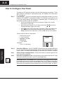
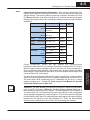
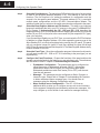
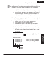
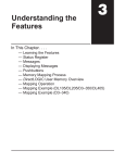
Configuring Your
Operator Panel
In This Chapter. . . .
— Preparing for Configuration
— How to Configure Your Panel
4
4–2
Configuring Your Operator Panel
Preparing for Configuration
Configuring Your
Operator Panel
Configuring
Your Panel
System Setup
Configuration
If you prepare and plan all information ahead of time, your use of the OP–WINEDIT
configuration software will be very successful. Below are a few important items to
perform while programming your application.
S Prepare personal computer and ensure proper installation of the
OP–WINEDIT configuration software.
S Examine and understand your operator interface requirements. Determine
which OP–panel(s) are needed, and if a single panel or multiple panel
configuration is to be used.
S Know your PLC product and available resources, such as programming tools,
CPU capabilities, unused or user memory for base register assignment (128
consecutive bits/panel)
S Verify type of communications port, as well as which protocol will be used.
Determine the CPU link(s) available for connecting an OP–panel
(RS–232/RS–422, baud rate, parity, stop bit).
S Think about how the Lamps, Pushbuttons, LEDs, and messages will be
assigned in your Operator panel(s) with respect to your machine or process.
To prepare your application, use the Application Worksheets which are provided in
the Appendix A of this manual. The example worksheets will help you understand
how the OP–1510 Kiln Demo program is configured. The blank worksheets can be
used in planning, implementing, and using your OP–1500 and/or OP–1510 units.
OPEditor Software The OP–1500 and OP–1510 are configured with software running on a personal
computer. This software is available through PLCDirect, and referred to as the
OPEditor configuration software (part number OP–WINEDIT). The OPEditor is used
to download your configuration before connecting the OP–1500 or OP–1510 unit(s)
and communicating to a PLC or OP–9001 Communication Master.
Configuring Your Operator Panel
More about
the OPEditor
OPEditor
Documentation
4–3
TIP: You may design and configure your Operator Panel configuration(s) offline and
save them to disk. The programs may then be downloaded to the OP–panel(s).
Appendix A “Application Worksheet” should be used to help plan your configurations
and programming process for each panel.
System
Requirements
Configuring Your
Operator Panel
The OPEditor configuration software allows you to configure OP–panel
applications, as well as download (write to panel) and upload (read from panel) the
configurations. Use this software to configure your communication link(s), select
pushbutton control, and enter operator display messages. The newer and most
recommended software is the OP–WINEDIT package. This windows software may
be ordered from PLCDirect using part number OP–WINEDIT.
For the OP–WINEDIT software (e.g. version 1.01 or greater) configuration Help
windows are provided for performing all necessary configuration tasks. Should you
have problems understanding how to program your panel, refer to these built–in On
Line Help windows. To call the Help windows, point and click on the Help menu and
choose Using help, or click on the [?] ICON located near the top of the main
configuration window.
The OP–WINEDIT software, must have the following minimum PC configuration:
S IBM 386 (or better) compatible computer
S VGA or SVGA video board and color monitor
S 1 meg of free hard drive space
S 1 meg of RAM memory
S Windows 3.1 or higher (OP–WINEDIT)
Configuring Your
Operator Panel
4–4
Configuring Your Operator Panel
How to Configure Your Panel
System Setup
Step 1
To prepare an OP–panel for operator use, the following steps are required . These
steps should be followed for implementing either the OptiMate OP–1500 and/or
OP–1510 panels.
Load OPEditor – If you are not already using the configuration software, you must
install the OP–WINEDIT configuration software. The software is provided on one
3–1/2” high density diskette and includes an installation guide. The following is a
description on how to install OP–WINEDIT.
S Place the installation disk into your computer’s floppy drive (usually
either drive A or drive B).
S Open Microsoft Windows (3.0 or above) and select File/Run from the
Program Manager (upper–left corner).
S Select Run, and you will see a pop–up window. Type in the path for the
drive in which you have placed the setup disk and designate the file
setup. Here we have used drive A. Click on OK when you are finished.
Personal Computer Minimum Requirements:
Configuring
Your Panel
3 IBM type 386 or above
3 1 meg of hard drive
3 Windows 3.1 or later
3 Windows 95
3 1 meg of RAM
Disk Media:
3 One 3–1/2” high density
Configuring Your
Operator Panel
Step 2
Step 3
Step 4
Direct
LOGIC
PLC
Select the COM ports – Your OP–WINEDIT software requires you select which port
is to be used for upload and downloading. Ensure serial port selected is not being
used by other PC software while attempting to operate the OP–WINEDIT software.
Choose Single or Multiple Panel – Decide the number of operator panels to be
used within your application.
Select the Configuration Link – Here is where you will need to select the PLC type
and model which will be used in your OP–panel application.
DirectLOGIC PLCs : Some DirectLOGIC CPUs feature a secondary communication
port which may be used to connect the OptiMate units. Your OPEditor configuration
must match the PLC port setups, such as address, baud rate, stop bits, and parity.
Also ensure the secondary communications port is set for HEX mode, not ASCII.
Configuring Your Operator Panel
Step 5
4–5
Complete the Communications Information – After you have selected the PLC
type you must define the remaining protocol items , such as the baud rate, parity and
stop bit settings. The following table provides the necessary information for most
PLCDirect controllers. In the case of using other PLC product and family, you should
reference the proper product User manual(s) to determine the port communications
capabilities.
PLC Model
Port/Baud Rates
DL105/230/240
9600
Top
Parity
Odd
1
Bottom Bottom (DL240 only)
9600/19.2k
DL250
Top 9600
Stop
Bit
Odd/None
Odd/None
DL330
DCU only 4800/9600/19.2k
Odd/None
1
DL340
Bottom &Top 4800/9600/19.2k
Odd/None
1
DL350
Top 9600
Odd
Bottom 4800/9600/19.2K
DL430/440
Top Top
9600
Bottom 9600/19.2k
DL450
DB15 9600
1
Odd/None
Odd
Odd/None
1
Odd
DB25 9600/19.2k
Odd/None
RJ12 9600/19.2k
Odd/None
1
PLC
OTHER PLCs : For Allen–Bradley, you will need to connect to Channel 0 (bottom serial
port), using DF1 full duplex. Additionally, the Allen–Bradley software allows you to
set the bottom port to a unique PLC address. The software default is PLC Address 1.
You must select CRC error detection and ensure the address on the configuration
screen matches the address you have assigned. This port must also be configured
for either 4800 or 9600 baud. No other baud rates are supported for communicating
between the OP–panels and an Allen–Bradley PLC. Since the Allen–Bradley
software uses a default baud rate of 1200, you must change the settings.
Configuring Your
Operator Panel
During configuration, ensure that your address and communications
parameters match the PLC port settings. There will be a selection for PLC timeout.
When the panel sends a message to the PLC and does not receive a response or
does not understand the response, it will wait the time–out period before resending
the message. A communication failure after 12 seconds initiates the message “Host
Communication Fail” on the panel.
You also have several ports which can be used to connect your communications
cable. Some of these ports have fixed PLC address assignments, and some do not.
The ports which allow configuring the PLC addresses can be set to a unique
address, ranging from 1 through 90. Refer to your User Manual for specific
information on the ports of your PLC.
OTHER
Configuring Your
Operator Panel
1
Bottom 9600/19.2K
4–6
Configuring Your Operator Panel
Step 6
System Setup
Step 7
Step 8
Configuring Your
Operator Panel
Configuring
Your Panel
Step 9
Select the Panel Address – The panel has a DIP switch on the rear of the unit which
is used to set the panel address (between 0–31). This address is used for two
functions. The first function is for setting the address for configuration and the
second is for the specific panel address. This panel address (0–31) is used with
multiple panel configurations and the OP–9001 Communications Master. The
address number that you select on the switch must also be configured to the panel.
Select the Base Register Address and File Number – This step is very important
because it establishes the link in your PLC memory to the panel. For DirectLOGIC
PLCs Chapter 3 Understanding the OP- 1500 and OP- 1510 describes the
mapping process. Once you are familiar with the mapping process and you know the
memory in your PLC to use (refer to the user manual for your respective PLC type),
enter your selection.
If you choose Allen–Bradley as your PLC Type, you must enter the PLC File Number
in addition to a Base Register Address. You must expand the memory map in the
Allen–Bradley PLC to include all registers being used by the OP–panel. The panel
will only recognize integer file types N7 and user–defined file types N9 through
N255. Enter the number only and not the prefix N. The Base Register Address is any
number between 0 and 255.
Select the Panel Type – Since the configuration program is the same for all panels,
you will need to select OP- 1500 or OPć1510 according to the panel type you are
implementing.
Configure the Panel Functions – Prepare the functions of the panel and how the
operator control shall work for the features you are selecting to use. These features
are discussed in detail in Chapter 3 Understanding the Features.
S Pushbutton Configuration – The pushbuttons can be configured as
either Momentary or Maintained (alternate ON/OFF). Momentary
pushbuttons remain ON as long as you are pressing them while
Maintained pushbuttons retain their status (ON or OFF) until the next
time they are pressed.
S Message – The messages may be configured as Static, Dynamic or
Interactive type. Please refer to Chapter 3 Understanding the Features
to better understand these message types. You should enter all
messages using the Message Configuration window.
S Menu and Sub–menu Configuration – The OP–1510 has an
additional ability to allow you to configure a menu sub–menu hierarchy
for the purpose of displaying and interacting with screen messages. You
may configure up to four levels of sub–menus for message hierarchy.
Configuring Your Operator Panel
4–7
Step 10
Configuring your Menu – In order to successfully use the Menu and Sub–menu
(OP–1510 features refer to the “Menu and Sub–menu” section of Chapter 3 in this manual. The
Only)
OP–WINEDIT configuration software allows definition of the following terms.
S
S
Level Number – defines the menu/sub–menu for each item number and
how it is represented (up to four levels of sub–menu nesting permitted).
Function number – is assigned to menu messages in which interactive
message type is required. The function numbers must be unique for
each menu message and should follow sequential order. This allows for
the function number to be evaluated within register m+2, when a menu
item is selected.
1.
2.
3.
4.
Select the existing or new OP–1510 panel configuration file.
Access the “Menu configuration” window or screen.
Begin entering the hierarchy at item 1 for the main menu/function.
Enter text message and menu control characteristics for each item, such as
level number, function number, etc..
5. Menu structures may be entered with sub–menu messages. You may nest
up to four levels of sub-menus.
6. For Functions, configure the function number within the message entry
box. Function numbers should be entered in sequential order (1, 2, 3, etc..).
Configuring Your
Operator Panel
While configuring a menu message system the menu items are assigned in
sequential order 1 thru 160. Each item within the menu/sub–menu hierarchy require
parameterizing in the following steps.
Your Menu Plan
Function1 Arrow Up/Down Hopper #
Function2 Enter Kiln Speed
Temperature Control
Setpoint Zone1 Temp.
Setpoint Zone2 Temp.
Setpoint Zone3 Temp.
Heating Method
Etc..
Level One
Level Two
Level Three
Level Four
Function3 Enter Zone1 Temperature
Function4 Enter Zone2 Temperature
Function5 Enter Zone3 Temperature
Configuring Your
Operator Panel
Raw Meal Control
Hopper Selection
Kiln Speed
4–8
Configuring Your Operator Panel
Step 11
Save and Download – Once you have completed your configuration, you can save
it to disk and/or write directly to the panel. If saving to the panel, verify that the DIP
switch is set to 31 (refer to Preparing the Panel for Configuration Chapter 2) to
download the configuration. When downloading to OP-panels which have already
been configured, you must first clear the message list before loading the new
configuration. This will ensure the old messages which are configured do not remain
within the OP-panel’s memory.
NOTE: After your configuration has been properly downloaded, you will need to reset
Configuring Your
Operator Panel
Configuring
Your Panel
System Setup
the DIP switch to the appropriate panel address and power cycle the panel. This can
be accomplished by simply removing and reinstalling the power source.