1
Contents
1
Introduction
1
2
2.1
Getting Started
Achieving the Best Performance
2
2
3
3.1
3.2
3.3
Overview
Shielded Twisted Pair (STP) / Unshielded Twisted Pair (UTP)
Defining EDID
Defining the TP-410 UXGA-Audio-RS-232 Line Transmitter / DA
3
4
4
4
4
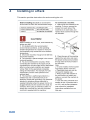
Installing in a Rack
8
5
5.1
5.2
5.3
5.4
5.5
Connecting the TP-410
Connecting the TP-410
Connecting to the TP-410 via an RS-232 Connection
Connecting to the TP-410 via an RS-485 Connection
Connecting to the TP-410 via the ETHERNET
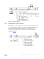
Connecting Several TP-410 Units
9
9
11
11
12
14
6
6.1
Configuration and Distribution of Control Data
The Local Mode
15
15
7
7.1
7.2
7.3
The SETUP DIP-switches
Setting the Machine Number
Setting the RS-232/RS-485 Baud Rate DIP-switches
Setting the RS-485 Bus Termination
19
19
20
21
8
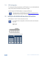
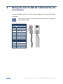
Wiring the CAT 5 LINE IN / LINE OUT RJ-45 Connectors
22
9
Acquiring the EDID
23
10
Flash Memory Upgrade
24
11
11.1
12
Technical Specifications
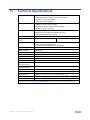
Communication Parameters
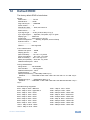
Default EDID
25
26
27
13
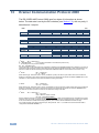
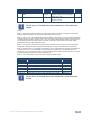
Kramer Communication Protocol 2000
28
Figures
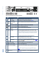
Figure 1: TP-410 UXGA-Audio-RS-232 Line Transmitter / DA Front Panel
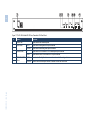
Figure 2: TP-410 UXGA-Audio-RS-232 Line Transmitter / DA Rear Panel
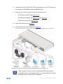
Figure 3: Connecting the TP-410, UXGA-Audio-RS-232 Line Transmitter / DA
Figure 4: RS-232 Pinout
Figure 5: Local Area Connection Properties Window
Figure 6: Internet Protocol (TCP/IP) Properties Window
Figure 7: Connecting Multiple TP-410 Units
Figure 8: Local Control via RS-232
Figure 9: Control via the Ethernet
Figure 10: RS-232 Remote Control
Figure 11: Connecting Multiple TP-410 Units via RS-485
Figure 12: The Address # DIP-switches
Figure 13: TP-410 Baud Rate DIP-switches
Figure 14: TP-410 DIP-switch RS-485 Termination
Figure 15: CAT 5 PINOUT
5
6
10
11
13
13
14
16
16
17
18
19
20
21
22
TP-410 – Contents
i
U
U
U
U
U
U
U
U
U
U
U
U
U
U
U
U
U
U
U
U
U
U
U
U
U
U
U
U
U
U