1
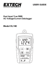
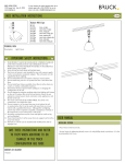
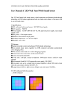
Lederaa LED Lighting Web: www.Lederaa.com Contact: [email protected] RSC16x series User Manual RS485 Control Perfect Solution V2.1 2005/5/30 INDEX 1 2 3 4 5 6 Products Introduction ..................................................................2 1.1 RSC165 Introduction ...........................................................3 1.2 RSC166 Introduction ...........................................................4 1.3 RSC167 Introduction ...........................................................5 Product Specification ..................................................................6 2.1 RSC165 Specification ..........................................................6 2.2 RSC166 Specification ..........................................................7 2.3 RSC167 Specification ..........................................................8 Install Consideration .................................................................9 Hardware Installation ................................................................ 10 4.1 RSC165 Install Guide......................................................... 10 4.1.1 Front Cover Details ..................................................... 10 4.1.2 Rear Cover Details ...................................................... 11 4.1.3 RSC165 Hardware Install Steps ................................... 12 4.2 RSC166 Install Guide......................................................... 13 4.2.1 Appearance Details ...................................................... 13 4.2.2 RSC166 Hardware Install Steps ................................... 14 4.3 RSC167 Install Guide......................................................... 15 4.3.1 Appearance Details ...................................................... 15 Operation Guide........................................................................ 16 5.1 Swith On/Off Multi Color lamp .......................................... 16 5.2 How to Choose a Program.................................................. 16 5.3 How to Set the Program to Hot-key.................................... 17 5.4 Remote Control .................................................................. 18 Advance Operation ................................................................... 19 6.1 Set the ID of LED by RSC165 ........................................... 20 6.2 Set the Maximum ID Number ............................................ 21 6.3 Set the Extensible ID of RSC165 (X-Y coordinate) ............... 22 1 Chapter 1 Products Introduction Lederaa offers series RSC16x as the best solution for the networking LED lamp. By the RS485 interface, you can unite all the net LED lamps to proceed the programs like marquee, flash etc. Controlling the system of the net LED lamps to do the various functions, you can also use relative software to edit action and pattern with individual PC. The following are the main functions of series RSC16x. RSC165 (RS485 Controller) RSC165 is a combo-controller of RS485, once you purchase the LED lamp which has RS485 function, you can make all the LED lamps do the synchronous change by RSC165. RSC165 has got 20 different modes, such as marquee, random color, gradient… etc. RSC165 is extensible for update firmware, more than that; The mode program can be rewrite as requests. To control more LED lamps, you can go with RSC167 to increase the signals as the driver of RSC165 is not capable enough. RSC166 (USB->RS485 Converter) RSC166 is an USB->RS485 converter with USB port (1.1/2.0), which can control the LED lamps by transforming the signals to RS485. With LEDERAA particular LED lamp control program, clients can do whatever they want with the lamps by software. To control more LED lamps, you can go with RSC167 to increase the signals as the driver of RSC166 is over-drive. While applying to a large system (commercial-board), you can string up RSC165 by X-Y coordinate to have advance control of lamps. * see figures from Chapter 1-2. RSC167 (RS485 Repeater) RSC167 is the function of RS485 signal that mainly extend the drivers of RSC165/RSC166, and make more lamps work. Each RSC167 can string up to 32 LED lamps, or 32 RSC167 to enlarge the number of lamps. 2 1-1. RSC165 Introduction Products Features: 1. Six buttons, LCD screen, intelligent and friendly human computer interface 2. 20 modes to choose from. 3. You can easily set up to 5 functions that correspond to hot keys (F1~F5). 4. Low power, for both AC and DC, wide-ranging of voltage, easy to install. 5. Distribute by terminals plug, you can simply put it on the wall. Apply condition: 1. Synchronous control under small loop (<126LED lamps) 2. Multi-functions needed, such as marquee, flash, gradient…etc. 3. Operate individually without PC. System form: AC 110/220V 轉 DC12V Adaptor MR16 ID 1 MR16 ID 10 MR16 ID 32 MR16 ID 33 MR16 ID 43 MR16 ID 64 MR16 ID 65 MR16 ID 75 MR16 ID 96 diagram1-1-1. Apply with RSC165 1. 2. 3. This diagram indicates that the LED lamp will still require the power supply, since the interface of RS485 can’t provide it. Please beware of that when using. RSC165 will also require power supply and 110V/220V to 8~20Vdc transformer is recommended. The diagram above is optional for “-96”, which contains 3 sets of RS485 ports, therefore, it can string up to 96 lamps. You won’t need this option if the number of lamps is less than 32. 3 1-2. RSC166 Introduction Products Features: 1. USB interface, consist 1.1/2.0. 2. With Lederaa particular LED lamp control program LEDwizard, clients can do whatever they want with the lamps. 3. Direct output USB to RS485. 4. Low power, USB power supply. 5. Separating terminal design, distribution trouble-free. Apply condition: 1. Lamps variation control by PC connection. 2. Large system or number of lamps (>500), extensible with 165 and RSC167. 3. Controlling the lamps variation by writing a program. System form: diagram1-2-1. Apply with RSC166 diagram1-2-2. RSC166 strings up RSC165 This diagram indicates that the LED lamp will still require the power supply, since the interface of RS485 can’t provide it. Please beware of that when using 4 1-3. RSC167 Introduction Products Features: 1. Offer the function of fan-out to increase the control-ability of RSC165/166. 2. Low power, for both AC and DC, wide-ranging of voltage, easy to install. 3. Separating terminal design, distribution trouble-free. Apply condition: 1. When RSC165 is needed to control more than 32 lamps, it can string up RSC167 to raise the signal. 2. When RSC166 is needed to control more than 32 lamps, it can string up RSC167 to raise the signal. 3. To lengthen the distance by string up RSC167 when it’s over 300m. System form: Diagram 1-3-1. RSC166 strings up RSC167 Diagram 1-3-1. RSC165 strings up RSC167 This diagram indicates that the LED lamp will still require the power supply, since the interface of RS485 can’t provide it. Please beware of that 5 when using Chapter 2 Product Specification 2-1. RSC165 Specification parameter value unit remarks Function specification User interface Input interface Output interface Numbers of driver device Total wiring distance 6 Keys + 8*2 Text LCD , IrDA Remote Control Half-Duplex RS485 port(Default) * 1 Half-Duplex RS485 port * 1 >Lamp * 32 or RSC165 * 32 >300 String function Yes Key-in program >= 8 sets meter Can be accepted by RSC165 or other RSC165 Can be added by update program Power specification Standard input voltage Maximum input voltage Input current Power consumption 9~18Vdc or 8~15Vac V 24 Vdc or 20 Vac V <100mA < 1W mA W It’ll burn up if the input voltage is larger than maximum. Environment specification Working temp. Store temp. Working humidity Size Weight 0~50 -20~60 o 10~90 % 126.3 * 76.2 * 40 <0.5 mm Kg Optional -96 Half-Duplex RS485 port * 3 (Total Fan out = 96 device) 6 o C C Condensing condition excluded 2-2. RSC166 Specification parameter value unit remarks Function specification Input interface Output interface Numbers of driver device Total wiring distance USB 1.1 / 2.0 Half-Duplex RS485 port * 1 Mini-USB plug > Lamp * 32 or RSC165 * 32 >300 meter 5Vdc V Power specification Standard input voltage Input current Power consumption <100mA mA < 0.5W W 0~50 -20~60 o 10~90 % USB power supply Environment specification Working temp. Store temp. Working humidity Size Weight 88 * 43.8 * 26.6 <0.5 7 o C C mm Kg Condensing condition excluded 2-1. RSC167 Specification parameter value unit remarks Function specification Input interface Output interface Numbers of driver device Total wiring distance Half-Duplex RS485 port * 1 Half-Duplex RS485 port * 1 > Lamp * 32 or RSC165 * 32 >300 meter Power Specification Standard input voltage Maximum input voltage Input current Power consumption 7~12Vdc or 7~10Vac V 15 Vdc or 12 Vac V <100mA mA < 1W W It’ll burn up if the input voltage is larger than maximum. Environment Specification Working temp. Store temp. Working humidity Size Weight 0~50 -20~60 o 10~90 % 88 * 43.8 * 26.6 <0.5 8 o C C mm Kg Condensing excluded condition Chapter 3 Installation Consideration The product of this series has the precise circuits which are controlled by micro processor. For the safety concern, please read the following before using to avoid the risk of damage. 1. The product is used regularly (non-switch off condition), therefore; there’s no power switch design for it. Please turn the power off when first time distributing the wire for safety reason. 2. Please do following the specification above to supply the power to our products. Be sure that the voltage is between the correct values, otherwise it might burn up when the voltage is too high, and it might not work properly when the voltage is too low. 3. RSC165 and RSC167series are for both AC and DC, please feel free when using! 1. To avoid the man-made static caused damage, please do not touch any IC component when pick up RSC165. 2. RS485 interface can drive many devices, is noise resistent, and can be used for long distance data transmission, but there’s still restriction of Fan-Out(drive) and total distance. To avoid the controlling unstable situation, please do follow the specification when using. 1. If there’s any operating problem, please read through the fault clearing from the appendix. Follow the steps to solve the problem. 2. Please contact with our stuff or technicians if your problem solution is not written in the appendix. Thank you for purchase our products. 9 Chapter 4 Hardware Installation 4-1. RSC165 Install guide 4-1-1. Front Cover Details Number 1 Name F1 Use Normal mode Hot key of first mode System mode Press and hold for 2sec.to Remarks enter the system mode 2 F2 Normal mode Hot key of second mode System mode Exit the system mode (without any saving) 3 4 F3 F4 5 F5 6 PWR 7 LCD window 8 POWER 9 Infrared window Normal mode Hot key of third mode System mode Select upwards Normal mode Hot key of fourth mode System mode Select downwards Normal mode Hot key of fifth mode System mode Enter button On/Off control of all the LED lamps under the RSC165 process message display Green light ON Indicate all the lamps OFF Easy to find OFF Indicate all the lamps ON in the dark Receiving the infrared signal by LED lamp remote control 10 4-1-2. Rear Cover Details Number 1 2 Name Power input 5 1st RS485output,can drive 32 Please beware of the terminal devices polar nd 2 RS485 output 2 RS485 output, can drive 32 Please beware of the terminal devices polar rd 3 RS485output 3 RS485 output, can drive 32 Please beware of the terminal devices polar Accepting the RS485 input internal Please beware of the which controlled by RSC166 or polar RS485 input terminal other RSC165 download Please do not Firmware upgrade connector 7 8~20V (AC/DC sharing) Firmware 6 Remarks 1st RS485 output rd 4 Supply the power to RSC165 terminal nd 3 Use Upgrade mode switch upgrade it by yourself (staff only) Please do not Firmware upgrade switch on/off upgrade it by yourself (staff only) * Please beware of the polar of RS485 connecter. * It’s recommended not to upgrade the function of firmware by your own, since RSC165 might not work properly. Please ask technicians for help 11 4-1-3. RSC165 Hardware Installation Steps 1. Confirm the power supply of RSC165 is cut off first 2. Lock both power and RS485 signal wires to the terminal board that corresponds (refers to the details above) 3. Turn on the power 4. Make sure the screen is working normal like pictures below 5. Hold Press for 2 seconds; make sure all the LED lamps can be turn off. again to confirm that all the lamps can be turn on. 6. Ready for use (refers to chapter 5) 12 4-2. RSC166 Install Guide 4-2-1. Appearance Details Number 1 2 Name RS485 output Use Output terminal of RS485 interface terminal Remarks Please beware of the polar USB input USB plug, USB interface for PC terminal connecting * Please beware of the polar of RS485 connecter 13 4-2-2. RSC166 Hardware Install Steps 1. A software driver will be needed when connecting RSC166 the first time. The software can be downloaded on-line. 2. Take off the separate terminal board, and lock the RS485 signal wire of the LED lamps to the terminal board that corresponds. 3. Put the terminal board back to RSC166 4. Start the LED control software to make sure that LED lamps can be controlled 14 4-3. RSC167 Install Guide 4-3-1. Appearance Details Number 1 2 3 Name Power input Use Power supply for RSC167 terminal Remarks 8~12V (AC/DC sharing) RS485 output Output terminal of RS485 interface, Please beware of terminal strings up LED lamps the polar RS485 input Input terminal of RS485 interface, Please beware of terminal receiving the signal from RS485 the polar Please beware of the polar of RS485 connecter 15 Chapter 5 Operation Guide 5-1. Switch On/Off Multi Color lamp Power on All the LED lamps are off at the time Hold PWR for 2 sec. Press PWR button Power off All the LED lamps are on at the time 5-2. How to Choose a Program Press : execute the program assigned by 1 st hotkey Press : execute the program assigned by 2 nd hotkey Press : execute the program assigned by 3 rd hotkey Press : execute the program assigned by 4 th hotkey Press : execute the program assigned by 5 th hotkey F=n, means press Fn button P=m, show the executing key-in program “1sFlash” shows the name of the program (Refers to the next chapter) 16 5-3. How to Set the Program to Hot-key 1. Select the hot-key you want to set your program to, then press and hold the button Hold 2sec : Set the program assigned by 1st hotkey Hold 2sec : Set the program assigned by 2nd hotkey Hold 2sec : Set the program assigned by 3rd hotkey Hold 2sec : Set the program assigned by 4th hotkey Hold 2sec : Set the program assigned by 5th hotkey 2. Press up and down(F3,F4) to select the function(all the lamps will do the action assigned by the selected program) It’ll flash when entering the hotkey function setting 3. Press ENT(F5) to confirm the program to the hotkey Press ENT to finish the setting 17 5-4. Remote Control (IRC160) RSC165 has the infrared window which can receive the signal from IRC160, then control all the LED lamps of RSC165 Aim the remote control to the RSC165 receive window (figure5-4-1), and press the function required, all the LED lamps will change to the particular color (or mode) at the same time Infrared receive window Figure 5-4-1. Use IRC160 to control the lamps through RSC165 18 Chapter 6 Advance Operation 6-1. Use RSC165 to set the ID of LED lamps 1. Tools required: a. RSC165 * 1 b. IRC160 * 1 (remote control for LED lamps) 2. Function explanation : Each lamp ID can be set when it has the RS485 function. The correct ID is needed to operate some key-in function (e.g. marquee), this section will explain how to use RSC165+IRC160 to set the ID of LED lamps. The fixed ID is “1” as the LED produced, (vary only if request) 3. Setting Explanation: a. It’s important to remember that aim only the LED lamps you want when you’re setting the ID of RSC165 by the remote control. Otherwise, all the lamps that string together will be set as one ID. The ID can only be set when the power of LED lamps and RSC165 is on. b. Turn on the power of LED lamps and RSC165; aim IRC160 to the infrared window of RSC165. Press button on IRC160, then the LED lamps will flash to enter the ID setting mode. If you want to quit at this stage just press button. c. When the power of RSC165 is on, hold for 2sec. to enter the option “Set485Id” (figure below). Press up and down to select the ID and press ; LED will stop flashing to finish the setting. 19 6-2. Set the Maximum ID Number 1. Function Explanation: Under some functions (e.g. marquee), RSC165 must know how many ID are in the loop to make sure the function can run correctly to the last lamp then jump to the next mode. This part of the chapter is mainly narrating how to set the maximum ID number. 1. 2. The fixed ID number is “16” as RSC165 produced. The marquee function might not run it to the last lamp or stocked for a while to get to the next mode when the maximum ID is incorrect. The value is the maximum value of LED lamp ID which connected by RSC165, not the number of lamps. (The maximum lamp number might be different from the maximum ID for special action sometimes) Please beware of it! 2. Setting Explanation: a. Hold 2sec. to enter the setting mode Hold it for 2sec. b. Press twice to enter the maximum ID setting mode (StMaxAdr), like figure below c. press to select the number, then press finish the setting 20 to 6-3. Set the Extensible ID of RSC165 (X-Y coordinate) 1. Function explanation Under a larger system (e.g. LED commercial-board), RSC165 must set the ID coordinate (it’ll be the ID of RSC165 itself, has nothing to do with the ID of LED lamps) Once the X-Y coordinates are set, the lamps that connected to RSC165 will be placed as one group. Combining RSC167 to increase the signal, then one group can connect 126 lamps. The limit of X-Y ID coordinate is X=126, Y=126, therefore in this kind of ID setting, the maximum number of lamps is : 126(X coordinate) * 126(Y coordinate) * 126(lamp ID) = 2, 000, 0376 This part of the chapter is narrating how to set the X-Y coordinate ID X = 1, Y = 1 fixed coordinates as RSC165 produced If the value is incorrect, the LED action will be mistaken under a big system. If it’s only RSC165, it won’t have any effect. 2. Setting Explanation: 1. Hold for 2sec. to enter the setting screen Hold it for 2sec. 21 2. Press 3 times to enter the X coordinate setting screen(figure below), and press up or down to select the ID of X coordinate needed 3. Press again to enter the Y coordinate setting screen(figure below), and press up or down to select the ID of X coordinate needed 4. 5. press to finish setting 22