1
C P / M
1 . 4
U S E R
G U I D E
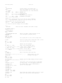
TABLE OF CONTENTS
INTRODUCTION
1.1 CP/M Organization
1.2 Operation of Transient Programs
1.3 Operating System Facilities
1
1
1
3
2. BASIC I/0 FACILITIES
2.1 Direct and Buffered I/0
2.2 A Simple Example
4
5
5
3. DISK I/0 FACILITIES
3.1 File System Organization
3.2 File Control Block Format
3.3 Disk Access Primitives
3.4 Random Access
9
9
10
12
18
4. SYSTEM GENERATION
18
4.1 Initializing CP/M from an Existing Diskette 19
5. CP/M ENTRY POINT SUMMARY
6. ADDRESS ASSIGNMENTS
7. SAMPLE PROGRAMS
20
22
23
CP/M INTERFACE GUIDE
1.
INTRODUCTION
This manual describes the CP/M system organization including
the structure of memory, as well as system entry points. The
intention here is to provide the necessary information required
to write programs which operate under CP/M, and which use the
peripheral and disk I/0 facilities of the system.
1.1
CP/M Organization
CP/M is logically divided into four parts:
BIOS - the basic I/0 system for serial peripheral control
BDOS - the basic disk operating system primitives
CCP - the console command processor
TPA - the transient program area
The BIOS and BDOS are combined into a single program with a common entry point and referred to as the FDOS. The CCP is a distinct program which uses the FDOS to provide a human-oriented
interface to the information which is cataloged on the diskette.
The TPA is an area of memory (i.e, the portion which is not used
by the FDOS and CCP) where various non-resident operating system
commands are executed. User programs also execute in the TPA.
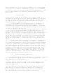
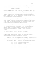
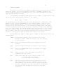
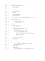
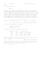
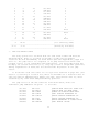
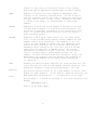
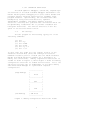
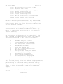
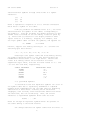
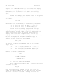
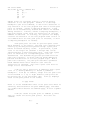
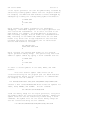
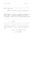
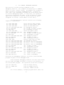
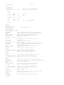
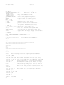
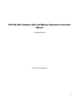
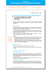
The organization of memory in a standard CP/M system is shown in
Figure 1.
The lower portion of memory is reserved for system information
(which is detailed in later sections), including user defined interrupt locations. The portion between tbase and cbase is reserved
for the transient operating system commands, while the portion
above cbase contains the resident CCP and FDOS. The last three
locations of memory contain a jump instruction to the FDOS entry
point which provides access to system functions.
1.2
Operation of Transient Programs
Transient programs (system functions and user-defined programs)
are loaded into the TPA and executed as follows. The operator
communicates with the CCP by typing command lines following each
prompt character. Each command line takes one of the forms:
<command>
<command> <filename>
<command> <cfilename>.<filetype>
2
Figure 1.
CP/M Memory Organization
fbase:
cbase:
tbase:
boot:
entry:
Note:
+-------------------+
|
|
|
FDOS
|
+-------------------+
|
|
|
CCP
|
+-------------------+
|
|
|
|
|
TPA
|
|
|
|
|
+-------------------+
| System Parameters |
+-+-+-+-+-+-+-+-+
|
| | | | | | | | |
|
+-+-+-+-+-+-+-+-+---+
^ ^
| |-- address field of jump is fbase
|
the principal entry point,to FDOS is at location 0005
which contains a JMP to fbase. The address field at
location 0006 can be used to determine the size of
available memory, assuming the CCP is being overlayed.
The exact addresses for boot, tbase, cbase, fbase,
and entry vary with the CP/M version (see
Section 6. for version correspondence).
3
Where <command> is either a built-in command (e.g., DIR or TYPE),
or the name of a transient command or program. If the <command>
is a built-in function of CP/M, it is executed immediately; otherwise the CCP searches the currently addressed disk for a file
by the name
<command>.COM
If the file is found, it is assumed to be a memory image of a
program which executes in the TPA, and thus implicitly originates
at tbase in memory (see the CP/M LOAD command). The CCP loads
the COM file from the diskette into memory starting at tbase,
and extending up to address cbase.
If the <command> is followed by either a <filename> or
<filename>.<filetype>, then the CCP prepares a file controlblock (FCB) in the system information area of memory. This FCB
is in the form required to access the file through the FDOS, and
is given in detail in Section 3.2.
The program then executes, perhaps using the I/0 facilities
of the FDOS. If the program uses no FDOS facilities, then the
entire remaining memory area is available for data used by the
program. If the FDOS is to remain in memory, then the transient
program can use only up to location fbase as data.* In any case,
if the CCP area is used by the transient, the entire CP/M system
must be reloaded upon the transient's completion. This system
reload is accomplished by a direct branch to location "boot" in
memory.
The transient uses the CP/M I/0 facilities to communicate
with the operator's console and peripheral devices, including
the floppy disk subsystem. The I/0 system is accessed by passing
a "function number" and an "information address" to CP/M through
the address marked "entry" in Figure 1. In the case of a disk
read, for example, the transient program sends the number corresponding to a disk read, along with the address of an FCB, and
CP/M performs the operation, returning with either a disk read
complete indication or an error number indicating that the disk
operation was unsuccessful. The function numbers and error indicators are given in detail in Section 3.3.
1.3
Operating System Facilities
CP/M facilities which are available to transients are divided
into two categories: BIOS operations, and BDOS primitives. The
BIOS operations are listed first:**
* Address "entry" contains a jump to the lowest address in the
FDOS, and thus "entry+1" contains the first FDOS address which
cannot be overlayed.
**The device support (exclusive of the disk subsystem) corresponds exactly to Intel's peripheral definition, including I/0
port assignment and status byte format (see the Intel manual
which discusses the Intellec MDS hardware environment).
4
Read Console Character
Write Console Character
Read Reader Character
Write Punch Character
Write List Device Character
Set I/0 Status
Interrogate Device Status
Print Console Buffer
Read Console Buffer
Interrogate Console Status
The exact details of BIOS access are given in Section 2.
The BDOS primitives include the following operations:
Disk System Reset
Drive Select
File Creation
File Open
File Close
Directory Search
File Delete
File Rename
Read Record
Write Record
Interrogate Available Disks
Interrogate Selected Disk
Set DMA Address
The details of BDOS access are given in Section 3.
2.
BASIC I/0 FACILITIES
Access to common peripherals is accomplished by passing a
function number and information address to the BIOS. In general,
the function number is passed in Register C, while the information address is passed in Register pair D,E. Note that this
conforms to the PL/M conventions for parameter passing, and thus
the following PL/M procedure is sufficient to link to the BIOS
when a value is returned:
DECLARE ENTRY LITERALLY
MON2:
'0005H'; /* MONITOR ENTRY */
PROCEDURE (FUNC, INFO) BYTE;
DECLARE FUNC BYTE, INFO ADDRESS;
GO TO ENTRY;
END MON2;
5
or
MON1:
PROCEDURE (FUNC,INFO);
DECLARE FUNC BYTE, INFO ADDRESS;
GO TO ENTRY;
END MON1
if no returned value is expected.
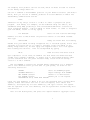
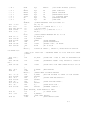
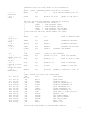
2.1 Direct and Buffered I/0.
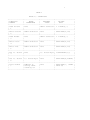
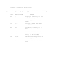
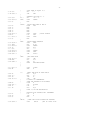
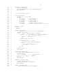
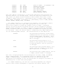
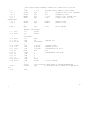
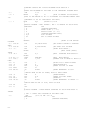
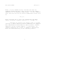
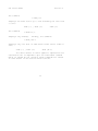
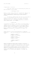
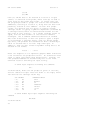
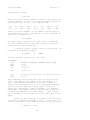
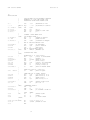
The BIOS entry points are given in Table I. in the case of
simple character I/0 to the console, the BIOS reads the console
device, and removes the parity bit. The character is echoed back
to the console, and tab characters (control-I) are expanded to
tab positions starting at column one and separated by eight character positions. The I/0 status byte takes the form shown in
Table I, and can be programmatically interrogated or changed.
The buffered read operation takes advantage of the CPM line editing facilities. That is, the program sends the address of a read
buffer whose first byte is the length of the buffer. The second
byte is initially empty, but is filled-in by CPM to the number
of characters read from the console after the operation (not
including the terminating carriage-return). The remaining positions are used to hold the characters read from the console. The
BIOS line editing functions which are performed during this operation are given below:
break
rubout
control-C
control-U
control-E
<cr>
-
line delete and transmit
delete last character typed, and echo
system rebout
delete entire line
return carriage, but do not transmit
buffer (physical carriage return)
- transmit buffer
The read routine also detects control character sequences other
than those shown above, and echos them with a preceding "^"
symbol. The print entry point allows an entire string of symbols
to be printed before returning from the BIOS. The string is
terminated by a "$" symbol.
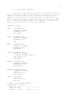
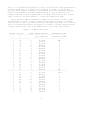
2.2 A Simple Example
As an example, consider the following PL/M procedures and
procedure calls which print a heading, and successively read
the console buffer. Each console buffer is then echoed back in
reverse order:
6
PRINTCHAR: PROCEDURE (B);
/* SEND THE ASCII CHARACTER B TO THE CONSOLE */
DECLARE B BYTE:
CALL MON1 (2, B)
END PRINTCHAR;
CRLF:
PROCEDURE;
/* SEND CARRIAGE-RETURN-LINE-FEED CHARACTERS */
CALL PRINTCHAR (ODH);
CALL PRINTCHAR (OAH);
END CRLF;
PRINT:
PROCEDURE (A);
/* PRINT THE BUFFER STARTING AT ADDRESS A */
DECLARE A ADDRESS;
CALL MON1(9,A);
END PRINT;
DECLARE RDBUFF (130) BYTE;
READ:
PROCEDURE;
/* READ CONSOLE CHARACTERS INTO 'RDBUFF' */
RDBUFF=128; /* FIRST BYTE SET TO BUFFER LENGTH */
CALL MON1(10,.RDBUFF);
END READ;
DECLARE I BYTE;
CALL CRLF;
CALL PRINT (.'TYPE INPUT LINES $');
DO WHILE 1; /* INFINITE LOOP-UNTIL CONTROL-C */
CALL CRLF; CALL PRINTCHAR ('*'); /* PROMPT WITH '*' */
CALL READ; I = RDBUFF(1);
DO WHILE (I:= I -1) <> 255;
CALL PRINTCHAR (RDBUFF(I+2));
END;
END;
The execution of this program might proceed as follows:
{ <cr> = carriage return }
TYPE INPUT LINES
*HELLO<cr>
OLLEH
*WALL WALLA WASH<cr>
HSAW ALLAW ALLAW
*mom wow<cr>
*wow mom
*^C
(system reboot)
7
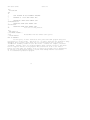
TABLE I
BASIC I/0 OPERATIONS
+----------------+-----------------+-----------------+---------------------+
| FUNCTION/
|
ENTRY
|
RETURNED
|
TYPICAL
|
| NUMBER
|
PARAMETERS
|
VALUE
|
CALL
|
+----------------+-----------------+-----------------+---------------------+
| Read Console
| None
| ASCII character | I = MON2(1,0)
|
| 1
|
|
|
|
+----------------+-----------------+-----------------+---------------------+
| Write Console | ASCII Character | None
| CALL MON1(2,'A')
|
| 2
|
|
|
|
+----------------+-----------------+-----------------+---------------------+
| Read Reader
| None
| ASCII character | I = MON2(3,0)
|
| 3
|
|
|
|
+----------------+-----------------+-----------------+---------------------+
| Write Punch
| ASCII Character | None
| CALL MON1(4,'B')
|
| 4
|
|
|
|
+----------------+-----------------+-----------------+---------------------+
| Write List
| ASCII Character | None
| CALL MON1(5,'C')
|
| 5
|
|
|
|
+----------------+-----------------+-----------------+---------------------+
| Get I/0 Status | None
| I/0 Status Byte | IOSTAT=M0N2(7,0)
|
| 7
|
|
|
|
+----------------+-----------------+-----------------+---------------------+
|
|
|
|
|
| Set I/0 Status | I/0 Status Byte | None
| CALL MON1(8,IOSTAT) |
| 8
|
|
|
|
+----------------+-----------------+-----------------+---------------------+
| Print Buffer
| Address of
| None
| CALL MON1(9, .PRINT |
| 9
| string termi|
| THIS $')
|
|
| nated by '$'
|
|
|
+----------------+-----------------+-----------------+---------------------+
8
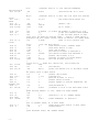
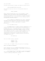
TABLE I (continued)
+----------------+-----------------+-----------------+---------------------+
| FUNCTION/
|
ENTRY
|
RETURNED
|
TYPICAL
|
| NUMBER
|
PARAMETERS
|
VALUE
|
CALL
|
+----------------+-----------------+-----------------+---------------------+
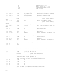
| Read Buffer
| Address of
| Read buffer is | CALL MON1(10,
|
| 10
| Read Buffer
|filled to maxi- | .RDBUFF);
|
|
|
|mum length with |
|
|
|
|console charac- |
|
|
|
(See Note 1) | ters
|
|
+----------------+-----------------+-----------------+---------------------+
| Interrogate
| None
| Byte value with | I = MON2(11,0)
|
| Console Ready |
| least signifi- |
|
|
|
| cant bit = 1
|
|
|
|
| (true) if con- |
|
|
|
| sole character |
|
|
|
| is ready
|
|
+----------------+-----------------+-----------------+---------------------+
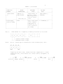
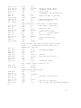
Note 1.
Read buffer is a sequence of memory locations of the form:
+---+---+----+----+----+--+----+---+---+---+
| m | k | c1 | c2 | c3 |
| ck |
|
|
|
+---+---+----+----+----+--+----+---+---+---+
^
^
|
|--current buffer length
+------Maximum buffer length
Note2
The I/0 status byte is defined as three fields A,B,C, and D
2b 2b 2b 2b
+---+---+---+---+
| A | B | C | D |
+---+---+---+---+
MSB
LSB
requiring two bits each, listed from most significant to least
significant bit, which define the current device assignment as
follows:
0 TTY
D = 1 CRT
Console 2 BATCH
3
-
0 TTY
C = 1 FAST READER
Reader 2
3
-
0 TTY
B
= 1 FAST PUNCH
Punch
2
3
-
0 TTY
A = 1 CRT
List 2 3 -
9
3.
DISK I/0 FACILITIES
The BDOS section of CP/M provides access to files stored on
diskettes. The discussion which follows gives the overall file
organization, along with file access mechanisms.
3.1 File organization
CP/M implements a named file structure on each diskette, providing a logical organization which allows any particular file to
contain any number of records, from completely empty, to the full
capacity of a diskette. Each diskette is logically distinct,
with a complete operating system, disk directory, and file data
area. The disk file names are in two parts: the <filename>
which can be from one to eight alphanumeric characters, and the
<filetype> which consists of zero through three alphanumeric
characters. The <filetype> names the generic category of a particular file, while the <filename> distinguishes a particular
file within the category. The <filetype>s listed below give
some generic categories which have been established, although
they are generally arbitrary:
ASM
PRN
HEX
BAS
INT
COM
BAK
$$$
assembler source file
assembler listing file
assembler or PL/M machine code
in "hex" format
BASIC Source file
BASIC Intermediate file
Memory image file (i.e., "Command"
file for transients. produced by LOAD)
Backup file produced by editor
(see ED manual)
Temporary files created and normally
erased by editor and utilities
Thus, the name
X.ASM
is interpreted as an assembly language source file by the CCP
with <filename> X.
The files in CPM are organized as a logically contigous sequence of 128 byte records (although the records may not be physically contiguous on the diskette), which are normally read or
written in sequential order. Random access is allowed under CPM
however, as described in Section 3.4. No particular format within records in assumed by CPM, although some transients expect
particular formats:
10
(1)
Source files are considered a sequence of
ASCII characters, where each "line" of the
source file is followed by carriage-returnline-feed characters. Thus, one 128 byte
CP/M record could contain several logical
lines of source text. Machine code "hex"
tapes are also assumed to be in this format, although the loader does not require
the carriage-return-line-feed characters.
End of text- is given by the character control-z, or real end-of-file returned by
CP/M.
(2)
COM files are assumed to be absolute machine
code in memory image form, starting at tbase
in memory. In this case, control-z is not
considered an end of file. but instead is
determined by the actual space allocated
to the file being accessed.
and
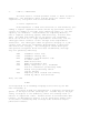
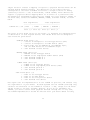
3.2 File Control Block Format
Each file being accessed through CP/M has a corresponding
file control block (FCB) which provides name and allocation
information for all file operations. The FCB is a 33-byte area
in the transient program's memory space which is set up for each
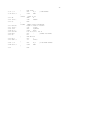
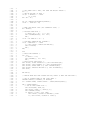
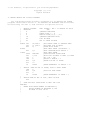
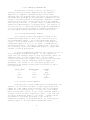
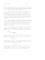
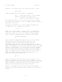
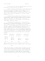
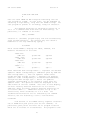
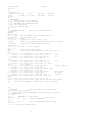
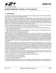
file. The FCB format is given in Figure 2. When accessing CP/M
files, it is the programmer's responsibility to fill the lower
16 bytes of the FCB, along with the CR field. Normally, the FN
and FT fields are set to the ASCII <filename> and <filetype>,
while all other fields are set to zero. Each FCB describes up
to 16K bytes of a particular file (0 to 128 records of 128 bytes
each), and, using automatic mechanisms of CP/M, up to 15 additional extensions of the file can be addressed. Thus, each FCB
can potentially describe files up to 256K bytes (which is slightly
larger than the diskette capacity).
FCB's are stored in a directory area of the diskette, and are
brought into central memory before file operations (see the OPEN
and MAKE commands) then updated in memory,as file operations proceed, and finally recorded on the diskette at the termination of
the file operation (see the CLOSE command). This organization
makes CP/M file organization highly reliable, since diskette file
integrity can only be disrupted in the unlikely case of hardware
failure during update of a single directory entry.
It should be noted that the CCP constructs an FCB for all
transients by scanning the remainder of the line following the
transient name for a <filename> or <filename>.<filetype> combination. Any field not specified is assumed to be all blanks.
A properly formed FCB is set up at location tfcb (see Section 6),
with an assumed I/0 buffer at tbuff. The transient can use tfcb
as an address in subsequent input or output operations on this
file.
10a
In addition to the default fcb which is set-up at address tfcb, the
CCP also constructs a second default fcb at address tfcb+16 (i.e., the
disk map field of the fcb at tbase). Thus, if the user types
PROGNAME X.ZOT Y.ZAP
the file PROGNAME.COM is loaded to the TPA, and the default fcb at tfcb
is initialized to the filename X with filetype ZOT. Since the user typed
a second file name, the 16 byte area beginning at tfcb + 16D is also
initialized with the filename Y and filetype ZAP. It is the responsibility
of the program to move this second filename and filetype to another area
(usually a separate file control block) before opening the file which
begins at tbase, since the open operation will fill the disk map portion,
thus cverwriting the second name and type.
If no file names were specified in the original command, then the
fields beginning at tfcb and tfcb + 16 both contain blanks (20H). If
one file name was specified, then the field at tfcb + 16 contains blanks.
If the filetype is omitted, then the field is assumed to contain blanks.
In all cases, the CCP translates lower case alphabetics to upper case
to be consistent with the CP/M file naming conventions.
As an added programming convenience, the default buffer at tbuff
is initialized to hold the entire command line past the program name.
Address thuff contains the number of characters, and tbuff+l, tbuff+2,
..., contain the remaining characters up to, but not including, the
carriage return. Given that the above command has been typed at
the console, the area beginning at thuff is set up as follows:
thuff:
+0 +1 +2 +3 +4 +5 +6 +7 +8 +9 +10 +11 +12 +13 +14 +15
12 bl X . Z 0 T bl Y .
Z
A
P
?
?
?
where 12 is the number of valid characters (in binary), and bl represents
an ASCII blank. Characters are given in ASCII upper case, with uninitialized memory following the last valid character.
Again, it is the responsibility of the program to extract the information from this buffer before any file operations are performed since
the FDOS uses the tbuff area to perform directory functions.
In a standard
boot:
entry:
tfcb:
tfcb+16
tbuff
tbase:
CP/M
system, the following values are assumed:
0000H
0005H
005CH
006CH
0080H
0100H
bootstrap load (warm start)
entry point to FDOS
first default file control block
second file name
default buffer address
base of transient,area
11
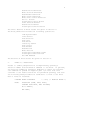
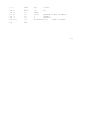
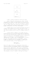
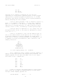
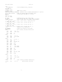
Figure 2. File Control Block Format
0 1 2 3 4 5 6 7 8 9 10 11 12 13 14 15 16 17 18 19 ... 27 28 29 30 31 32
| \_____________/ \_____/ |
| \____________________________/ |
ET
FN
FT
EX
RC
DM
NR
FIELD
FCB POSITIONS
PURPOSE
ET
0
Entry type (currently not used,
but assumed zero)
FN
1-8
File name, padded with ASCII
blanks
FT
9-11
File type, padded with ASCII
blanks
EX
12
File extent, normally set to
zero
13-14
Not used, but assumed zero
RC
15
Record count is current extent
Size (0 to 128 records)
DM
16-31
Disk allocation map, filled-in
and used by CP/M
NR
32
Next record number to read or
write
12
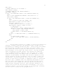
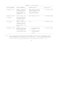
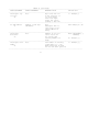
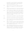
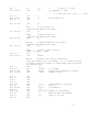
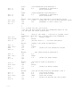
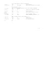
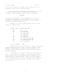
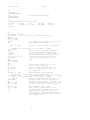
3.3 Disk Access Primitives
Given that a program has properly initialized the FCB's for
each of its files, there are several operations which can be performed, as shown in Table II. In each case, the operation is
applied to the currently selected disk (see the disk select operation in Table II), using the file information in a specific FCB.
The following PL/M program segment, for example, copies the contents of the file X.Y to the (new) file NEW.FIL:
DECLARE RET BYTE,.
OPEN:
PROCEDURE (A)
DECLARE A ADDRESS;
RET=MON2(15,A);
END OPEN;
CLOSE:
PROCEDURE (A);
DECLARE A ADDRESS;
RET=MON2(16,A);
END;
MAKE:
PROCEDURE (A);
DECLARE A ADDRESS;
RET=MON2(22.A);
END MAKE;
DELETE: PROCEDURE (A);
DECLARE A ADDRESS;
/* IGNORE RETURNED VALUE */
CALL MON1(19,A);
END DELETE;
READBF: PROCEDURE (A);
DECLARE A ADDRESS;
RET=MON2(20,A);
END READBF;
WRITEBF: PROCEDURE (A);
DECLARE A ADDRESS;
RET=MON2(2l,A);
END WRITEBF;
INIT:
PROCEDURE;
CALL MON1(13,0);
END INIT;
/* SET UP FILE CONTROL BLOCKS */
DECLARE FCB1 (33) BYTE
INITIAL (0.'X
','Y ',0,0,0,0),
FCB2 (33) BYTE
INITIAL (0.'NEW
','FIL',0,0,0,0);
13
CALL INIT;
/* ERASE 'NEW.FIL' IF IT EXISTS */
CALL DELETE (.FCB2);
/* CREATE''NEW.FIL' AND CHECK SUCCESS */
CALL MAKE (.FCB2);
IF RET = 255 THEN CALL PRINT (.'NO DIRECTORY SPACE $');
ELSE
DO; /* FILE SUCCESSFULLY CREATED, NOW OPEN 'X.Y' */
CALL OPEN (.FCB1);
IF RET = 255 THEN CALL PRINT (.'FILE NOT PRESENT $');
ELSE
DO; /* FILE X.Y FOUND AND OPENED, SET
NEXT RECORD TO ZERO FOR BOTH FILES */
FCB1(32), FCB2(32) = 0;
/* READ FILE X.Y UNTIL EOF OR ERROR */
CALL READBF (.FCB1); /*READ TO 80H*/
DO WHILE RET = 0;
CALL WRITEBF (.FCB2) /*WRITE FROM 80H*/
IF RET = 0 THEN /*GET ANOTHER RECORD*/
CALL READBF (.FCB1); ELSE
CALL PRINT (.'DISK WRITE ERROR $');
END;
IF RET < >1 THEN CALL PRINT (.' TRANSFER ERROR $');
ELSE
DO; CALL CLOSE (.FCB2);
IF RET = 255 THEN CALL PRINT (.'CLOSE ERROR$');
END;
END;
END;
EOF
This program consists of a number of utility procedures for
opening, closing, creating, and deleting files, as well as two
procedures for reading and writing data. These utility procedures
are followed by two FCB's for the input and output files. In
both caseS, the first 16 bytes are initialized to the <filename>
and <filetype> of the input and output files. The main program
first initializes the disk system, then deletes any existing
copy of "NEW.FIL" before starting. The next step is to create
a new directory entry (and empty file) for "NEW.FIL". If file
creation is successful, the input file "X.Y" is opened. If this
second operation is also successful, then the disk to disk copy
can proceed. The NR fields are set to zero so that the first
record of each file is accessed on subsequent disk I/0 operations.
The first call to READBF fills the (implied) DMA buffer at 80H
with the first record from X.Y. The loop which follows copies
the record at 80H to "NEW.PIL" and then reports any errors, or
reads another 128 bytes from X.Y. This transfer operation continues until either all data has been transferred, or an error
condition arises. If an error occurs, it in reported; otherwise
the new file is closed and the program halts.
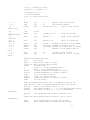
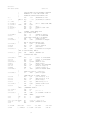
TABLE II
DISK ACCESS PRIMITIVES
----------------------------------------------------------------------------------------------FUNCTION/NUMBER
ENTRY PARAMETERS
RETURNED VALUE
TYPICAL CALL
----------------------------------------------------------------------------------------------Lift Head
None
None
CALL MON2(12,0)
12
Head is lifted from
current drive
----------------------------------------------------------------------------------------------Initialize BDOS
None
None
CALL MON1(13,0)
and select disk
Side effect is that
"A"
disk A is"loggedSet DMA address
in" while all others
to 80H
are considered "off13
line"
----------------------------------------------------------------------------------------------Log-in and
An integer value corNone
CALL MON1(14,1)
select disk
responding to the
Disk X is considered
X
disk to log-in:
on-line" and selec(log-in disk "B")
14
A=0, B=1, C=2, etc.
ted for subsequent
file operations
----------------------------------------------------------------------------------------------Open file
Address of the FCB
Byte address of the
I = MON2(15,.FCB)
15
for the file to be
FCB in the directory,
accessed
if found, or 255 if
file not present.
The DM bytes are set
by the BDOS.
----------------------------------------------------------------------------------------------Close file
Address of an FCB
Byte address of the
I = MON2(16,.FCB)
16
which has been predirectory entry corviously created or
responding to the
opened
FCB, or 255 if not
present
-----------------------------------------------------------------------------------------------
14
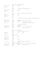
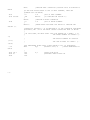
TABLE II (continued)
----------------------------------------------------------------------------------------------FUNCTION/NUMBER
ENTRY PARAMETERS
RETURNED VALUE
TYPICAL CALL
----------------------------------------------------------------------------------------------Search for file
Address of FCB conByte address of first
I = MON2(17,.FCB)
17
taining <filename>
FCB in directory that
and <filetype> to
matches input FCB, if
match. ASCII "?"
any; otherwise 255
in FCB matches any
indicates no match.
character.
----------------------------------------------------------------------------------------------Search for next
Same as above, but
Byte address of next
I = MON2(18,.FCB)
occurrence
called after func18
tion 17 no other
intermediate BDOS
calls allowed)
----------------------------------------------------------------------------------------------Delete File
Address of FCB conNone
I = MON2(19,.FC;:)
19
taining <filename>
and <filetype> of
file to delete from
diskette
----------------------------------------------------------------------------------------------Read Next Record
Address of FCB of a
0 = successful read
I = MON2(20,4FCB)
20
successfully OPENed
1 = read past end of
file, with NR set
file
to the next record
2 = reading unwritten
to read (see note 1)
data in random
access
----------------------------------------------------------------------------------------------Note 1. The
the
FCB
the
I/0 operations transfer data to/from address 80H for the next 128 bytes unless
DMA address has been altered (see function 26). Further, the NR field of the
is automatically incremented after the operation. If the NR field exceeds 128,
next extent is opened automatically, and the NR field is reset to zero.
15
TABLE II (continued)
----------------------------------------------------------------------------------------------FUNCTION/NUMBER
ENTRY PARAMETERS
RETURNED VALUE
TYPICAL CALL
----------------------------------------------------------------------------------------------Write Next Record
Same as above, except
0 = successful write
MON2(21,.FCB)
21
NR is set to the next
1 = error in extendrecord to write
ing file
2 = end of disk data
255 = no more directory space
(see note 2)
----------------------------------------------------------------------------------------------Make File
Address of FCB with
Byte address of dirMON2(22,.FCB)
22
<filename> and <fileectory entry allocatype> set. Directed to the FCB, or
tory entry is cre255 if no directory
ated, the file is
space is available
initialized to empty.
----------------------------------------------------------------------------------------------Rename FCB
Address of FCB with
Address of the dirMON2(23,.FCB)
23
old FN and FT in
ectory entry which
first 16 bytes, and
matches the first
new FN and FT in
16 bytes. The
second 16 bytes
<filename>and <filetype> is altered
255 if no match.
----------------------------------------------------------------------------------------------Note 2. There are normally 64 directory entries available on each diskette (can be
expanded to 255 entries), where one entry is required for the primary file,
and one for each additional extent.
16
TABLE II (continued)
----------------------------------------------------------------------------------------------FUNCTION/NUMBER
ENTRY PARAMETERS
RETURNED VALUE
TYPICAL CALL
----------------------------------------------------------------------------------------------Interrogate logNone
Byte value with "1"
I = MON2(24,0)
in vector
in bit positions of
24
"on line" disks,
with least significant bit corresponding to disk "A"
----------------------------------------------------------------------------------------------Set DMA address
Address of 128 byte
None
CALL MON1(26,2000H)
26
DMA buffer
Subsequent disk I/0
takes place at specified address in
memory
----------------------------------------------------------------------------------------------Interrogate
None
Address of the alloMON3: PROCEDURE(...)
Allocation
cation vector for
ADDRESS;
27
the current disk
(used by STATUS comA = MON3(27,0);
mand)
----------------------------------------------------------------------------------------------Interrogate Drive
None
Disk number of currently
I = MON2(25,0);
number
logged disk (i.e., the
25
drive which will be used
for the next disk operation
----------------------------------------------------------------------------------------------17
18
3.4 Random Access
Recall that a single FCB describes up to a 16K segment of a
(possibly) larger file. Random access within the first 16K segment is accomplished by setting the NR field to the record number
of the record to be accessed before the disk I/0 takes place.
Note, however, that if the 128th record is written, then the
BDOS automatically increments the extent field (EX), and opens
the next extent, if possible. in this case, the program must
explicitly decrement the EX field and re-open the previous extent.
If random access outside the first 16K segment is necessary,
then the extent number e be explicitly computed. given an absolute record number r as
e =
| r |
| --- |
L 128 |
or equivalently,
e = SHR(r,7)
this extent number is then placed in the EX field before the segment is opened. The NR value n is then computed as
n= r mod 128
or
n = r AND 7FH.
When the programmer expects considerable cross-segment accesses,
it may save time to create an FCB for each of the 16K segments,
open all segments for access, and compute the relevant FCB from
the absolute record number r.
4. SYSTEM GENERATION
As mentioned previously, every diskette used under CP/M is assumed to
contain the entire system (excluding transient coomnds) on the first two
tracks. The operating system need not be present, however, if the diskette
is only used as secondary disk storage on drives B, C, ..., since the CP/M
system is loaded only from drive A.
The CP/M file system is organized so that an IBM-compatible diskette
from the factory (or from a vendor which claims IBM compatibility) looks
like a diskette with an empty directory. Thus, the user must first copy
a version of the CP/M system from an existing diskette to the first two
tracks of the new diskette, followed by a sequence of copy operations,
using PIP, which transfer the transient command files from the original
diskette to the new diskette.
19
NOTE: before you begin the CP/M copy operation, read your Licensing
Agreement. It gives your exact legal obligations when making reproductions
of CP/M in whole or in part, and specifically requires that you place the
copyright notice
Copyright (c), 1976
Digital Research
on each diskette which results from the copy operation.
4.1. Initializing CP/M from an Existing Diskette
The first two tracks are placed on a new diskette by running the transient command SYSGEN, as described in the document "An Introduction to CP/M
Features and Facilities." The SYSGEN operation brings the CP/M system from
an initialized diskette into memory, and then takes the memory image and
places it on the new diskette.
Upon completion of the SYSGEN operation, place the original diskette
on drive A, and the initialized diskette on drive B. Reboot the system;
the response should be
A>
indicating that drive A is active. Log into drive B by typing
B:
and CP/M should respond with
B>
indicating that drive B is active. If the diskette in drive B is factory
fresh, it will contain an empty directory. Non-standard diskettes may,
however, appear as full directories to CP/M, which can be emptied by typing
ERA *.*
when the diskette to be initialized is active. Do not give the ERA command
if you wish to preserve files on the new diskette since all files will be
erased with this command.
After examining disk B, reboot the CP/M system and return to drive A for
further operations.
The transient commands are then copied from drive A to drive B using the
PIP program. The sequence of commands shown below, for example, copy the
principal programs from a standard CP/M diskette to the new diskette:
A>PIP
*B:STAT.COM=STAT.COM
*B:PIP.COM=PIP.COM
*B:LOAD.COM=LOAD.COM
*B.ED.COM=ED.COM
20
*B:ASM.COM=ASM.COM
*B:SYSGEN.COM=SYSGEN.COM
*B:DDT.COM=DDT.COM
*
A>
The user should then log in disk B, and type the command
DIR *.*
to ensure that the files were transferred to drive B from drive A. The
various programs can then be tested on drive B to check that they were
transferred properly.
Note that the copy operation can be simplified somewhat by creating
a "submit" file which contains the copy commands. The file could be
named GEN.SUB, for example, and might contain
SYSGEN
PIP B:STAT.COM=STAT.COM
PIP B:PIP.COM=PIP.COM
PIP B:LOAD.COM=LOAD.COM
PIP B:ED.COM=ED.COM
PIP B:ASM.COM=ASM.COM
PIP B:SYSGEN.COM=SYSGEN.COM
PIP B:DDT.COM=DDT.COM
The generation of a new diskette from the standard diskette is then done
by typing simply
SUBMIT GEN
5.
CP/M ENTRY POINT SUMMARY
The functions shown below summarize the functions of the
FDOS. The function number is passed in Register C (first parameter in PL/M), and the information is passed in Registers D,E
(second PL/M parameter). Single byte results are returned in
Register A. If a double byte result is returned, then the highorder byte comes back in Register B (normal PL/M return). The
transient program enters the FDOS through location "entry" (see
Section 7.) as shown in Section 2. for PL/M, or
CALL entry
in assembly language.
All registers are altered in the FDOS.
21
Function
--------
Number
------
Information
-----------
0
1
2
3
4
5
6
7
8
9
10
11
System Reset
Read Console
Write Console
ASCII character
Read Reader
Write Punch
ASCII character
Write List
ASCII character
(not used)
Interrogate I/0 Status
Alter I/0 Status
I/0 Status Byte
Print Console Buffer Buffer Address
Read Console Buffer
Buffer Address
Check Console Status
12
13
14
15
16
17
18
19
20
21
22
23
24
25
Lift Disk Head
Reset Disk System
Select Disk
Open File
Close File
Search First
Search Next
Delete File
Read Record
Write Record
Create File
Rename File
Interrogate Login
Interrogate Disk
26
27
Set DMA Address
DMA Address
Interrogate Allocation
Disk number
FCB Address
"
"
"
"
"
"
"
"
Result
------
ASCII character
ASCII character
I/0 Status Byte
True if character
Ready
Completion Code
"
"
"
"
"
"
"
"
Login vector
Selected Disk
Number
Address of Allocation-vector
22
6.
ADDRESS ASSIGNMENTS
The standard distribution version of CP/M is organized for an Intel
MDS microcomputer developmental system with 16K of main memory, and two
diskette drives. Larger systems are available in 16K increments, providing
management of 32K, 48K, and 64K systems (the largest MDS system is 62K
since the ROM monitor provided with the MDS resides in the top 2K of the
memory space). For each additional 16K increment, add 4000H to the values
of cbase and fbase.
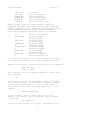
The address assignments are
boot =
tfcb =
tbuff=
tbase=
cbase=
fbase=
entry=
0000H
005CH
0080H
0100H
2900H
3200H
0005H
warm start operation
default file control block location
default buffer location
base of transient program area
base of console command processor
base of disk operating system
entry point to disk system from
user programs
23
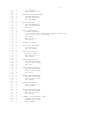
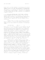
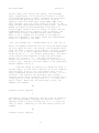
7.
SAMPLE PROGRAMS
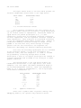
This section contains two sample programs which interface with the CP/M
operating system. The first program is written in assembly language, and
is the source program for the DUMP utility. The second program is the CP/M
LOAD utility, written in PL/M.
The assembly language program begins with a number of "equates" for system entry points and program constants. The equate
BDOS
EQU
OOOSH
for example, gives the CP/M entry point for peripheral I/0 functions. The
defualt file control block Address is also defined (FCB), along with the
default buffer address (BUFF). Note that the program is set up to run at
location 100H, which is the base of the transient program area. The stack
is first set-up by saving the entry stack pointer into OLDSP, and resetting
SP to the local stack. The stack pointer upon entry belongs to the console
command processor, and need not be saved unless control is to return to the
CCP upon exit. That is, if the program terminates with a reboot (branch to
location 0000H) then the entry stack pointer need not be saved.
The program then jumps to MAIN, past a number of subroutines which are
listed below:
BREAK - when called, checks to see if there is a console
character ready. BREAK is used to stop the listing
at the console
PCHAR - print the character which is in register A at the
console.
CRLF
- send carriage return and line feed to the console
PNIB
- print the hexadecimal value in register A in ASCII
at the console
PHEX
- print the byte value (two ASCII characters) in
register A at the console
ERR
- print error flag #n at the console, where n is
1 if file cannot be opened
2 if disk read error occurred
GNB
- get next byte of data from the input file. If the
IBP (input buffer pointer) exceeds the size of the
input buffer, then another disk record of 128 bytes
is read. Otherwise, the next character in the buffer
is returned. IBP is updated to point to the next
character.
24
The MAIN program then appears, which begins by calling SETUP. The SETUP
subroutine, discussed below, opens the input file and checks for errors.
If the file is opened properly, the GLOOP (get loop) label gets control.
On each successive pass through the GLOOP label, the next data byte
is fetched using GNB and save in register B. The line addresses are listed
every sixteen bytes, so there must be a check to see if the least significant 4 bits is zero on each output. If so, the line address is taken
from registers h and l, and typed at the left of the line. In all cases,
the byte which was previously saved in register B is brought back to
register A, following label NONUM, and printed in the output line. The
cycle through GLOOP continues until an end of file condition is detected
in DISKR, as described below. Thus, the output lines appear as
0000
0010
bb bb bb bb bb bbibb bb bb bb bb bb bb bb bb bb
bb bb bb bb bb bb bb bb bb bb bb bb bb bb bb bb
until the end of file.
The label FINIS gets control upon end of file. CRLF is called first
to return the carriage from the last line output. The CCP stack pointer
is then reclaimed from OLDSP, followed by a RET to return to the console
command processor. Note that a JMP 0000H could be used following the
FINIS label, which would cause the CP/M system to be brought in again from
the diskette (this operation is necessary only if the CCP has been overlayed by data areas).
The file control block format is then listed (FCBDN ... FCBLN) which
overlays the fcb at location 05CH which is setup by the CCP when the
DUMP program is initiated. That is, if the user types
DUMP X.Y
then the CCP sets up a properly formed fcb at location 05CH for the DUMP
(or any other) program when it goes into execution. Thus, the SETUP subroutine simply addresses this default fcb, and calls the disk system to
open it. The DISKR (disk read) routine is called whenever GNB needs another
buffer full of data. The default buffer at location 80H is used, along
with a pointer (IBP) which counts bytes a they are processed. Normally,
an end of file condition is taken as either an ASCII 1AH (control-z), or
an end of file detection by the DOS. The file dump program, however, stops
only on a DOS end of file.
25
;
;
;
;
0100
0005
000F
0014
0002
0001
000B
=
=
=
=
=
=
005C =
0080 =
0100
0103
0104
0107
010A
210000
39
220F01
315101
C3C401
010D
010F
0111
0151
0151
0154
0156
0159
015C
E5D5C5
0E0B
CD0500
C1DIL1
C9
015D
0160
0162
0163
0166
0169
E5D5C5
0E02
5F
CD0500
CID1E1
C9
016A
016C
016F
0171
0174
3E0D
CDSDOI
3E0A
CD5DO1
C9
0175 E6OF
0177 FEOA
0179 D28101
BDOS
OPENF
READF
TYPEF
CONS
BRKF
;
FCB
BUFF
;
;
FILE DUMP PROGRAM, READS AN INPUT FILE AND PRINTS IN HEX
COPYRIGHT (C), DIGITAL RESEARCH, 1975, 1976
ORG
EQU
EQU
EQU
EQU
EQU
EQU
100H
0005H
15
20
2
1
11
;DOS ENTRY POINT
;FILE OPEN
;READ FUNCTION
;TYPE FUNCTION
;READ CONSOLE
;BREAK KEY FUNCTION (TRUE IF CHAR READY)
EQU
EQU
5CH
80H
;FILE CONTROL BLOCK ADDRESS
;INPUT DISK BUFFER ADDRESS
SET UP STACK
LXI
H,0
DAD
SP
SHLD
OLDSP
LXI
SP,STKTOP
JMP
MAIN
VARIABLES
DS
2
;INPUT BUFFER POINTER
;
IBP:
;
;
STACK
AREA
OLDSP: DS
2
STACK: DS
64
STKTOP EOU
$
;
;SUBROUTINES
;
BREAK: ;CHECK BREAK KEY (ACTUALLY ANY KEY WILL DO)
PUSH H! PUSH D! PUSH B; ENVIRONMENT SAVED
MVI
C,BRKF
CALL
BDOS
POP B! POP D! POP H; ENVIRONMENT RESTORED
RET
;
PCHAR: ;PRINT A CHARACTER
PUSH H! PUSH D! PUSH B; SAVED
MVI
C,TYPEF
MOV
E,A
CALL
BDOS
POP B! POP D! POP H; RESTORED
RET
;
CRLF:
MVI
A,ODH
CALL
PCHAR
MVI
A,OAH
CALL
PCHAR
RET
;
;
PNIB:
;PRINT NIBBLE IN REG A
ANI
0FH
;LOW 4 BITS
CPI
10
JNC
P10
26
;
017C C630
017E C38301
0181 C637
0183 CD5DO1
0186 C9
;
;
P10:
PRN:
;
PHEX:
0187
0188
0189
018A
018B
018C
018F
0190
0193
F5
0F
0F
0F
0F
CD7501
Fl
CD7501
C9
;
ERR:
0194
0197
0199
019C
0190
019F
01A2
01AS
CD6A01
3E23
CD5DO1
78
C630
CD5DO1
CD6A01
C3F701
;
GNB:
01A8 3A0DO1
01AB FE80
01AD C2B401
;
;
;
0180 CD1602
01B3 AF
5F
1600
3C
320DO1
;
;
01BB
01BC
01BF
01C0
E5
218000
19
7E
;
;
;
01C1 El
01C2 23
01C3 C9
;
MAIN:
01C4 CDFF01
GREATER OR EQUAL TO 10
ADI
'A' - 10
CALL
PCHAR
RET
;PRINT HEX CHAR IN REG A
PUSH
PSW
RRC
RRC
RRC
RRC
CALL
PNIB
;PRINT NIBBLE
POP
PSW
CALL
PNIB
RET
;PRINT ERROR MESSAGE
CALL
CRLF
MVI
A,'#'
CALL
PCHAR
MOV
A,B
ADI
'0'
CALL
PCHAR
CALL
CRLF
JMP
FINIS
;GET NEXT BYTE
LDA
IBP
CPI
80H
JNZ
GO
READ
ANOTHER BUFFER
CALL
XRA
G0:
01B4
01B5
01B7
01B8
LESS THAN OR EQUAL TO 9
ADI
'0'
JMP
PRN
DISKR
A
;READ THE BYTE AT BUFF+REG A
MOV
E,A
MVI
D,0
INR
A
STA
IBP
POINTER IS INCREMENTED
SAVE THE CURRENT FILE ADDRESS
PUSH
H
LXI
H,BUFF
DAD
D
MOV
A,M
BYTE IS IN THE ACCUMULATOR
RESTORE FILE ADDRESS AND INCREMENT
POP
H
INX
H
RET
; READ AND PRINT SUCCESSIVE BUFFERS
CALL
SETUP
;SET UP INPUT FILE
27
01C7 3E80
01C9 320DO1
01CC 21FFFF
MVI
STA
LXI
A, 80H
IBP
;SET BUFFER POINTER TO 80H
H,OFFFFH
;SET TO -1 TO START
CALL
MOV
PRINT
GNB
B,A
HEX VALUES
;
GLOOP:
01CF CDA801
01D2 47
;
;
;
01D3 7D
01D4 E60F
01D6 C2EB01
;
01D9 CD6A01
;
;
01DC CD5101
01DF 0F
01E0 DAF701
CHECK FOR LINE FOLD
MOV
A,L
ANI
0FH
;CHECK LOW 4 BITS
JNZ
NONUM
PRINT
LINE NUMBER
CALL
CRLF
CHECK
CALL
RRC
JC
FOR BREAK KEY
BREAK
MOV
CALL
mov
CALL
A,H
PHEX
A,L
PHEX
MVI
CALL
MOV
CALL
A,' '
PCHAR
A,B
PHEX
JMP
GLOOP
FINIS
;DON'T PRINT ANY MORE
;
01E3
01E4
01E7
01E8
7C
CD8701
7D
CD8701
01EB
01ED
01F0
01F1
3E20
CD5D01
78
CD8701
NONUM:
01F4 C3CF01
;
EPSA:
;END PSA
;END OF INPUT
FINIS:
01F7
01FA
01FD
01FE
005C
005D
0065
0068
006B
007C
007D
CD6A01
2A0F01
F9
C9
=
=
=
=
=
=
=
CALL
LHLD
SPHL
RET
;
;
;
FCBDN
FCBFN
FCBFT
FCBRL
FCBRC
FCBCR
FCBLN
;
;
SETUP:
;
01FF 115C00
0202 0E0F
0204 CD0500
;
0207 FEFF
0209 C21102
CRLF
OLDSP
FILE CONTROL BLOCK DEFINITIONS
EOU
FCB+0
;DISK NAME
EQU
FCB+1
;FILE NAME
EQU
FCB+9
;DISK FILE TYPE (3 CHARACTERS)
EOU
FCB+12 ;FILE'S CURRENT REEL NUMBER
EQU
FCB+15 ;FILE'S RECORD COUNT (0 TO 128)
EQU
FCB+32 ;CURRENT (NEXT) RECORD NUMBER (0 TO 127)
EQU
FCB+33 ;FCB LENGTH
;SET UP FILE
OPEN THE FILE FOR INPUT
LXI
D,FCB
MVI
C,OPENF
CALL
BOOS
CHECK
FOR ERRORS
CPI
255
JNZ
OPNOK
28
;
020C 0601
020E CD9401
;
OPNOK:
0211 AF
0212 327C00
0215 C9
;
DISKR:
0216
0219
021C
021E
0221
0224
0226
E5D5C5
115C00
0E14
CD0500
C1D1E1
FEOO
C8
;
0227 FE01
0229 CAF701
BAD OPEN
MVI
B,1
CALL
ERR
;OPEN ERROR
;OPEN IS OK.
XRA
A
STA
FCBCR
RET
;READ DISK FILE RECORD
PUSH H! PUSH D! PUSH B
LXI
D,FCB
MVI
C,READF
CALL
BDOS
POP B! POP D! POP H
CPI
0
;CHECK FOR ERRS
RZ
MAY BE EOF
CPI
1
JZ
FINIS
;
022C 0602
022E CD9401
MVI
CALL
;
0231
END
B,2
ERR
;DISK READ ERROR
29
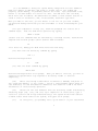
The PL/M program which follows implements the CP/M LOAD utility.
function is as follows. The user types
The
LOAD filename
If filename.HEX exists on the diskette, then the LOAD utility reads the "hex"
formatted machine code file and produces the file
filename.COM
where the COM file contains an absolute memory image of the machine code,
ready for load and execution in the TPA. If the file does not appear on
the diskette, the LOAD program types
SOURCE IS READER
and reads an Addmaster paper tape reader which contains the hex file.
The LOAD program is set up to load and run in the TPA, and, upon completion, return to the CCP without rebooting the system. Thus, the program is constructed as a single procedure called LOADCOM which takes the
form
0FAH:
LOADCOM: PROCEDURE;
/* LIBRARY PROCEDURES */
MON1: ...
/* END LIBRARY PROCEDURES */
MOVE: ...
GETCHAR: ...
PRINTNIB: ...
PRINTHEX: ...
PRINTADDR: ...
RELOC: ...
SETMEM:
RFADHEX:
READBYTE:
READCS:
MAKEDOUBLE:
DIAGNOSE:
END RELOC;
DECLARE STACK(16) ADDRESS, SP ADDRESS;
SP = STACKPTR; STACKPTR = .STACK(LENGTH(STACK));
...
CALL REIOC;
...
STACKPTR = SP;
RETURN 0;
END LOADCOM;
;
EOF
30
The label 0FAH at the beginning sets the origin of the compilation to 0FAH,
which causes the first 6 bytes of the compilation to be ignored when loaded
(i.e., the TPA starts at location 100H and thus 0FAH,...,0FFH are deleted
from the COM file). In a PL/M compilation, these 6 bytes are used to set up
the stack pointer and branch around the subroutines in the program. In this
case, there is only one subroutine, called LOADCOM, which results in the
following machine memory image for LOAD
0FAH:
0FDH:
100H:
LXI SP,plmstack
;SET SP TO DEFAULT STACK
JMP pastsubr
;JUMP AROUND LOADCOM
beginning of LOADCOM procedure
....
end of LOADCOM procedure
RET
pastsubr:
EI
HLT
Since the machine code between OFAH and OFFH is deleted in the load,
execution actually begins at the top of LOADCOM. Note, however, that
the initialization of the SP to the default stack has also been deleted;
thus, there is a declaration and initialization of an explicit stack and
stack pointer before the call to RELOC at the end of LOADCOM. This is
necessary only if we wish to return to the CCP without a reboot operation:
otherwise the origin of the program is set to 100H, the declaration of
LOADCOM as a procedure is not necessary, and termination is accomplished
by simply executing a
GO TO 0000H;
at the end of the program. Note also that the overhead for a system reboot is not great (approximately 2 seconds), but can be bothersome for
system utilities which are used quite often, and do not need the extra
space.
The procedures listed in LOADCOM as "library procedures" are a standard
set of PL/M subroutines which are useful for CP/M interface. The RELOC
procedure contains several nested subroutines for local functions, and
actually performs the load operation when called from LOADCOM. Control
initially starts on line 327 where the stackpointer is saved and re-initialized
to the local stack. The default file control block name is copied to
another file control block (SFCB) since two files may be open at the same
time. The program then calls SEARCH to see if the HEX file exists; if not,
then the high speed reader is used. If the file does exist, it is opened for
input (if possible). The filetype ODM is moved to the default file control
block area, and any existing copies of filename.COM files are removed from
the diskette before creating a new file. The MAKE operation creates a new
file, and, if successful, RELOC is called to read the HEX file and produce
the COM file. At the end of processing by RELOC, the COM file is closed
(line 350). Note that the HEX file does not need to be closed since it
was opened for input only. The data written to a file is not permanently
recorded until the file is successfully closed.
31
Disk input characters are read through the procedure GETCHAR on line
137. Although the DMA facilities of CP/M could be used here, the GETCHAR
procedure instead uses the default buffer at location 80H and moves each
buffer into a vector called SBUFF (source buffer) as it is read. on exit,
the GETCHAR procedure returns the next input character and updates the
source buffer pointer (SBP).
The SETMEM procedure on line 191 performs the opposite function from
GETCHAR. The SETMEM procedure maintains a buffer of loaded machine code
in pure binary form which acts as a "window" on the loaded code. If there
is an attempt by RELOC to write below this window, then the data is ignored.
If the data is within the window, then it is placed into MBUFF (memory
buffer). If the data is to be placed above this window, then the window
is moved up to the point where it would include the data address by writing
the memory image successively (by 128 byte buffers), and moving the base
address of the window. Using this technique, the programmer can recover
from checksum errors on the high-speed reader by stopping the reader,
rewinding the tape for some distance, then restarting LOAD (in this case,
LOADing is resumed by interrupting with a NOP instruction). Again, the
SETMEM procedure uses the default buffer at location 80H to perform the
disk output by moving 128 byte segments to 80H through 0FFH before each
write.
32
00001
00002
00003
00004
00005
00006
00007
00008
00009
00010
00011
00012
00013
00014
00015
00016
00017
00018
00019
00020
00021
00022
00023
00024
00025
00026
00027
00028
00029
00030
00031
00032
00033
00034
00035
00036
00037
00038
00039
00040
00041
00042
00043
00044
00045
00046
00047
00048
00049
00050
1
1
1
1
1
1
1
1
1
2
2
2
2
2
2
2
2
2
2
2
2
2
2
2
2
2
2
2
2
3
3
3
3
2
2
3
3
3
3
2
2
3
3
3
2
2
2
2
2
2
0FAH: DECLARE BDOS LITERALLY '0005H';
/* TRANSIENT COMMAND LOADER PROGRAM
COPYRIGHT (C) DIGITAL RESEARCH
JUNE, 1975
*/
LOADCOM: PROCEDURE BYTE;
DECLARE FCBA ADDRESS INITIAL(5CH);
DECLARE FCB BASED FCBA (33) BYTE;
DECLARE BUFFA ADDRESS INITIAL(80H), /* I/0 BUFFER ADDRESS */
BUFFER BASED BUFFA (128) BYTE;
DECLARE SFCB(33) BYTE, /* SOURCE FILE CONTROL BLOCK */
BSIZE LITERALLY '1024-',
EOFILE LITERALLY '1AH',
SBUFF(BSIZE) BYTE /* SOURCE FILE BUFFER */
INITIAL(EOFILE),
RFLAG BYTE,
/*
READER FLAG */
SBP ADDRESS;
/*
SOURCE FILE BUFFER POINTER */
/* LOADCOM LOADS TRANSIENT COMMAND FILES TO THE DISK FROM THE
CURRENTLY DEFINED READER PERIPHERAL. THE LOADER PLACES THE MACH
CODE INTO A FILE WHICH APPEARS IN THE LOADCOM COMMAND */
/* ***************** LIBRARY PROCEDURES FOR DISKIO *************** */
MON1: PROCEDURE(F,A);
DECLARE F BYTE,
A ADDRESS;
GO TO BDOS;
END MON1;
MON2: PROCEDURE(F,A) BYTE;
DECLARE F BYTE,
A ADDRESS;
GO TO BDOS;
END MON2;
READRDR: PROCEDURE BYTE;
/* READ CURRENT READER DEVICE */
RETURN MON2(3,0);
END READRDR;
DECLARE
TRUE LITERALLY '1',
FALSE LITERALLY '0',
FOREVER LITERALLY 'WHILE TRUE',
CR LITERALLY '13',
33
00051
00052
00053
00054
00055
00056
00057
00058
00059
00060
00061
00062
00063
00064
00065
00066
00067
00068
00069
00070
00071
00072
00073
00074
00075
00076
00077
00078
00079
00080
00081
00082
00083
00084
00085
00086
00087
00088
00089
00090
00091
00092
00093
00094
00095
00096
00097
00098
00099
00100
00101
00102
00103
00104
00105
00106
00107
00108
00109
00110
2
2
2
2
3
3
3
2
2
3
3
3
2
2
3
3
3
3
3
3
2
2
2
2
3
3
2
2
3
3
3
2
2
3
3
3
2
2
3
3
3
2
2
3
3
3
2
2
3
3
2
2
3
3
3
2
2
3
3
3
LF LITERALLY '10',
WHAT LITERALLY '63';
PRINTCHAR: PROCEDURE(CHAR);
DECLARE CHAR BYTE;
CALL MON1(2,CHAR);
END PRINTCHAR;
CRLF: PROCEDURE;
CALL PRINTCHAR(CR);
CALL PRINTCHAR(LF);
END CRLF;
PRINT: PROCEDURE(A);
DECLARE A ADDRESS;
/* PRINT THE STRING STARTING AT ADDRESS A UNTIL THE
NEXT DOLLAR SIGN IS ENCOUNTERED */
CALL CRLF;
CALL MON1(9,A);
END PRINT;.
DECLARE DCNT BYTE;
INITIALIZE: PROCEDURE;
CALL MON1(13,0);
END INITIALIZE;
SELECT: PROCEDURE(D);
DECLARE D BYTE;
CALL MON1(14,D);
END SELECT;
OPEN: PROCEDURE(FCB);
DECLARE FCB ADDRESS;
DCNT = MON2(15,FCB);
END OPEN;
CLOSE: PROCEDURE(FCB);
DECLARE FCB ADDRESS;
DCNT = MON2(16,FCB);
END CLOSE;
SEARCH: PROCEDURE(FCB);
DECLARE FCB ADDRESS;
DCNT = MON2(17,FCB);
END SEARCH;
SEARCHN: PROCEDURE;
DCNT = MON2(18,0);
END SEARCHN;
DELETE: PROCEDURE(FCB);
DECLARE FCB ADDRESS;
CALL MON1(19,FCB);
END DELETE;
DISKREAD: PROCEDURE(FCB) BYTE;
DECLARE FCB ADDRESS;
RETURN MON2(20,FCB);
END DISKREAD;
34
00111
00112
00113
00114
00115
00116
2
2
3
3
3
2
00117
00118
00119
00120
00121
00122
00123
00124
00125
00126
00127
00128
00129
00130
00131
00132
00133
00134
00135
00136
00137
00138
00139
00140
00141
00142
00143
00144
00145
00146
00147
00148
00149
00150
00151
00152
00153
00154
00155
00156
00157
00158
00159
00160
00161
00162
00163
00164
00165
00166
00167
00168
2
3
3
3
2
2
3
3
3
2
2
2
2
3
3
3
3
4
3
2
2
3
3
3
3
3
3
3
3
4
4
5
5
5
4
3
3
2
2
2
2
2
3
3
3
3
2
2
3
3
3
2
DISKWRITE: PROCEDURE(FCB) BYTE;
DECLARE FCB ADDRESS;
RETURN MON2(2l,FCB);
END DISKWRITE;
MAKE: PROCEDURE(FCB);
DECLARE FCB ADDRESS;
DCNT = MON2(22,FCB);
END MAKE;
RENAME: PROCEDURE(FCB);
DECLARE FCB ADDRESS;
CALL MON1(23,FCB);
END RENAME;
/* ******************* END OF LIBRARY PROCEDURES ************** */
MOVE: PR6CEDURE(S,D,N);
DECLARE (S,D) ADDRESS, N BYTE,
A BASED S BYTE, B BASED D BYTE;
DO WHILE (N:=N-1) <> 255;
B = A; S=S+1; D=D+1;
END;
END MOVE;
GETCHAR: PROCEDURE BYTE;
/* GET NEXT CHARACTER */
DECLARE I BYTE;
IF RFLAG THEN RETURN READRDR;
IF (SBP := SBP+1) <= LAST(SBUFF) THEN
RETURN SBUFF(SBP);
/* OTHERWISE READ ANOTHER BUFFER FULL */
DO SBP = 0 TO LAST(SBUFF) BY 128;
IF (I:=DISKREAD(.SFCB)) = 0 THEN
CALL MOVE(80H,.SBUFF(SBP),80H); ELSE
DO; IF 1<>1 THEN CALL PRINT(.'DISK READ ERROR$');
SBUFF(SBP) = EOFILE;
SBP = LAST(SBUFF);
END;
END;
SBP = 0; RETURN SBUFF;
END GETCHAR;
DECLARE
STACKPOINTER LITERALLY 'STACKPTR';
PRINTNIB: PROCEDURE(N);
DECLARE N BYTE;
IF N > 9 THEN CALL PRINTCHAR(N+'A'-10); ELSE
CALL PRINTCHAR(N+'0');
END PRINTNIB;
PRINTHEX: PROCEDURE(B);
DECLARE B BYTE;
CALL PRINTNIB(SHR(B,4)); CALL PRINTNIB(B AND 0FH);
END PRINTHEX;
35
00169
00170
00171
00172
00173
00174
00175
00176
00177
00178
00179
00180
00181
00182
00183
00184
00185
00186
00187
00188
00189
00190
00191
00192
00193
00194
00195
00196
00197
00198
00199
00200
00201
00202
00203
00204
00205
00206
00207
00208
00209
00210
00211
00212
00213
00214
00215
00216
00217
00218
00219
00220
00221
00222
00223
00224
00225
2
3
3
3
2
2
2
2
2
3
3
3
3
3
3
3
3
3
3
3
3
3
3
4
4
4
4
4
5
6
5
5
5
5
6
6
6
6
5
4
4
3
3
4
4
4
4
4
4
3
3
4
4
4
3
3
4
PRINTADDR: PROCEDURE(A);
DECLARE A ADDRESS;
CALL PRINTHEX(HIGH(A)); CALL PRINTHEX(LOW(A));
END PRINTADDR;
/* INTEL HEX FORMAT LOADER */
RELOC: PROCEDURE;
DECLARE (RL, CS, RT) BYTE;
DECLARE
LA ADDRESS,
/* LOAD ADDRESS */
TA ADDRESS,
/* TEMP ADDRESS */
SA ADDRESS,
/* START ADDRESS */
FA ADDRESS,
/* FINAL ADDRESS */
NB ADDRESS,
/* NUMBER OF BYTES LOADED */
SP ADDRESS,
/* STACK POINTER UPON ENTRY TO RELOC */
MBUFF(256) BYTE,
P BYTE,
L ADDRESS;
SETMEM: PROCEDURE(B);
/* SET MBUFF TO B AT LOCATION LA MOD LENGTH(MBUFF) */
DECLARE (B,I) BYTE;
IF LA < L THEN /* MAY BE A RETRY */ RETURN;
DO WHILE LA > L + LAST(MBUFF); /* WRITE A PARAGRAPH */
DO I = 0 TO 127; /* COPY INTO BUFFER */
BUFFER(I) = MBUFF(LOW(L)); L = L + 1;
END;
/* WRITE BUFFER ONTO DISK */
P = P + 1;
IF DISKWRITE(FCBA) <> 0 THEN
DO; CALL PRINT(.'DISK WRITE ERROR$');
HALT;
/* RETRY AFTER INTERRUPT NOP */
L = L - 128;
END;
END;
MBUFF(LOW(LA)) = B;
END SETMEM;
READHEX: PROCEDURE BYTE;
/* READ ONE HEX CHARACTER FROM THE INPUT */
DECLARE H BYTE;
IF (H := GETCHAR) - '0' <= 9 THEN RETURN H - '0';
IF H - 'A' > 5 THEN GO TO CHARERR;
RETURN H - 'A' + 10;
END READHEX;
READBYTE: PROCEDURE BYTE;
/* READ TWO HEX DIGITS */
RETURN SHL(READHEX,4) OR READHEX;
END READBYTE;
READCS: PROCEDURE BYTE;
/* READ BYTE WHILE COMPUTING CHECKSUM */
36
00226
00227
00228
00229
00230
00231
00232
00233
00234
00235
00236
00237
00238
00239
00240
00241
00242
00243
00244
00245
00246
00247
00248
00249
00250
00251
00252
00253
00254
00255
00256
00257
00258
00259
00260
00261
00262
00263
00264
00265
00266
00267
00268
00269
00270
00271
00272
00273
00274
00275
00276
00277
00278
00279
4
4
4
4
3
3
4
4
4
4
3
3
4
4
4
4
5
5
5
4
4
4
4
4
4
4
4
5
5
5
4
4
4
3
3
3
3
3
3
3
3
3
3
4
4
4
3
3
3
3
3
3
3
4
DECLARE B BYTE;
CS = CS + (B := READBYTE);
RETURN B;
END READCS;
MAKE$DOUBLE: PROCEDURE(H,L) ADDRESS;
/* CREATE A BOUBLE BYTE VALUE FROM TWO SINGLE BYTES */
DECLARE (H,L) BYTE;
RETURN SHL(DOUBLE(H),8) OR L;
END MAKE$DOUBLE;
DIAGNOSE: PROCEDURE;
DECLARE M BASED TA BYTE;
NEWLINE: PROCEDURE;
CALL CRLF; CALL PRINTADDR(TA); CALL PRINTCHAR(':');
CALL PRINTCHAR(' ');
END NEWLINE;
/* PRINT DIAGNOSTIC INFORMATION AT THE CONSOLE */
CALL PRINT(.'LOAD ADDRESS $'); CALL 'PRINTADDR(TA);
CALL PRINT(.'ERROR ADDRESS $'); CALL PRINTADDR(LA);
CALL PRINT(.'BYTES READ:$'); CALL NEWLINE;
DO WHILE TA < LA;
IF (LOW(TA) AND 0FH) = 0 THEN CALL NEWLINE;
CALL PRINTHEX(MBUFF(TA-L)); TA=TA+1;
CALL PRINTCHAR( ');
END;
CALL CRLF;
HALT;
END DIAGNOSE;
/* INITIALIZE */
SA, FA, NB = 0;
SP = STACKPOINTER;
P = 0; /* PARAGRAPH COUNT */
TA,LA,L = 100H; /* BASE ADDRESS OF TRANSIENT ROUTINES */
IF FALSE THEN
CHARERR: /* ARRIVE HERE IF NON-HEX DIGIT IS ENCOUNTERED */
DO; /* RESTORE STACKPOINTER */ STACKPOINTER = SP;
CALL PRINT(.'NON-HEXADECIMAL DIGIT ENCOUNTERED $');
CALL DIAGNOSE;
END;
/* READ RECORDS UNTIL :00XXXX IS ENCOUNTERED */
DO FOREVER;
/* SCAN THE : */
DO WHILE GETCHAR <> ':';
END;
37
00280
00281
00282
00283
00284
00285
00286
00287
00288
00289
00290
00291
00292
00293
00294
00295
00296
00297
00298
00299
00300
00301
00302
00303
00304
00305
00306
00307
00308
00309
00310
00311
00312
00313
00314
00315
00316
00317
00318
00319
00320
00321
00322
00323
00324
00325
00326
00327
00328
00329
00330
00331
00332
00333
00334
00335
00336
4
4
4
4
4
4
4
4
4
4
4
4
4
4
4
4
4
4
5
4
4
4
4
4
5
5
4
3
3
3
3
3
3
4
3
3
3
3
3
3
3
3
2
2
2
2
2
2
2
2
2
2
2
2
2
2
2
/*
CS
/*
IF
SET CHECK SUM TO ZERO, AND SAVE THE RECORD LENGTH */
= 0;
MAY BE THE END OF TAPE */
(RL := READCS) = 0 THEN
GO TO FIN;
NB = NB + RL;
TA, LA = MAKE$DOUBLE(READCS,READCS);
IF SA = 0 THEN SA = LA;
/* READ THE RECORD TYPE (NOT CURRENTLY USED) */
RT = READCS;
/* PROCESS EACH BYTE */
DO WHILE (RL := RL - 1) <> 255;
CALL SETMEM(READCS); LA = LA+1;
END;
IF LA > FA THEN FA = LA - 1;
/* NOW READ CHECKSUM AND COMPARE */
IF CS + READBYTE <> 0 THEN
DO; CALL PRINT(.'CHECK SUM ERROR$');
CALL DIAGNOSE;
END;
END;
FIN:
/* EMPTY THE BUFFERS */
TA = LA;
DO WHILE L < TA;
CALL SETMEM(0); LA = LA+1;
END;
/* PRINT FINAL STATISTICS */
CALL PRINT(.'FIRST ADDRESS $'); CALL PRINTADDR(SA);
CALL PRINT(.'LAST ADDRESS $'); CALL PRINTADDR(FA);
CALL PRINT(.'BYTES READ $'); CALL PRINTADDR(NB);
CALL PRINT(.'RECORDS WRITTEN $'); CALL PRINTHEX(P);
CALL CRLF;
END RELOC;
/* ARRIVE HERE FROM THE SYSTEM MONITOR, READY TO READ THE HEX TAPE */
/* SET UP STACKPOINTER IN THE LOCAL AREA */
DECLARE STACK(16) ADDRESS, SP ADDRESS;
SP = STACKPOINTER; STACKPOINTER = .STACK(LENGTH(STACK));
SBP = LENGTH(SBUFF);
/* SET UP THE SOURCE FILE */
CALL MOVE(FCBA,.SFCB,33);
CALL MOVE(.('HEX',0),.SFCB(9),4);
CALL SEARCH(.SFCB);
IF (RFLAG := DCNT = 255) THEN
CALL PRINT(.'SOURCE IS READER$'); ELSE
DO; CALL PRINT(.'SOURCE IS DISK$');
00337
00338
00339
00340
00341
00342
00343
00344
00345
00346
00347
00348
00349
00350
00351
00352
00353
00354
00355
00356
00357
00358
00359
00360
3
3
3
2
2
2
2
2
2
2
2
2
2
3
3
3
2
2
2
2
2
2
1
1
38
CALL OPEN(.SFCB);
IF DCNT = 255 THEN CALL PRINT(.'-CANNOT OPEN SOURCE$');
END;
CALL CRLF;
CALL MOVE(.'COM',FCBA+9,3);
/* REMOVE ANY EXISTING FILE BY THIS NAME */
CALL DELETE(FCBA);
/* THEN OPEN A NEW FILE */
CALL MAKE(FCBA); FCB(32) = 0; /* CREATE AND SET NEXT RECORD */
IF DCNT = 255 THEN CALL PRINT(.'NO MORE DIRECTORY SPACE$'); ELSE
DO; CALL RELOC;
CALL CLOSE(FCBA);
IF DCNT = 255 THEN CALL PRINT(.'CANNOT CLOSE FILE$');
END;
CALL CRLF;
/* RESTORE STACKPOINTER FOR RETURN */
STACKPOINTER = SP;
RETURN 0;
END LOADCOM;
EOF
C P / M
1 . 4
A L T E R A T I O N
G U I D E
Table of Contents
Section
l.
INTRODUCTION
2.
FIRST LEVEL SYSTEM REGENERATION
3.
SECOND LEVEL SYSTEM REGENERATION
4.
SAMPLE GETSYS AND PURSYS PROGRAMS
5.
DISKETTE ORGANIZATION
6.
THE BIOS ENTRY POINTS
7.
A SAMPLE BIOS
8.
A SAMPLE COLD START LOADER
9.
RESERVED LOCATIONS IN PAGE ZERO
Appendix
A.
THE MDS LOADER MOVE PROGRAM
B.
THE MDS COLD START LMDER
C.
THE MDS BASIC I/0 SYSTEM (BIOS)
D.
A SKELETAL CBIOS
E.
A SKELETAL GETSYS/PUTSYS PROGRAM
F.
A SKELETAL COLD START LOADER
Page
1
1
5
8
9
11
17
17
17
CP/M System Alteration Guide
1. INTRODUCTION
The standard CP/M system assumes operation on an Intel MDS microcomputer
development system, but is designed so that the user can alter a specific set
of subroutines which define the hardware operating enviornment. In this way,
the user can produce a diskette which operates with a non-standard (but
IBM-compatible format) drive controller and/or peripheral devices.
In order to achieve device independence, CP/M is separated into three
distinct modules:
BIOS - basic I/0 system which is environment dependent
BDOS - basic disk operating system which is not dependent unon
the hardware configuration
CCP - the console command processor which uses the BDOS
of these mdules, only the BIOS is dependent upon the particular hardware.
That is, the user can "patch" the distribution version of CP/M to provide a
new BIOS which provides a customized interface between the remaining CP/M
modules and the user's own hardware system. The purpose of this document is
to provide a step-by-step procedure for patchinq the new BIOS into CP/M.
The new BIOS requires some relatively simple software development and
testing; the current BIOS, however, is listed in Appendix C, and can be used
as a model for the customized packaqe. A skeletal version of the BIOS is
given in Appendix D which can form the base for a modified BIOS. In addition
to the BIOS, the user must write a simple memory loader, called GETSYS, which
brings the operating system into memory. In order to patch the new BIOS into
CP/M, the user must write the reverse of GETSYS, called PUTSYS, which places
an altered version of CP/M back onto the diskette. PUTSYS is usually derived
from GETSYS by chanqinq the disk read commands into disk write commands.
Sample skeletal GETSYS and PUTSYS programs are described in Section 3, and
listed in Appendix E. In order to make the CP/M system work automatically,
the user must also supply a cold start loader, similar to the one provided wi
CP/M (listed in Appendices A and B). A skeletal form of a cold start loader
is given in Appendix F which can serve as a model for your leader.
2. FIRST LEVEL SYSTEM REGENERNTION
The procedure to follow to patch the CP/M system is given below in several
steps. Address references in each step are shown with a following "H" which
denotes the hexadecimal radix, and are given for a 16K CP/M system. For
larger CP/M systems, add a "bias" to each address which is shown with a "+b"
following it, where b is actual to the memory size - 16K.
Values for b in
various standard memory sizes are
32K:
b = 32K - 16K = 16K = 04000H
1
48K:
62K:
64K:
b = 48K = 16K = 32K = 08000H
b = 62K = 16K = 46K = 0B800H
b = 64K = 16K = 48K = 0C000H
(1) Review Section 4 and write a GETSYS program which reads the first two
tracks of a diskette into memory. The data from the diskette must begin at
location 2880H+b. Code GETSYS so that it starts at location 100H (base of the
TPA), as shown in the first part of Appendix E.
(2) Test the GE'ISYS program by reading a blank diskette into memory, and
check to see that the data has been read properly, and that the diskette has
not been altered in any way by the GETSYS program.
(3) Run the GETSYS program using an initialized CP/M diskette to see if
GETSYS loads CP/M startinq at 2880H+b (the operating system actually starts
128 bytes later at 2900H+b)
(4)
Review Section 4 and write the PUTSYS Program which writes memory
starting at 2880H+b back onto the first two tracks of the diskette. The
PU.RSYS proqram should be located at 200H, as shown in the second part of
Appendix E.
(5)
Test the PUTSYS program using a blank uninitialized diskette by
writing a portion of memory to the first two tracks; clear memory and read it
back using GETSYS. Test PUTSYS completely, since this program will be used to
alter CP/M on disk.
(6)
Study Sections 5, 6, and 7, along with the distribution version of
the BIOS given in Appendix C, and write a simple version vhich performs a
similar function for the customized environment. Use the program given in
Appendix D as a model. Call this new BIOS by the name CBIOS (customized
BIOS). Implement only the primitive disk operations on a single drive, and
simple console input/output functions in this phase.
(7)
Test CBIOS completely to ensure that it properly performs console
character I/0 and disk reads and writes. Be especially careful to ensure that
no disk write operations occur accidently durinq read operations, and check
that the proper track and sectors are addressed on all reads and writes.
Failure to make these checks way cause distruction of the initialized CP/M
system after it is patched.
(8) Referring to Figure 1 in Section 5, note that the BIOS is located
between locations 3E00H+b and 3FFFH+b. Read the CP/M system using GETSYS and
replace the BIOS segment by the new CBIOS developed in step (6) and tested in
step (7). This replacement is done in the memory of the machine, and will be
placed on the diskette in the next step.
(9) Use PUTSYS to place the patched memory image of CP/M onto the first
two tracks of a blank diskette for testinq.
2
(10) Use GETSYS to bring the copied memory image from the test diskette
back into memory at 2880H+b, and check to ensure that it has loaded @ck
properly (clear memory, if possible, before the load). Upon,successful load,
branch to the CCP module at location 2900H+b. The CCP will call the BDOS,
which will call the CBIOS. The CBIOS will be asked to read several sectors on
track 2 twice in succession, and, if successful, CP/M will type "A>".
When you make it this far, you are almost on the air. If you have trouble,
use whatever debug facilities you have available to trace and breakpoint your
CBIOS.
(11) Upon completion of step (10), CP/M has prompted the console for a
command input. Test the disk write operation by typing
SAVE 1 X.COM
(recall that all commands must be followed by a carriage return). CP/M should
respond with another prompt (after several disk accesses):
A>
If it does not, debug your disk write functions and retry.
(12) Then test the directory command by typing
DIR *.*
CP/M should respond with
X
COM
(13) Test the erase command by typing
ERA X.COM
CP/M should respond with the A prompt. When you make it this far, you have an
operational system which only requires a bootstrap loader to function
completely.
(14)
Write a bootstrap loader which is similar to GETSYS, and place it
into read-only-memory, or into track 0, sector 1 usinq PUTSYS (again using the
test diskette, not the distribution diskette). See Sections 5 and 8 for more
information on the bootstrap operation.
(15)
Retest the new test diskette with the bootstrap loader installed by
executing steps (11), (12), and (13). Upon completion of these tests, type a
control-C (control and C keys simultaneously). The system should then execute
a "warm start" which reboots the system, and types the A prompt.
(16)
At this point, you probably have a good version of your customized
3
CP/M system on your test diskette. Use GETSYS to load CP/M from your test
diskette.
Remove the test diskette place the distribution diskette (or a
legal copy) into the drive, and use PUTSYS to replace the distribution version
by your customized version. Do not make this replacement if you are unsure of
your patch since this step destroys the system which was sent to you from
Digital Research.
(17) Load your modified CP/M system and test it by typing
DIR
CP/M should respond with a list of files which are provided on the initialized
diskette. One such file should be the memory image for the debugger, called
DDT.COM.
NOTE: from now on, it is important that you always reboot
the CP/M system when the diskette is removed and replaced
by another diskette, unless the new diskette is read-only.
(18)
Load and test the debugger by typing
DDT
(see the document "CP/M Dynamic Debugging Tool (DDT)" for operating
information and examples). Take time to familiarize yourself with DDT; it
will be your best friend in later steps.
(19) Before making further CBIOS modifications, practice using the editor
(see the ED user's guide), and assembler (see the ASM user's guide). Then
recode and test the GETSYS, RJTSYS, and CBIOS programs using ED, ASM, and
DDT. Code and test a COPY program which does a sector-to-sector copy from one
diskette to another to obtain back-up copies of the original diskette (NOTE:
read your CP/M Licensing Agreement; it specifies your legal responsibilities
when copying the CP/M system). Place the copyright notice
Copyright (c) 1976
Digital Research
on each copy vbich is made with your COPY program.
(20)
Modify your CBIOS to include the extra functions for punches,
readers, siqnon messages, and so-forth, and add the facilities for a second
drive, if it exists on your system. You can make these changes with the
GETSYS and PUTSYS programs which you have developed, or you can refer to the
following section, which outlines CP/M facilities which will aid you in the
regeneration process.
You now have a good copy of the customized CP/M system. Note that
although the CBICS portion of CP/M which you have developed belongs to you,
the modified version of CP/M which you have created can be copied for your use
only (again, read your Licensing Agreement), and cannot be legally copied for
4
anyone else's use. If you wish, you may send vou name and address to Digital
Research, along with a description of your hardware environment and the
modifications which you have made. Diaital Research will make the information
available to other interested parties, and inform them of the prices and
availability of your CBIOS.
It should be noted that your system remains file-compatible with all other
CP/M systems, which allows transfer of non-proprietary software between users
of CP/M.
3. SECOND LEVEL SYSTEM GENERATION
Now that you have the CP/M system running, you may wish to use CP/M
facilities in the system regeneration process. In general, we will first qet
a memory image of CP/M from the first two tracks of an initialized diskette
and place this memory image into a named disk file. The disk file can then be
loaded, examined, patched, and replaced using the editor, assembler, debugger,
and system generation program.
The SYSGEN program, supplied with your diskette, is first used to get a
CP/M memory image from the first two tracks. Run the SYSGEN program as shown
below
SYSGEN
*SYSGEN VERSION 1.0
GET SYSTEM (Y/N)?Y
SOURCE ON B, THEN TYPE RETURN
start the SYSGEN program
SYSGEN siqnon messace
Answer yes to GET request
at this point, place an initialized diskette into drive B and type a return
(if you are operating with a single drive, answer "A" to the GET request,
rather than "Y", and place the initialized diskette into drive A before typinq
the return). The program should respond with:
FUNCTION COMPLETE
PUT SYSTEM (Y/N)?N
Load is complete
Answer no to PUT request
system will automatically reboot at this point, with the memory image loaded
into memory starting at location 900H and ending at 207FH in the transient
program area. The memory image for CP/M can then be saved (if you are
operating with a single drive, replace your original diskette and reboot).
The save operation is accomplished by typing:
SAVE 32 CPM.COM
Save 20H = 32 paqes of memory
The memory image created by the GET function is offset by a negative bias so
that it loads into the free area of the TPA, and thus does not interfere with
the operation of CP/M in higher memory. This memory image can be subsequently
loaded under DDT and examined or chanqed in preparation for a new generation
of the svstem. DDT is loaded with the memory image by typing
5
DDT CPM.COM
Load DDT, then read the CPM
image
DDT should respond with
NEXT PC
2100 0100
You can then use the display and disassembly commands to examine portions of
the memory image between 900H and 207FH. Note, however, that to find any
particular address within the memory image, you must apply the negative bias
to the CP/M address to find the actual address. Track 00, sector 01 is loaded
to location 900H (you should find the cold start loader at 900H to 97FH),
track 00, sector 02 is loaded into 980H (this is the base of the CCP), and
so-forth through the entire CP/M system load. In a 16K system, for example,
the CCP resides at the CP/M address 2900H, but is placed into memory at 980H
by the SYSGEN program. Thus, the negative bias, denoted by n, satisfies
2900H + n = 980H, or n = 980H - 2900H
Assuming two's canplement arithmetic, n = 0E080H, which can be checked by
2900H + 0E080H = 10980H = 0980H (iqnorinq high-order overflow).
Note that for larger systems, n satisfies
(2900H+b) + n = 980H, or
n = 980H - (2900H + b), or
n = 0E080H - b.
The value of n for common CP/M systems is given below
memory size
16K
32K
48K
62K
64K
bias b
0000H
4000H
8000H
0B800H
0C000H
negative offset n
0E080H - 0000H = 0E0B0H
0E0B0H - 4000H = 0A080H
0E080H - 8000H = 6080H
0E080H - 0B800H = 2880H
0E080H - OC000H = 2080H
Assume, for example, that you want to locate the address x within the memory
image loaded under DDT in a 16K system. First type
Hx,n
Hexadecimal sum and difference
and DDT will respond with the value of x+n (sum) and x-n (difference). The
first number printed by DDT will be the actual memory address in the image
where the data or code will be found. The input
H2900,E080
6
for example, will produce 980H as the sum, which is where the CCP is located
in the memory image under DDT.
Use the L command to disassemble portions of your CBIOS located at (3E00H+b)-n
which, when you use the H command, produces an actual address of 1E80H. The
disassembly command would thus be
L1E80
Terminate DDT by "inq a control-c or "G0" in order to prepare the patch
program. Your CBIOS, for example, can be modified using the editor, and
assembled usinq ASM, producing a file called CBIOS.HEX which contains the
Intel formatted machine code for CBIOS in "hex" format. In order to integrate
your new CBIOS, return to DDT by typing
DDT CPM.COM
Start DDT and load the CPM image
Examine the area at 1E80H where the previous version of the CBIOS resides.
Then type
ICBIOS.HEX
Ready the "hex" file for Loading
Assume that your CBIOS is being integrated into a 16K CP/M system, and is thus
"org'ed" at location 3E00H. In order to properly locate the CBIOS in the
memory image under DDT, we must apply the negative bias n for a 16K system
when loading the hex file. This is accomplished by typing
RE080
Read the file with bias 0E080H
Upon completion of the read, re-examine the area where the CBIOS has been
loaded (use a "L1E80" command), to ensure that it was loaded properly. When
you are satisfied that the patch has been made, return from DDT usinq a
control-c or "G0" canmand.
Now use SYSGEN to replace the patched memory imaqe back onto a diskette
(use a test diskette until you are sure of your patch), as shown in the
following interaction
SYSGEN
Start the SYSGEN program
*SYSGEN VERSION 1.0
Siqnon message from SYSGEN
GET SYSTEM (Y/N)?N
Answer no to GET reauest
PUT SYSTEM (Y/N)?Y
Answer yes to PUT request
DESTINATION ON B, THEN TYPE RETURN
Place the test diskette on drive B (if you are operating with a single drive
system, answer "A" rather than "Y" to the PUT request, then remove vour
diskette, and replace by the test diskette), and type a return. The system
will be replaced on the test diskette, and the system will automatically boot
from drive A.
Test the new CP/M system, and place the Digital Research copyriqht notice
7
on the diskette, as specified in your Licensinq Aqreement:
Copyriqht (c), 1976
Diqital Research
4. SAMPLE GETSYS AND PUTSYS PROGRAMS
The followirxg program provides a framework for the GEISYS and PURSYS
programs referenced in Section 2. The READSEC and WRITESEC subroutines must
be inserted by the user to read and write the specific sectors.
;
GETSYS PROGRAM
READ TRACKS 0 AND 1 TO MEMORY AT 2880H
;
REGISTER
USE
;
A
(SCRATCH REGISTER)
;
B
TRACK COUNT (0, 1)
;
C
SECTOR COUNT,(1,2,...,26)
;
DE
(SCRATCH REGISTER PAIR)
;
HL
LOAD ADDRESS
;
SP
SET TO STACK ADDRESS
;
START: LXI
SP,2880H
;SET STACK POMER TO SCRATCH AREA
LXI
H, 2880H
;SET BASE LOAD ADDRESS
MVI
B, 0
;START WITH TPACK 0
RDTRK:
;READ NEXT TRACK (INITIALLY 0)
MVI
C,1
;READ STARTING WITH SECTOR 1
PDSEC:
;READ NEXT SBCMR
CALL
READSEC
;USER-SUPPLIED SUBROUTINE
LXI
D,128
;MOVE LOAD ADDRESS TO NEXT 1/2 PAGE
DAD
D
;HL = HL + 128
INR
C
;SECTOR = SECTOR + 1
MOV
A,C
;CHECK FOR END OF TRACK
CPI
27
JC
RDSEC
;CARRY GENERATED IF SECTOR < 27
;
;
;
ARRIVE
INR
MOV
CPI
JC
HERE AT END OF TRACK, MOVE TO NEXT TRACK
B
A,B
;TEST FOR LAST TRACK
2
RDTRK
;CARRY GENERATED IF TRACK < 2
ARRIVE HERE AT END OF LOAD, HALT FOR NOW
HLT
;
;
USER-SUPPLIED SUBROUTINE TO READ THE DISK
READSEC:
;
ENTER WITH TRACK NUMBER IN REGISTER B,
;
SECTOR NUMBER IN REGISTER C, AND
;
ADDRESS TO FILL IN HL
;
8
PUSH
B
;SAVE B AND C REGISTERS
PUSH
H
;SAVE HL REGISTERS
...........................................
perform disk read at this point, branch to
label START if an error occurs
...........................................
POP
H
;RECOVER HL
POP
B
;RECOVER B AND C REGISTERS
RET
;BACK TO MAIN PROGRAM
END
START
Note that this program is assembled and listed in Appendix D for reference
purposes, with an assumed oriain of 100H. The hexadecimal operation codes
which are listed on the left may be useful if the program has to be entered
throuqh your machine's front panel switches.
The PUTSYS proqram can be constructed from GETSYS by chanqing only a few
operations in the GETSYS program qiven above, as shown in Appendix E. The
register pair HL become the dump address (next address to write), and
operations upon these registers do not change within the program. The READSEC
subroutine is replaced by a WITESEC subroutine which performs the opposite
function: data from address HL is written to the track given by reqister B
and sector given by register C. It is often useful to combine GETSYS and
PUTSYS into a single proqram during the test and development phase, as shown
in the Appendix.
5. DISKETRE ORGANIZATION
The sector allocation for the distribution version of CP/M is given here
for reference purposes. The first sector (see Fiqure 1) contains an optional
software boot section. Disk controllers are often set up to bring track 0,
sector 1 into memory at a specific location (often location 0000H). The
proqram in this sector, called LBOOT has the responsibility of bringing the
rernaining, sectors into memory startinq at location 2900H+b. If your
controller does not have a built-in sector load, you can iqnore the program in
track 0, sector 1, and beqin the load from track 0 sector 2 to location
2900H+b.
As an example, the Intel MDS hardware cold start loader brinqs track 0,
sector 1 into absolute address 3000H. Thus, the distribution version contains
two very small programs in track 0, sector 1:
MBOOT - a storaqe move proqram which moves LBOOT into
place following the cold start (Appendix A)
LBOOT - the cold start boot loader (Appendix B)
Upon MDS start-up, the 128 byte segment on track 0, sector 1 is brouqht
9
into 3000H. The MBOOT program gets control, and moves the LBOOT proqram from
location 301EH down to location 80H in memory, in order to qet out the
the area where CP/M is loaded in a 16K system. Note that the MBOOT program
would not be needed if the MDS loaded directly to 80H. In general, the
program could be located anyvhere below the CP/M load location, but is most
often located in the area between 000H and 0FFH (below the TPA).
After the move, MBOOT transfers to LBOOT at 80H. LBOOT, in turn, loads
the remainder of track 0 and the initialized portion of track 1 to memory,
starting at 2900H+b. The user should note that MBOOT and LBOOT are of little
use in a non-MDS environment, although it is useful to study them since some
of their actions will have to be duplicated in your cold start loader.
Figure 1. Diskette Allocation
Track# Sector#
Page# Memory Address
CP/M Module name
----------------------------------------------------------------00
01
(boot address)
Cold Start Loader
----------------------------------------------------------------00
02
00
2900H+b
CCP
"
03
"
2980H+b
"
"
04
01
2A00H+b
"
"
05
"
2A80H+b
"
"
06
02
2B00H+b
"
"
07
"
2B80H+b
"
"
08
03
2C00H+b
"
"
09
"
2C80H+b
"
"
10
04
2D00H+b
"
"
11
"
2D80H+b
"
"
12
05
2E00H+b
"
"
13
"
2E80H+b
"
"
14
06
2F00H+b
"
"
15
"
2F80H+b
"
"
16
07
3000H+b
"
"
17
"
3080H+b
"
"
18
08
3100H+b
"
00
19
"
3180H+b
CCP
------------------------------------------------------------------00
20
09
3200H+b
BDOS
"
21
"
3280H+b
"
"
22
10
3300H+b
"
"
23
"
3380H+b
"
"
24
11
3400H+b
"
"
25
"
3480H+b
"
"
26
12
3500H+b
"
01
01
"
3580H+b
"
"
02
13
3600H+b
"
"
03
"
3680H+b
"
"
04
14
3700H+b
"
"
05
"
3780H+b
"
10
"
06
15
3800H+b
"
"
07
"
3880H+b
"
"
08
16
3900H+b
"
"
09
"
3980H+b
"
"
10
17
3A00H+b
"
"
11
"
3A8OH+b
"
"
12
18
3B00H+b
"
"
13
"
3B80H+b
"
"
14
19
3C00H+b
"
"
15
"
3C80H+b
"
"
16
20
3D00H+b
"
"
17
"
3D80H+b
BDOS
----------------------------------------------------------------01
18
21
3E00H+b
BIOS
"
19
"
3E80H+b
"
"
20
22
3F00H+b
"
01
21
"
3F80H+b
BIOS
----------------------------------------------------------------01
22-26
(not currently used)
----------------------------------------------------------------02-76
01-26
(directory and data)
----------------------------------------------------------------6.
THE BIOS ENTRY POINTS
The entry points into the BIOS from the cold start loader and BDOS are
detailed below. Entry to the BIOS is throuqh a "jump vector" between
locations 3E00H+b and 3E2CH+b, as shown below (see also Appendices, pages C-2
and D-1). The jump vector is a sequence of 15 jump instructions which send
program control to the individual BIOS subroutines. The BIOS subroutines may
be empty for certain functions (i.e., they may contain a single RET operation)
during regeneration of CP/M, but the entries must be present in the jump
vector.
It should be noted that there is a 16 byte area reserved in page zero (see
Section 9) starting at location 40H, which is available as a "scratch" area in
case the BIOS is implemented in ROM by the user. This scratch area is, never
accessed by any other CP/M subsystem during operation.
The jump vector at 3E00H+b takes the form shown below, where the
individual jump addresses are given
to the left:
3E00H+b
3E03H+b
3E06H+b
3E09H+b
3E0CH+b
3E0FH+b
3E12H+b
3E15H+b
JMP
imp
JMP
JMP
JMP
JMP
JMP
JMP
BOOT
WBOOT
CONST
CONIN
CONOUT
LIST
PUNCH
READER
;ARRIVE HERE FROM COLD START LOAD
;ARRIVE HERE FOR WARM START
;CHECK FOR CONSOLE CHAR READY
;READ CONSOLE CHARACTER IN
;WRITE CONSOLE CHARACTER OUT
;WRITE LISTING CHARACTER OUT
;WRITE CHARACTER TO PUNCH DEVICE
;READ READER DEVICE
11
3E18H+b
3E1BH+b
3ElEH+b
3E21H+b
3E24H+b
3E27H+b
3E2AH+b
JMP
JMP
JMP
JMP
JMP
JMP
JMP
HOME
SELDSK
SETTRK
SETSEC
SETDMA
READ
WRITE
;MOVE TO TRACK 00 ON SELECTED DISK
;SELECT DISK DRIVE
;SET TRACK NUMBER
;SET SECTOR NUMBER
;SET DMA ADDRESS
;READ SELECTED SECTOR
;WRITE SELECTED SECTOR
Each jump address corresponds to a particular subroutine which performs the
specific function, as outlined below. There are three mjor divisions in the
jump table: the system (re)initialization which results from calls on BOOT
and WBOOT, simple character I/0 performed by calls on CONST, CONIN, CONOUT,
LIST, PUNCH, and READER, and diskette I/0 performed by calls on HOME, SELDSK,
SETTRK, SETSEC, SETDMA, READ, and WRITE.
All simple character I/0 operations are assumed to be performed in ASCII,
upper and lower case, with high order (parity bit) set to zero. An
end-of-file condition is given by an ASCII control-z (1AH). Peripheral
devices are seen by CP/M as "logical" devices, and are assigned to physical
devices within the BIOS. In order to operate, the BDOS needs only the CONST,
CONIN, and CONOUT subroutines (LIST, PUNCH, and READER are used by PIP, but
not the BDOS). Thus, the initial version of CBIOS may have empty subroutines
for the remaining ASCII devices. The characteristics of each device are
CONSOLE
The principal interactive console which
communicates with the operator, accessed
through CONST, CONIN, and CONOUT. Typically, the CONSOLE is a device such as a
CRT or Teletype.
LIST
The principal listing device, if it
exists on your system, which is usually
a hard-copy device, such as a printer
or Teletype.
PUNCH
The principal tape punching device, if it
exists, which is normally a high-speed
paper tape punch or Teletype.
RFADER
The principal tape reading device, such as
a simple optical reader or Teletype.
Note that a single peripheral can be assigned as the LIST, PUNCH, and READER
device simultaneously. If no peripheral device is assiqned as the LIST,
PUNCH, or READER device, the CBIOS created by the user should qive an
appropriate error message so that the system does not "hang" if the device is
accessed by PIP or some other user program.
For added flexibility, the user can or)tionally implement the "iobyte"
function which allows reassignment of physical and logical devices. The
12
iobyte function creates a mappinq of loqical to physical devices which can be
altered during CP/M processing. The definition of the iobyte function
corresponds to the Intel standard as follows: a sinqle location in memory
(currently location 0003H) is maintained, called IOBYTE, which defines the
logical to physical device mapping wbich is in effect at a particular time.
The mappinq is performed by splitting the IOBYTE into four distinct fields of
two bits each, called the CONSOLE, READER, PUNCH, and LIST fields, as shown
below
most significant
least significant
----------------------------------------IOBYTE AT 0003H | LIST
| PUNCH
| READER | CONSOLE |
----------------------------------------bits 6,7 bits 4,5 bits 2,3 bits 0,1
The value in each field can be in the ranqe 0-3, defining the assiqned source
or destination of each Logical device. The values which can be assigned to
each field are given below
CONSOLE field (bits 0,1)
0 - console is assiqned to the Teletype device (TTY)
1 - console is assiqned to the CRT device (CRT)
2 - batch mode: use the READER as the CONSOLE input,
and the LIST device as the CONSOLE output
3 - user defined console device
READER
0
1
2
3
PUNCH
0
1
2
3
field (bits 2,3)
- READER is the Teletype device
- READER is the high-speed reader device (RDR)
- user defined reader # 1
- user defined reader # 2
field (bits 4,5)
- PUNCH is the Teletype device
- PUNCH is the high speed punch device (PUN)
- user defined punch # 1
- user defined punch # 2
LIST field (bits 6,7)
0 - LIST is the Teletype device
1 - LIST is the CRT device
2 - LIST is the line printer device
3 - user defined list device
Note again that the implementation of the IOBYRE is optional, and affects only
the organization of your CBIOS. No CP/M systems use the IOBYTE (althouqh they
tolerate the existence of the IOBYTE at location 0003H), except for PIP which
allows access to the TTY: and CRT: devices. If you do not implement the
ICBYTE, you cannot access these physical devices throuqh PIP. In any case,
the IOBYTE implementation should be omitted until your basic CBIOS is fully
13
implemented and tested; then add the IOBYTE to increase your facilities.
Disk I/0 is always performed through a sequence of calls on the various
disk access subroutines which set up the disk number to access, the track and
sector on a particular disk, and the direct memory access (DMA) address
involved in the I/0 operation. After all these parameters have been set up, a
call is made on the READ or WRITE function to perform the actual I/0
operation. Note that there is often a single call to SELDSK to select a disk
drive, followed by a number of read or write operations to the selected disk
before selecting another drive for subsequent operations. Similarly, there
may be a single call to set the DMA address, followed by several calls which
read or write from the selected DMA address before the DMA address is
changed. The track and sector subroutines are called before the read and
write operations are performed. Note, however, that the BIOS does not attempt
error recovery when a read or write fails, but instead reports the error
condition to the BDOS. The BDOS then retries the read or write, assuming the
track and sector address remain the same. The HOME subroutine may be called
during error recovery, following by a re-seek of the particular track and
sector. The HOME subroutine may or may not actually perform the track 00
seek, depending upon your controller characteristics; the important point is
that track 00 has been selected for the next operation, and is often treated
in exactly the same manner as SETTRK with a parameter of 00.
The exact responsibilities of each entry point subroutine are given below:
BDOT
WBOOT
The BOOT entry point gets control from the cold start loader
and is responsible for basic system initialization, including sending a signon message (which can be omitted in the
first version). If the IOBYTE function is implemented, it
must be set at this point. The various system parameters
which are set by the WBOOT entry point must be initialized,
and control is transferred to the CCP at 2900H+b for further
processing.
The WBOOT entry point gets control when a warm start occurs.
A warm start is performed whenever a user program branches to
location 0000H, or when the CPU is reset from the front panel.
The CP/M system must be loaded from the first two tracks of
drive A up to, but not including, the BIOS (or CBIOS, if you
have completed your patch). System parameters must be initialized as shown below:
location 0,1,2
set to JTMP WBOOT for warm starts
(0000H: JMP 3E03H+b)
location 3
set initial value of IOBYTE, if
implemented in your CBIOS
location 5,6,7
set to JMP BDOS, which is the
primary entry point to CP/M for
transient proqrams.
(0005H: JMP 3206H+b)
(see Section 9 for complete details of page zero use)
14
Upon completion of the initialization, the WBOOT proqran
must branch to the CCP at 2900H+b to (re)start the system.
Upon entry to the CCP, register C is set to the drive to
select after system initialization (normally drive A is
selected by setting register C to zero).
CONST
Sample the status of the currently assigned console device
and return a 0FFH in register A if a character is ready to
read, and 00H in register A if no console characters are
ready.
CONIN
Read the next console character into register A, and set the
parity bit (high order bit) to zero. If no console character
is ready, wait until a character is typed before returning.
CONOUT
Send the character from register C to the console output device. The character is in ASCII, with high order parity bit
set to zero. You may want to include a time-out on a line
feed or carriage return, if your console device requires some
time interval at the end of the line (such as a TI Silent 700
terminal). You can, if you wish, filter out control characters vhich cause your console device to react in a strange
way (a control-z causes the Lear Seigler terminal to clear
the screen, for example).
LIST
Send the character from register C to the currently assigned
listing device. Ihe character is in ASCII with zero parity.
PUNCH
Send the character from register C to the currently assiqned
pinch device. The character is in ASCII with zero parity.
READER
Read the next character from the currently assigned reader device into register A with zero parity (high order bit must be
zero), an end of file condition is reported by returning an
ASCII control-z (1AH).
HOME
Return the disk head of the currently-selected disk (initially
disk A) to the track 00 position. If your controller allows
access to the track 0 flag from the drive, step the head until
the track 0 flag is detected. If your controller does not
support this feature, you can translate the HOME call into a
call on SETTRK with a parameter of 0.
SELDSK
Select the disk drive given by register C for further operations, where reqister C contains 0 for drive A, and 1 for
drive B (the standard CP/M distribution version supports a
maximum of two drives). If your system has only one drive,
you may wish to give an error message at the console, and
terminate execution. You can, if you wish, type a message at
the console to switch diskettes to simulate a two drive
15
system. In this case, you must keep account of the current
drive and type an appropriate messaqe when the drive chanaes.
SEEK
Register C contains the track number for subsequent disk
accesses on the currently selected drive. You can choose to
seek the selected track at this time, or delay the seek until
the next read or write actually occurs. Register C can take
on values in the range 0-76 corresponding to valid track
numbers.
SETSEC
Register C contains the sector number (1 through 26) for subsecjuent disk accesses on the currently selected drive. You
can choose to send this information to the controller at this
point, or instead delay sector selection until the read or
write operation occurs.
SETDMA
Registers B and C (high order 8 bits in B, low order 8 bits
in C) contain the DMA (direct memory access) address for subsequent read or write operations. For example, if B = 00H
and C = 80H when SETDMA is called, then all subsequent read
operations fill their data into 80H throuqh 0FFH, and all
subsequent write operations get their data from 80H through
0FFH, until the next call to SETDMA occurs. The initial
DMA address is assumed to be 80H. Note that the controller
need not actually support direct memory access. If, for
example, all data is received and sent through I/0 ports, the
CBIOS which you construct uses the 128 byte area starting at
the selected DMA address for the memory buffer during the
I/0 operation.
READ
Assuminq the drive has been selected, the track has been set, the
sector has been set, and the DMA address has been specified, this
subroutine attempts to read the selected sector. The read
operation
may involve several retries (10 is a qood number) if errors occur
durinq the read operation. If the read is completed correctly, the
READ subroutine should return a 00 in reqister A. If the read
cannot
be performed, a 01 should be returned: in this case CP/M prints the
message
PERM ERROR DISK x.
where x is the disk number.
16
WRITE
Write the data from the currently selected DMA address to the
currently selected drive, track, and sector. The data should
be marked as "non deleted data" to maintain compatibility
with other CP/M systems. The error codes qiven in the READ
command are returned in register A, with error recovery attempts as described above.
7. A SAMPLE BIOS
The program shown in Appendix D can serve as a basis for your first BIOS.
The simplest functions are assumed in this BIOS, so that you can enter it
through the front panel, if absolutely necessary. Note that the user must
alter and insert code into the subroutines for CONST, CONIN, CONOUT, READ,
WRITE, and WAITIO subroutines. Storaqe is reserved for user-supplied code in
these regions. The scratch area reserved in page zero (see Section 9) for the
BIOS is used in this program, so that it could be imolemented in ROM, if
desired.
Once operational, this skeletal version can be enhanced to print the
initial sign-on message and perform better error recovery. The subroutines
for LIST, PUNCH, and READER can be filled-out, and the IOBYTE function can be
implemented.
8. A SAMPLE COLD START LOADER
The program shown in Appendix E can serve as a basis for your cold start
loader. The disk read function must be supplied by the user, and the proaram
must be loaded somehow starting at location 0000. Note that space is reserved
for your patch so that the total amount of storage required for the cold start
loader is 128 bytes.
Eventually, you will probably want to get this loader
onto the first disk sector (track 0, sector 1) , and cause your controller to
load it into memory automatically upon system start-up. Alternatively, you
may wish to place the cold start loader into ROM, and place it above the CP/M
system. In this case, it will be necessary to originate the proqram at a
higher address, and key-in a jump instruction at system start-up which
branches to the loader.
Subsequent warm starts will not require this key-in
operation, since the entry point 'WBOOT' gets control, thus bringing the
system in from disk automatically.
Note also that the skeletal cold start
loader has minimal error recovery, which may be enhanced on later versions.
9. RESERVED LOCATIONS IN PAGE ZERO
Main memory page zero, between locations 00H and 0FFH, contains several
segments of code and data which are used during CP/M processing. The code and
17
data areas are given below for reference purposes.
Locations
from
to
0000H - 0002H
Contents
Contains a jump instruction to the warm start entry
point at location 3E03H+b. This allows a simple
programmed restart (JMP 0000H) or manual restart from
the front panel.
0003H - 0003H
Contains the Intel standard IOBYTE, which is optionally
included in the user's CBIOS, as described in Section 6.
0004H - 0004H
(not currently used - reserved)
0005H - 0007H
Contains a jump instruction to the BDOS, and serves two
purposes: JMP 0005H provides the primary entry coint to
the BDOS, as described in the manual "CP/M Interface
Guide," and LHLD 0006H brings the address field of the
instruction to the HL register pair. This value is the
lowest address in memory used by CP/M (assuming the CCP
is beinq overlayed). Note that the DDT program will
chanqe the address field to reflect the reduced memory
size in debug mode.
0008H - 0027H
(interrupt locations 1 through 5 not used)
0030H - 0037H
(interrupt location 6, not currently used - reserved)
0038H - 003AH
Contains a jump instruction into the DDT program when
running in debug mode for programmed breakpoints, but
is not otherwise used by CP/M.
003BH - 003FH
(not currently used - reserved)
0040H - 004FH
16 byte area reserved for scratch by CBIOS, but is not
used for any purpose in the distribution version of CP/M
0050H - 005BH
(not currently used - reserved)
005CH - 007CH
default file control block produced for a transient program by the Console Command Processor.
007DH - 007FH
(not currently used - reserved)
0080H - OOFFH
default 128 byte disk buffer (also filled with the command line when a transient is loaded under the CCP).
Note that this information is set-up for normal operation under the CP/M
system, but can be overwritten by a transient program if the BDOS facilities
are not reguired by the transient. If, for example, a particular program
18
performs only simple 1/0 and must beain execution at location 0, it can be
first loaded into the TPA, using normal CP/M facilities, with a small memory
move program which gets control when loaded (the memory move program must qet
control from location 100H, which is the assumed beginning of all transient
proqrams). The move program can then proceed to move the entire memory imaqe
down to location 0, and pass control to the starting address of the memory
load. Note that if the BIOS is overwritten, or if location 0 (containing the
warm start entry point) is overwritten, then the programmer must bring the
CP/M system back into memory with a cold start sequence.
19
3000
0080 =
0080 =
D900 =
0078 =
CONTROLLER
0079 =
007B =
OOFE =
3000 DB79
3002 DB7B
3004 DBFF
3006 E602
3008 C20430
300B
300E
3010
3013
3014
3015
3016
3017
3018
301B
211E30
0680
118000
7E
12
23
13
05
C21330
C38000
089E =
80H
301E
; MDS LOADER MOVE PROGRAM, PLACES COLD START BOOT AT BOOTB
;
ORG
3000H
;WE ARE LOADED HERE ON COLD START
BOOTB
EQU
80H
;STARR OF COLD BOOT PROGRAM
BOOTL
EQU
80H
;LENGTH OF BOOT
MBIAS
EQU
900H-$
;BIAS TO ADD DURING LOAD
BASE
EQU
078H
;'BASE' USED BY DISK
RTYPE
RBYTE
;
BSW
;
;CLEAR DISK
IN
IN
;
COLDSTART:
IN
ANI
JNZ
;
LXI
MVI
LXI
MOVE:
STAX
INX
INX
DCR
JNZ
JMP
;
BOOTV:
LBIAS
EQU
EQU
BASE+1
BASE+3
;RESULT TYPE
;RESULI TYPE
EQU
0FFH
;BOOT SWITCH
STATUS
RTYPE
RBYTE
BSW
2H
COLDSTART
H,BOOTV
B,BOOTL
D,BOOTB
MOV
D
H
D
B
MOVE
BOOTB
;SWITCH ON?
;VIRTUAL BASE
;LENGTH OF BOOT
;DESTINATION OF BOOT
A,M
;TRANSFERRED ONE BYTE
TO BOOT SYSTEM
;BOOT LOADER PLACE HERE AT SYSTEM GENERATICN
EQU
$-80H+MBIAS ;COLD START BOOT BEGINS AT
END
A1
0000 =
FFFF =
0000 =
ERRORS
;MDS COLD START LOADER FOR CP/M
FALSE
EQU
0
TRUE
EQU
NOT FALSE
TESTING
EQU
FALSE
;IF TRUE, THEN GO TO MON80 ON
;
0010 =
MSIZE
EQU
16
;MEMORY SIZE IN KILOBYTES
2000 =
CBASE
EQU
(MSIZE-8)*1024
;CPM BASE
ADDRESS BIAS BEYOND 8K
2900 =
BDOSB
EQU
CBASE+900H
;BASE OF DOS
LOAD
3206 =
BDOS
EQU
CBASE+1206H
;ENTRY OF DOS
FOR CALLS
4000 =
BDOSE
EQU
MSIZE*1024
;END OF DOS LOAD
3E00 =
BOOT
EQU
BDOSE-2*256
;COLD START
ENTRY POINT
3E03 =
RBOCT
EQU
BOOT+3
;WARM START
ENTRY POINT
;
0080
ORG
80H
;LOADED DOWN FROM HARDWARE BOOT AT
3000H
;
1700 =
BDOSL
EQU
BDOSE-BDOSB
0002 =
NTRKS
EQU
2
;NUMBER OF TRACKS TO READ
002E =
BDOSS
EC)U
BDOSL/128 ;NUMBER OF SECTORS IN DOS
0019 =
BDOS0
EQU
25
;NUMBER OF BDOS SECTORS ON
TRACK 0
0015 =
BDOS1
EQU
BDOSS-BDOSO
;NUMBER OF SECTORS
ON TRACK 1
;
F800 =
MON80
EQU
OF800H
;INTEL MONITOR BASE
FF0F =
RMON80
EQU
OFFOFH
;RESTART LWATION FOR MON80
0078 =
BASE
EQU
078H
;'BASE' USED BY CONTROLLER
0079 =
RTYPE
EQU
BASE+1
;RESULT TYPE
007B =
RBYTE
EQU
BASE+3
;RESULT BYTE
007F =
RESET
EQU
BASE+7
;RESET CONTROLLER
;
0078 =
DSTAT
EQU
BASE
;DISK STATUS PORT
0079 =
LOW
EQU
BASE+1
;LOW IOPB ADDRESS
007A =
HIGH
EQU
BASE+2
;HIGH IOPB ADDRESS
0003 =
RECAL
EQU
3H
;RECALIBRATE SELECTED DRIVE
0004 =
READF
EQU
4H
;DISK READ FUNCTION
0100 =
STACK
EQU
100E
;USE END CF BOOT FOR STACK
;
RSTART:
0080 310001
LXI
SP,STACK;IN CASE OF CALL TO MON80
;CLEAR THE CONTROLLER
0083 D37F
OUT
RESET
;LOGIC CLEARED
;
;
0085 0602
MVI
NTRKS
;NUMBER CF TRACKS TO READ
0087 21B700
LXI
H,IOPB0
;
START:
;
; READ FIRST/NEXT TRACK INTO BDOSB
008A 7D
MOV
A,L
B-1
008B
008D
008E
0090
0092
0094
D379
7C
D37A
D878
E604
CA9000
0097 DB79
0099 E603
0098 FE02
009D D28000
00A0 DB7B
00A2
00A3
00A6
00A7
17
ECOFFF
1F
E61E
00A9 C28000
00AC
00AF
00B0
00B1
110700
19
05
C28A00
00B4 C3003E
00B7
00B8
00B9
00BA
00BB
00BC
80
04
19
00
02
0029
OUT
LOW
MOV
A,H
OUT
HIGH
WAIT0:
IN
DSTAT
ANI
4
JZ
WAIT0
;
; CHECK DISK STATUS
IN
RTYPE
ANI
11B
CPI
2
;
IF
TESTING
CNC
RMON80
;GO TO MONITOR IF 11 OR 10
ENDIF
IF
NOT TESTING
JNC
RSTART
;RETRY THE LOAD
ENDIF
;
IN
RBYTE
;I/0 COMPLETE, CHECK STATUS
;IF NOT READY, THEN GOTO MON80
RAL
CC
RMON80
;NOT READY BIT SET
RAR
;RESTORE
ANI
11110B
;OVERRUN/ADDR ERR/SEEK/CRC/XXXX
;
IF
TESTING
CNZ
RMON80
;GO TO MDNIICR
ENDIF
IF
NOT TESTING
JNZ
RSTART
;RETRY THE LOAD
ENDIF
;
;
LXI
D,IOPBL
;LENGTH OF IOPB
DAD
D
;ADDRESSING NEXT IOPS
DCR
B
;COUNT DOWN TPACKS
JNZ
START
;
;
;JMP TO BOOT TO PRINT INITIAL MESSAGE, AND SET UP JMPS
JMP
BOOT
;
; PARAMETER BLOCKS
IOPB0:
DB
80H
;IOCW, NO UPDATE
DB
READF
;READ FUNCTION
DB
BDOS0
;# SECTORS TO READ ON TRACK 0
DB
0
;TRACK 0
DB
2
;START WITH SECTOR 2 ON TRACK 0
DW
BDOSB
;START AT BASE OF BDOS
B-2
0007 =
00BE
00BF
00C0
00C1
00C2
00C3
00C5
80
04
15
01
01
8035
IOPBL
;
IOPB1:
DB
DB
DB
DB
DW
;
END
EQU
$-IOPBO
DB
80H
READF
BDOS1
;SECTORS TO READ ON TRACK 1
1
;TRACK 1
1
;SECTOR 1
BDOSB+BDOS0*128
;BASE OF SECOND
B-3
0010 =
000B =
3E00 =
(ABOVE DOS)
; MDS I/0 DRIVERS FOR CP/M
; VERSION 1.1 OCTOBER, 1976
;
; COPYRIGHT (C) 1976
; DIGITAL RESEARCH
; BOX 579, PACIFIC GROVE CA.
;
;
;
MSIZE
EQU
16
;MEMORY SIZE IN KILOBYTES
VERS
EQU
11
;CPM VERSION NUMBER
PATCH
EQU
MSIZE*1024-2*256
;BASE OF THIS MODULE
;
3E00
2000 =
LARGER THAN 8K
2900 =
PROCESSOR
3206 =
PORTION)
1500 =
002A =
E080 =
0002 =
CP/M
0080 =
000A =
ERROR
ORG
CBASE
PATCH
EQU
(MSIZE-8)*1024
;BIAS FOR SYSTEMS
CPMB
EQU
CBASE+900H
;BASE OF CPM (CONSOLE
BDOS
EQU
CBASE+1206H
;BASIC DOS (RESIDENT
CPML
NSECTS
LBIAS
OFFSET
EQU
EQU
EQU
EQU
$-CPMB
CPML/128
980H-CPMB
2
;LENGTH
;NUMBER
;LOADER
;NUMBER
BUFF
RETRY
EQU
EQU
80H
10
;DEFAULT BUFFER ADDRESS
;MAX RETRIES ON DISK I/0 BEFORE
(IN BYTES) OF CPM SYSTEM
OF SECTORS TO LOAD
BIAS VALUE USED IN SYSGEN
OF DISK TRACKS USED BY
;
;PERFORM FOLLOWING FUNCTIONS
;BOOT
COLD START
;WBOOT
WARM START (SAVE I/0 BYTE)
;(BOOT AND WBOOT ARE THE SAME FOR MDS)
;CONST
CONSOLE STAIUS
;
REG-A = 00 IF NO CHARACTER READY
;
REG-A = FF IF CHARACTER READY
;CONIN
CONSOLE CHARACTER IN (RESULT IN REG-A)
;CONOUT
CONSOLE CHARACTER OUT (CHAR IN REG-C)
;LIST
LIST OUT (CHAR IN REG-C)
;PUNCH
PUNCH OUT (CHAR IN REG-C)
;READER
PAPER TAPE READER IN (RESULT TO REG-A)
;HOME
MOVE TO TRACK 00
;
;(THE FOLLOWING CALLS SET-UP THE IO PARAMETER BLOCK FOR THE
;MDS, WHICH IS USED TO PERFORM SUBSEQUENT READS AND WRITES)
;SELDSK
SELECT DISK GIVEN BY REG-C (0,1,2 ... )
;SETTRK
SET TRACK ADDRESS (0,...76) FOR SUBSEQUENT READ/WRITE
;SETSEC
SET SECTOR ADDRESS (1,...,26) FOR SUBSEQUENT
READ/WRITE
;SETDMA
SET SUBSEQUENT DMA ADDRESS (INITIALLY 80H)
;
;(READ AND WRITE ASSUME PREVIOUS CALLS TO SET UP THE IO
PARAMETERS)
;READ
;WRITE
READ TRACK/SECTOR TO PRESET DMA ADDRESS
WRITE TRACK/SECTOR FROM PRESET DMA ADDRESS
C-1
3E00
3E03
3E06
3E09
3E0C
3E0F
3E12
3E15
3E18
3E1B
3E1E
3E21
3E24
3E27
3E2A
C3443E
C3543E
C3073F
C30A3F
C3103F
C3293F
C32C3F
C32F3F
C3323F
C3373F
C3503F
C3553F
C35A3F
C3603F
C3693F
0002 =
00FD =
00FC =
00F3 =
007E =
BOOT), RST 7
F800 =
FF0F =
ERROR)
F803 =
F806 =
F809 =
OUT
F80C =
DEVICE
F80F =
F812 =
A
0078
0078
0079
007B
=
=
=
=
0079 =
;
;JUMP VECTOR FOR INDIVIDUAL ROUTINES
JMP
BOOT
WBOOTE:
JMP
WBOOT
JMP
CONST
JMP
CONIN
JMP
CONOUT
JMP
LIST
JMP
PUNCH
JMP
READER
JMP
HOME
JMP
SELDSK
JMP
SETTRK
JMP
SETSEC
JMP
SETDMA
JMP
READ
JMP
WRITE
;
;
; END OF CONTROLLER - INDEPENDENT CODE, THE REMAINING SUBROUTINES
; ARE TAILORED TO THE PARTICULAR OPERATING ENVIRONMENT, AND MUST
; BE ALTERED FOR ANY SYSTEM WHICH DIFFERS FROM THE INTEL MDS.
;
;THE FOLLOWING CODE ASSUMES THE MDS MONITOR EXISTS AT OF800H
; AND USES THE I/0 SUBROUTINES WITHIN THE MONITOR
;
;WE ALSO ASSUME THE MDS SYSTEM HAS TWO DISK DRIVES AVAILABLE
NDISKS
EQU
2
;NUMBER OF DRIVES AVAILABLE
REVRT
EQU
OFDH
;INTERRUPT REVERT PORT
INX
EQU
OFCH
;INTERRUPT MASK PORT
ICON
EQU
OF3H
;INTERRUPT CONTROL PORT
INTE
EQU
0111$1110B
;ENABLE RST 0(WARM
;
; MDS MDNITOR EQUATES
MON80
EQU
OF800H
RMON80
EQU
OFFOFH
;MDS MONITOR
;RESTART MON80 (DISK SELECT
CI
RI
CO
EQU
EQU
EQU
OF803H
OF806H
OF809H
;CONSOLE CHARACTER TO REG-A
;READER IN TO REG-A
;CONSOLE CHAR FROM C TO CONSOLE
PO
EQU
OF8OCH
;PUNCH CHAR FROM C TO PUNCH
LO
CSTS
EQU
EQU
OF8OFH
OF812H
;LIST FROM C TO LIST DEVICE
;CONSOLE STATUS 00/FF TO REGISTER
;
;DISK PORTS AND COMMANDS
BASE
EQU
78H
DSTAT
EQU
BASE
RTYPE
EQU
BASE+1
RBYTE
EQU
BASE+3
;
LOW
EQU
BASE+1
;BASE OF DISK COMMAND IO PORTS
;DISK STATUS (INPUT)
;RESULT TYPE (INPUT)
;RESULT BYTE (INPUT)
;IOPB LOW ADDRESS (OUTPUT)
C-2
007A =
0004
0006
0003
0004
000D
000A
=
=
=
=
=
=
3E2D
3E30
3E32
3E3E
3E41
0D0A0A
3136
4B2043502F
312E31
0D0A00
3E44
3E47
3E4A
3E4D
3E4E
3E51
310001
212D3E
CD723F
AF
32D33F
C3A63E
HIGH
;
READF
WRITF
RECAL
IORDY
CR
LF
;
SIGNON:
DB
DB
DB
DB
DB
;
BOOT:
LXI
LXI
CALL
XRA
STA
JET
;
WBOOT:;
EQU
BASE+2
;IOPB HIGH ADDRESS (OUTPUT)
EQU
EQU
EQU
EQU
EQU
EQU
4H
6H
3H
4H
0DH
0AH
;READ FUNCTION
;WRITE FUNCTICN
;RECALIBRATE DRIVE
;I/0 FINISHED MASK
;CARRIAGE RETURN
;LINE FEED
;SIGNON MESSAGE: XXK CP/M VERS Y.Y
CR, LF, LF
MSIZE/10+'0',MSIZE MOD 10 + '0'
'.K CP/M VERS '
VERS/10+'0','.',VERS MOD 10+'0'
CR,LF,0
;PRINT SIGNON MESSAGE AND GO TO DOS
SP,BUFF+80H
H,SIGNON
PRMSG
;PRINT MESSAGE
A
;CLEAR ACCUMULATOR
DISKT
;SELECT DISK 0 ON ENTRY
GOPM
;GO TO CP/M
LOADER ON TRACK 0, SECTOR 1, WHICH WILL BE SKIPPED
FOR WARM BOOT
3E54 318000
STACK
3ES7 3AD23F
NOT 0
3E5A 32D33F
0
; READ CP/M FROM DISK - ASSUMING THERE IS A 128 BYTE COLD START
; START.
;
LXI
SP,BUFF
;USING DMA - THUS 80 THRU FF AVAILABLE FOR
LDA
DISKN
;CURRENTLY LOGGED DISK, RETURN TO DISKN IF
STA
DISKT
;STORE INTO DISK TEMP SINCE WE BOOT OFF OF
;
3E50 0E0A
3ESF C5
3E60
3E63
3E66
3E68
3E6B
3E6D
3E70
3E72
010029
CD5A3F
0E02
CD553F
0E00
CD503F
0E00
CD373F
3E75 Cl
3E76 062A
3E78 C5
MVI
C,RETRY
;MAX RETRIES
PUSH
B
WBOOT0:
;ENTER HERE ON ERROR RETRIES
LXI
B,CPMB
;SET DMA ADDRESS TO START OF DISK SYSTEM
CALL
SETDMA
MVI
C,2
;STA1RT READING SECTOR 2
CALL
SETSEC
MVI
C,0
;START RFADING TRACK 0
CALL
SETTRK
MVI
C,0
;START WITH DISK 0
CALL
SELDSK
;CHANGES DISKN TO 0
;
;READ SECTORS, COUNT NSECTS TO ZERO
POP
B
;10-ERROR COUNT
MVI
B,NSECTS
RDSEC:
;READ NEXT SECTOR
PUSH
B
;SAVE SECTOR COUNT
C-3
3E79
3E7C
3E7F
3882
3E85
3E86
3E87
3E88
3E8B
3E8E
3E90
CD603F
C2E03E
2AD93F
118000
19
44
4D
CD5A3F
3AD83F
FE1A
DA9C3E
3E93
3E96
3E97
3E98
3E9B
3E9C
3E9D
3E9E
3EA1
3EA2
3EA3
3AD73F
3C
4F
CD503F
AF
3C
4F
CD553F
Cl
05
C2783E
3EA6
3EA7
3EA9
3EAB
3EAC
3EAE
3EB0
3EB2
3EB3
F3
3E12
D3FD
AF
D3FC
3E7E
D3FC
AF
D3F3
3EB5 018000
3EB8 CD5A3F
3EBB
3EBD
3ECO
3EC3
3EC6
3EC9
3ECC
3ECF
DDT)
3EC3
320000
21033E
220100
320500
210632
220600
323800
CALL
READ
JNZ
BOOTERR
;RETRY IF ERRORS OCCUR
LHLD
IOD
;INCREMENT DMA ADDRESS
LXI
D,128
;SECTOR SIZE
DAD
D
;INCREMENTED DMA ADDRESS IN HL
MOV
B,H
MOV
C,L
;READY FOR CALL TO SET DMA
CALL
SETDMA
LDA
IOS
;SECTOR NUMBER JUST READ
CPI
26
;READ LAST SECTOR?
JC
RD1
;MUST BE SECTOR 26, ZERO AND GO TO NEXT TRACK
LDA
IOT
;GET TRACK TO REGISTER A
INR
A
MOV
C,A
;READY FOR CALL
CALL
SETTRK
XRA
A
;CLEAR SECTOR NUMBER
RD1:
INR
A
;TO NEXT SECTOR
MOV
C,A
;READY FOR CALL
CALL
SETSEC
POP
B
;RECALL SECTOR COUNT
DCR
B
;DONE?
JNZ
RDSEC
;
;DONE WITH THE LOAD, RESET DEFAULT BUFFER ADDRESS
GOCPM:
;(ENTER HERE FROM COLD START BOOT)
;ENABLE RST0 AND RST7
DI
MVI
A,12H
;INITIALIZE COMMAND
OUT
REVRT
XRA
A
OUT
INTC
;CLEARED
MVI
A,INTE
;RST0 AND RST7 BITS CN
OUT
INTC
XRA
A
OUT
ICON
;INTERRUPT CONTROL
;
;SET DEFAULT BUFFER ADDRESS TO 80H
LXI
B,BUFF
CALL
SETDMA
;
;RESET MONITOR ENTRY POINTS
MVI
A,JMP
STA
0
LXI
H,WBOOTE
SHLD
1
;JMP WBOOT AT LOCATION 00
STA
5
LXI
H,BDOS
SHLD
6
;JMP BDOS AT LOCATICN 5
STA
7*8
;JMP TO MON80 (MAY HAVE BEEN CHANGED BY
C-4
3ED2 2100F8
3ED5 223900
3ED8
3EDB
3EDC
3EDD
3AD33F
4F
FB
C30029
3EE0 Cl
3EE1 0D
3EE2 CAE93E
3EES C5
3EE6 C3603E
3EE9 21F23E
3EEC CD7F3F
3EEF C3543E
3EF2 2A43414E4E
3F07 C312F8
3F0A CD03F8
3F0D E67F
3F0F C9
3F10
3F11
3F13
3F14
3F17
3F18
79
FEOA
F5
CD09F8
Fl
C0
3F19 0632
3F1B 0EB6
LOOP
LXI
H,MON80
SHLD
7*8+1
;LEAVE IOBYTE SET
;PREVIOUSLY SELECTED DISK WAS B, SEND PARAMETER TO CPM
LDA
DISKT
MOV
C,A
;LOOKS LIKE A SINGLE PARAMETER TO CPM
EI
JMP
CPMB
;ERROR CONDITION OCCURRED, PRINT MESSAGE AND RETRY
BOOTERR:
POP
B
;RECALL COUNTS
DCR
C
JZ
BOOTER0
;TRY AGAIN
PUSH
B
JMP
WBOOT0
;
BOOTER0:
;OTHERWISE TOO MANY RETRIES
LXI
H,BOOTMSG
CALL
ERROR
JMP
WBOOT
;FOR ANOTHER TRY
;
BOOTMSG:
DB
'CANNOT BOOT SYSTEM*',0
;
;
CONST:
;CONSOLE STATUS TO REG-A
;(EXACTLY THE SAME AS MDS CALL)
JMP
CSTS
;
CONIN:
;CONSOLE CHARACTER TO REG-A
CALL
CI
ANI
7FH
;REMOVE PARITY BIT
RET
CONOUR:
;CONSOLE CHARACTER FROM C TO CONSOLE OUT
; SAME AS MDS CALL, BUT WAIT FOR SLOW CONSOLES ON LINE FEED
MOV
A,C
-GET CHARACTER TO ACCUM
CPI
LF
;END OF LINE?
PUSH
FSW
;SAVE CDNDITION FOR LATER
CALL
CO
;SEND THE CHARACTER (MAY BE LINE FEED)
POP
PSW
RNZ
;RETURN IF IT WASN'T A LINE FEED
;
; WAIT 13 CHARACTER TIMES (AT 2400 BAUD) FOR LINE FEED TO HAPPEN
; (THIS WORKS OUT TO ABOUT 50 MILLISECS)
MVI
B,50
;NUMBER CF KILLISECS TO WikIT
Tl:
MVI
C,182
;COUNTER TO CONTROL 1 MILLISEC
C-5
3F1D 0D
3F1E C21D3F
3F21 05
3F22 C21B3F
3F25 C9
3F26 C309F8
3F29 C30FF8
3F2C C30CF8
3F2F C306F8
3F32 0E00
3F34 C3503F
3F37
3F38
3F3A
3F3D
79
FE02
D40FFF
32D23F
3F40
3F41
3F42
3F43
3F44
3F46
3F47
3F4A
3F4B
3F4D
3F4E
3F4F
17
17
17
17
E610
4F
21D53F
7E
E6CF
Bl
77
C9
T2:
DCR
C
;1 CYCLE = .5 USEC
JNZ
T2
;10 CYCLES= 5.5 USEC
;
---------;
=
5.5 USEC PER LOOP* 182 = 1001 USEC
DCR
B
JNZ
Tl
;FOR ANOTHER LOOP
RET
;
JMP
CD
;
LIST:
;LIST DEVICE OUT
;(EXACTLY THE SAME AS MDS CALL)
JMP
LO
;
PUNCH:
;PUNCH DEVICE OUT
;(EXACTLY THE SAME AS MDS CALL)
JMP
PO
;
READER:
;READER CHARACTER IN TO REG-A
;(EXACTLY THE SAME AS MDS CALL)
JMP
RI
;
HOME:
;MOVE TO HOME POSITION
;TREAT AS TRACK 00 SEEK
MVI
C,0
JMP
SETTRK
;
SELDSK:
;SELECT DISK GIVEN BY REGISTER C
;CP/M HAS CHECKED FOR DISK SELECT 0 OR 1, BUT WE MAY HAVE
;A SINGLE DRIVE MDS SYSTEM, SO CHECK AGAIN AND GIVE ERROR
;BY CALLING MON80
MOV
A,C
CPI
NDISKS
;TOO LARGE?
CNC
RMON80
;GIVES #ADDR MESSAGE AT CONSOLE
STA
DISKN
;SELECT DISK N
;
RAL
RAL
RAL
RAL
ANI
10000B
;UNIT NUMBER IN POSITION
MOV
C,A
;SAVE IT
LXI
H,IOF
;IO FUNCTION
MOV
A,M
ANI
11001111B ;MASK OUT DISK NUMBER
ORA
C
;MASK IN NEW DISK NUMBER
MOV
M,A
;SAVE IT IN IOPB
RET
;
C-6
3F50 21D73F
3F53 71
3F54 C9
3F55 21083F
3F58 71
3F59 C9
3F5A
3F5B
3F5C
3F5F
69
60
22D93F
C9
SET)
3F60
3F62
3F65
3F68
0E04
CD903F
CD993F
C9
3F69
3F6B
3F6E
3F71
0E06
CD903F
CD993F
C9
3F72 7E
3F73 B7
3F74 C8
3F75
3F76
3F77
3F7A
3F7B
3F7C
E5
4F
CD09F8
El
23
C3723F
3F7F CD723F
3F82 CD0A3F
3F85 0E0D
3F87 CD103F
;
;SET TRACK ADDRESS GIVEN BY C
LXI
H, IOT
MOV
M,C
RET
;
SETSEC:
;SET SECTOR NUMBER GIVEN BY C
LXI
H,IOS
MOV
M,C
RET
;
SETDMA:
;SET DMA ADDRESS GIVEN BY REGS B,C
MOV
L,C
MOV
H,B
SHLD
IOD
RET
;
READ:
;READ NEXT DISK RECORD (ASSUMING DISK/TRK/SEC/DMA
MVI
CALL
CALL
RET
C,READF
SETFUNC
WAITIO
;SET TO READ EDCTICN
;PERFORM READ FUNCTICN
;MAY HAVE ERROR SET IN REG-A
;
WRITE:
;DISK WRITE FUNCTION
MVI
C,WRITF
CALL
SETFUNC
;SET TO WRITE FUNCTION
CALL
WAITIO
RET
;MAY HAVE ERROR SET
;
;
;UTILITY SUBROUTINES
PRMSG:
;PRINT MESSAGE AT H,L TO 0
MOV
A,M
ORA
A
;ZERO?
RZ
;MORE TO PRINT
PUSH
H
MOV
C,A
CALL
CO
POP
H
INX
H
JMP
PRMSG
;
ERROR:
;ERROR MESSAGE ADDDRESSES BY H,L
CALL
PRMSG
;ERROR MESSAGE WRITTEN, WAIT FOR RESPONSE FROM CONSOLE
CALL
CONIN
MVI
C,CR
;CARRIAGE RETURN
CALL
C-7
3F8A 0E0A
3F8C CD103E
3F8F C9
3F90
3F93
3F94
3F96
3F97
3F98
21D53F
7E
E6F8
Bl
77
C9
3F99 0E0A
3F9B DB79
3F9D DB7B
3F9F 3E04
3FA1 D379
3FA3 3E3F
3FA5 D37A
OPERATION
3FA7 DB78
3FA9 E604
3FAB CAA73F
3FAE DB79
UNLINKED
MVI
CALL
RET
C,LF
CONOUT
;
SETFUNC:
;SET FUNCTION FOR NEXT
LXI
H,IOF
MOV
A,M
ANI
11111000B
ORA
C
MOV
M,A
RET
;
WAITIO:
MVI
C,RETRY
RWAIT:
;START THE I/0 FUNCTION
IN
RTYPE
IN
RBYTE
;
MVI
A,IOPB AND
OUT
LOW
MVI
A,IOPB SHR
OUT
HIGH
;
WAITO:
IN
ANI
IORDY
JZ
WAIT0
;
;CHECK IO COMPLETION OK
IN
RTYPE
;LINE FEED
;MAY BE RETURNING FOR ANOTHER, RETRY
I/0 (COMMAND IN REG-C)
;IO FUNCTION ADDRESS
;GET IT TO ACCUMULATOR FOR MASKING
;REMOVE PREVIOUS COMMAND
;SET TO NEW COMMAND
;REPLACED IN IOPB
;MAX RETRIES BEFORE PERM ERROR
AND WAIT FOR COMPLETION
;CLEARS THE CONTROLLER
0FFH
8
;LOW ADDRESS FOR IOPB
;TO THE CONTROLLER
;HIGH ADDRESS FOR IOPB
;TO THE CONTROLLER, STARTS
DSTAT
; 00 UNLINKED I/0 COMPLETE,
;WAIT FOR COMPLETION
;READY?
;MUST BE I/0 ODMPLETE (00)
01 LINKED I/0 COMPLETE (NOT
USED)
3FB0 FE02
3FB2 CAC63F
3FBS B7
3FB6 C2CB3F
3FB9
3FBB
3FBC
3FBF
3FC0
3FC2
DB7B
17
IAC63F
1F
E6FE
C2CB3F
3FC5 C9
;10 DISK STATUS CHANGED
11 (NOT USED)
CPI
10B
;READY STATUS CHANGE?
JZ
WREADY
;
; MUST BE 00 IN THE ACCUMULATOR
ORA
A
JNZ
WERROR
;SOME OTHER CONDITION, RETRY
;
;CHECK I/0 ERROR BITS
IN
RBYTE
RAL
JC
WREADY
;UNIT NOT READY
RAR
ANI
11111110B ;ANY OTHER ERRORS? (DELETED DATA CK)
JNZ
WERROR
;
;READ OR WRITE IS OK, ACCUMULATOR C0NTAINS ZERO
RET
C-8
3FC6 DB7B
3FC8 C3CB3F
;
WREADY:
IN
JMP
;
WERROR:
;NOT READY, TREAT AS ERROR FOR NOW
RBYTE
;CLEAR RESULT BYTE
TRYCOUNT
;RETURN HARDWARE MALFUNCTION (CRC, TRACK, SEEK,
ETC.)
3FCB 0D
3FCC C29B3F
3FCF 3E01
3FD1 C9
3FD2 00
3FD3 00
WARM START
3FD4
3FD5
3FD6
3FD7
3FD8
3FD9
3FDB
80
04
01
02
01
8000
; THE MDS CONTROLLER HAS RETURNED A BIT IN EACH POSITION
; OF THE ACCUMULATOR, CORRESPONDING TO THE CONDITIONS:
;0
-DELETED DATA (ACCEPTED AS OK ABOVE)
;1
-CRC ERROR
;2
-SEEK ERROR
;3
-ADDRESS ERROR (HARDWARE MALFNCTICN)
;4
-DATA OVER/UNDER FLOW (HARDWARE MALFUNCTION)
;5
-WRITE PROTECT (TREATED AS NOT READY)
;6
-WRITE ERROR (HARDWARE MALFUNCTION)
;7
-NOT READY
; (ACCUMULATOR BITS ARE NUMBERED 7 6 5 4 3 2 1 0)
;
; IT MAY BE USEFUL TO FILTER OUT THE VARIOUS CONDITIONS,
; BUT WE WILL GET A PERMANENT ERROR MESSAGE IF IT IS NOT
; RECOVERABLE. IN ANY CASE, THE NOT READY CONDITION IS
; TREATED AS A SEPARATE CONDITION FOR LATER IMPROVEMENT
TRYCOUNT:
; REGISTER C CONTAINS RETRY COUNT, DECREMENT 'TIL ZERO
DCR
C
JNZ
REWAIT
;FOR ANOTHER TRY
;
; CANNOT RECOVER FROM ERROR
MVI
A,1
;ERROR CODE
RET
;
;DATA AREAS (MUST BE IN RAM)
DISKN:
DB
0
DISKR:
DB
0
ICPB:
DB
IOF:
ION:
IOT:
IOS:
IOD:
;
;
END
;CURRENT DISK
;TEMP FOR CURRENT DISK DURING
;IO PARAMETER BLOCK
80H
;NORMAL I/0 OPERATION
DB
READF
;IO FUNCTION, INITIAL READ
DB
1
;NUMBER OF SECTORS TO READ
DB
OFFSET
;TRACK NUMBER
DB
1
;SECTOR NUMBER
DW
BUFF
;IO ADDRESS
C-9
0010 =
KILOBYTES
3E00 =
PATCH
0040 =
(FROM 40H T
0040 =
TRACK
0041 =
SECTOR
0042 =
0046 =
3E00
0000 =
LARGER THAN 16K
2900 =
OF CCP)
3206 =
PORTION OF CP/M
1500 =
SYSTEM IN BYTES
002A =
WARM START
3E00 C32D3E
3E03
3E06
3E09
3E0C
3E0F
3E12
3E15
3E18
3E1B
3E1E
3E21
3E24
3E27
3E2A
C33038
C3993E
C3AC3E
C38F3E
C3D13E
C3D33E
C3D53E
C3DA3E
C3E03E
C3F53E
C30A3F
C31F3F
C3353F
C3483F
;SKELETAL CBIOS FOR FIRST LEVEL OF CP/M ALTERATION
;
;NOTE : MSIZE DETERMINES WHERE THIS CBIOS IS LOCATED
MSIZE
EQU
16
;CP/M VERSION MEMORY SIZE IN
PATCH
EQU
MSIZE*1024-2*256
;START OF THE CBIOS
;
;WE WILL USE THE AREA RESERVED STARTING AT LOCATION
;40H IN PAGE 0 FOR HOLDING THE VALUES OF:
;
TRACK
= LAST SELECTED TRACK
;
SECTOR = LAST SELECTED SECTOR
;
DMAAD
= LAST SELECTED DMA ADDRESS
;
DISKNO = LAST SELECTED DISK NUMBER
;(NOTE THAT ALL ARE BYTE VALUES EXCEPT FOR DMAAD)
;
;
SCRAT
EQU
40H
;BASE OF SCRATCH AREA
TRACK
EQU
SCRAT
;CURRENTLY SELECTED
SECTOR
EQU
SCRAT+1
;CURRERILY SELECTED
DMAAD
DISKNO
;
;
ORG
CBASE
EQU
EQU
SCRAT+2
DMAAD+4
PATCH
EQU
;0RGIN OF THIS PROGRAM
(MSIZE-16)*1024
;BIAS FOR SYSTEMS
CPMB
EQU
CBASE+2900H
;BASE OF CP/M (= BASE
BDOS
EQU
CBASE+3206H
;BASE OF RESIDENT
CPML
EQU
$-CPMB
;LENGTH OF THE CPM
NSECTS
EQU
CPML/128
;CURRENT DMA ADDRESS
;CURRENT DISK NUMBER
;NUMBER OF SECTORS TO LOAD ON
;
;JUMP VECTOR FOR INDIVIDUAL SUBROUTINES
JMP
BOOT
;COLD START
WBOOTE:
JMP
WBOOT
;WARM START
JMP
CONST
;CONSOLE STATUS
JMP
CONIN
;CONSOLE CHARACTER IN
JMP
CONOUT
;CONSOLE CHARACTER OUT
JMP
LIST
;LIST CHARACTER OUT
JMP
PUNCH
;PUNCH CHARACTER OUT
JMP
READER
;READER CHARACTER OUT
JMP
HOME
;MOVE HEAD TO HOME POSITION
JMP
SELDSK
;SELECT DISK
JMP
SETTRK
;SET TRACK NUMBER
JMP
SETSEC
;SET SECTOR NUMBER
JMP
SETDMA
;SET DMA ADDRESS
JMP
READ
;READ DISK
JMP
WRITE
;WRITE DISK
;
;INDIVIDUAL SUBROUTINES TO PERFORM EACH FUNCTION
D-1
INITIALIZATION
3E2D C3793E
BOOT:
;SIMPLEST CASE IS TO JUST PERFORM PARAMETER
JMP
;
WBOOT:
GOCPM
LOADED
3E30 318000
STACK
3E33 0E00
3E35 CDE03E
3E38 CD1A3E
;INITIALIZE AND GO TO CP/M
;SIMPLEST CASE IS TO READ THE DISK UNTIL ALL SECTORS
LXI
SP,80H
;USE SPACE BELOW BUFFER FOR
JMP
CALL
CALL
C,0
SELDSK
HOME
;SELECT DISK 0
;GO TO TRACK 00
;
3E3B 062A
3E3D 0E00
3E3F 1602
3E41 210029
POINT)
3E44
3E45
3E46
3E47
3E48
3E4B
3E4C
3E4D
C5
D5
E5
4A
CD0A3F
Cl
C5
CD1F3F
3E50 CD353F
3E53 FE00
3E55 C2303E
3E58 El
3ES9 118000
3E5C 19
3E5D Dl
3E5E Cl
CURRENT TRK
3ESF 05
3E60 CA793E
3E63
3E64
3E65
3E67
14
7A
FE1B
DA443E
3E6A 1601
3E6C 0C
D-2
MVI
B,NSECTS ;B COUNTS THE NUMBER OF SECTORS TO LOAD
MVI
C,0
;C HAS THE CURRENT TRACK NUMBER
MVI
D,2
;D HAS THE NEXT SECTOR TO READ
;NOTE THAT WE BEGIN BY READING TRACK 0, SECTOR 2 SINCE SECTOR 1
;CONTAINS THE COLD START LOADER, WHICH IS SKIPPED IN A WARM START
LXI
H,CPMB
;BASE OF CP/M (INITIAL LOAD
LOAD1:
;LOAD ONE MORE SECTOR
PUSH
B
;SAVE SECTOR COUNT, CURRENT TRACK
PUSH
D
;SAVE NEXT SECTOR TO READ
PUSH
H
;SAVE DMA ADDRESS
MOV
C,D
;GET SECTOR ADDRESS TO REGISTER C
CALL
SETSEC
;SET SECTOR ADDRESS FROM REGISTER C
POP
B
;RECALL DMA ADDRESS TO B,C
PUSH
B
;REPLACE ON STACK FOR LATER RECALL
CALL
SETDMA
;SET DMA ADDRESS FROM B,C
;
;DRIVE SET TO 0, TRACK SET, SECTOR SET, DMA ADDRESS SET
CALL
READ
CPI
00H
;ANY ERRORS?
JNZ
WBOOT
;RETRY THE ENTIRE BOOT IF AN ERROR OCCURS
;
;NO ERROR, MOVE TO NEXT SECTOR
POP
H
;RECALL DMA ADDRESS
LXI
D,128
;DMA=DMA+128
DAD
D
;NEW DMA ADDRESS IS IN H,L
POP
D
;RECALL SECTOR ADDRESS
POP
B
;RECALL NUMBER OF SECTORS REMAINING, AND
DCR
JZ
B
GOCPM
;SECTORS=SECTORS-1
;TPANSFER TO CP/M IF ALL HAVE BEEN LOADED
;
;MORE SECTORS REMAIN TO LOAD, CHECK FOR TRACK CHANGE
INR
D
MOV
A,D
;SECTOR=27?, IF SO, CHANGE TRACKS
CPI
27
JC
LOAD1
;CARRY GENERATED IF SECTOR<27
;
;END OF CURRENT TRACK, GO TO NEXT TRACK
MVI
D,1
;BEGIN WITH FIRST SECTOR OF NEXT TRACK
INR
C
;TRACK=TRACK+1
;
;SAVE REGISTER STATE, AND CHANGE TRACKS
3E6D
3E6E
3E6F
3E70
3E73
3E74
3E75
3E76
C5
D5
E5
CDF53E
El
Dl
Cl
C3443E
3E79
3E7B
3E7E
3E81
3EC3
320000
21033E
220100
3E84 320500
3E87 210632
3E8A 220600
3E8D 018000
3E90 CD1F3F
3E93 FB
3E94 0E00
3E96 C30029
IF NOT
3E99
3EA9 3E00
3EAB C9
3EAC
3EBC E67F
3EBE C9
3EBF 79
3EC0
3ED0 C9
PUSH
PUSH
PUSH
CALL
POP
POP
POP
JMP
B
D
H
SETTRK
H
D
B
LOAD1
DS
MVI
RET
10H
A,00H
;TRACK ADDRESS SET FROM REGISTER C
;FOR ANOTHER SECTOR
;
;END OF LOAD OPERATION, SET PARAMETERS AND GO TO CP/M
GOCPM:
MVI
A,0C3H
;C3 IS A JMP INSTRUCTION
STA
0
;FOR JMP TO WBOOT
LXI
H,WBOOTE ;WBOOT ENTRY POINT
SHLD
1
;SET ADDRESS FIELD FOR JMP AT 0
;
STA
5
;FOR JMP TO BDOS
LXI
H,BDOS
;BDOS ENTRY POINT
SHLD
6
;ADDRESS FIELD OF JUMP AT 5 TO BDOS
;
LXI
B,80H
;DEFAULT DM ADDRESS IS 80H
CALL
SETDMA
;
EI
;ENABLE THE INTERRUPT SYSTEM
;FUTURE VERSIONS OF CCP WILL SELECT THE DISK GIVEN BY REGISTER
;C UPON ENTRY, HENCE ZERO IT IN THIS VERSION OF THE BIOS FOR
;FUTURE COMPATIBILITY.
MVI
C,0
;SELECT DISK ZERO AFTER INITIALIZATION
JMP
CPMB
;GO TO CP/M FOR FURTHER PROCESSING
;
;
;SIMPLE I/0 HANDLERS. (MUST BE FILLED IN BY USER)
;IN EACH CASE, THE ENTRY POINT IS PROVIDED, WITH SPACE RESERVED
;TO INSERT YOUR OWN CODE
;
CONST:
;CONSOLE STATUS,RETURN 0FFH IF CHARACTER READY, 00H
;
CONIN:
DS
ANI
RET
;
CONOUT:
MOV
DS
RET
;
;SPACE FOR STATUS SUBROUTINE
;CONSOLE CHARACTER INTO REGISTER A
10H
;SPACE FOR INPUT ROUTINE
7FH
;STRIP PARITY BIT
;CONSOLE CHARACTER OUTPUT FROM REGISTER C
A,C
;GET TO ACCUMULATOR
10H
;SPACE FOR OUTPUT ROUTINE
D-3
3ED1 79
3ED2 C9
3ED3 79
3ED4 C9
3ED5 3E1A
3ED7 E67F
3ED9 C9
3EDA OEOO
3EDC CDFS3E
3EDF C9
3EEO 79
3EE1 324600
3EE4
3EF4 C9
3EF5 79
3EF6 324000
3EF9
3F09 C9
3FOA 79
3FOB 324100
3F0E
3F1E C9
3FIF
3F20
3F21
3F24
3F34
D-4
69
60
224200
C9
;LIST:
;LIST CHARACTER FROM REGISTER C
MOV
A,C
;CHARACTER TO REGISTER A
RET
;NULL SUBROUTINE
;
PUNCH:
;PUNCH CHARACTER FROM REGISTER C
MOV
A,C
;CHARACTER TO REGISTER A
RET
;NULL SUBROUTINE
;
READER: ;READ CHARACTER INTO REGISTER A FROM READER DEVICE
MVI
A,1AH
;ENTER END OF FILE FOR NOW (REPLACE LATER)
ANI
7FH
;REMEMBER TO STRIP PARITY BIT
RET
;
;
; I/0 DRIVERS FOR THE DISK FOLLOW
; FOR NOW, WE WILL SIMPLY STORE THE PARAMETERS AWAY FOR USE
; IN THE READ AND WRITE SUBROUTINES
;
HOME:
;MOVE TO THE TRACK 00 POSITION OF CUPRENT DRIVE
;TPANSLATE THIS CALL INTO A SETTRK CALL WITH PARAMETER 00
MVI
C,0
;SELECT TRACK 0
CALL
SETTRK
RET
;WE WILL MOVE TO 00 ON FIRST READ/WRITE
;
SELDSK:
;SELECT DISK GIVEN BY REGISTER C
MOV
A,C
STA
DISKNO
DS
10H
;SPACE FOR DISK SELECTION ROUTINE
RET
;
SETTRK:
;SET TRACK GIVEN BY REGISTER C
MOV
A,C
STA
TRACK
DS
10H
;SPACE FOR TRACK SELECT
RET
;
SETSEC:
;SET SECTOR GIVEN BY REGISTER C
MOV
A,C
STA
SECTOR
DS
10H
;SPACE FOR SECTOR SELECT
RET
;
SETDMA:
;SET DMA ADDRESS GIVEN BY REGISTERS B AND C
MOV
L,C
;LOW ORDER ADDRESS
MOV
H,B
;HIGH ORDER ADDRESS
SHLD
DMAAD
;SAVE THE ADDRESS
DS
10H
;SPACE FOR SETTING THE DMA ADDRESS
RET
READ:
;PERFORM READ OPERATION (USUALLY THIS IS SIMILAR TO
WRITE
3F35
3F45 C3583F
3F48
;SO WE WILL ALLOW SPACE TO SET UP READ COMMAND, THEN USE
;COMMON CODE IN WRITE)
DS
10H
;SET UP READ COMMAND
JMP
WAITIO
;TO PERFORM THE ACTUAL I/0
;
WRITE:
;PERFORM A WRITE OPERATION
DS
10H
;SET UP WRITE COMMAND
;
WAITIO:
;ENTER HERE FROM READ AND WRITE TO PERFORM THE
ACTUAL I/0
;OPERATION. RETURN A 00H IN REGISTER A IF THE OPERATION COMPLETES
;PROPERLY, AND 01H IF AN ERROR OCCURS DURING THE READ OR WRITE
;
; IN THIS CASE, WE HAVE SAVED THE DISK NUMBER IN 'DISKNO' (0,1)
;
THE TRACK NUMBER IN 'TRACK' (076)
;
THE SECTOR NUMBER IN 'SECTOR'
;
THE DMA ADDRESS IN 'DMAAD' (0-
(1-26)
65535)
00A7
CBIOS
;ALL REMAINING SPACE FROM $ THRU MSIZE*1024-1 IS AVAILABLE:
LEFT
EQU
(MSIZE*1024-1)-$
;SPACE REMAINING IN
;
3F58 3E01
3F5A C9
3F5B
D-5
MVI
RET
END
A,1
;ERROR CONDITION
;REPLACED WHEN FILLED-IN
0100
0010 =
;COMBINED GETSYS AND PUTSYS PROGRAMS FROM SECTION 4
;
;START THE PROGRAMS AT THE BASE OF THE TRANSIENT PROGRAM AREA
ORG
100H
MSIZE
EQU
16
;SIZE OF MEMORY IN KILOBYTES
;BIAS IS THE AMOUNT TO ADD TO ADDRESSES FOR SYSTEMS LARGER THAN
16K
0000 =
PROGRAM
0100 318028
AREA
0103 218028
0106 0600
TRACK
0108 0E01
010A
010D
PAGE
0110
0111
0112
0113
0115
CD0003
118000
0118
0119
011A
011C
04
78
FE02
DA0801
19
0C
79
FE1B
CA0A01
011F FB
0120 76
;(REFERRED TO AS 'B' THROUGHOUT THE TEXT)
BIAS
EQU
(MSIZE-16)*1024
;
;GETSYS PROGRAM - READ TRACKS 0 AND 1 TO MEMORY AT 2880H+BIAS
;REGISTER
USE
; A
(SCRATCH REGISTER)
; B
TRACK COUNT (0...76)
; C
SECTOR COUNT (1...26)
; D,E
(SCRATCH REGISTER PAIR)
; H,L
LOAD ADDRESS
; SP
SET TO STACK ADDRESS
;
GSTART:
;START OF THE GETSYS
LXI
SP,2880H+BIAS
;SET STACK POINTER TO SCRATCH
LXI
MVI
RDTRK:
H,2880H+BIAS
B,0
;SET BASE LOAD ADDRESS
;START WITH TRACK 00
;READ FIRST (NEXT)
MVI
RDSEC:
CALL
LXI
C,1
;READ
READSEC
D,128
;READ NEXT SECTOR
;CHANGE LOAD ADDRESS TO NEXT 1/2
D
C
A,C
27
RDTRK
;HL=HL+128 TO NEXT ADDRESS
;SECTOR=SECTOR+1
;CHECK FOR END OF TRACK
DAD
INR
MOV
CPI
JC
STARTING WITH SECTOR 1
;CARRY GENERATED IF C<27
;
; ARRIVE HERE AT END CF TRACK, MOVE TO NEXT TRACK
INR
B
;TRACK=TRACK+1
MOV
A,B
;CHECK FOR LAST TRACK
CPI
2
;TRACK=2?
JC
RDTRK
;CARRY GENERATED IF TRACK < 2
;
ARRIVE HERE AT END OF LOAD, HALT FOR NOW
EI
HIT
;
;PUTSYS PROGRAM - PLACE MEMORY STARTING AT 2880H+BIAS BACK TO
TRACKS
0200
E-1
;0 AND 1. START THIS PROGRAM ON THE NEXT PAGE
ORG
($+100H) AND 0FF00H
;REGISTER
USE
; A
(SCRATCH REGISTER)
0200 318028
AREA
0203 218028
0206 0600
TRACK
0208 0E01
SECTOR
020A CD8003
020D 118000
PAGE
0210 19
0211 OC
0212 79
0213 FE1B
0215 DA0A02
0218
0219
021A
021C
04
78
FE02
A0802
021F FB
0220 76
0300
0300 C5
0301 E5
0302 El
0303 Cl
0304 C9
E-2
; B
; C
; D,E
; H,L
; SP
;
PSTART:
LXI
TRACK COUNT (0, 1)
SECTOR COUNT (1 ... 26)
(SCRATCH REGISTER PAIR)
DUMP ADDRESS
SET TO STACK ADDRESS
;START OF THE PUTSYS PROGRAM
SP,2880H+BIAS
;SET STACK POINTER TO SCRATCH
LXI
MVI
MTRK:
H,2880H+BIAS
B,0
;SET BASE DUMP ADDRESS
;START WITH TRACK 0
;WRITE FIRST (NEXT)
MVI
WSEC:
C,1
;START WRITING AT SECTOR 1
;WRITE FIRST (NEXT)
CALL
LXI
WRITESEC
D,128
DAD
INR
MOV
CPI
JC
D
C
A,C
27
WRSEC
;PERFORM THE WRITE
;MOVE DUMP ADDRESS TO NEXT 1/2
;HL=HL+128
;SECTOR=SECTOR+1
;CHECK FOR END OF TRACK
;SECTOR=27?
;CARRY GENERATED IF SECTOR < 27
;
;ARRIVE HERE AT END OF TRACK, MOVE TO NEXT TRACK
INR
B
;TRACK=TRACK+1
MOV
A,B
;TEST FOR LAST TRACK
CPI
2
;TRACK=2?
JC
WRTRK
;CARRY GENERATED IF TRACK < 2
;
;ARRIVE HERE AT END OF DUMP, HALT FOR NOW
EI
HIT
;
;
;USER-SUPPLIED SUBROUTINES FOR SECTOR READ AND SECTOR WRITE
;
;MOVE TO NEXT PAGE FOR SECTOR READ AND SECTOR WRITE
ORG
($+100H) AND 0FF00H
;
READSEC:
;READ THE NEXT SECTOR
;TRACK TO READ IS IN REGISTER B
;SECTOR TO READ IS IN REGISTER C
;BRANCH TO LABEL GSTART, IF ERROR OCCURS
;READ 128 BYTES OF DATA TO ADDRESS GIVEN BY H,L
PUSH
B
PUSH
H
;** PLACE READ OPERATION HERE **
POP
H
POP
B
;RET
;MOVE TO NEXT 1/2 PAGE FOR WRITESEC SUBROUTINE
0380
0382 El
0383 Cl
0384 C9
ORG
($ AND 0FF00H) + 80H
WITESEC:
;WRITE THE NEXT PE)C'I'OR
;TRACK TO WRITE IS IN REGISTER B
;SECTOR TO WRITE IS IN REGISTER C
;BRANCH TO LABEL PSTART IF ERROR OCCURS
;WRITE 128 BYTES OF DATA FROM ADDRESS GIVEN BY H,L
PUSH
B
PUSH
H
;** PLACE WRITE OPERATION HERE **
POP
H
POP
B
RET
0385
;END OF GETSYS/PUTSYS PROGRAM
END
0380 C5
0381 ES
E-3
; THIS IS A SAMPLE COLD STAR@T LOADER WHICH, WHEN MODIFIED,
RESIDES
;
;
;
;
;
;
;
;
;
ON TRACK 00, SECTOR 01 (THE FIRST SECTOR ON THE DISKETTE). WE
ASSUME THAT THE CONTROLLER HAS LOADED THIS SECTOR IN MEMORY
UPON SYSTEM STARTUP (THIS PROGRAM CAN BE KEYED-IN, OR EXIST IN
A PAGE OF READ-ONLY MEMORY BEYOND THE ADDRESS SPACE OF THE CP/M
VERSION YOU ARE RUNNING). THE COLD START LOADER BRINGS THE CP/M
SYSTEM INT0 MEMORY AT 'LOADP' (NOMINALLY 29OOH) + 'BIAS' WHERE
THE BIAS VALUE ACCOUNTS FOR MEMORY SYSTEMS LARGER THM 16K, AND
CP/M VERSIONS WHICH HANDLE THE LARGER MEMORY SPACE. IN A 16K
SYSTEM, THE VALUE OF BIAS IS 0000H. AFTER LOADING THE CP/M
SYS; TEM, THE COLD START LOADER BRANCHES TO THE 'BOOT' ENTRY POINT
OF
; THE BIOS, WHICH BEGINS AT 'BIOS' + 'BIAS'.
THE COLD START
LOADER
;
;
;
;
;
;
;
0000
0010 =
0000 =
ADDRESSES
2900 =
3E00 =
BYTES)
3E00 =
1700 =
SYSTEM TO LOAD
002E =
0000 010200
SECTOR 2
0003 162E
0005 21002C
0008 C36B00
000B
IS NOT USED AGAIN UNTIL THE SYSTEM IS POWERED UP AGAIN, AS LONG
AS THE BIOS IS NOT OVEWRITTEN.
THE ORIGIN IS 0, ASSUMING THE CONTROLLER LOADS THE COLD START
PROGRAM AT THE BASE OF MEMORY. THIS ORIGIN MUST BE IN HIGH
MEMORY (BEYOND THE END OF THE BIOS) IF THE COLD START LOADER
IS IMPLEMENTED IN READ-ONLY-MEMORY.
ORG
0000H
;BASE OF MEMORY
MSIZE
EQU
16
;MEMORY SIZE IN KILOBYTES
BIAS
EQU
(MSIZE-16)*1024
;BIAS TO ADD TO LOAD
LOADP
BIOS
EOU
EQU
2900H
3E00H
BOOT
SIZE
EQU
EQU
BIOS
;COLD START ENTRY P0INT IN BIOS
BIOS+512-LOADP
;SIZE OF THE CP/M
SECTS
EQU
SIZE/128
;
;BEGIN THE LOAD OPERATION
COLD:
LXI
B,2
MVI
LXI
;LOAD POINT FOR CP/M SYSTEM
;BASIC I/0 SYSTEM (2 PACES = 512
;NUMBER OF SECTORS TO LOAD
;CLEAR B TO 0, SET C TO
D,SECTS
;NUMBER OF SECTORS TO LOAD IS IN D
H,LOADP+BIAS
;LCAD POINT IN H,L
;
LSECT:
;LOAD NEXT SECTOR
;INSERT INLINE CODE AT THIS POINT TO READ ONE 128-BYTE SECTOR
;FROM TRACK GIVEN BY REGISTER B,
;
SECTOR GIVEN BY REGISTER C,
;INTO ADDRESS GIVEN BY REGISTER PAIR H,L
;BRANCH TO LOCATION 'COLD' IF A READ ERROR OCCURS
;
;************************************************************
; USER SUPPLIED READ OPERATION GOES HERE
;************************************************************
;(SPACE IS RESERVED FOR YOUR RATCH)
JMP
PASTPATCH ;REMOVE THIS JUMP WHEN PATCHED
DS
60H
;
PASTPATCH:
F-1
006B 15
006C CA003E
006F 318000
0072 39
0073 OC
0074 79
COMPARE
0075 FE1B
0077 DA0800
;GO TO NEXT SECTOR IF LCAD IS INCOMPLETE
DCR
D
;SECTS=SECTS-1
JZ
BOOT+BIAS
;GO TO BOOT LOADER AT 3E00H+BIAS
;
;MORE SECTORS TO LOAD
;USE SP FOR SCRATCH REGISTER TO HOLD LOAD ADDRESS INCREMENT
LXI
SP,128
DAD
SP
;HL=HL+128 TO NEXT LOAD ADDRESS
;
INR
C
;SECTOR=SECTOR+1
MOV
A,C
;MOVE SECTIOR COUNT TO A FOR
CPI
JC
27
LECT
;END OF CURRENT TRACK?
;CARRY GENERATED IF SECTOR < 27
007A 0E01
007C 04
007D C30800
;
;END OF TRACK, MOVE TO NEXT TRACK
MVI
C,1
;SECTOR=1
INR
B
;TRACK-TRACK+1
JMP
LSECT
;FOR ANOTHER SECTOR
0080
END
F-2
CP/M
SYMBOLIC INSTRUCTION
DEBUGGER
USER'S GUIDE
{NB This is an old SID - for CP/M Version 1.3.
However I doubt much changed in later SID's. }
DIGITAL RESEARCH
S I D
Symbolic Instruction Debugger
USER'S GUIDE
Copyright (c) 1978 and 1981
Digital Research
P.O. Box 579
801 Lighthouse Avenue
Pacific Grove, CA 93950
(408) 649-3896
TWX 910 360 5001
All Rights Reserved
COPYRIGHT
Copyright (c) 1978 and 1981 by Digital Research.
All rights reserved. No Part of this publication
may be reproduced, transmitted, transcribed, stored
in a retrieval system, or translated into any
language or computer language, in any form or by any
means, electronic, mechanical, magnetic, optical,
chemical, manual or otherwise, without the prior
written permission of Digital Research, Post Office
Box 579, Pacific Grove, California, 93950.
DISCLAIMER
Digital Research makes no representations or
warranties with resr)ect to the contents hereof and
specifically disclaims any implied warranties of
merchantability or fitness for any particular
purpose. Further, Digital Research reserves the
right to revise this r)ublication and to make changes
from time to time in the content hereof without
obligation of Digital Research to notify any person
of such revision or changes.
TRADEMARKS
CP/M is a registered trademark of Digital Research.
SID and MAC are trademarks of Digital Research.
The SID USER'S GUIDE was Prepared using the Digital
Research TEX Text Formatter.
**********************************
* Third Printing: Januarv 1981 *
**********************************
TABLE OF CONTENTS
SECTION
1.
SID OPERATION UNDER CPM
1.1. SID Startup
1.2. SID Command Input
PAGE
1
1
5
2.
SID SYMBOLIC EXPRESSIONS
2.1. Literal Hexadecimal Numbers
2.2. Literal Decimal Numbers
2.3. Literal Character Values
2.4. Symbolic References
2.5. Qualified Symbols
2.6. Symbolic Operators
2.7. Sample Symbolic Expressions
8
8
8
9
9
10
11
12
3.
SID COMMANDS
3.1. The Assemble (A) Command
3.2. The Call (C) Command
3.3. The Display Memory (D) Command
3.4. The Fill Memory (F) Command
3.5. The Go (G) Command
3.6. The Hexadecimal Value (H) Command
3.7
The Input Line (I) Command
3.8. The List Code (L) Command
3.9. The Move Memory (M) Command
3.10. The Pass Counter (P) Command
3.11. The Read Code/Symbols (R) Command
3.12. The Set Memory (S) Command
3.13. The Trace Mode (T) Command
3.14. The Untrace Mode (U) Command
3.15. The Examine CPU State (X) Command
14
14
15
16
18
19
21
22
25
27
27
30
34
36
38
39
4.
SID UTILITIES
4.1. Utility Operation
4.2. The HIST Utility
4.3. The TRACE Utility
42
42
43
45
5.
SID SAMPLE DEBUGGING SESSIONS
50
1. SID OPERATION UNDER CP/M
The CP/M symbolic debugger, called SID, expands upon
the features of the CP/M standard debugger described in the
manual "CP/M Dynamic Debugging Tool (DDT) User's Guide" and
provides greatly enhanced facilities for assembly level
program checkout. Specifically, SID includes real-time
breakpoints, fully monitored execution, symbolic
disassembly, assembly, and memory display and fill
functions. Further, SID operates with 'utilities" which can
be dynamically loaded with SID to provide traceback and
histogram facilities. The various functions of SID are
given in the sections which follow.
1.1.
SID Startup.
The SID program is initiated by typing one of the
following commands:
(a)
(b)
(c)
(d)
(e)
(f)
SID
SID
SID
SID
SID
SID
x.y
X.HEX
X.UTL
x.y u.v
* u.v
In each case, SID loads into the topmost portion of the
Transient Procram Area (TPA) and overlays the Console
Command Processor portion of CP/M (see the "CP/M Interface
Guide" and "CP/M Alteration Guide" for a discussion of
memory use conventions). Memory organization before SID is
loaded is shown in Figure 1, while Figure 2 shows the memory
configuration after SID is loaded and relocated. Due to the
relocation process, SID is independent of the exact memory
size which CP/M manages in a particular computer
configuration.
(High Memory)
(Low Memory)
---------------|
|
|
BDOS
|
|
|
---------------|
|
|
CCP
|
---------------|
|
|
|
|
TPA
|
|
|
---------------| JMP BDOS
|
----------------
Figure 1. Memory Configuration Before SID Loads.
1
SID Users Guide
Section 1
---------------|
|
|
BDOS
|
|
|
---------------|
|
|
SID
|
|
|
| JMP BDOS
|
---------------|
|
|
TPA
|
|
|
---------------| JMP SID 1
|
----------------
Figure 2. Memory Configuration After SID Loads.
After loading and relocating, SID alters the BDOS
entry address to reflect the reduced memory size, as shown
in Figure 2, and frees the lower portion of the TPA for use
by the program under test. Note that although SID occupies
only 6K of upper memory when operating, the self-relocation
process necessitates a minimum 20K CP/M system for initial
setup, leaving about 10K for the test program.
Command form (a) above loads and executes SID without
loading a test program into the TPA. This form is often
used when the operator wishes to examine memory or write and
test simple programs using the built-in assembly features of
SID.
Form (b) above is similar to (a) except that the
program given by x.y is automatically loaded for subsequent
test. Note that although x.y is loaded into the TPA, it is
not executed until SID r)asses program control to the program
under test using one of the commands C (Call), G (Go), T
(Trace), or U (Untrace). It is the programmer's
responsibility to ensure there is enough space in the TPA to
hold the test program as well as the de6ugger. If the
program x.y does not exist on the diskette or cannot be
loaded, the standard "?' error response is issued by SID.
If no load error occurs, the SID response is:
NEXT PC END
nnnn pppp eeee
where nnnn, pppp, and eeee are hexadecimal values which
indicate the next free address following the loaded program,
the initial value of the program counter, and the logical
end of the TPA, respectively. Thus, nnnn is normally the
beginning of the data area of the Drogram under test, pppp
is the starting program counter (set to the beginning of the
TPA), and eeee is the last memory location available to the
test program, as shown in Figure 3. Although x.y usually
2
SID Users Guide
Section 1
contains machine code, the operator can name an ASCII file,
in which case these program addresses are less meaningful.
eeee:
nnnn:
pppp:
---------------|
|
|
BDOS
|
|
|
---------------|
SID
|
---------------|(Free SDace) |
|
|
|
|
---------------|
|
| (Test
|
|
program)
|
---------------| JMP SID
|
----------------
Figure 3. memory Configuration After Test Program Load.
Command form (c) is similar to form (b) except that
the test program is assumed to be in Intel 'hex" format, as
directly produced by ASM or MAC. In this case, the initial
program counter is obtained from the last record of the hex
file unless this value is zero, in which case the program
counter is set to the beginning of the TPA. As discussed in
the ASM and MAC manuals, the program counter value can be
given on the 'END' statement in the source program. Again,
it is the programmer's responsibility to ensure that the hex
records do not overlay portions of the SID debuqger or CP/M
Operating System. If the hex file does not exist, or if
errors occur in the hex format, the "?" response is issued
by SID. Otherwise, the principal program locations shown in
the previous paragraph are listed at the console.
Command form (d) is used when a SID utility function
is to be included. In this case, SID is first loaded and
relocated as above. The utility function is then loaded
into the TPA. Utility functions are also self-relocating
and immediately move to the top of the TPA, placing
themselves directly below the SID program. The BDOS entry
address is changed to reflect the reduced TPA, as shown in
Figure 4. Generally, the utility program.prints sign-on
information and may or may not prompt for input from the
console. Exact details of utility or)eration are given in
the section entitled "SID Utilities."
3
SID Users Guide
Section 1
---------------|
BDOS
|
---------------|
SID
|
---------------|
UTL
|
| JMP BDOS
|
---------------|
|
|
TPA
|
|
|
---------------| JMP UTL
|
----------------
Figure 4. Memory Configuration Following Utility Load.
Command form (e) is similar to (c), except that the
symbol table given by u.v is loaded with the program x.y.
Symbol information is loaded from the base of SID downward
toward the program under test, as shown in Figure 5.
---------------|
BDOS
|
---------------|
SID
|
---------------|
(UTL If
|
|
Present)
|
---------------|
|
|
SYMBOLS
|
|
|
| JMP BDOS
|
---------------| Free Space |
---------------|
|
| Test Program |
|
|
---------------| JMP SYMBOLS |
---------------Figure 5. Memory Configuration Following Symbol Load.
The symbol table is in the format produced by the CP/M
Macro Assembler. In particular, the symbol table must be a
sequence of address and symbol name pairs, where the address
consists of four hexadecimal digits, separated by a space
from the symbol which takes on this address value. The
symbol consists of up to 16 graphic ASCII characters
terminated by one or more tabs (ctl-I) or a carriage return
line feed sequence. Note that the operator can optionally
create or alter a symbol table using the CP/M editor, as
4
SID Users Guide
Section 1
long as this format is followed (see the manual "ED: the
CP/M Context Editor" for editing details).
The response following program load will be as shown
in command form (b) above, giving essential program
locations. When SID begins symbol load, the message:
SYMBOLS
is printed indicating that any subsequent error is due to
the symbol load process. In particular, the "?" error
following the SYMBOLS response is due to a non-existent or
incorrectly formatted symbol file.
Examples of typical commands which start the SID
program are shown below.
COMMAND FORM
(a)
(b)
(b)
(c)
(c)
(d)
(a)
(e)
(e)
(e)
(f)
1.2. SID Command
COMMAND EXAMPLE
SID
SID DUMP.COM
SID DUMP.ASM
SID SAMPLE.HEX
SID DUMP.HEX
SID TRACE.UTL
SID HIST.UTL
SID DUMP.COM DUMP.SYM
SID DUMP.HEX DUMP.SYM
SID TEST.COM TEST.ZOT
SID * DUMP.SYM
Input.
Command input to SID consists of a series of "command
lines" which direct the actions of the SID program. These
commands allow display of memory and CPU registers, and
direct the execution and breakpoint operations during test
program debugging.
SID prompts the console for input by typing "#" when
ready to accept the next command. Each command is based
upon a single letter, followed by optional parameters, and
terminated by a carriage return. Note that all standard
line editing features of CP/M are available, with a maximum
of 64 command command characters. The CP/M line editing
functions are:
5
SID Users Guide
ctl-C
ctl-E
ctl-P
ctl-R
ctl-S
ctl~U
cti-x
ctl-Z
rubout
Section 1
CP/M system reboot, return to CCP
Physical end-of-line
Print console output (on/off toggle)
Retype current inidut line
Stop/start console outidut
Delete current input line
(Same as ctl-U)
End of console inout (not used in SID)
Delete and echo last character
where the "ctl" function indicates that the control key is
held down while the particular function key is depressed.
Note further that the ctl-R, ctl-U, and ctl-X keys cause
CP/M to type a "#" at the end of the line to indicate that
the line is being discarded.
Various SID commands produce long typeouts at the
console (see the "D" command which displays memory, for
example). In this case, the operator can abort the typeout
before it completes by typing any key at the console (a
"return" suffices).
The single letter commands which direct the actions of
SID are typed at the beginning of the command line. The
valid commands are summarized below (lower case command
letters are translated to upper case automatically):
A
C
D
F
G
H
I
L
M
p
R
S
T
U
X
Assemble directly to memory
Call to memory location from SID
Display memory in hex and ASCII
Fill memory with constant value
Go to test program for execution
Hexadecimal arithmetic
InDut CCP command line
List 8080 mnemonic instructions
Move memory block
Pass point set, reset, and display
Read test program and symbol table
Set memory to data values
Trace test program execution
Untrace (monitor) test program
Examine state of CPU registers
Although the details of each of the commands are given in
later sections, nearly all of the commands accept parameters
following the letter which governs the command actions. The
parameters may be counters or memory addresses, and may
appear in both literal and symbolic form, but eventually
reduce to values in the range 0-65535 (four hexadecimal
digits).
As an examole, the "display memory' command can take
the form
Dssss,eeee
6
SID Users Guide
Section 1
where D is the command letter, and ssss and eeee are
"command parameters" which give the starting and ending
addresses for the display, respectively. In their simplest
form, ssss and eeee can be literal hexadecimal values, such
as
D100,300
which instructs SID to print the hexadecimal and ASCII
values contained in memory locations 0100 through 0300.
Although the operator can usually refer to program
listings to obtain absolute machine addresses, SID supports
more comprehensive mechanisms for quick access to machine
addresses through orogram symbols. In particular, the
command parameters can consist of "symbolic expressions"
which are described fully in the following section.
7
2. SID SYMBOLIC EXPRESSIONS
An important facility of SID is the ability to
reference absolute machine addresses through symbolic
expressions. Symbolic expressions may involve names
obtained from the program under test which are included in
the "SYM" file produced by the CP/M Macro Assembler, or may
consist of literal values in hexadecimal, decimal, or ASCII
character string form. These values can then be combined
with various ooerators to provide access to subscripted and
indirectly addressed data or program areas. The purpose of
this section is to completely describe symbolic expressions
so that they may be incorporated as command parameters in
the individual command forms which follow this section.
2.1. Literal Hexadecimal Numbers.
SID normally accepts and displays values in the
hexadecimal number base to form 16-bit values from up to
four hexadecimal digits. The valid hexadecimal digits
consist of the decimal digits 0 through 9 along with the
hexadecimal digits A, B, C, D, E, and F, corresponding to
the decimal values 10 through 15, respectively. Note that
SID translates lower case hexadecimal digits to upper case
outside of string apostrophes.
A literal hexadecimal number in SID consists of one or
more contiguous hexadecimal digits. If four digits are
typed then the leftmost digit is most significant, while the
rightmost digit is least significant. If the number
contains more than four digits, the rightmost four are taken
as significant, and the remaining leftmost digits are
discarded. The values to the left below produce the
hexadecimal and decimal values shown following the "#" to
the right below.
INPUT VALUE
1
100
fffe
10000
38001
HEXADECIMAL
0001
0100
FFFE
0000
8001
DECIMAL
#1
#256
#65534
#0
#32769
2.2. Literal Decimal Numbers.
Although SID's normal number base is hexadecimal, the
operator can override this base on input by preceding the
number by a "#" symbol which indicates that the following
number is in the decimal base. In this case, the number
which follows must consist of one or more decimal digits (0
through 9) with the most significant digit on the left and
the least significant digit on the right. Decimal values
are padded or truncated according to the rules of
hexadecimal numbers, as described above, by converting the
decimal number to the equivalent hexadecimal value.
8
SID Users Guide
Section 2
The input values shown to the left below produce the
internal hexadecimal values shown to the right below:
INPUT VALUE
#9
#10
#256
#65535
#65545
HEXADECIMAL VALUE
0009
OOOA
0100
FFFF
0009
2.3. Literal Character Values.
As an operator convenience, SID also accepts one or
more graphic ASCII characters enclosed in string apostrophes
(') as literal values in expressions. Characters remain as
typed within the paired apostrophes (i.e., no case
translation occurs) with the leftmost character treated as
the most significant, and the rightmost character treated as
least significant. Each character is translated internally
to its two hexadecimal digit ASCII encoded form. Similar to
hexadecimal numbers, character strings of length one are
padded on the left with zero, while strings of length
greater than two are truncated to the rightmost two
characters, discarding the leftmost remaining characters.
Note that the enclosing apostrophes are not included
in the character string, nor are they included in the
character count, with one exception. In order to include
the possibility of writing strings which include
apostrophes, a pair of contiguous apostrophes are reduced to
a single apostrophe and included in the string as a normal
graphic character.
The strings shown to the left below produce the
hexadecimal values shown to the right below. (For these
examples, note that upper case ASCII alphabetics begin at
the encoded hexadecimal value 41, lower case alphabetics
begin at 61, a space is hexadecimal 20, and an apostrophe
is encoded as hexadecimal 60).
INPUT STRING
'A'
'AB'
'ABC'
'aA'
''''
''''''
' A'
'A '
2.4.
HEXADECIMAL VALUE
0041
4142
4243
6141
0060
6060
2041
4120
Symbolic References.
Given that a symbol table is present during a SID
debugging session, the operator may reference values
9
SID Users Guide
Section 2
associated with symbols through three forms of a symbol
reference:
(a)
(b)
(c)
.s
@s
=S
where s represents a sequence of one to sixteen characters
which match a symbol in the table.
Form (a) produces the address value (i.e., the value
associated with the symbol in the table) corresponding to
the symbol s. Form (b) produces the double precision 16-bit
"word" value contained in the two memory locations given by
.s, while form (c) results in the single precision 8-bit
'byte" value at s in memory. Suppose, for example, that
the input symbol table contains two symbols, and appears as:
0100 GAMMA
0102 DELTA
Further, suppose that memory starting at 0100 contains the
following byte data values:
0100: 02, 0101: 3E, 0102: 4D, 0103: 22
Based upon this symbol table and these memory values,
the symbol references shown to the left below produce the
hexadecimal values shown to the right below. Recall that
16-bit 8080 memory values are stored with the least
significant byte first, and thus the word values at 0100 and
0102 are 3E02 and 224D, respectively.
SYMBOL REFERENCE
.GAMMA
.DELTA
@GAMMA
@DELTA
=GAMMA
=DELTA
HEXADECIMAL VALUE
0100
0102
3E02
2240
0002
0040
2.5. Qualified Symbols.
It should be noted that duplicate symbols can occur in
the symbol table due to separately assembled or compiled
modules which independently use the same name for differing
subroutines or data areas. Further, block structured
languages, such as PL/M, allow nested name definitions which
are identical, but non-conflicting. Thus, SID allows
reference to "qualified symbols" which take the form
Sl/S2/ . . . /Sn
where Sl through Sn represent symbols which are present in
the table during a oarticular session.
SID always searches the symbol table from the first to
10
SID Users Guide
Section 2
last symbol, in the order the symbols appear in the input
file. In the case of a qualified symbol, SID begins by
matching the first Sl symbol, then scans for a match with
symbol S2, continuing until symbol Sn is matched. If this
search and match procedure is not successful, SID prints the
"?" response to the console. Suppose, for examr)le, that the
symbol table appears as
0100 A 0300 B 0200 A 3E00 C 20F0 A 0102 A
in the input file, with memory initialized as shown in the
previous section. The unqualified and qualified symbol
references shown to the left below produce the hexadecimal
values shown to the right below.
SYMBOL REFERENCE
.A
@A
.A/A
.C/A/A
=C/A/A
@B/A/A
2.6.
HEXADECIMAL VALUE
0100
3E02
0200
0102
0040
20F0
Symbolic Operators.
Literal numbers, strings, and symbol references can be
combined into symbolic expressions using unary and binary
#C + 01 and " - " delimiters. The entire sequence of numbers,
symbols, and operators must be written without imbedded
blanks. Further, the sequence is evaluated from
left-to-right, producing a four digit hexadecimal value at
each step in the evaluation. Overflow and underflow are
both ignored as the evaluation proceeds. The final value
becomes the command parameter, whose interpretation depends
upon the particular command letter which precedes it.
When placed between two operands, the "+" indicates
addition of the previously accumulated value. The value of
the following literal or symbolic value is added, and
becomes the new accumulated value to this point in the
evaluation. If the expression begins with a unary "+" then
the immediately preceding (completed) symbolic expression is
taken as the initial accumulated value (zero is assumed at
SID startup). For example, the command:
DFEOO+#128,+5
contains the first expression "FEOO+#128" which adds FEOO
and (decimal) 128 to produce FE80 as the starting value for
this display command. The second expression +5 begins
with a unary "+" which indicates that the previous
expression value (FE80) is to be used as the base for this
symbolic expression, producing the value FE85 for the end of
the display operation. Thus, the command given above is
equivalent to:
11
SID Users Guide
Section 2
DFE8O,FE85
The "-" symbol causes SID to subtract the literal
number or symbol reference from the 16-bit value accumulated
thusfar in the symbolic expression. If the expression
begins with a minus sign, then the initial accumulated value
is taken as zero. That is,
-X
is computed as
0-x
where x is any valid symbolic expression.
The command:
DFFOO-200,-#512
for example, is equivalent to the simple command
DFDOO,FEOO
A special up-arrow operator, denoted by "^" is
present in SID to denote the top-of-stack in the program
under test. In general, a secuence of n up-arrow operators
extracts the nth stacked item in the test program, but does
not change the test program stack content or stack pointer.
This particular operator is used most often in conjunction
with the G (Go) command to set a breakpoint at a return from
a subroutine during test, and is described fully under the G
command.
2.7. Sample Symbolic Expressions.
The formulation of SID symbolic expressions is most
often closely related to the program structures in the
program under test. Suppose we wish to debug a sorting
program which contains the data items listed below:_
LIST:
names the base of a table of byte values to
sort, assuming there are no more than, 255 elements, denoted
by LIST(O), LIST(1), ... , LIST(255).
N:
is a byte variable which gives the actual number
of items in LIST, where the value of N is less than 256.
The items to sort are stored in LIST(O) through LIST(N-1).
I:
is the byte subscript which indicates the next
item to compare in the sorting process. That is, LIST(I) is
the next item to place in sequence, where I is in the range
0 through N-1.
Given these data areas, the command
D.LIST,+255
for example, displays the entire area reserved for sorting:
LIST(O), LIST(1),
LIST(255)
12
SID Users Guide
Section 2
The command
D.LIST,+=I
displays the LIST vector up to and including the next item
to sort:
LIST (0) , LIST (1)
LIST (I)
The command:
D.LIST+=I,+0
displays only LIST(I).
Finally, the command:
D.LIST,+=N-1
displays only the area of LIST which holds active items to
sort:
LIST (0) , LIST (1)
LIST (N-1)
The exact manner in which symbolic expressions are
used within SID is dependent upon the individual command
which is issued by the operator These commands are listed
in some detail in the section which follows.
13
3. SID COMMANDS.
SID commands are entered at the console following the
prompt, and direct the debugging process by allowing
alteration and display of machine functions as well as
controlling execution of the program under test.
The commands which SID accepts are listed and
described in alohabetical order in the sections which follow.
3.1. The Assemble (A) Command.
The A command allows the operator to insert 8080
machine code and operands into the current memory image
using standard intel mnemonics, along with symbolic
references to operands. The command forms are:
(a)
(b)
(c)
As
A
-A
where s represents any valid symbolic expression. Form (a)
begins inline assembly at the address given by s, where each
successive address is displayed until a null line (i.e., a
single carriage return) is typed by the operator. Form (b)
is equivalent to (a), except the starting address for the
assembly is taken from the last assembled, listed, or traced
address (see the "L", "T", and "U" commands). The following
command sequence, for example, assembles a short program
into the transient program area (note that each command line
is terminated by a carriage return):
A100
0100
0102
0103
0106
0107
MVI
DCR
JNZ
RST
A,10
A
100
7
begin assembly at 0100
load A with hex 10
decrement A register
loop until zero
return to debugger
single carriage return
As each successive address is Promoted, the operator may
either enter a mnemonic instruction, or return to SID
command mode by entering a single carriage return (a single
"." is also accepted to terminate inline assembly to be
consistent with the "S" command).
Delimiter characters which are acceptable between
mnemonic and operand fields include space or tab sequences.
Invalid mnemonics or ill-formed operand fields produce
"?" errors. In this case, control returns back to command
mode, where the operator can proceed with another command
line, or simply return to assembly mode by tyoing a single
"A" since the assumed starting address is automatically
taken from the last assembled address.
14
SID Users Guide
Section 3
The assembler/disassembler portion of SID is a
separate module, and can be removed to increase the
available debugging space. Thus, form (c) is entered to
remove the module, returning approximately 1 1/2 K bytes.
Since the entire SID debugger requires approximately 6 K
bytes, this reduces SID requirements to about 4 1/2 K bytes.
When the assembler/disassembler module is removed in this
manner, the A and L commands are effectively removed.
Further, the trace and untrace functions display only the
hexadecimal codes, and the traceback utility displays only
hexadecimal addresses. Any existing symbol information is
also discarded at this point, although such information can
be reloaded (see the "I" and "R" commands).
Examples of valid assemble commands are shown below:
A100
A#100
A.CRLF+5
A@GAMMA+@X-=I
A+30
Given that the command A100 has been entered, the
following interaction could take place between SID and the
operator:
SID PROMPT
0100
0102
0105
0108
0109
010A
010B
010C
010D
0110
OPERATOR INPUT
MVI C,.A-.B
LXI H,.SOURCE
LXI D,+100
MOV A,M
INX H
STAX D
INX D
DCR C
JNZ 108
("return" only)
where A, B, and SOURCE are symbols which are active in the
symbol table. In this case, SID computes the address
difference between A and B as the operand for the MVI
instruction. The LXI H Operand becomes the address of
SOURCE, while the LXI D instruction receives the operand
value .SOURCE+100 since .SOURCE was the immediately
proceeding symbolic expression value. This particular
program segment would mo@e a block of memory determined by
the address values of the corresponding symbols.
3.2. The Call (C) Command.
The C command performs a call to an absolute location
in memory, without disturbing the register state of the
program under test. The forms are:
15
SID Users Guide
Section 3
(a)
(b)
(c)
Cs
Cs,b
Cs,b,d
Although the C command is designed for use with SID
utilities, it can be used to perform calls on test program
subroutines to perform program initialization, or to make
CP/M BDOS calls which initialize various system parameters
before executing the test program.
Form (a) above performs a call on absolute location s,
where s is a symbolic expression. In this case, registers
BC = 0000 and DE = 0000 in the call. Normal exit from the
subroutine is through execution of a RET instruction which
returns control to SID, followed by a normal system prompt.
Form (b) above is equivalent to (a), except that the
BC register pair is set to the value of expression b, while
DE is set to 0000.
Form (c) is similar to (b): the BC register pair is
set to the value b while the DE pair is set to the value of
d. Several examples of valid C commands are shown below.
Refer also to the SID utility discussion for examples of the
C command in utility initialization, data collection, and
display functions.
C100
C#4096
C.DISPLAY
C@JMPVEC+=X
C.CRLF,#34
C.CRLF,@X,+=X
3.3. The Display Memory (D)
Command.
The D command is used to display selected segments of
memory in both byte (8-bit) and word (16-bit) formats. The
display appears in both byte and ASCII form in the output.
The forms of the D command are:
(a)
(b)
(c)
(d)
(e)
(f)
(g)
(h)
Ds
Ds,f
D
D,f
DWs
DWs,f
DW
DW,f
Forms (a) through (d) display memory in byte format,
while forms (e) through (h) display memory in word format.
The byte format display appears as:
aaaa bb bb bb . . . bb cc . . . cc
16
SID Users Guide
Section 3
where aaaa is the base address of the display line and the
sequence of (up to) 16 bb oairs represents the hexadecimal
representation of the data stored starting at address aaaa.
The sequence of c's represent the same data area displayed
in ASCII format, where possible. A period (.) is displayed
as a place holder when the data item does not correspond to
a graphic character.
Byte mode displays are "normalized" to address
boundaries which are a multiple of 16. That is, if the
starting address aaaa is not a multiple of 16, then the
display line is printed to the next boundary address which
is a multiple of 16. Each display line which follows
contains 16 data elements until the last display line is
encountered.
Command forms (e) through (h) display in word mode
which is similar to the byte mode display described above,
except that the data elements are printed in a double byte
format:
aaaa wwww wwww . . . wwww cc .
.
. cc
where aaaa is the starting address for the display line and
the sequence of (up to 8) wwww's represent the data items
which are stored in memory beginning at aaaa. Similar to
the byte mode display, the sequence of c's represent the
decoded ASCII characters starting at address aaaa. As in
the byte mode display, a period is displayed as a place
holder when the character in that position is non-graphic.
Contrary to the byte mode display, address normalization to
modulo 16 address boundaries does not occur in the word mode
display. Recall that 8080 double words are stored with the
least significant byte first, and thus the word mode display
reverses each byte pair so that the individual data items
are displayed as four digit hexadecimal numbers with the
most significant digits in the high order positions.
Command form (a) displays memory in byte format
starting at location s for 1/2 of a standard CRT screen (12
lines). This form of the command is useful when the
operator wishes to view a segment of memory beginning at a
particular Dosition, with an indefinite ending address.
Command form (b) is similar to (a), but soecifies a
particular ending address. In this case, the start address
is taken as s with the display continuing through address f.
Recall that excessively long typeouts can be aborted by
depressing any keyboard character, such as a return. Form
(c) is similar to (a) and (b), exceot the starting address
for the display is taken from the last displayed address, or
from the value of the memory address registers (HL) in the
case that no previous display has occurred since the last
breakpoint. It is often convenient, for example, to use
form (a) to display a segment of memory, followed by a
17
SID Users Guide
Section 3
sequence of D commands of form (c) to continue the display.
Each D command displays another 1/2 screen of memory.
Command form (d) is similar to (b) exceot the starting
address is taken automatically as described in form (c)
above.
Assume, for example, that decimal values 1 through 256
are stored in memory starting at hexadecimal address 0100.
The command:
D100,12A
will produce
0100
0110
0120
the expanded form of the
01 02 03 04 (etc.) OE OF
11 12 13 14 (etc.) 1E 1F
21 22 23 24 (etc.) 29 2A
display shown below:
10 .. (etc.) ..
20 .. (etc.) .
2B !"#$%&'()*+
Command forms (e) through (h) parallel the byte
display formats given by (a) through (h) , except that the
display is given in word format. Form (e) displays in word
format from location s for 1/2 screen, while form (f)
displays from location s through location f. Form (g)
displays from the last display location, or from HL if there
has been an immediately preceding breakpoint with no
intervening display. Form (h) is similar to (g), but
displays through location f. The command:
DW100,128
for example, Droduces the expanded form of the following
output lines:
0100
0110
0120
0201 0403 (etc.) OEOD 10OF .. (etc.) ..
1211 1413 (etc.) 1E1D 201F .. (etc.) .
2221 2423 (etc.) 2928 2B2A !"#$%&'()*+
Examples of valid D commands are:
DF3F
D#100,#200
D.GAMMA,.DELTA+#30
D.GAMMA
DW@ALPHA,+#100
3.4. The Fill Memory (F) Command.
The F command fills memory with a constant byte value,
and takes the form:
Fs,f,d
where s is the starting address for the fill, f is the
ending (inclusive) address for the fill, and d is the 8-bit
data item to store in locations s through f. It is the
18
SID Users Guide
Section 3
operator's responsibility to not fill memory locations which
are occupied by the resident Portions of CP/M, including areas
reserved for SID. Examples of valid F commands are:
F100,3FF,FF
F.GAMMA,+#100,#23
F@ALPHA,+=I,=X
3.5. The GO (G) Command.
The G command is used to pass Program control to a
program under test. Execution proceeds in real-time from the
address specified by the G command. That is, the G command
releases processor control from SID to the program under test.
Execution does not return to SID until a break or pass point is
reached (see the "P" command for a discussion of Pass points).
The operator can force a return to SID, however, by
interrupting the processor with a "restart 7" (RST 7), provided
by the program under test, or forced by external hardware such
as front Panel control switches, if available.
The several G command forms are:
(a)
(b)
(c)
(d)
(e)
(f)
(g)
(h)
(i)
(j)
(k)
(l)
G
Gp
G,a
Gp,a
G,a,b
Gp,a,b
-G
-Gp
-G,a
-Gp,a
-G,a,b
-G,p,a,b
Forms (a) through (f) start test proqram execution with
symbolic features enabled, while forms (g) through (l) are
identical in function, but disable the symbolic features of
SID. In particular, form (a) starts test program execution
from the program counter (PC) given in the machine state of the
program under test (see the "X" command for machine state
display). In this case, no breakpoints are set in the test
program. Form (b) is similar to (a) , but initializes the test
program's PC to p before starting execution. Again, no
breakpoints are set in the test program. Similar to (a), form
(c) starts execution from the current value of PC but sets a
breakpoint at location a. The test program receives control
and runs in real-time until the address a is encountered. Note
that control will return to SID upon encountering a pass point
or RST 7, as described above.
Upon encountering the breakpoint address a, the break
address is printed at the console in the form:
*a .s
19
SID Users Guide
Section 3
where s is the first symbol in the table which matches address
a, if it exists. Note that the temporary breakpoint at address
a is automatically cleared when SID returns to command mode
(see the "P" command for permanent breakpoints).
Form (d) combines the functions of (b) and (c): the
test program PC is set to the address p and a temporary
breakpoint is set at location a. As above, the breakpoint is
cleared when location a is encountered. It should be noted
that an immediate breakpoint will alwavs occur if p = a. If
this is not desired, however, the operator can use the trace
function to single step past the current address, followed by a
G command (see the "G" command for actions of the trace
facility).
Form (e) extends the breakpoint facility bv allowing two
temporary break addresses at a and b. Program execution begins
at the current PC and continues until either address a or b is
encountered. Both temporary break addresses are cleared when
SID returns to command mode. Form (f) is similar to (e),
except the initial value of PC is set to location p before
starting the test program.
It should be noted that the instruction at a breakpoint
address is not executed when the G command is used. Suppose,
for example, that a subroutine named TYPEOUT is located at
address 0302 in a test Program, consisting of the machine code:
TYPEOUT:
0302
0303
0305
MOV C,A
MVI C,2
JMP 0005
Suppose further that the operator is testing a program which
makes calls on the TYPEOUT subroutine where a break address is
to be set. The command:
G,.TYPEOUT
is entered by the operator. Test program\execution proceeds
from the current PC value and stops when the@TYPEOUT subroutine
is reached, with the breakpoint message
*0302 .TYPEOUT
indicating that control has returned from the test program to
the SID debugger. At this point the program counter of the
test program is at location 0302 (i.e., .TYPEOUT), and the
instruction at this location has not yet been executed.
20
SID Users Guide
Section 3
The operator can execute through the TYPEOUT subroutine
using any of the commands G, T, or U. One useful command in
this situation is
G,^
which continues execution from 0302, and sets a breakpoint
at the topmost stacked element (given by "^"). Since the
topmost stacked element must be the subroutine return
address, this particular G command has the effect of
executing the TYPEOUT subroutine, with a break upon return
to the instruction following the original call to TYPEOUT.
Command forms (g) through (l) correspond directly to
functions (a) through (f), except that pass points are not
displayed until the corresponding pass counters reach 1 (see
the "P" command for details of intermediate pass point
display).
Note that the essential difference between the G
command and the U (Untrace) command is that execution
proceeds unmonitored in real-time with the G command, while
each instruction is executed in single-step mode when the U
command is used. Fully-monitored execution under the U
command has the advantage that the operator can regain
control at any point in the test program execution.
However, execution time of the test program is seriously
degraded in Untrace mode since automatic breakpoints are set
and cleared following each instruction.
Examples of valid G commands are:
G100
G100,103
G.CRLF,.PRINT,#1024
G@JMPVEC+=I,.ENDC,.ERRC
G,.ERRSUB
G,.ERRSUB,+30
-G100,+10,+10
3.6.
The Hexadecimal Value (H) Command.
The H command is used to perform hexadecimal
computations including number base conversion operations.
The forms of the H command are:
(a) Ha,b
(b) Ha
(c) H
Form (a) computes the hexadecimal sum and difference using
the two operands, resulting in the display:
ssss dddd
where ssss is the sum a+b, and dddd is the difference a-b,
21
SID Users Guide
Section 3
ignoring overflow and underflow conditions.
Form (b) is used to perform number and character
conversion, where a is a symbolic expression. The display
format in this case is:
hhhh #ddddd 'c' .s
where hhhh is the four digit hexadecimal value of a, #ddddd
is the (up to) six digit decimal value of a, c is the ASCII
value of a when a is graphic, and s is the first symbol in
the table which matches the value a, when such a symbol
exists. Assume, for example, that the symbol GAMMA is
located at address 0100, as in previous examples. The H
commands shown to the left below result in the displays
shown to the right below:
COMMAND
H0,1
H41
H100
H.GAMMA
H=GAMMA
H@GAMMA
HFF+@GAMMA
H'A'
H'A'+=GAMMA
RESULTING DISPLAY
0001
FFFF
0041
#65 'A'
0100
#256 .GAMMA
0100
#256 .GAMMA
0001
#1
0201
#513
0100
#256 .GAMMA
0041
#65 'A'
0042
#66 'B'
Command form (c) prints the complete list of symbols
along with their corresponding address values. The list is
printed from the first to last symbol loaded, and can be
aborted during typeout by depressing any keyboard character.
3.7.
The Input Line (I) Command.
When testing programs which run in the CP/M
environment, it is often useful to simulate the command line
which is normally prepared by the CCP upon program load.
The form of the I command is:
Iccccc ... ccc
where the secuence of c's reoresent ASCII characters which
would normally follow the test program name in the CCP
command line. For example, the CP/M "DUMP" program is
normally started in CCP command mode by typing:
DUMP X.COM
which causes the CCP to search for and load the DUMP.COM
file, and pass the file name "X.COM" as a parameter to the
DUMP program. In particular, the CCP initializes two
default file control blocks, along with a default command
line which contains the characters following the DUMP
command.
22
SID Users Guide
Section 3
In order to trace and debug a program such as DUMP,
the SID program would normally be invoked by typing:
SID DUMP.COM
which loads the command file containing the DUMP machine
code. If the symbol table is available, the SID invocation
would be:
SID DUMP.COM DUMP.SYM
In either case, SID loads the DUMP program and prompts the
console for a command. In order to simulate the CCP's
command line preparation, the operator would then type:
IX.COM
where the "I" denotes the Input command, which is followed
by the simulated command line. The operator may then
commence the debug run with default areas properly setup.
The I command specifically initializes the default
file control block in low memory, labelled DFCB1, which is
normally located at 005C. The file control block which is
initialized by the I command is complete in the sense that
the program can simply address DFCB1 and perform and open,
make, or delete operation without further initialization.
As a convenience, a second file name is initialized at
location DFCB2, which is at address DFCB1+0010
(hexadecimal). It is the programmer's responsibility to
move the second drive number, file name, and file type to
another region of memory before performing file operations
at DFCB1 since the 16-byte region at DFCB2 will be
immediately overwritten by any file operation. Further, the
default buffer, labelled DBUFF, is initialized to contain
the entire command line with a preceding blank character.
In a standard CP/M system, the DBUFF area is assumed to be
located start at 0080 and end at 00FF. Note, however, that
the I command restricts the simulated CCP command line to 63
characters since SID's line buffer is used in the
simulation.
Given an I command of the form:
I dl:fl.tl d2:f2.tl
where dl: and d2: are (optional) drive identifiers, fl and
f2 are (up to eight character) file names, and tl and t2 are
(up to three character optional) file types, two default
file control block names are prepared in the form:
DFCB1:
DFCB2:
dl' fl' tl' 00 00 00 00
d2' f2' t2' 00 00 00 00
00 (current record field)
23
SID Users Guide
Section 3
If dl: is empty in the original command line, then dl' = 00
(which automatically selects the default drive) , otherwise if
dl = A, B, C, or D, then dl' = 01, 02, 03, or 04,
respectively, which properly initializes the file control
block for automatic disk selection. Field fl' is initialized
to the ASCII file name/given by fl, Dadded to an eight
character field with ASCII blanks. Similarly, tl' is
initialized to the ASCII file type, padded with blanks in a
field of length three. Lower case alohabetics in dl, fl, and
tl are translated to upider case in dl', fl', and tl',
respectively. Names which exceed their respective length
fields are truncated on the right. Finally, the extent field
is zeroed in preparation for a BDOS call to open or make the
file.
The second default file control block given by d2, f2,
and t2 is prepared in a similar fashion and stored starting
at location 006C. Note that the current record field at
location 007C is also initialized to 00. If any of the
fields f1, t1, f2, and t2 are not included in the command
line, their corresponding fields in the default file control
blocks are filled with blanks.
Ambiguous references which use the **n or "?" character
are processed in the same manner as in the CCP: the "*"
symbol in a name or type field causes the field to be rightfilled with "?' characters. The input lines shown below
illustrate the default area initialization which takes place
for various unambiguous and ambiguous file names. The areas
shown to the right give the hexadecimal values which begin at
the labelled addresses, where ASCII values A, B, C, and D
have the hexadecimal values 41, 42, 43, and 44, respectively.
Further, the special characters ":", ".", "*" , and "?" have
the ASCII encoded values 3A, 2E, 2A, and 3F, while an ASCII
space has the hexadecimal value 20:
COMMAND LINE
DEFAULT DATA AREA INITIALIZATION
I
DFCB1: 00
20
20
DFCB2: 00
20
20
00
00
20 20 20 20 20 20 20
20 20 00 00 00 00
20 20 20 20 20 20 20
20 20 00 00 00 00
DBUFF: 00 00
24
SID Users Guide
Section 3
I A.B
DFCBI: 00
41
42
DFCB2: 00
20
20
00
00
20 20 20 20 20 20 20
20 20 00 00 00 00
20 20 20 20 20 20 20
20 20 00 00 00 00
DBUFF: 05 20 20 41 2E 42 00
IA:B.C b:d.e
DFCB1: 01
42
43
DFCB2: 02
44
45
00
00
20 20 20 20 20 20 20
20 20 00 00 00 00
20 20 20 20 20 20 20
20 20 00 00 00 00
DBUFF: 0B 41 3A 42 2E 43 20
42 3A 44 2E 45 00
I AA*.B?C D:
DFCB1: 00
41
42
DFCB2: 04
20
20
00
00
41 3F 3F 3F 3F 3F 3F
3F 43 00 00 00 00
20 20 20 20 20 20 20
20 20 00 00 00 00
DBUFF: OC 20 20
41 41 2A 2E 42 3F 43
20 44 3A 00
Note that the I command is used in conjunction with the
R command to read program files and symbol tables after SID
has initially loaded. Details of the use of I in this
situation are given with the R command which follows.
Additional valid I commands are given below:
I x.dat
Ix.inp y.out
Ia:x.inp b:y.out $-p
ITEST.COM
I TEST.HEX TEST.SYM
3.8. The List Code (L) Command.
The L command disassembles machine code in the memory
of the machine, with symbolic labels and operands placed in
the appropriate fields, where possible. The forms of the L
command are:
25
SID Users Guide
Section 3
(a)
(b)
(c)
(d)
(e)
(f)
Ls
Ls,f
L
-Ls
-Ls,f
-L
Form (a) lists disassembled machine code starting at
symbolic location s for 1/2 CRT screen (12 lines). Form (b)
specifies an exact range for disassembly: s specifies the
starting location, and f gives the final disassembly
location. Form (c) is similar to (a), but disassembles from
the last listed, assembled (see the A command), traced (see
the T and U commands), or break address (see the G and P
commands). Since form (c) also lists 1/2 CRT screen, it is
often used following form (a) to continue the disassembly
process through another segment of the oroaram. Forms (d)
through (f) parallel (a) through (c) but disable the
symbolic features of SID. In particular, the minus prefix
prevents any symbol lookup operations during the disassembly.
The format of the L command output is:
sssss:
aaaa oocode operand .ttttt
where "sssss:" represent a symbol which labels the program
location given by the hexadecimal address aaaa, when the
symbol exists. The "opcode" field gives the 8080 mnemonic
for the instruction at location aaaa, and the 'operand"
field, when present, gives the hexadecimal values which
follow the opcode in memory. The symbol ".ttttt" is printed
when the instruction references a memory address which
matches a symbol in the table. Note that instructions may
directly reference memory through their operand fields (e.g.,
CALL, JMP, LDA, LHLD), while other instructions imply a
memory address (e.g., STAX B, LDAX D). Instructions which
reference memory, such as INR M, are listed with the memory
operand in the form:
opcode m =hh
where "opcode" is the memory referencing instruction, and hh
is the hexadecimal value contained in the memory address
given by the HL register pair before the operation takes
place.
When the operation code at the list address is not a
valid 8080 mnemonic, the output form is:
??= hh
where hh is the hexadecimal value of the invalid operation
code.
26
SID Users Guide
Section 3
Several valid L commands are listed below.
L100
L#1024,#1034
L.CRLF
L@ICALL,+30
-L.PRBUFF+=I,+ A
3.9. The Move Memory (M) Command.
The M command allows the operator to move blocks of
data values from one area of memor y to another. The form of
the M command is:
Ms,h,d
where s is the start address of the move operation, h is the
high (last) address of the move, and d is the starting
destination address to receive the data. Data moves one byte
at a time from the start address to the destination address.
Each time a byte value is moved, the start and destination
addresses are incremented by one. The move process
terminates when the start address increments past the final f
address. The command:
M100,1FF,3000
for example, replicates the entire block of memory
from 0100 through 01FF at the destination area from
3000 through 3OFF in memory. The data block from
0100 through 01FF remains intact.
Note that data areas may overlap in the move process:
the command
M100,1FF,101
shows an instance where the value at location 0100 is
propagated throughout the entire block from 0101 through
0200.
A number of valid M commands are listed below:
M-100,FFDO,100
M.X,+=Z,.Y
M.GAMMA,+FF,.DELTA
M@ALPHA+=X,+#50,+100
3.10. The Pass Counter (P) Command.
The P command allows the operator to set and clear
"pass points" and "pass counts" in the program under test.
27
SID Users Guide
The forms of the P command are:
(a)
Pp
(b)
Pp, c
(c)
P
(d)
-Pp
(e)
-P
Section 3
A"pass point" is a program location to monitor during
execution of t6e test program. Similar to a temoorary
breakpoint (see the G command), a Dass r>oint causes SID to
stop execution of the test program each time an active pass
point is reached. Unlike a temporary breakpoint, a pass
point is not automatically cleared each time it is reached
during execution. Further, unlike a temporary breakpoint, a
pass point break occurs after the instruction as the pass
address is executed. In this way, the operator can simply
continue the execution of the test program under control of
a G command until the next pass point is executed, or until
a temporary breakpoint is reache@.
Each pass point can have an optional "pass count"
which defaults to the value 1. The pass count enhances this
facility by allowing several passes through a pass point
before the break actually occurs. In particular, a pass
count in the range 1-FF (decimal 1 through 255) can be
associated with a particular pass point. Each time a pass
point is executed, its corresponding pass count is
decremented. The decrementing process proceeds until the
pass count reaches 1, at which time the break address is
printed and execution of the test program stops. When a
pass count reaches 1, the pass point becomes a permanent
break address which halts execution each time the
instruction is executed. Note that a pass count does not
change once it has reached 1.
Form (a) sets a pass point at address p with a pass
count of 1, causing address p to become a permanent
breakpoint. Form (b) is similar, except that the pass count
is initialized to c. Up to eight distinct pass points can
be actively set at any particular time. Form (c) displays
these active pass points in the format:
cc oppp sssss
where cc is the hexadecimal value of the pass count which is
currently associated with the pass address pppp, and sssss
is a symbol which matches the address pppp, if such a symbol
exists.
Form (d) clears the pass point at address p, while
form (e) clears all active pass points. Note that the
command:
Pp,0
28
SID Users Guide
Section 3
is equivalent to form (d).
Each time a pass point is encountered, SID prints the
pass information in the format:
cc PASS pppp .sssss
where cc is the current pass count at pass point pppp (cc is
decremented when greater than 1). As above, the symbol
sssss corresponding to address pppp is printed when
possible.
The special command forms "-G" and "-U" can be used to
disable the intermediate pass trace as the counters are
decremented down to 1. Suppose, for example, the TYPEOUT
subroutine is a part of a program under test, as shown in
the G command above. The command:
P.TYPEOUT,#30
is issued by the operator. The effect of this particular P
command is to set a pass point at the location labelled by
"TYPEOUT" which is assumed to exist in the symbol table.
The pass count is set to decimal 30, which allows the pass
point to execute 30 times before a breakpoint is taken.
Given that the pass point at TYPEOUT is in effect, the
command:
G
starts execution of the test program with no temporary
breakpoint.
Each time the ass point is executed, the pass
trace:
1E PASS 0302 TYPEOUT
(register trace)
1D PASS 0302 @.TYPEOUT
(register trace)
1C PASS 0302 TYPEOUT
(register trace)
. . .
01 PASS 0302 TYPEOUT
(register trace)
*303
where the "register trace" shows the state of the CPU
registers before the "MOV C,A" at TYPEOUT is executed (see
the "X" command for register display format). Note that the
final breakpoint address is 0303, which follows the "MOV"
instruction at the pass address 0302. The operator can
depress any keyboard character during the pass point trace,
and SID will immediately stop execution following the
instruction at the pass point address. If instead, the
command
29
SID Users Guide
Section 3
-G
had been issued above, the intermediate pass traces would not
appear at the console. In this particular case, only the
final trace:
01 PASS 0302 TYPEOUT
(register trace)
*303
is printed. Although the intermediate pass traces are not
displayed, the operator can abort execution by depressing a
keyboard character: if an intermediate pass point is
encountered with trace disabled, SID aborts execution and
returns control to the keyboard.
Temporary breakpoints can also be set while pass points
are in effect. That is, commands such as
Ga,b
Ga,b,c
G,b
G,b,c
can be issued which intermix with the permanent breakpoints
which are set with the P command. Note, however, that
permanent breakpoints override the temporary breakpoints
which are given by b and c when they occur at the same
address. Further, T and U command can be used to trace
sections of the test program while permanent breakpoints are
in effect. in this case, the pass counts decrement as
described above, with a break taken when the count reaches 1.
Valid P commands are shown below:
P100,FF
P.BDOS
P@ICALL+30,#20
-P.CRLF
3.11. The Read Code/Symbols (R) Command.
The R command is used in conjunction with the I command
to read program segments, symbol tables, and utility
functions into the transient program area. The forms of the
R command are:
(a)
(b)
R
Rd
The 1 command is first used to set the file names which will
be involved in the read operation. Form (a) reads the
program and/or symbol table given by the I command without
applying an offset to the load addresses. Form (b) adds the
displacement value d to each program load address and/or
symbol table address. Note that this addition takes place
without overflow checks so that negative bias values can be
30
SID Users Guide
applied.
Section 3
As a simple case, the usual initiation of SID:
SID X.COM
could be replaced by the sequence of commands:
SID
IX.COM
R
Starts SID without a test program
Initialize the input line
Read the test program to memory
The response from SID in this case is exactly the same as
the normal initialization, with the "NEXT PC END" message as
described in Section 1.
A program and symbol file can be read by preceding the
R command with an I command of the form:
I x.y u.v
where x.y is the program to load, and u.v is the symbol
table file. Note that y is usually the type "COM", x is
usually the same as u, and v is usually the type "SYM".
Thus, a typical command sequence of this form would be
IDUMP.COM DUMP.SYM
R
which reads the DUMP.COM program file into the Transient
Program Area, and loads the symbol table with the
information given by DUMP.SYM. Programs with file
type "HEX" load into the locations specified in the Intel
formatted hexadecimal records, while programs with file type
"UTL" are assumed to be SID utility functions which load and
relocate automatically. All other file types are assumed
absolute, and load starting at the base of the transient
area. Utility functions automatically remove any existing
symbol information when they relocate, but in all other
cases the symbol load operations are cumulative. In
particular the special input form:
I* u.v
R
skips the program load since there is an asterisk in the
program name position, and loads only the symbol table file.
Thus, a secuence of the above form could be used to load the
symbol tables for selective portions of a large program
which was initially developed in small modules.
Suppose, for example, that a report generation program
has been developed using MAC, which consists of the several
modules:
31
SID Users Guide
Section 3
IOMOD.ASM
SORT.ASM
MERGE.ASM
FORMAT.ASM
MAIN.ASM
DATA.ASM
I/0 Module
File Sorting Module
File merge Module
Report Format Module
Main Program Module
Common Data Definitions
Suppose further that each module has been separately
assembled using MAC, resulting in several "HEX" and "SYM"
files corresponding to the individual program segments. The
program segments have been brought together using SID to
form a memory image by typing the sequence of commands:
SID
IIOMOD.HEX
R
ISORT.HEX
R
IMERGE.HEX
R
IFORMAT.HEX
R
IMAIN.HEX
R
IDATA.HEX
R
Start the SID program
Initialize IOMOD
Read I/0 Module
Initialize SORT
Read Sort Module
Initialize MERGE
Read Merge Module
Initialize FORMAT
Read Format Module
Initialize MAIN
Read Main Module
Initialize DATA Area
Read Initialized Data
Following this sequence, the Transient Program Area contains
the complete memory image of the report generation program.
Suppose the information printed following the last R command is:
NEXT PC END
1B3E 0100 8E00
which indicates that the high memory address is 1B3E. Using
the H command:
H1B
the operator finds that 1B (hexadecimal) pages is the same
as 27 (decimal) pages. At this point, the operator returns
to CCP mode by typing either a control-C (warm start), or
"G0" command, which leaves the memory image intact. The
command:
SAVE 27 REPORT.COM
is then issued to create a memory image file on the
diskette. The operator then re-enters SID using a command
of the form:
SID REPORT.COM
to load the entire module for testing.
32
Individual portions
SID Users Guide
Section 3
of the report generator can then be symbolically accessed by
selectively loading symbol tables from the original modules.
For example, the MAIN and SORT modules could be debugged by
subsequently loading the corresponding symbol information:
I* MAIN.SYM
R
I* SORT.SYM
R
which readies the symbol information for subsequent
debugging. Individual segments of the report generator are
then tested and reassembled. If an error is found in the
SORT module, for example, the SORT.ASM file is edited to
make necessary changes, and the module is reassembled with
MAC, resulting in new "HEX" and "SYM" files for the SORT
module only. Given that enough "expansion" area has been
provided following the SORT module, SID is reinitiated
and the SORT module is included:
SID REPORT.COM
ISORT.HEX SORT.SYM
R
which overlays the changed SORT module in the original
report generator memory image. The operator may then load
addition symbol tables by typing I and R commands such as:
I* MAIN.SYM
R
I* DATA.SYM
R
in order to access symbols in the SORT, MAIN, and DATA
modules.
Note that several symbol table files can be
concatenated using the PIP program (see the "CP/M Features
and Facilities" manual for PIP operation) in command mode.
For example, the PIP command:
PIP NOBUGS.SYM=IOMOD.SYM,SORT.SYM,MERGE.SYM,FORMAT.SYM
creates a file called NOBUGS.SYM which holds the symbols for
IOMOD, SORT, MERGE, and FORMAT. The SID command:
SID REPORT.COM NOBUGS.SYM
loads the memory image for the report generator, along with
the symbol tables for these particular modules. Additional
symbol files can then be selectively loaded using I and R
commands. The symbol file for the entire memory image can
then be constructed using the PIP command:
PIP REPORT.SYM=NOBUGS.SYM,MAIN.SYM,DATA.SYM
33
SID Users Guide
Section 3
which allows the operator. to type
SID REPORT.COM REPORT.SYM
in order to load the memory image for the report generator,
along with the entire symbol table. Recall, however, that
the symbol table is always searched in load-order, and thus
symbol names which are the same in two module must be
distinguished using qualified symbolic names (see Section
1).
As mentioned above, form (b) allows a displacement
value d to be added to each program address and symbol
value. The displacement value has no effect, however, when
the program is a SID utility (file type "UTL"). The
commands
IDUMP.HEX DUMP.SYM
R1000
for example, cause the DUMP program to be loaded 1000
(hexadecimal) locations above its normal origin, with
properly adjusted symbol addresses. Note that the bias
value can be any symbolic expression, and thus the
command:
R-200
first produces a (two's complement) negative number which is
added to each address. Since overflow from a 16-bit counter
is ignored, this R command has the effect of loading the
program 200 (hexadecimal) locations below the normal load
address, with symbol addresses biased by this same amount.
Error reporting during the R command is limited to the
standard "?' response, which indicates that either the
program or symbol file does not exist, or the program or
symbol file is improperly formed. Similar to the SID
startup messages, the response
SYMBOLS
occurs following program load, and appears before the symbol
load. Thus, a error before the SYMBOLS response
indicates that the error occurred during the program load,
while the "?" error after the SYMBOLS message indicates that
an error occurred during the symbol file load operation.
The exact position of a symbol file error can be found by
subsequently using the H command to view the portion of the
symbol table which was actually loaded.
3.12. The Set Memory (S) Command.
The S command allows the operator to enter data into
main memory. The forms of the S command are:
34
SID Users Guide
Section 3
(a) Ss
(b) SWs
Form (a) allows data to be entered at location s in byte
(8-bit) or character string mode, while form (b) is used to
store word (16-bit) mode data items. In either case, the
SID program proceeds to prompt the console with successive
addresses, starting at location s, along with the data item
presently located at that address. As each line prompt
occurs, the operator has the option of typing a single
carriage return or typing a symbolic expression (followed by
a carriage return) which is evaluated and becomes the new
data item at that location. If a single carriage return is
typed, then the data element at that location remains
unchanged. The S command terminates whenever an invalid
data item is detected, or when the operator types a single
"." followed by a carriage return. Form (a) allows single
byte data, and produces the standard "?" when a double byte
value is entered with a non-zero high order byte. In
addition, form (a) also allows long ASCII string data to be
entered in the format:
"ccccc . . . ccccc
where the sequence of c's represent graphic ASCII characters
to be entered at the prompted location. No translation from
lower to upper case takes place during entry. Further, the
next prompted address is automatically set to the first
unfilled location following the input string.
A valid input sequence following the command:
S100
is shown below, where the SID prompt is given on the left,
and the oderator's input lines are shown to the right, where
"cr" denotes the carriage return key.
SID PROMPT
0100
C3
0101
24
0102
CF
0103
4B
0108
6E
0109
E2
010A
D4
OPERATOR INPUT
34cr
#254cr
cr
"ASCIIcr
=X+5cr
'%'cr
cr
A valid double byte input sequence following the
command
SW.X+#30
is shown below:
35
SID Users Guide
Section 3
SID PROMPT
2300 006D
2302 4F32
2304 33E2
2306 FF11
2308 348F
3.13. The
OPERATOR INPUT
44Fcr
@GAMMAcr
cr
X+=1-#20cr
.cr
Trace Mode (T) Command.
The T command allows the operator to single or multiple
step a test program while viewing the CPU registers as they
change. In addition, the T command can be used in
conjunction with SID utilities to collect test program data
for later display (see the section entitled "SID Utilities").
The forms of the T command are:
(a)
(b)
(c)
(d)
(e)
(f)
(g)
Tn
T
Tn,c
T,c
-T (with options a - d)
TW (with options a - d)
-TW (with otions a- d)
Form (a) traces program execution from the current value of
the program counter PC (see the 'X' command for PC value as
well as the format of the CPU state disolay). Form (b) is
the trivial case of (a), with an assumed single step count of
n = 1. In either case, the SID program displays the register
state, along with the decoded instruction (assuming "-A" is
not in effect) before each instruction is executed. For
example, the command:
T4
traces four program steps, producing the format:
(register
label:
(register
label:
(register
label:
(register
state 1) opcode 1
state 2) opcode 2
state 3) opcode 3
state 4) opcode 4 *bbbb
showing the register state before each corresponding
operation code is executed. Each operation code is written
in the same format as in the L and X commands, with
interspersed symbolic operands decoded wherever possible.
The interspersed labels show program addresses when they
occur in the flow of execution. The final break address,
denoted by "*bbbb" above, shows the value of the program
counter after opcode 4 is executed.
36
SID Users Guide
Section 3
The CPU state can optionally be displayed at this point
by typing the single character "X" command.
Forms (c) and (d) are used only in conjunction with the
SID utilities, and automatically perform a CALL c after each
instruction executes. The value of c corresponds to a
utility entry address for data collection. Details of the
use of these forms are given in sections which follow. Note,
however, that form (d) is equivalent to (c) with a single
step count of n = 1.
Forms given by (e) parallel (a) through (e), but the
preceding minus sign disables the symbolic features of SID.
In particular, neither the symbolic operands nor the symbolic
labels are decoded in the trace process. This option
increases the operation of SID slightly in trace mode when
large symbol tables are present.
Forms given by (f) parallel (a) through (d), but
perform a "trace without call" function. It is often useful,
for example, to trace mainline program code, but not trace
into the subroutines which are called from the mainline
execution. The TW command performs this function by running
the test program in real time whenever a subroutine is
entered, returning to fully traced mode upon return to the
current subroutine level. If a return operation takes place
at the current level (i.e., a RET is executed in fully traced
mode), then tracing continues at the encompassing subroutine
or mainline program level. For example, suppose the mainline
and subroutine structure shown below exists in a particular
program:
MAINLINE
. . .
CALL Sl
MOV B,C
MOV C,D
. . .
. . .
JMP 0000
SUBROUTINE 1
SUBROUTINE 2 ... SUBROUTINE n
Sl: MOV A,C
. . .
CALL S2
MOV C,E
MOV D,E
. . .
RET
S2: MOV A,D
. . .
. . .
CALL S3
MOV D,H
. . .
RET
Sn: MOV
. .
. .
...
MOV
MOV
. .
RET
A,L
.
.
C,L
D,L
.
Suppose further that the test orogram is stooped within
subroutine Sl before the call to subroutine S2. The command:
T#100
would have the effect of tracing from Sl through S2, S3, and
so-forth until level Sn is encountered. Although this form
of the trace could be useful, it is often more enlightening
to trace only at a particular subroutine level, and view the
effects of the subroutine levels above S1. in this manner,
an offending subroutine is often easily discovered without
tracing non-essential program flows. If instead, the command:
37
SID Users Guide
Section 3
TW#100
is typed while at subroutine level S1, all subsequent levels
from S2 and beyond are executed in real time as if a "G"
command had been Performed at each CALL within Sl. Upon
executing the RET instruction within Sl, tracing resumes at
the mainline level. Any subroutine calls following CALL Sl
at the main level are not subsequently traced.
Forms given by (9) parallel (a) through (d), but
disable the symbolic features of SID in the same manner as
form (e).
`It should be noted that SID allows tracing up to Read
Only Memory (ROM) program code. At the point ROM is entered,
SID stops the trace operation, and runs the ROM code in real
time. An automatic breakpoint is set which intercepts
program control when ROM code is exited. The assumption,
however, is that ROM code was entered via a subroutine call
(CALL or RST n), or via a PCHL or JMP instruction. In any
case, the return address following the ROM execution is taken
as the topmost address in the test program's stack. Note
further that SID does not trace execution of calls through
the BDOS code, since these operations are often quite
lengthy, and may occassionally require real time operation to
perform various disk functions. Thus, entry to the BDOS is
intercepted by SID, and resumed following completion of the
BDOS function.
Tracing can be aborted at any time by depressing a
keyboard character. Do not use the RST instruction to
terminate trace functions.
Valid trace commands are,shown below:
T100
T#30,.COLLECT
-TW=I,3E03
3.14. The Untrace Mode (U)
Command.
The U command is similar to the T command given above,
except that the CPU register state is not displayed at each
step. Instead, the test program runs fully monitored so that
program execution can be aborted at any time, or for the
collection of data for a SID utility function. The forms of
the U command parallel the T command:
38
SID Users Guide
Section 3
(a)
(b)
(c)
(d)
(e)
(f)
(g)
Un
U
Un,c
U,c
-U (with options a - d)
UW (with options a - d)
-UW (with options a - d)
Forms (a) through (d) perform the analogous functions of the
"T" command forms (a) through (d), without disz)laying the
register state at each step. Forms given by (e) differ from
the T command, however: instead of disabling the symbolic
features, command forms
-Un
-U
-Un,c
-U,c
disable the intermediate pass point display (see the "P"
command), until the corresponding pass counts reach 1.
Forms given by (f) correspond to the "T" command
exactly, except that the trace display is disabled. In this
case, the current subroutine level is run fully monitored,
but higher subroutine levels run in real time.
Forms given by (g) are similar to (f), but disable the
pass point display, as described above.
Similar to the T command, execution can be aborted in
untrace mode by depressing any keyboard character. The
break address is displayed, and control returns to SID
command mode.
Valid U commands are given below:
UFFFF
U#10000,.COLLECT
UW=GAMMA,.COLLECT
3.15. The Examine CPU State (X) Command.
The X command allows the operator to examine and alter
the CPU state of the program under test. The forms of the X
command are:
(a) X
(b) Xf
(c) Xr
Form (a) displays the entire CPU state in the format:
CZMEI A=aa B=bbbb D-dddd H-hhhh S=ssss P=pppp op sym
where
C, Z, M, E, and I represent the true or false conditions of
39
SID Users Guide
Section 3
the CPU carry, zero, minus, even parity, and interdigit
carry, respectively. If the position contains a "-" then
the corresponding flag is false, otherwise the flag letter
is printed. The byte value aa is the value of the A
register, while the double byte values bbbb, dddd, hhhh,
ssss, and pppp, give the 16-bit values of the BC, DE, HL,
Stack Pointer, and Program Counter, respectively. The field
marked "op" gives the decoded mnemonic instruction at
location pppp, unless "-A" is in effect, in which case the
hexadecimal value of the operation code is printed. The
"sym" field contains a decoded operand, when possible.
Refer to the L command for the format of the symbolic
instruction decoding. The single letter "X" command might
result in a display of the form:
C-M-- A=03 B=34EF D=2000 H=334E S=4323 P=0100 LDA 0223 .Q
which, for example, indicates that the carry and minus flags
are true, while the zero, even parity, and interdigit carry
flags are false. Further, the A register contains 03, while
the B, C, D, E, H, and L registers contain the hexadecimal
values 34, EF, 20, 00, 33, and 4E, respectively. The value
of the Stack Pointer register is 4323, and the Program
Counter is at location 0100. The next instruction to
execute at location 0100 is an accumulator load (LDA) from
location 0233. Further, the first symbol in the table which
matches address 0233 is Q.
Form (b) allows the operator to change the state of
the CPU flags. In this case, f must be one of the condition
code letters C, Z, M, E, or I. The present state of the
flag is displayed (either the flag letter if true, or a "-"
if false). The operator can optionally type a single
carriage return, which leaves the flag in its present state,
or may type a 1 to set the flag true, or a 0 to reset the
flag to false. Given that the carry flag is true, for
example, the command
XC
produces the SID response
C
followed by a space, indicating that the carry is currently
set, awaiting possible change by the operator. Enter a
carriage return to leave the flag set, or a 0 to reset the
carry to false. Similarly, if the zero flag is false, the
command
XZ
produces the SID response
-
40
SID Users Guide
Section 3
indicating that the zero flag is false. Enter a carriage
return if the state is to remain unchanged, or a 1 to set
the zero flag to true.
Form (c) allows alteration of the individual CPU
registers, where r is one of the register names A, B, D, H,
S, or P. In this case, the current content of the register
is displayed, and the console is Prompted for input. If the
operator types a single carriage return, the data value
remains unchanged. Otherwise, the symbolic expression typed
by the operator is evaluated and becomes the new value of
the register. Only byte values are acceptable when the "XA"
form is used, while double byte values are accepted in the
remaining forms. Note that the BC, DE, and HL registers
must be altered as a pair. The SID interaction shown below
is typical when the A register is altered:
XA 03 45cr
where the "XA" is typed by the operator, the "03" is printed
by SID as the value of the A register, and "45" is typed by
the operator as a replacement for A's value. The "cr"
represents the carriage return key in this example, and in
the examples which follow. The following interactions with
SID provide additional examples in the format described
above:
XB 34EF cr (data remains unchanged)
XD 2000 2300 (D)changes to 23)
XH 334E .GAMMA
XS 4323 @STKPTR+#100
41
4. SID UTILITIES.
SID Utilities are special programs which operate with
SID to provide additional debugging facilities. As
described in Section l., a SID Utility is loaded by
initially typing
SID X.UTL
where x is the name of a utility program, described in the
sections which follow. Upon initiation, the utility program
loads, relocates, and prompts the console for any necessary
parameters. The operator then collects necessary program
test data (using the U or T command), and displays the
information using a call to the utility display subroutine.
The mechanisms for system initialization, data collection,
and data display are given in detail below.
4.1. Utility Operation.
A particular SID utility loads into memory in much the
same manner as a normal test program. The utilities,
however, automatically move themselves into high memory,
occupying the region directly below the SID program, as
described in Section 1. The utility load operation can be
accomplished by simply typing the utility name with the SID
command as shown above, or can be loaded during the SID
execution, as described in the I and R commands. Recall,
however, that all existing symbol information is removed
when the utility loads, and must therefore be reinitialized
if required for the debugging run.
Normally, a SID utility has three primary entry
points: one for utility (re)initialization, called INITIAL,
one for data collection, called COLLECT, and one for data
display, called DISPLAY. After loading, the utility sets up
these symbols in the table, and types the entry point
addresses in the format:
.INITIAL - iiii
.COLLECT - cccc
.DISPLAY - dddd
where iiii, cccc, and dddd are the hexadecimal addresses of
the three entry points. Note, however, that the three
symbolic names are equivalent to these three addresses.
Following initial sign on, the utility may prompt the
console for additional debugging parameters. After the
interaction is complete, the operator may use the I and R
commands to load test programs and symbol tables in order to
proceed with the debug session.
During the debug run, data collection takes place by
running the test program in monitored mode using the U or T
42
SID Users Guide
commands.
Section 4
Either of the commands
UFFFF,.COLLECT or UFFFF,cccc
direct the SID program to run the test program from the
current Program Counter, for a maximum of 65535 (FFFF
hexadecimal) steps, with a call to the data collection entry
point of the utility program. Each instruction breakpoint
sends information to the utility program, where it is
tabulated for later display. Note that in this particular
case, the operator would most likely stop the untrace mode
by depressing the return key before the sequence of 65535
steps completes.
Following a series of data collection operations,
the utility DISPLAY entry point can be called to print the
accumulated data. Either of the command forms which follow
accomplish this function:
C.DISPLAY or Cdddd
The operator may then resume the data collection process, as
described above, followed by additional display operations.
At any point, the operator can reinitialize the
utility by typing either
C.INITIAL or Ciiii
which causes reinitialization of the utility tables. The
utility may then prompt for additional parameters to
complete the reinitialization process.
Note that loading and executing more than one utility
function during a debugging session may produce
unpredictable results.
The functions of the SID utilities are presented
individually in the remaining sections.
4.2. The HIST Utility.
The HIST Utility creates a histogram (bar graph) of
the relative frequency of execution in selected program
segments of a program under test. The purpose of the HIST
utility is to allow the operator to monitor "hot spots" in
the test program where the program is executing most
frequently.
After initial signon, as described in the previous
section, the HIST utility prompts the input console with
TYPE HISTOGRAM BOUNDS
The operator must respond with two symbolic expressions,
43
SID Users Guide
Section 4
separated by a comma:
llll,hhhh
where llll is the lowest address to monitor, and hhhh is the
highest address. In order to collect histogram information,
the operator must use one of the command forms
Tn,c
Un,c
T,c
U,C
TWn,c
UWn,c
TW,c
UW,c
-Tn,c
-Un,c
-T,c
-U,c
-TWn,c
-UWn,c
-TW,c
-UW,c
where c is either COLLECT, or the address corresponding to
the COLLECT entry point. Although all of these commands are
optional, the single form
UN,.COLLECT
is nearly always used since the trace output is disabled,
the test program is fully monitored, and data collection
takes place at each program step.
Following a series of data collection operations, the
histogram is displayed by typing
C.DISPLAY
or
Cdddd
and the histogram is printed in the format:
HISTOGRAM:
ADDR
aaaa
bbbb
cccc
RELATIVE FREQUENCY, MAXIMUM VALUE = mmmm
*****
*******
*********
xxxx
***********
yyyy
zzzz
*********************************************
******
where addresses aaaa through zzzz span the range from the
low to high address range given in the initialization of
HIST. The maximum value mmmm is the largest number of
instructions accumulated at any of the displayed addresses,
and the asterisks represent the bar graph of relative
instruction frequencies, scaled according to the maximum
value mmmm. The address range is automatically scaled over
64 difference address slots (aaaa, bbbb, ... zzzz, above),
with a maximum of 64 asterisks in any particular bar of the
graph.
Given the above display, for example, the "hot spot"
is around the address range xxxx to zzzz. In this case, it
would be worthwhile reinitializing the HIST utility by typing
C.INITIAL or Ciiii
44
SID Users Guide
Section 4
The HIST initialization prompt and response should then be
TYPE HISTOGRAM BOUNDS xxxx,zzzz
The operator may then rerun the test program using the
command
UFFFF,.COLLECT
After leaving enough time for the test program to reach
"steady state," the operator then interrupts program
execution by typing a return during the monitored execution.
The display function is then reinvoked to expand the region
between xxxx and zzzz, resulting in a more refined view of
the frquently executed region.
The L command can subsequently be used to determine
the exact instructions which are most frequently executed.
If possible, the sequence of instructions can be somewhat
improved, with an overall improvement in program
performance.
4.3. The TRACE Utility.
The TRACE utility is used to obtain a backtrace of the
instructions which lead to a particular break address in a
program under test. A program may have an error condition,
for example, which arises from a sequence of instructions
which are difficult to find under normal testing. In this
case, TRACE can be used to collect program addresses as the
test program executes, and display these addresses and
instructions in most recent to least recent order when
requested by the operator. Normal invocation of SID with
the TRACE utility is:
SID TRACE.UTL
with the normal utility response:
INITIAL = iiii
COLLECT = cccc
DISPLAY = dddd
In this case, the TRACE utility also prints the message:
READY FOR SYMBOLIC BACKTRACE
which indicates that the assembler/disassembler portion of
SID is present, and will be used to disassemble instructions
when the backtrace is requested.
The operator may then proceed to load a test program
with optional symbol table. The DUMP program, for example,
could be loaded by subsequently typing:
45
SID Users Guide
Section 4
IDUMP.COM DUMP.SYM
R
with the usual "NEXT PC END" response indicating that the
test program is loaded. At this point, the SID debugger is
executing in high memory, along with the TRACE utility. The
test program is present in low memory, ready for execution.
The simplest backtrace is obtained by typing one of
the U or T command forms shown with the HIST utility. In
particular, a U command of the form:
U#500,.COLLECT
executes 500 (decimal) program steps, and then automatically
stops program execution. The operator may then obtain a
backtrace to the stop address by typing:
C.DISPLAY
which causes TRACE to display the label, address, and
mnemonic information in the form:
label-255:
addr-255
label -254:
addr-254
label-253:
addr-253
. . .
label-000:
addr-000
opcode-255
sym-255
opcode-254
sym-254
opcode-253
. . .
sym-253
. . .
opcode-000
sym-000
where label-255 down through label-000 represent the decoded
symbolic labels corresponding to addresses given by addr-255
down through addr-000, when the symbolic labels exist.
Opcode-255 down through opcode-000 represent the mnemonic
operation codes corresponding to the backtraced addresses,
and sym-255 down through sym-000 denote the symbolic
operands corresponding to the operation codes, when the
symbols exist. The operation codes are displayed in the
same format as the list command. Note that in this display,
the most recently executed instruction is at location
addr-255, while the least recently executed instruction is
at location addr-000. TRACE will account for up to 256
instructions, which accumulate in T or U mode. The
accumulated instructions are not affected by the DISPLAY
function, but are cleared by a call to reinitialize:
C.INITIAL
Full benefit of the TRACE utility requires concurrent
use of TRACE with pass points (see the "P" command). In
particular, pass points are first set at program locations
which are of interest in the backtrace. The program is then
46
SID Users Guide
Section 4
run to an intermediate location where the test begins. At
this intermediate test point, the U command is used to
execute the test program in fully monitored mode, with data
collection at the COLLECT entry point of TRACE. Upon
encountering one of the pass points in U mode, program
execution breaks, and the operator regains control in SID
command mode. The DISPLAY function of TRACE is then invoked
to obtain the required backtrace information.
As an example of this process, suppose the DUMP
program is in memory with the TRACE utility, as shown above.
Suppose further that the operator wishes to view the actions
of the DUMP program on the first call to BDOS (i.e., the
first call from DUMP to the CP/M Basic Disk Operating
System, through location 0005). Assuming the symbol table
is loaded, the operator first types:
P.BDOS
which sets a pass point at the BDOS entry, with
corresponding pass count = 1. The operator then executes
DUMP in monitored mode, collecting data at each instruction:
UFFFF,.COLLECT
The untrace count of FFFF (65535) instructions is, of
course, too many in this case, but the assumption is that
the DUMP program will stop at the BDOS call before the
instruction count is exceeded (if it does not, the operator
can depress any keyboard character to force a program stop).
In this case, the DUMP program executes only a few
instructions before the BDOS call, resulting in the break
information:
01 PASS 0005 .BDOS
-ZEI A-80 B=0014 D-OOSC H=OOOO S=0249 P=0005 JMP CCDF
*CCDF
showing the pass count 1, pass address 0005, symbolic
location BDOS, register state, and break address. Since
execution to this point was monitored, and data was
collected, the TRACE function can be invoked:
C.DISPLAY
which results in the display:
47
SID Users Guide
BDOS:
0005
01CA
01C8
01C5
01C2
SETUP:
01C1
010A
0107
0104
0103
0100
Section 4
JMP
CALL
MVI
LXI
STA
CCDF
0005 .BDOS
C,0F
D,005C .FCB
007C .FCBCR
XRA
CALL
LXI
SHLD
DAD
LXI
A
01C1 .SETUP
SP,0257 .STKTOP
0215 .OLDSP
SP
H,0000
Note that in this particular case, only 11 instructions were
executed before the BDOS call, and thus the full 256
instruction capacity had not been exceeded. In fact, the
backtrace shown above gives the complete history of the DUMP
execution, from the first instruction at address 0100. The
operator may then proceed to execute the DUMP program
further by simply typing:
UFFFF,.COLLECT
with a break at the following call on BDOS. Given that the
program execution is to stop on the 20th call on BDOS, the
operator can type the pass command:
P.BDOS,#20
to set the pass count at 20 (decimal).
The command:
UFFFF,.COLLECT
can be entered if intermediate passes are to be traced.
Alternatively, the command:
-UFFFF,.COLLECT
can be typed to disable intermediate traces. In either
case, execution stops at the 20th BDOS call, and the
operator can enter the display command:
C.DISPLAY
to view the trace to this particular BDOS call.
Note that long typeouts can be aborted by typing any
keyboard character during the display. Further, the ctl-S
key freezes the display during output. Finally, recall that
"C.DISPLAY" can be issued any number of times to reproduce
the backtrace since the command does not clear the TRACE
buffer.
The TRACE utility can also be used when the
48
SID Users Guide
Section 4
disassembler module is not present. In this case, the
instruction addresses are listed in the trace, while the
mnemonics are not included. For example, the sequence of
commands shown below loads the TRACE utility without the
disassembler module, followed by the DUMP program without
its symbol table:
SID
-A
ITRACE.UTL
R
IDUMP.COM
Load the SID Program
Remove the Disassembler
Ready the TRACE Utility
Read the TRACE Utility
Load the DUMP Program
In this case, the TRACE utility prints the sign on message:
"-A" IN EFFECT, ADDRESS BACKTRACE
The backtrace information
format:
addr-255 addr-254
addr-247 addr-246
.
addr-007 addr-006
49
is subsequently displayed in the
addr-253 . . . addr-248
addr-245 . . . addr-240
. .
addr-005 . . . addr-000
5.
SID SAMPLE DEBUGGING SESSIONS.
This section contains several examples of SID
debugging sessions. The examples are based upon a "bubble
sort" of a list of byte values. The bubble sort program is
first listed in its first undebugged form. A series of
test, edit, and reassembly processes are shown which result
in a final debugged program. In each case, the operator
interaction with CP/M, ED, MAC, or SID is shown in normal
type, while comments on each of the processes are given
alongside in italics. {Plain ASCII in this file.}
The dialogue which follows contains the following
sequence of operations:
(1)
(2)
(3)
(4)
(5)
(6)
(7)
(8)
(9)
(10)
(11)
(12)
(13)
(14)
(15)
(16)
(17)
(18)
(19)
(20)
(21)
(22)
(23)
(24)
(25)
(26)
TYPE SORT.PRN
TYPE SORT.SYM
TYPE SORT.HEX
SID SORT.HEX SORT.SYM
ED SORT.ASM
MAC SORT
TYPE SORT.SYM
SID SORT.HEX SORT.SYM
ED SORT.ASM
MAC SORT
SID SORT.HEX SORT.SYM
ED SORT.ASM
MAC SORT
LOAD SORT
SID SORT.COM SORT.SYM
SID SORT.COM SORT.SYM
SID SORT.COM SORT.SYM
SID SORT.COM SORT.SYM
ED SORT.ASM
MAC SORT
SID SORT.HEX SORT.SYM
ED SORT.ASM
MAC SORT
SID SORT.HEX SORT.SYM
ED SORT.ASM
MAC SORT $+S
Lists initial SORT program
Shows the SORT symbol table
Shows the SORT HEX file
lst debugging session
lst re-edit of SORT :Drogram
lst reassembly of SORT
Shows new symbol table
2nd debugging session
2nd re-edit of SORT program
2nd reassembly of SORT
3rd debugging session
3rd re-edit of SORT
3rd reassembly of SORT
Create a COM file for SORT
4th debugging session
Re~entry to SID for debugging
Re-entry to SID for debugging
Re-entry to SID for debugging
4th re-edit of SORT
4th reassembly of SORT
5th debugging session
5th re-edit of SORT
5th reassembly of SORT
6th debugging session
6th (last) re-edit of SORT
6th (last) reassembly
Following the debugging sessions, the final corrected SORT
program is given in its debugged form.
Three separate debugging sessions are then shown which
use the HIST and TRACE utilities to monitor the execution of
the tested SORT program. The operations shown here include:
(27) SID HIST.UTL
(28) SID TRACE.UTL
(29) SID
Load the HIST Utility
Load the TRACE Utility
Load SID, TRACE follows
As a final example, a simple program which calls the
50
SID Users Guide
Section 5
BDOS is listed, followed by a single debugging session. The
purpose of this particular example is to show the actions of
SID when subroutines are traced, followed by Calls on the
CP/M BDOS. The operations in this case are:
(30) TYPE IO.PRN
(31) SID IO.HEX IO.SYM
List the IO program
Enter SID for debugging
51
SID Users Guide
Section 5
[1]
TYPE SORT.PRN
;
;
;
;
0100
0000 =
0100
0103
0105
0108
213801
3601
213901
3600
REBOOT
;
SORT:
;
;
COMP:
010A 3A6201
0100 BE
010E C21901
;
;
0111 213801
0114 7E
0115 B7
0116 C30000
0119
011A
011C
011F
0120
0121
0122
0123
;
STOP:
;
;
CONT:
;
SF
1600
215A01
19
7E
23
BE
DA3101
;
;
0126
CA3101
;
;
0129
012A
012B
012C
4E
77
2B
71
SORT PROGRAM IN CP/M ASSEMBLY LANGUAGE
ELEMENTS OF 'LIST' ARE PLACED INTO
DESCENDING ORDER USING BUBBLE SORT
ORG
EQU
100H
0000H
;BEGINNING OF TPA
;CP/M REBOOT LOCATION
LXI
MVI
LXI
MVI
H,SW
M,l
H,I
M,0
;SW = 1
;INDEX TO SORT LIST
;I = 0
COMPARE I WITH ARRAY SIZE
;HL ADDRESS INDEX I
LDA
N
;LENGTH OF VECTOR
CMP
M
;CHECK FOR N=I
JNZ
CONT
;CONTINUE IF UNEQUAL
END OF ONE PASS THROUGH LIST
LXI
H,SW
;NO SWITCHES?
MOV
A,M
;FILL A WITH SW
ORA
A
;SET FLAGS
END OF SORT PROCESS, REBOOT
JMP
REBOOT ;RESTART CCP
CONTINUE THIS PASS
ADDRESSING I, S0 LOAD LIST(I)
MOV
E,A
;LOW(I) TO E REGISTER
MVI
D,0
;HIGH(I) = 0
LXI
H,LIST ;BASE OF LIST
DAD
D
;ADDR LIST(I)
MOV
A.M
;LIST(I) IN A REGISTER
INX
H
;ADDR OF LIST(I+1)
CMP
M
;LIST(I):LIST(I+1)
JC
INCI
;SKIP IF PROPER ORDER
CHECK FOR LIST(I) = LIST(1+1)
JZ
INCI
;SKIP IF EQUAL
ITEMS ARE OUT OF ORDER, SWITCH
MOV
C,M
;OLD LIST(I+1) TO C
MOV
M,A
;NEW LIST*I+1) TO M
DCX
H
;ADRR LIST(I)
MOV
M,C
;NEW LIST(I) TO M
;
012D 213801
0130 34
LXI
INR
;
INCI:
0131 213901
0134 34
0135 C30A01
0138
0139
013A
;
;
SW:
STACK:
;
015A 0503040A08LIST:
0162 08
0163
H,SW
M
;SWITCH COUNT IS SW
;SW = SW + 1
;INCREMENT INDEX I
LXI
H,I
INR
M
;I = I + 1
JMP
COMP
;TO COMPARE I WITH N-1
DATA
DS
DS
DS
AREAS
1
1
32
DB
DB
END
5,3,4,10,8,130,10,4
$-LIST ;LENGTH OF LIST
52
;SWITCH COUNT
;INDEX
;16 LEVEL STACK
SID Users Guide
Section 5
Section 5
[2]
TYPE SORT.SYM
010A COMP
0119 CONT
0139 I
0131 INCI
0I5A LIST
0162 N
0000 REBOOT
0100 SORT
015A STACK
0116 STOP
0138 SW
[3]
TYPE SORT.HEX
:10010000213801360121390136003A6201BEC21997
:10011000012138017EB7C300005F1600215A011982
:100120007E23BEDA3101CA31014E772B71213801AD
:080130003421390134C30A0136
:09015A000503040A08820A0408E6
:0000000000
[4]
SID SORT.HEX SORT.SYM
Start SID with HEX and SYM files
SID VERS 1.4
SYMBOLS
NEXT PC END
0163 0100 55B7
Next free address is 163, Program Counter is 100
#D.LIST,+=N-1
and end of TPA is 55B7
015A: 05 03 04 0A 08 82......
0160: OA 04 ..
Display initial list of items to sort
#G,.STOP
Execute test program until "STOP" symbol address encountered
*0116 .STOP
Now at the STOP address examine data list:
#D.LIST,+=N-1
015A: 05 03 04 OA 08 82...... Hasn't changed!
0160: OA 04 ..
#XP
where is the program counter?
P=0116 100
reset PC back to beginning and try again with trace on:
#TJO
----- A=01 B=0000 D=0008 H=0138 S=0100 P=0100 LXI H,0138 .SW
----- A=01 B=0000 D=0008 H=0138 S=0100 P=0103 MVI M,01 SW
SW=1
----- A=01 B=0000 D=0008 H=0138 S=0100 P=0105 LXI H,0139 .I
I=0
----- A=01 B=0000 D=0008 H=0139 S=0100 P=0108 MVI M,00 .I
COMP:
----- A=01 B=0000 D=0008 H=0139 S=0100 P=010A LDA 0162 .N
N=I?
----- A=08 B=0000 D=0008 H=0139 S=0100 P=010D CMP M-00 .I
----I A=08 B=0000 D=0008 H=0139 S=0100 P=010E JNZ 0119 .CONT
CONT:
No, so compare
----I A=08 B=0000 D=0008 H=0139 S=0100 P=0119 MOV E,A
LIST(i), LIST(i+1)
----I A=08 B=0000 D=0008 H=0139 S=0100 P=011A MVI D,00
----I A=08 B=0000 D=0008 H=0139 S=0100 P=011C LXI H,015A .LIST
----I A=08 B=0000 D=0008 H=015A S=0100 P=011F DAD D
----I A=08 B=0000 D=0008 H=0162 S=0100 P=0120 MOV A,M .N
What's this?
----I A=08 B=0000 D=0008 H=0162 S=0100 P=0121 INX H
Why did we
----I A=08 B=0000 D=0008 H=0163 S=0100 P=0122 CMP M=58
fetch N?
C-M-I A=08 B=0000 D=0008 H=0163 S=0100 P=0123 JC
0131 .INCI
INCI:
C-M-I A.08 B=0000 D=0008 H=0163 S=0100 P=0131 LXI 4,0139 .I
*0134
Looks like we've discovered a bug! We have here entered at "CONT"
#GO
with N in the accumulator, rather than I, which is expected!
[5]
ED SORT.ASM
Back to the editor to make the changes
Bring all the text into memory
*V
Enter Verify mode for line numbers, then find the place to change
1: *FADDRESSING
28: *OLT
28: ;
ADDRESSING I, S0 LOAD LIST(I)
28: *KT
Delete the line
28:
MOV
E,A
;LOW(I) TO E REGISTER
28: *I
29:
LDA
I
;LOAD I TO A REGISTER Insert the change
29: ctl-Z
29: *E
Terminate the editing session
53
SID Users Guide
[6]
MAC SORT
CP/PM MACRO ASSEM 2.0
0166
001H USE FACIOR
ENO OF ASSEMBLY
Section 5
Re-assemble the SORT program
[7]
TYPE SORT.SYM
Here's the symbol table.
010A COMP
0119 CONT
013C I
0134 INCI
0165 N
0000 REBOOT
0100 SORT
015D STACK
0138 SW
015D LIST
0116 STOP
[8]
SID SORT.HEX SORT.SYM
SID VERS 1.4
Let's try again, load the HEX and SYM files
SYMBOLS
NEXT PC END
0166 0100 55B7
#P.STOP
Set a "pass point", at STOP to prevent reboot
#G
Start (unmonitored) execution
01 PASS 0116 .STOP
We mode it to the STOP label, check values
----- A=7C B=0008 D=0081 H=0138 S=0100 P=0116 JMP 0000 .REBOOT
*0000 .REBOOT
#H=N
What's the value of the byte variable N?
0082 #130
130? Very strange! How did that happen?
D.LIST,+7
Oh well, let's look at the data values:
015D: 03 04 05
They are almost sorted, looks like we have
0160: 08 OA OA 04 08.....
some trouble near the end of the vector,
#ISORT.HEX
lets reload the machine code and try
#R
again.
NEXT PC END
0166 0100 55B7
#XP
P=0100
Program counter remains at 0100, what
#P
are the active pass points?
01 0116 .STOP
The one at STOP remains set, let's also
#P.SORT,FF
monitor the SORT loop point, but not
#G
break right away.
FF PASS 0100 .SORT
Here's the first time through SORT
----- A=7C B=0008 D=0081 H=013B S=0100 P=0100 LXI H,013B .SW
01 PASS 0116 .STOP
It stopped immediately! It doesn't look good!
----- A=79 B=0008 D=0081 H=013B S=0100 P=0116 JMP 0000 .REBOOT
*0000 .REBOOT
We know there should have been several loops
#ISORT.HEX
through the SORT label, since the data is
#R
unordered. Let's try again - reload the code
NEXT PC END
(note that the reload is necessarv here, since
0166 0100 55B7
the data is initialized in the code area).
#P
01 0116 .STOP
What active pass points exist?
FE 0100 .SORT
Wait a minute - referring back to the
#GO
original listing, it appears that the code
preceding the STOP label is incomplete:
there should be a conditional lump back to
the SORT label - mavbe that's why the program
never makes it back!
54
SID Users Guide
[9]
ED
*#AV
.1:
24:
24:
24:
23:
23:
23:
24:
25:
26:
26:
25:
25:
25:
25:
Section 5
SORT.ASM
Oh well, back to the editor for a
quick fix. Append all text (#A), and
enter Verify mode (V). rhen find STOP.
*FSTOP:
*OLT
STOP:
JMP
REBOOT ;RESTART CCP
*Go up one line
;
END OF SORT PROCESS, REBOOT
*I
and enter insert mode (I)
JNZ
CONT
;CONTINUE IF NOT EQUAL
; ctl-Z, and "return"
E
wait, I forgot the ctl-Z. now I've got the E command in
*- my input buffer. Type the ctl-Z, go back up one line,
E
delete the E, then end the edit
*KT
;
END OF SORT PROCESS, REBOOT
*E OK, we mode the change, now re-a:3emble
[10]
MAC SORT
Invoke the macro assembler with SORT as input.
CP/M MACRO ASSEM 2.0
0169 .
001H USE FACTOR
END OF ASSEMBLY
[11]
SID SORT.HEX SORT.SYM
SID VERS 1.4
SYMBOLS
NEXT PC END
0169 0100 55B7
#P.SORT,FF
P.STOP
#P
FF 0100 .SORT
01 0119 .STOP
#G
Here we go again, I sure hope this is the
last time (but it probably isn't).
Set a pass point at sort, with a high count.
also set a pass point at STOP with count 1, this
will stop the first time through
Execute the test program
FF PASS 0100 .SORT
First time through SORT label:
----- A=00 B=0000 D=0000 H=0000 S=0100 P=0100 LXI H,013E .SW
01 PASS 0119 .STOP
Stopped cgain! Arrggh!
-Z-E- A=00 B=006A D=0007 H=013E S=0100 P=0119 JMP 0000 .REBOOT
*0000 .REBOOT
Let's look at some values
H=N
0008 #8
N=8, looks better than last time
#D.LIST,+=N
0160: 01 01 03 04 04 05 07 08 08 .........
These values look a bit
#ISORT.HEX
strange?! Try again:
#R
NEXT PC END
0169 0100 55B7
#D.LIST,+=N-1
Machine code reloaded, display initial values..
0160: 05 03 04 OA 08 82 OA 04 .........
#L.CONT
CONT:
Let's take a look at the process of switching
011C LDA 013F .I
two data items - the code appears down below
011F MOV E,A
the 'CONT' label, so we'll disassemble a
0120 MVI 0,00
portion of the program.
0122 LXI H,0160 .LIST
0125 DAD D
0126 MOV A,M
0127 INX H
0128 CMP M
0129 JC
0137 .INCI
012C JZ
0137 .INCI
012F MOV C,M
Here's where the switch occurs, let's set a pass
#P12F,FF
point here and watch the data addresses:
#P
FE 0100 .SORT
01 Ol19 .STOP
FF 012F
55
SID Users Guide
Section 5
#G
FE PASS 0100 .SORT
-Z-P- A=00 B=006A D=0007
FF PASS 012F
----I A=05 B=006A D=0000
FE PASS 012F
----I A=05 B=0003 D=0001
FD PASS 012F
----I A=OA B=0004 D=0003
FC PASS 012F
---E- A=82 B=0008 D=0005
*0130
#
Here's the first pass through SORT
H=013E S=0100 P=0100 LXI H,013E .SW
Switching at address 161, looks OK!
H=0161 S=0100 P=012F MOV C,M
Switching at 162. looks good.
H=0162 S=0100 P=012F MOV C,M
164 is the next to switch. looks good.
H=0164 S=0100 P=012F MOV C,M
166 is probably the next one.
H=0156 S=0160 P=012F MOV C,M
So what's wrong? This section of
code seems to work.
#-P
#ISORT.HEX
*R
NEXT PC END
0169 0100 55B7
#L.CONT+5
0121 NOP
0122 LXI H.0160 .LIST
0125 DAD D
0126 MOV A,M
0127 INX H
0128 CMP M
0129 JC
0137 .INCI
012C JZ
0137 .INCI
012F MOV C,M
0130 MOV M,A
0131 DCX H
#G,129
Clear all the pass points, and reload
the machine code for another test.
Here's the code where the element
switching occurs, lets watch the
program switch the first element:
*0129
OK, here we are, ready to test And
#T10
switch, if necessary.
----I A=05 B=0000 D=0000 H=0161 S=0100 P=0129 JC
0137 .INCI
----I A=05 B=0000 D=0000 H=0161 S=0100 P=012C JZ
0137 .INCI
----I A=05 B=0000 D=0000 H=0161 S=0100 P=012F MOV C,M
----I A=05 B=0003 D=0000 H=0161 S=0100 P=0130 MOV M,A
----I A=05 B=0003 D=0000 H=0161 S=0100 P=0131 DCX H
----I A=05 B=0003 D=0000 M=0160 S=0100 P=0132 MOV M,C .LIST
----I A=05 B=0003 D=0000 H=0160 S=0100 P=0133 LXI H,013E .SW
----I A=05 B=0003 D=0000 M=013E S=0100 P=0136 INR M=01 .SW
*0137 .INCI
Well, that went nicely - elements switched, SW=1
#0.LIST,+7
0160: 03 05 04 OA 08 82 OA 04 ....
#H=I
The data looks good at this point.
0000 .REBOOT #0
#G,.INCI
Proceed to the INCI label
*0137 .INCI
Here we are, let's look at the data:
#0.LIST,+7
0160: 03 05 04 0A 08 82 0A 04 .......
#H=I
0000 .REBOOT #0
Looks good, trace past the label and break
#T
----- A=05 B=0003 D=0000 H=013E S=0100 P=0137 LXI H,013F .I
*013A
#G,.INCI
*0137 .INCI
Here we are (again), how's the data?
#D.LIST.+=I
0160: 03 04 ...
Looks good, proceed past INCI
#T
---E- A=05 B=0004 D=0001 H=013E S=0100 P=0137 LXI H,013F .I
*013A
And loop again . . .
#G,.INC:
#0137 .INCI
Here we are (again), how's the data?
#D.LIST,+=I
0160: 03 04 05 ...
Looks good, this is getting monotonous, lets
go for it! Stop at either SORT or STOP
#0119 .STOP
Egad! Here we at the the ST0P label. Why
#D.LIST,+=I
aren't we making it back to SORT?
0160: 01 01 03 04 04 05 07 08 08 .......
#
Tsk! Tsk! The data's messed up again.
56
SID Users Guide
Section 5
#ISORT.HEX
#R
NEXT PC END
0169 0100 55B7
#L136,+3
0136
INR M
INCI:
0137
LXI H,013F .I
013A
#G,136
Let's reload and try again.
Here's where the swltch count is incremented
Execute the program and break
at SW = SW + 1
*0136
#D.LIST,+=I
Look at data values:
0160: 03 .
#U
Use U to move past break address
----I A=05 B=0003 D=0000 H=013E S=0100 P=0136 INR M=01 .SW
*0137 .INCI
It's actually easier to use the pass point feature
#P136
if we want to view the action of the INR M,
#G
since the P command stops execution after the
pass point is executed.
01 PASS 0136
----I A=05 B=0004 D=0001 H=013E S=0100 P=0136 INR M=02 .SW
*0137 .INCI
SW = 2, looks good.
#D.LIST,+=I
0160: 03 04
Data values look good.
#S.N
Let's change N to a smaller value so the program
0168 08 4
doesn't loop so many times: 4 is a good number.
0169 0A
End input with "."
#G
"GO" to pass point
01 PASS 0136
----I A=0A B=0008
*0137 .INCI
#D.LIST,+=I
0160: 03 04 05 08
#H=SW
0004 #4
#TFFFF
----- A=0A B=0008
----- A=0A B=0008
----- A=0A B=0008
COMP:
----- A=0A B=0008
----- A=04 B=0008
-Z-EI A=04 B=0008
-Z-El A=04 B=0008
&Z-El A=04 B=0008
-Z-EI A=04 B=0008
----- A=04 B=0008
CONT:
----- A=04 B=0008
*011F
*GO
Here we are. switch value is incremented:
D=0003 H=013E S=0100 P=0126 INR M=03 .SW
Stopped at next instruction.
....
Data values so far.
SW value at this point is 4.
Let's watch it run for a few steps:
D=0003 H=013E S=0100 P=0137 LXI H,013F .I
0=0003 H=013F S=0100 P=013A INR M=03
.I
D=0003 H=013F S=0100 P=013B IMP 010A
.COMP
D=0003
D=0003
D=0003
D=0003
D=0003
D=0003
0=0003
H=013F
H=013F
H=013F
H=013F
H=013E
H=013E
H=013E
S=0100
S=0100
S=0100
S=0100
S=0100
S=0100
S=0100
P=010A
P=010D
P=010E
P=0111
P=0114
P=0115
P=0116
LDA
CMP
JNZ
LXI
MOV
ORA
JNZ
0168
.N
M=04
.I
011C
.CONT
H,013E .SW
A,M .SW
A
011C .CONT
D=0003 H=013E S=0100 P=011C LDA 013F .I
Very interesting! We seem to be
going back to "CONT" rather than "SORT".
Let's go back to the editor and fix it up.
[12]
ED SORT.ASM
*#AVFORA
This is a simple change: append all text, enter line
22: *OLT
verify mode, find "ORA" and make the change:
22:
ORA
A
;SET FLAGS
22: *
"return" to move down one line
23:
JNZ
CONT
;CONTINUE IF NOT EQUAL
23: *SCONT!ZSORT!ZOLT
Substitute SORT for CONT
23:
JNZ
SORT
;CONTINUE IF NOT EQUAL
23. *
"return" to move down another line
24: ;
24: *
"return" again.
25: ;
END OF SORT PROCESS, REBOOT
25: *E
End the edit
57
SID Users Guide
[13]
.MAC SORT
CP/M MACRO ASSEM 2.0
0169
001H USE FACTOR
END OF ASSEM@LY
Section 5
Call out MAC for another assembly
[14]
LOAD SORT
FIRST AODRESS 0100
LAST ADORESS 0168
BYTES READ
0047
RECORDS WRITTEN 01
Just for a little variation, we'll create a
SORT.COM file for testing under SID.
[15]
SID SORT.COM SORT.SYM
SID VERS 1.4
Back to SID, using the COM and SYM files
SYMBOLS
NEXT PC END
0180 0100 55B7
#P.STOP
Set a pass point at STOP to prevent reboot
#D.LIST,+=N-1
Her's the original data:
0160: 05 03 04 0A 08 82 0A 04 ........
#G
Unmonitored GO
Oops! We didn't get control back, there must
be on infinite loop - we can get control back by
63K CP/M VERS 1.3
forcing a front panel RST 7 (interrupt 7),
or simply bail-out with a cold start.
[16]
SID SORT.COM SORT.SYM
SID VERS 1.4
Let's start again, but be a little more selective
SYMBOLS
in setting breakpoints.
NEXT PC END
0180 0100 55B7
#P.STOP
Set a pass point at STOP, as before
#P.SORT,FF
and one at SORT with a Pass count of 255.
#-G
GO with pass trace disabled.
01 PASS 0100
Stopped with 255 passes through SORT - too many!
----- A=01 B=006A D=00FF H=013E S=0100 P=0100 LXI H,013E
*0103
#D.LIST,+=N-1
How's the data?
0160: 03
#H=N
Hmmm... looks like n was destroyed.
0000 .REBOOT #0
#H=I
0000 .REBOOT #0
#G,.COMP
There's a good possibility that we're running off
the end of the LIST vector into the variable N,
010A .COMP
lets stop at the COMP label and watch the end test.
#T5
----- A=01 B=006A D=00FF H=013F S=0100 P=010A LDA 0168 .N
----- A=00 B=006A D=00FF H=013F S=0100 P=0100 CMP M-00 .I
-Z-El A=00 B=006A D=00FF H=013F S=0100 P=010E JNZ 011C .CONT
-Z-EI A=00 B=006A D=00FF H=013F S=0100 P=0111 LXI H,013E .SW
-Z-El A=00 B=006A D=00FF H=013E S=0100 P=0114 MOV A,M .SW
*0115
Hey. this isn't going to work!
We'll be comparing
#GO
LIST(N-1) with LIST(N), but the last LIST element is
at LIST(N-1). Let's try a quick fix.
58
SID Users Guide
Section 5
[17]
SID SORT.COM SORT.SYM
SID VERS 1.4
SYMBOLS
NEXT PC END
0180 0100 55B7
#L.COMP
COMP:
010A LDA 0168 .N
0100 CMP M
010E JNZ 011C .CONT
0111 LXI H,013E .SW
0114 MOV A,M
#AIOA
010A
JMP 200
010D
#A200
0200
LDA .N
0203
DCR A
0204
CMP M
0205
JNZ .CONT
0208
JMP 111
0208
#P205,FF
#P.STOP
#Plll,FF
#S.N
0168 08 4
0169 00
#G
FF PASS 0205
---EI A=03 B=0000
FE PASS 0205
----I A=03 B=0003
FD PASS 0205
----I A=03 B=0004
FC PASS 0205
-Z-EI A=03 B=0004
FF PASS Oll1
-Z-EI A=03 B=0004
FB PASS 0205
---EI A=03 B=0004
FA PASS 0205
----I A=03 B=0004
F9 PASS 0205
----I A=03 B=0004
F8 PASS 0205
-Z-EI A=03 B=0004
FE PASS 0111
-Z-EI A=03 B=0004
*0114
#D.LIST,+=N-1
0160: 03 04 05 OA
Let's re-enter SID with a clean memory
image, and look at the machine code
below the 'COMP' label.
Here's the reference to N - let's change this
to N1 with a "hot patch" in memory, to see
if it works, then we'll go back to the
origiNal source program and make the
necessary changes. We're not using the area
of memory starting at 0200, so patch a lump
over the LDA instruction, and fix-up some
patch code.
Replace the LDA instruction which now has JMP 200.
N-1 in accumulator (N better be 2 or larger!)
and compare with memory (HL addresses I),
jump to CONT if continuing, otherwise
jump back to the next instruction in sequence
after the patch.
Set a pass point to watch the JNZ take place
and catch any returns to the CCP.
Set a pass point at the patch return addrem
Reduce the size of V for this test to 4.
Everything is ready, let's go...
First pass through the patch code:
D=0000 H=013F S=0100 P=0205 JNZ 011C .CONT
Went to CONT that time, second pass:
D=0000 H=013F S=0100 P=0205 JNZ 011C .CONT
Went to CONT again, next pass:
D=0001 H=013F S=0100 P=0205 JNZ 011C .CONT
And so-forth..
D=0002 H=013F S=0100 P=0205 JNZ 011C .CONT
Must be the end of one cycle:
D=0002 H=013F S=0100 P=0111 LXI H,013E .SW
Now back through the patch code:
D=0002 H=013F S=0100 P=0205 JNZ 011C .CONT
D=0000 H=013F S=0100 P=0205 JNZ
011C .CONT
D=0001 H=013F S=0100 P=0205 JNZ
011C .CONT
D=0002 H=013F S=0100 P=0205 JNZ
OJJC .CONT
D=0002 H=013F S=0100 P=0111 LXI H,013E .SW
This is getting monontonous again, so
push the "return" key to stop the action.
....
Data looks good, run in monitored mode:
-UFFFF
-Z-EI A=03 B=0004 D=0002 H=013E S=0100 P=0114 MOV A,M
*0138
Push the 'return' kev to abort early.
#H=N
Value of N is still 4 (that's nice!)
0004 #4
Value of I is currently 2. This program
#H=1
should have stopped, but didn't for some
0002 #2
reason.
59
SID Users Guide
Section 5
[18]
SID SORT.COM SORT.SYM
SID VERS 1.4
Lets trv another approach.
SYMBOLS a r
we'll set
NEXT PC END ifea@v trar'vsioarl"faPn@
0180 0100
5587
LIST(O) = 0, LIST(1) = 1
#5.,4
016808 2
016900
#S.LIST
016005 0
016103 1
016204 .
Suppose we
P.STOP
Things are ready to go, run completely traced..
#TFFFF
----- A=00 B=0000 D=0000 H=0000 S=0100 P=0100 LXI H,013E .SW
------------COMP:
------------I
CONT:
----I
----I
----I
A=00 B=0000 D=0000 H=013E S=0100 P=0103 MVI
A=00 B=0000 D=0000 H=013E S=0100 P=0105 LXI
A=00 B=0000 D=0000 H=013F S=0100 P=0108 MVI
M,01 .SW
H,013F .1
M,00 .I
A=00 B=0000 D=0000 H=013F S=0100 P=010A LDA
A=02 B=0000 D=0000 H=013F S=0100 P=0100 CMP
A=02 B=0000 D=0000 H=013F S=0100 P=010E JNZ
0168 .N
M=00 .I
011C .CONT
A=02 B=0000 D=0000 H=013F S=0100 P=011C LDA
A=00 B=0000 D=0000 H=013F S=0100 P=011F MOV
A=00 B=0000 D=0000 H=013F S=0100 P=0120 MVI
013F .I
E,A
D,00
----I
----I
----I
----I
----I
C-MEINCIC-MEC-MEC---COMP:
C---C-------I
CONT:
----I
----I
----I
----I
----I
----I
----I
----I
C-M-INCI:
C-M-C-M-C---COMP:
C---C----Z-EI
-Z-EI
-Z-El
-Z-EI
----SORT:
----*0103
A=00
A=00
A=00
A=00
A=00
A=00
H,0160 .LIST
D
A,M .LIST
H
M=01
0137 .INCI
B=0000
B=0000
B=0000
B=0000
B=0000
B=0000
D=0000 H=013F
D=0000 H=0160
D=0000 H=0160
D=0000 H=0160
D=0000 H=0161
D=0000 H=0161
Not switched!
A=00 B=0000 D=0000 H=0161
A=00 B=0000 D=0000 H=013F
A=00 B=0000 D=0000 H=013F
S=0100
S=0100
S=0100
S=0100
S=0100
S=0100
P=0122
P=0125
P=0126
P=0127
P=0128
P=0129
LXI
DAD
MOV
INX
CMP
JC
S=0100 P=0137 LXI
S=0100 P=013A INR
S=0100 P=0l3B JMP
H,013F .I
M=00 .I
010A .COMP
A=00 B=0000 D=0000 H=013F S=0100 P=010A LDA
A=02 B=0000 D=0000 H=013F S=0100 P=0100 CMP
A=02 B=0000 D=0000 H=013F S=0100 P=010E JNZ
0168 .N
M=01 .I
011C .CONT
A=02
A=01
A=01
A=01
A=01
A=01
A=01
A=01
A=01
B=0000
B=0000
B=0000
B=0000
B=0000
B=0000
B=0000
B=0000
B=0000
D=0000 H=013F S=0100 P=011C
D=0000 H=013F S=0100 P=011F
D=0001 H=013F S=0100 P=0120
D=0001 H=013F S=0100 P=0122
D=0001 H=0160 S=0100 P=0125
D=0001 H=0161 S=0100 P=0126
D=0001 M=0161 S=0100 P=0127
D=0001 H=0162 S=0100 P=0128
D=0001 H=0162 S=0100 P=0129
Not switched (again)!
A=01 B=0000,D=0001 H=0162 S=0100 P=0137
A=01 B=0000 D=0001 H=013F S=0100 P=013A
A=01 B=0000 D=0001 H=013F S=0100 P=0138
LDA
MOV
MVI
LXI
DAD
MOV
INX
CMP
JC
013F .I
E,A
D,00
H,0160 .LIST
D
A,M
H
M=04
0137 .INCI
LXI
INR
JMP
H,013F .I
M=01 .I
010A .COMP
A=01
A=02
A=02
A=02
A=02
A=01
A=01
LDA 0168 .N
JMP M=02 .I
JNZ 011C .CONT
LXI H,013E .SW
MOV A,M .SW
ORA A
JNZ 0100 .SORT
not set to 0!
LXI H,313E .SW
B=0000
B=0000
B=0000
B=0000
B=0000
B=0000
B=0000
D=0001 H=013F
D=0001 H=013F
D=0001 H=013F
D=0001 H=013F
D=0001 H=013E
D=0001 H=013E
D.0001 H=013E
No items were
A=01 B=0000 D.0001 H=013E
S=0100 P=010A
S=0100 P=0100
S=0100 P=010E
S=0100 P=0111
S=0100 P=0114
S=0100 P=0115
S=0100 P=0116
switched - SW
S=0100 P=0100
60
SID Users Guide
[19]
ED SORT.ASM
*#AVFSORT:!ZOLT
8: SORT:
LXI
8: *7: ;
7: *2
9:
MVI
9: *2S1!ZO!ZOLT
9:
MVI
9: *8: SORT:
LXI
8- *I
8:
MVI
9:
STA
10:
10: *E
Section 5
H,SW
Back to the editor-change the
entry code to initialize SW
M,1
;SW = 1
M,0
;SW = 0
H,SW
A,1
SW
;SW = 1 FIRST TIME THRU
[20]
MAC SORT
CP/M MACRO ASSEM 2.0
016E
Re-assemble, again
001H USE FACTOR
END OF ASSEMBLY
[21]
SID SORT.HEX SORT.SYM
SID VERS 1.4
We've fixed the SW initialization problem, which
SYMBOLS
should halt the program at the proper time, but
NEXT PC END
we may still have a problem with the end of
016E 0100 55B7
LIST test (remember that "hot patch"?).
#D.LIST,+=N
Here's the initial data:
0165: 05 03 04 0A 08 82 0A 04 08 .........
#G,.STOP
GO, unmonitored to the STOP (how's that for
*011E STOP
confidence?).
#D.LIST,+=N
We made it, here's the data:
0165: 03 04 04 05 08 08 0A 0A 0B 7B 82 ...........
0170: E6 .
Data is sorted in ascending order, but there's too
#ISORT.NEX
much of it! We still have the problem that N is
#R
altered during execution.
NEXT PC END
Let's reload and make sure we know what the
016E 0100 55B7
problem is#P.SORT
Set a pass point at SORT, check N
#G
01 PASS 0105 .SORT
Here's the first pass through SORT:
-Z-E- A=01 B=0004 D=000A H=0143 S=0100 P=0105 LXI H,0143 .SW
*0108
Break at 0108, check value of N:
#H=N
0008 #8
#G
OK initially, continue the execution with G.
01 PASS 0105 .SORT
We have passed through the data once:
----- A=75 B=002A D=007A H=0143 S=0100 P=0105 LXI H,0143 .SW
*0108
#H=N
007B #123
N has been altered, which we expected, since we
#ISORT.HEX
are testing LIST(N-1) against LIST(N) and performing
#R
a switch if unordered.
NEXT PC END
016E 0100 55B7
Let's reload and scope in on the problem:
#G,.INCI
Stop at the point where I becomes I + 1:
01 PASS 0105 .SORT
Oops! The initial pass point is still set.
----- A=01 B=002A D=007A H=0143 S=0100 P=0105 LXI H,0143 .SW
*0108
Clear all pass points.
#-P
#G,.INCI
Now, try agaim
*013C .INCI
Stopped at first entry to INCI, check value of N:
#H=N
N is still 8, looks good.
0008 #8
#G,.CONT
Go to the CONT label, then stop at INCI.
*0121 CONT
#G,.INCI
61
SID Users Guide
Section 5
*013C .INCI
#H=N
0008 #8
#P.INCI,6
#-G
Back at INCI now.
Check value of N
Remains at 8. If we keep this up. we'll be typing
break addresses all day. We can run the next few passes
through INCI automatically by setting a pass count (use 6
in this case). then run with -C to disable intermediate
01 PASS 013C
traces. We now stop 6 iterations Later..
---E- A=82 B=0004 D=0006 H=0143 S=0100 P=013C LXI H,0144
*013F
#H=N
Check N: remains at 8, then
0008 #8
check I to compare passes: I=0,1,2,3,4,5,6 has been
#H=1
executed. We are now about to set I = 7, but the test
0006 #6
at COMP is "JNZ" which allows execution one too many
times (which we already know about).
[22]
ED SORT.ASM
*#AV
1: *FLDA
17: *OLT
17:
17:
18:
18:
18:
19:
20:
20:
49:
49:
49:
49:
64:
64:
64:
64:
64:
Back to the editor, change the end of LIST test
to compare I with N-1 rather than N.
LDA
*
*I
N
;LENGTH OF VECTOR
"return" to go to next line
CMP
M
;CHECK FOR N=I
Insert the instruction before the "CMP" opcode.
DCR
A
;N-1 IN A REGISTER
(NOTE THAT N MUST BE 2 OR LARGER)
ctl-Z
*F*I
*OT
MOV
MOV
*F32
*OLT
DS
*2KT
;
*E
[23]
MAC SORT
CP/M MACRO ASSEM 2.0
014F
OO1H USE FACTOR
END OF ASSEMBLY
Now a little clean-up work - there is a typo in
a comment line at address 012A in the listing:
M,A
;NEW LIST*I*-C-DI(!ZOLT
M,A
;NEW LIST(I+1) TO M
Looks better now.
We are not using the 8080 stack, so get rid of it.
32
;16 LEVEL STACK
Complete the edit.
Reassemble the source program.
[24]
SID SORT.HEX SORT.SYM
SID VERS 1.4
Back to SID - this should be the last time!
SYMBOLS
NEXT PC END
014F 0100 55BF
#D.LIST,+=N
Initial data:
0146: 05 03 04 0A 08 82 0A 04 08 .........
#G,STOP
?
#G,.STOP
Ok, ok. Let's try it with an "address reference" to
the Label STOP:
*011F .STOP
That's better, now look at the data:
#D.LIST,+=N
hooray! It's finally sorted.
0146: 03 04 04 05 08 0A 0A 82 08 ..........
#H=N
0008 #8
Is N ok? Yes, it's still 8.
#GO
Hold it! The data is in ascending order. but it is
supposed to be in descending order! This will
be an easy fix.
62
SID Users Guide
Section 5
[25]
ED SORT.ASM
*#A
*T
;
SORT PROGRAM IN CP/M ASSEMBLY LANGUAGE
*
;
ELEMENTS OF 'LIST' ARE PLACED INTO
*
;
DESCENDING ORDER USING BUBBLE SORT
*SDES!ZASC!ZOLT
;
ASCENDING ORDER USING BUBBLE SORT
*SCC!ZC!ZOLT
;
ASCENDING ORDER USING BUBBLE SORT
*E
Took care of that problem.
[26]
MAC SORT $+S
@ P/M MACRO ASSEM 2.0
014F
001H USE FACTOR
END OF ASSEMBLY
Re-assemble with the svmbol table option.
At this point, we have checked-out this particular SORT program using this
particular set of data items. This does not, of course, mean that the program is fully
debugged. There could be cases which are not tested properly since we have not
inciuded all boundary conditions (the data items 00 and FF, for example, should be
included). Further, there ore program segments which could be incorrect, but which
have no negative effects on the program. The @tialization of SW to the value 1
before the label SORT, for example, does not affect the program, but is superfluous.
We now have a program which appears to w@ but must undergo further tests before
it is considered a production program.
63
Section 5
SID Users Guide
;
;
;
;
0100
0000 =
0100
0102
0105
0108
010A
010D
3E01
324401
214401
3600
214501
3600
REBOOT
;
SORT:
;
;
COMP:
01OF 3A4E01
0112 30
;
0113 BE
0114 C22201
;
;
0117
011A
0118
011C
011F
0122
0125
0126
0128
012B
012C
0120
012E
012F
0132
0135
0136
0137
0138
0139
013C
0130
0140
0141
0144
0145
0146
014E
014F
214401
7E
B7
C20501
Section 5
SORT PROGRAM IN CP/M ASSEMBLY LANGUAGE
ELEMENTS OF 'LIST' ARE PLACED INTO
ASCENDING ORDER USING BUBBLE SORT
ORG
EQU
100H
0000H
MVI
STA
LXI
MVI
LXI
MVI
A,1
SW
H,SW
M,0
H,I
M,0
;BEGINNING OF TPA
;CP/M REBOOT LOCATION
;SW = 1 FIRST TIME THRU
;SW = 0
;INDEX TO SORT LIST
;I = 0
COMPARE 1 WITH ARRAY SIZE
;HL ADDRESS INDEX I
LDA
M
;LENGTH OF VECTOR
DCR
A
;N-1 IN A REGISTER
(NOTE THAT N MUST BE 2 OR LARGER)
CMP
M
;CHECK FOR N=I
JNZ
CONT
;CONTINUE IF UNEQUAL
END OF ONE PASS
LXI
H,SW
MOV
A,M
ORA
A
JNZ
SORT
THROUGH LIST
;NO SWITCHES?
;FILL A WITH SW
;SET FLAGS
;CONTINUE IF NOT EQUAL
;
;END OF SORT PROCESS, REBOOT
C30000
STOP:
JMP
REBOOT ;RESTART CCP
;
;
CONTINUE THIS PASS
CONT:
3A4501
LDA
I
;LOAD I TO A REGISTER
5F
MOV
E,A
;LOW(I) TO E REGISTER
1600
MVI
D,0
;HIGH(I) = 0
214601
LXI
H,LIST ;BASE OF LIST
19
DAD
D
;ADDR LIST(I)
7E
MOV
A,M
;LIST(I) IN A REGISTER
23
INX
H
;ADDR OF LIST(I+1)
BE
CMP
M
;LIST(I):LIST(I-I)
DA3D01
JC
INCI
;SKIP IF PROPER ORDER
;
;
CHECK FOR LIST(I) = LIST(I+1)
CA3D01
JZ
INCI
;SKIP IF EQUAL
;
;
ITEMS ARE OUT OF ORDER, SWITCH
4E
MOV
C,M
;OLD LIST(I+1) TO C
77
MOV
M,A
;NEW LIST(I+1) TO M
28
DCX
H
;ADDR LIST(I)
71
MOV
M,C
;NEW LIST(I) TO M
;
214401
LXI
H,SW
;SWITCH COUNT IS SW
34
INR
M
;SW = SW = 1
;
INCI:
;INCREMENT INDEX I
214501
LXI
H,I
34
INR
M
;I = I + 1
C3OF01
JMP
COMP
;TO COMPARE I WITH N-1
;
;
DATA
AREAS
SW:
DS
1
;SWITCH COUNT
I:
DS
1
;INDEX
;
0503040A08LIST:
DB
5,3,4,10, 8,130,10,4
08
N:
DB
$-LIST ;LENGTH OF LIST
END
010F COMP
014E N
0122 CONT
0000 REBOOT
0145 I
0105 SORT
64
0130 INCI
011F STOP
0146 LIST
0144 SW
SID Users Guide
Section 5
SID HIST.UTL
Start SID with he HIST utility
SID VERS 1.4
TYPE HISTOGRAM BOUNDS 100,200
Monitor 0100 through 0200.
.INITIAL = 522.
.COLLECT = 5224
Entry Point addresses in HIST.
.DISPLAY = 5227
#ISORT.HEX SORT.SYM
Load the SORT program with symbols.
#R
SYMBOLS
Program loaded. now loading symbols.
NEXT PC END
0600 0100 51B7
#P.STOP
Permanent break at STOP address.
#P.SORT,3
Execute to "Steady state" conditions by
#-G
passing the SORT label three times before break.
"-G" prevents intermediate pass traces.
01 PASS 0100
----- A=02 B=0004 D=0006 H=013F S=0100 P=0100 LXI H,013F
*0103
We're now at the third pass through SORT.
#-P.SORT
Remove the pass point at SORT, run monitored
#UFFF,.COLLECT
from this point for 0FFF steps, collect data.
----- A=02 B=0004 D=0006 H=013F S=0100 P=0103 MVI M,01 .SW
*0127
Stopped after OFFF steps, display collected data:
#C.DISPLAY
HISTOGRAM:
ADDR
RELATIVE FREQUENCY, LARGEST VALUE = 0309
0100 *****
0104 **
0108 **********************
most frequently executed address..
010C ***********************************************************
0110 **
0114 *******
....
011C *****************
0120 ****************************************************
0124 **********************************
0128 ****************************************************
012C *****
0130
0134
0138 **********************************
013C *****************
....
0200 *
#L1OC
What's happening at the most frequently executed address?
010C LXI
B,BE30
01OF JNZ
011D .CONT
0112
0115
0116
0117
STOP:
011A
#L11C
011C
CONT:
0110
0120
0121
0123
0126
0127
0128
0129
012A
012D
#GO
LX!
MOV
ORA
jNZ
JMP
This is where the end of LIST test takes place,
H 013F .SW
A,M
A
0100 .SORT
so it is reasonable that this segment of code would
be executed heavily. We could improve performance
by reducing the length of this segment. The value
of N-1 could, for example, be maintained in register
C throughout the computations, while the value of
0000 .REBOOT I could be kept in register E, with 00 in D.
There is also heavy execution around location 011C.
NOP
LDA
M0V
MVI
LXI
DAD
MOV
INX
CMP
JC
JZ
0140 .I
This is where we go on each element comparison
E,A
whether we switch elements or not.
D,00
H,0161 .LIST
D
A,M
H
M
0138 .INCI
0138 .INCI
65
SID Users Guide
Section 5
[28]
SID TRACE.UTL
Load the TRACE utility with STD.
SID VERS 1.4
INITIAL = 5321
COLLECT = 5324
TRACE entry points.
DISPLAY = 5327
READY FOR SYMBOLIC BACKTRACE Indicates that assembler/disassembter is present.
#ISORT.HEX SORT.SYM
Ready the SORT program and symbol table.
#R
Load program and symbols to memory.
SYMBOLS
NEXT PC END
0600 0100 52B7
#P.STOP
Permanent break at the STOP label.
#P.CONT,3
Pass through CONT three times before stopping.
#UFFFF,.COLLECT
Untrace mode, print intermediate pass points.
----- A=00 B=0000 D=0000 H=0000 S=0100 P=0100 LXI H,013F .SW
03 PASS 011D .CONT
----I A=07 B=0000 D=0000 H=0140 S=0100 P=011D LDA 0140 .I
02 PASS 011D .CONT
---EI A=07 B=0003 D=0000 H=0140 S=0100 P=011D LDA 0140 .I
01 PASS 011D CONT
---EI A=07 B=0004 D=0001 H=0140 S=0100 P=011D LDA 0140 .I
*0120
Stopped on the third pass.
#C.DISPLAY
Display the backtrace from CONT.
BACKTIRACE:
CONT:
Most recently executed instruction.
011D
LDA
0140 .I
OIOF
JNZ
011D .CONT
OIOE
CMP
M
0100
DCR
A
COMP:
010A
LDA
0169 .N
013C
JMP
010A .COMP
0138
INR
M
INCI:
0138
LXI
H,0140 .I
0137
INR
M
0134
LXI
H,013F .SW
0133
MOV
M,C
0132
DCX
H
0131
MOV
M,A
0130
MOV
C,M
0120
JZ
0138 .INCI
012A
JC
0138 .INCI
0129
CMP
M
0128
INX
H
0127
MOV
A,M
0126
DAD
D
0123
LXI
H,0161 .LIST
0121
MVI
D,00
0120
MOV
E,A
CONT:
0110
LDA
0140 .I
OIOF
010E
010D
COMP:
010A
#GO
JNZ
CMP
DCR
LDA
011D .CONT
M
A
Least recently executed instruction.
0169 .N
(aborted with "return")
66
SID Users Guide
Section 5
[29]
SID
Start SID without loading any programs.
SID VERS 1.4
#-A
Remove assembler/disassembler package.
#ITRACE.UTL
Ready the TRACE utility.
#R
Read the TRACE package to memory.
INITIAL - 5921
COLLECT - 5924
TRACE entry point addresses.
DISPLAY - 5927
"-A" IN EFFECT, ADDRESS BACKTRACE
No assembler/disassembler present.
#ISORT.HEX SORT.SYM
Ready the SORT program
#R
Read to memory.
SYMBOLS
NEXT PC END
0600 0100 58B7
#P.STOP
Permanent break at STOP address,
#P.CONT,3
pass point at CONT with pass count 3
#-UFFFF,.COLLECT
Run monitored, collect data, no intermediate
----- A=00 B=0000 D=0000 H=0000 S=0100
P=0100 21 013F pass information.
01 PASS 011D
---EI A=07 B=0004 D=0001 H=0140 S=0100
P=0110 3A 0140
*0120
Stopped on third pass through CONT
#C.DISPLAY
BACKTRACE.
most recent addresses
011D 010F 010E OIOD 010A 013C 013B 0138
0137 0134 0133 0132 0131 0130 012D 012A
0129 0128 0127 0126 0123 0121 0120 011D
010F 010E 0100 010A O11C 0138 0138 0137
0134 0133 0132 0131 0130 0120 012A 0129
0128 0127 0126 0123 0121 0120 0110 01OF
010E 0100 010A 0108 0105 0103 0100 Least recent address.
#GO
[30]
TYPE IO.PRN
;SIMPLE BDOS OUTPUT PROGRAM
ORG
100H
;BEGINNING OF TPA
REBOOT EQU
OOOOH
;REBOOT ENTRY POINT
BOOS
EQU
0005H
;BOOS ENTRY POINT
CONOUT EQU
2
;CONSOLE OUTPUT #
;
315401
LXI
SP,STACK;LOCAL STACK
C31501
JMP
START
;START EXECUTION
;
WRCHAR:
;WRITE CHARACTER FROM REGISTER A
0E02
MVI
C,CONOUT;CONSOLE OUTPUT #
5F
MOV
E,A
;CHARACTE T0 E
C30500
JMP
BD0S
;RET THROUGH BOOS
;
WRMSG:
;WRITE MESSAGE STARTING AT HL 'TIL 00
7E
MOV
A,M
;NEXT CHARACTER
B7
ORA
A
;00?
C8
RZ
;RETURN IF S0
CD0601
CALL
WRCHAR ;OTHERWISE WRITE IT
C30C01
JMP
WRMSG
;FOR ANOTHER CHARACTER
;
START: ;BEGINNING OF MAIN PROGRAM
212A01
LXI
H,WALLAMSG
;PART 1 OF MESSAGE
CD0C01
CALL
WRMSG
;WRITE IT
212A01
LXI
H,WALLAMSG
;PART 2 OF MESSAGE
CD0C01
CALL
WRMSG
;WRITE IT
213001
LXI
H,WASHMSG
;PART 3 OF MESSAGE
CDOC31
CALL
WRMSG
C30000
STOP:
JMP
REBOOT
;STOP THE PROGRAM
;
;
DATA
AREAS
WALLAMSG:
57414C4C41
DB
'WALLA '
WASHMSG:
57415348
DB
'WASH'
DS
32
;16 LEVEL STACK
STACK:
END
0100
0000 =
0005 =
0002 =
0100
0103
0106
0108
0109
010C
0100
010E
01OF
0112
0115
0118
0118
011E
0121
0124
0127
012A
0130
0134
0154
67
SID Users Guide
Section 5
[31]
SID IO.HEX IO.SYM
SID VERS 1.4
Load the test program ustng the HEX and SYM files.
SYMBOLS
NEXT PC END
0134 0100 55A9
#G,.WRMSG
GO from 0100 to the first call on WRMSG
*010C .WRMSG
Now trace from the WRMSG subroutine:
#T100
----- A=00 B=0000 D=0000 H=012A S=0152 P=010C MOV A,M .WALLAMSG
----- A=57 B=0000 D=0000 H=012A S=0152 P=0100 ORA A
----- A=57 B=0000 D=0000 H=012A S=0152 P=OIOE RZ
----- A=57 B=0000 D=0000 H=012A S=0152 P=OIOF CALL 0106 .WRCHAR First
WRCHAR.
call to WRCHAR
----- A=57 B=0000 D=0000 H=012A S=0150 P=0106 MVI C,02 with 57 (="W")
----- A=57 B=0002 D=0000 H=012A S=0150 0=0108 MOV E,A
----- A=57 B=0002 D=0057 H=012A S=0150 P=0109 JMP 0005 .BOOS
BDOS:
Call to BDOS
----- A=57 B=0002 D=0057 H=012A S=0150 P=0005 JMP 55AA Function # 2,
----- A=57 B=0002 D=0057 H=012A S=0150 P=55AA JMP 5CA4 Character "W"
----- A=57 B=0002 D=0057 H=012A S=0150 P=5CA4 XTHL
----- A=57 B=0002 D=0057 H=0112 S=0150 P=5CA5 SHLD 6D52 (SID code to
----- A=57 B=0002 D=0057 H=0112 S=0150 P=5CA8 XTHL
intercept call)
----- A=57 B=0002 D=0057 H=012A S=0150 P=SCA9 JMP 6E06W = first character
-Z-E- A=00 B=0000 D=0200 H=793B S=0152 P=0112 JMP 010C .WRMSG
now we're
WRMSG:
back to our
-Z-E- A=00 B=0000 D=0200 H=7938 S=0152 P=010C MOV A,M
program, with
-Z-E- A=00 B=0000 D=0200 H=7938 S=0152 P=010D ORA A
another CALL.
-Z-E- A=00 B=0000 D=0200 H=7938 S=0152 P=010E RZ
-Z-E- A=00 B=0000 D=0200 H=7938 S=0154 P=011B LXI H,012A .WALLAMSG
-Z-E- A=00 B=0000 D=0200 H=012A 5=0154 P=011E CALL 010C .WRMSG
WRMSG:
-Z-E- A=00 B=0000 D=0200 H=012A S=0152 P=010C MOV A,M .WALLAMSG
-Z-E- A=57 B=0000 D=0200 H=012A S=0152 P=010D ORA A
----- A=57 B=0000 D=0200 H=012A S=0152 P=010E RZ
----- A=57 B=0000 D=0200 H=012A S=0152 P=010F CALL 0106 .WRCHAR
WRCHAR:
----- A=57 B=0000 D=0200 H=012A S=0150 P=0106 MOV C,02
----- A=57 B=0002 D=0200 H=012A S=0150 P=0108 MOV E,A
abort with "return"
*0109
#G,.WRMSG
GO, skip traces
W
Should be ALLA ..., what happened?
*010C .WRMSG
#TW100
Trace without call:
-Z-E- A=00 B=0000 D=0200 H=793B S=0152 P=010C MOV A,M
-Z-E- A=00 B=0000 D=0200 H=793B S=0152 P=0100 ORA A
-Z-E- A=00 B=0000 D=0200 H=793B S=0152 P=010E RZ
-Z-E- A=00 B=0000 D=0200 H=793B S=0154 P=0121 LXI H,0130 .WASHMSG
-Z-E- A=00 B=0000 D=0200 H=0130 S=0154 P=0124 CALL 010C .WRMSGW
STOP:
Called WRMSG, printed another "W" and stopped!
-Z-E- A=00 B=C000 D=0200 H=793B S=0154 P=0127 JMP 0000 .REBOOT
REBOOT:
abort with "return" so we can restart.
-Z-E- A=00 B=0000 D=0200 H=793B S=0154 P=0000 JMP 7A03
*7A03
#
It appears that the WRMSG routine is not saving the HL
register pair, nor is HL being incremented on each loop.
68
SID Users Guide
Section 5
#A10F
010F JMP 200
We'll put a "hot patch" at the end of the WRMSG
0112
subroutine to save the HL pair, call the WRCHAR
#A200
subroutine, restore the HL pair, then increment HL.
0200 PUSH H
We're not using the region above 200. so place patch
0201 CALL .WRCHAR
in this region.
0204 POP H
0205 INX H
0206 JMP WRMSG
0209
#G100,.WRMSG
Ok, now restart the program and stop at the first call to WRMSG.
*010C WRMSG
Here we are. HL addresses the message to print, which
#D
is the default display address follow" a breakpoint:
012A: 57 41 4C 4C 41 20 WALLA= message to print.
0130: 57 41 53 48 56 45 52 53 20 31 2E 34 24 31 00 02 WASHVERS 1.4$1..
#TW100
Trace without calls: shows only the activity in WRMSG.
----- A=00 B=0000 D=0000 H=012A S=0152 P=010C MOV A,M .WALLAMSG
----- A=57 B=0000 D=0000 H=012A S=0152 P=0100 ORA A
first character
----- A=57 B=0000 D=0000 H=012A S=0152 P=010E RZ
is 57 = "W"
----- A=57 B=0000 D=0000 H=012A S=0152 P=010F JMP 0200
Now in patch
----- A=57 B=0000 D=0000 H=012A S=0152 P=0200 PUSH H
area.
----- A=57 B=0000 D=0000 H=012A S=0150 P=0201 CALL 0106
.WRCHARW = character
-Z-E- A=00 B=0000 D=0200 H=793B S=0150 P=0204 POP H
-Z-E- A=00 B=0000 D=0200 H=012A S=0152 P=0205 INX H
Move to next
-Z-E- A=00 B=0000 D=0200 H=0128 S=0152 P=0206 JMP 010C
.WRMSG
character
WRMSG:
Looping beck.
-Z-E- A=00 B=0000 D=0200 H=0129 S=0152 P=010C MOV A,M
-Z-E- A=41 B=0000 D=0200 H=0129 S=0152 P=0100 ORA A
---E- A=41 B=0000 D=0200 H=0128 S=0152 P=010E RZ
---E- A=41 B=0000 D=0200 H=0123 S=0152 P=010F JMP 0200
---E- A=41 B=0000 D=0200 H=0128 S=0152 P=0200 PUSH H
Here's the next
---E- A=41 B=0000 D=0200 H=0129 S=0150 P=0201 CALL 0106 .WRCHARA
character
-Z-E- A=00 B=0000 D=0200 H=793B S=0150 P=0204 POP H
(="A")
-Z-E- A=00 B=5000 D=0200 4=012B S=0152 P=0205 INX H
-Z-E- A=00 B=0000 D=0200 4=012C S=0152 P=0206 JMP 010C .WRMSG
WRMSG:
-Z-E- A=00 B=0000 D=0200 H=012C S=0152 P=010C MOV A,M
*010D
Abort with "return"
#P.STOP
Set a permanent break at STOP, then GO from
#G100
the beginning of the program:
WALLA WASHVERS 1.4$1WALLA WASHVERS 1 4$1WASHVERS 1.4$1
01 PASS 0127 STOP
Things look better, -but "00" byte missing on messages.
-Z-E- A=00 B=0000 D=0200 H=013E S=0154 P=0127 JMP 0000 .REBOOT
*0000 REBOOT
*S.WALLAMSG+4
Place a 00 bvte at the end of each message.
012E 41
(leave this value, 41 = "A" in WALLA)
012F 20 0
(changed to 00 from blank)
013057
#S.WASHMSG+4
Place 00 byte at the end of the second message.
0134 56 0
0135 45
#G100
Break at STOP remains set, GO from the beginning.
WALLAWALLAWASH
Looks good. we now have enough information to
01 PASS 0127 STOP
go back and change the source program using ED.
-Z-E- A=00 B=0000 D=0200 H=0134 S=0154 P=0127 JMP 0000 .REB00T
#0000 REBOOT
#GO
69