1
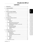
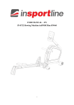
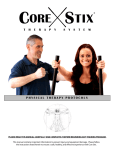
User’s Product Manual OM Edition 3 LifeCore LC-985VGS Elliptical Introduction Congratulations on your purchase of the LC-985VGS elliptical. This product has been designed and manufactured to meet the needs and requirements for domestic use. By choosing the 985VG elliptical, you have made a wise decision which will improve your health as well as your families. Being fit and healthy will improve your energy level and your quality of life. Cardiovascular training is vital for all ages and the LC-985VGS elliptical provides a more effective workout, producing better results, and will encourage you to reach your fitness goals and maintain the body you have always wanted. In order to make your experience with LifeCORE the best it can be, please review the enclosed user’s manual prior to assembly and first use. Be sure to keep the instructions for reference and/or maintenance. We also offer a complete line of fitness equipment; please take a moment to review our other excellent products at www.LifeCOREfitness.com. Should you have any questions, please contact us. Your feedback and ideas about your experience with LifeCORE are also very important to us. Please write to us at: LifeCORE Fitness Inc. 2575 Pioneer Ave. Suite 101 Vista, CA 92081 We wish you lots of success and fun while training! Purchaser’s Reference Information Serial Number is located on the frame Please send in the attached warranty card and a copy of the original receipt or register online at www.lifecorefitness.com within (10) days of purchase to register your product with LifeCore Fitness. Page | 1 Table of Contents Introduction……………………………………………………………………………………............. 1 Purchaser’s Reference Information …………………………………………………………………. 1 Table of Contents……………………………………………………………………………………… 2 Safety instructions and Warnings……………………………………………………………………. 3 Assembly Instructions………………………………………………………………………………… 4 Setting Up Your Elliptical ……………………………………………………………………………. 7 Correct Exercising Guide ………………………………………………………………………….... 9 Console Operation Instructions ……………………………………………………………………… 11 Calculating Target Heart Rate ………………………………………………………………………. 17 Heart Rate Monitoring Devices……………………………………………………………………… 18 Care and Maintenance ………………………………………………………………………………. 19 Error Message Guide..………………………………………………………………………………. 19 Parts List & Parts Diagram…………………………………………………………………………… 20 Warranty Card…………………………………………………………………………………………. 22 Page | 2 Safety Instructions & Warnings The LC-985VGS elliptical is designed and manufactured to meet or exceed all domestic and international safety standards. However, certain precautions need to be followed when operating any exercise equipment. General safety instructions: 1. It is important to consult your physician before any exercise program. 2. Pregnant women should consult with their physician before beginning any exercise program. He/she can help determine the exercise program that is the most appropriate for your age and physical condition. 3. If you experience dizziness, nausea, chest pains or other abnormal symptoms during exercise, stop the exercise session immediately. Consult your physician before continuing your exercise. 4. Keep children away from the equipment. Hands and feet may get caught in the pedals or other moving parts, which could result in serious injury. 5. No more than one person should ever use the product at a time. 6. Pets should never be allowed near unit. 7. Always wear proper clothing and shoes when exercising. Drink plenty of fluids when exercising. 8. Always stretch and warm up before starting any exercise program. 9. Never operate this unit if it is damaged or broken. Contact your authorized dealer for service. 10. Place your equipment on a solid, level surface when in use. 11. Place your unit in an area with enough clearance to operate the equipment. 12. Make sure all components are fastened securely at all times. 1. 2. 3. 4. 5. 6. 7. 8. 9. 10. 11. 12. Product safety instructions: Start your exercise program gradually. Exercise only for a few minutes the first day to let your body adjust to the new exercise. Slowly increase your exercise time and intensity over the first two weeks. If you increase your intensity too rapidly, or fail to warm up properly, you can increase the risk of injury. Use of this machine with worn or weakened parts, may result in injury to the user. We strongly suggest replacing it immediately. Use only the accessory attachments recommended by the manufacturer. Unit maximum weight limit is 300LBS It is recommended the unit be plugged into a surge protector. Do not place machine in an area of high voltage or electromagnetic fields. Whenever mounting or dismounting from the exercise machine, make sure that the unit is not in motion and use caution to prevent injury. Use the handlebars or a helper whenever additional stability is required. Make sure that all components are fastened securely including but not limited to seat, pedals, handlebars, or any electric components. Never place any open containers of any type directly on the unit, only containers with lids are recommended to be used with the appropriate water bottle holder. Keep machine clear of any obstructions, heavy machinery, and never place objects on or against machine. DANGER: Always unplug the power cord before performing maintenance. Failure to follow these instructions will void the units warranty and the manufacturer or distributor assumes no responsibility for personal injury or property damages related to the product if unit is ever used incorrectly or for reasons other than exercise. Perform proper maintenance as recommended in this manual. Page | 3 Assembly Instructions Before assembling your product, distinguish a proper and appropriate location for the unit where there is easy access to an electrical outlet with a surge protector. Clear a big enough working space before unpacking your LC-985VG Elliptical. A. Assemble the rear stabilizer tube (003) with the same 2 bolts (308) and 2 washers (403), tighten bolts firm. Remove the rear polystyrene packaging from under the unit. Step 1: Unpackaging A. Using a knife, gently open the carton and cut the sides so it lays flat on the floor as illustrated below. Unpackaged all loose components. Double check the packing Stepmaterials 4: to ensure no missing parts were left behind. Step 5: Upright Tube Assembly Note: For SAFETY REASONS: Additional assistance may be needed to help lift upright tube onto main frame assembly. A. Remove the front polystyrene packaging. Step 3: Rear Stabilizer Tube Assembly Note: For SAFETY REASONS: Additional assistance may be needed to help lift main frame assembly. Tools Needed: 14mm wrench B. Remove the rear polystyrene packaging and lift the rear of the machine off the floor. Slide the packaging under the rear end of the machine as illustrated below. Note: Make sure that all wires are connected together properly, and cover (111) is on upright tube before positioning upright tube. B. As illustrated below, connect computer cable (703) to motor with cable wire (701). Make sure wires are connected together properly. With assistance from another person, carefully lift the upright tube (004) and slide the upright tube into the main frame (001). Push and store excess wires back into the upright tube (004). Be careful not to pinch the wires. C. With the rear end of the machine now raised off the floor; use a 14mm wrench to undo Qty. 2 bolts (308) and Qty. 2 washers (403). Discard the red transportation tube. Page | 4 Step 6: Upright Tube Assembly Tools Required: 6mm Allan wrench B. Assemble the front stabilizer tube (002) with the same 2 bolts (308) and 2 washers (403), tighten bolts firm. C. Remove the polystyrene block and discard. A. Locate hardware bags labeled (Part: #302 bolt (M8x15) & #401 washers (M8x19x1.5) As illustrated below, lift up cover (111) and assemble Qty. 6 bolts (302) and washers (401) into main frame (001). If needed, rotate the foot pedal tubes (011 & 012) for easier access to side bolts. Using a 6mm Allen wrench, firmly tighten the 6 Allen bolts. D. Using a Philips screw driver, remove preinstalled Qty. 2 screw (301) from upright tube (004). Align water bottle holder (141) and fasten with the same 2 screws. B. Slide hat cover (111) into position. Step 9: Stationary Handle Bar Assembly Tools Needed: 6mm Allan wrench Step 7: Front Stabilizer Assembly Tools Needed: 14mm wrench Philips screw driver A. Place a polystyrene block under front of unit, now with the front of the machine raised off the floor; use a 14mm wrench to undo Qty. 2 bolts (308) and Qty. 2 washers (403). Discard the red transportation tube. A. Located stationary handle bar (013) and loosen preassembled Qty bolts (302) and Qty. 3 washers (401). Feed both the computer cable (703) and hand pulse cable (733) out through the top of the stationary handle bar (013). Slide the stationary handle bar into the upright tube (004). B. Secure stationary handle bar with the same Qty. 3 bolts (302) and 3 washers (401) previously removed. Use a 6mm Allan wrench to tighten bolts firm. Page | 5 Step 10: Adjustable Foot Pedal Assembly Step 12: Computer Assembly A. As illustrated below, locate and slide the adjustable foot pedals (115) onto the left and right foot pedal tubes (011 & 012). Locate and tighten foot pedal knobs (116) to the adjustable foot pedals to firmly secure them in place. Note: The adjustable foot pedals can be adjusted to your personal preference; however, we suggest starting with the middle setting number 3. Tools Needed: Philips screw driver A. Locate computer console (716) and connect computer cable (703) and hand pulse cable (733) to the computer. B. Feed the excess cables back in the stationary handle bar (013). Be careful not to pinch wires. C. Unscrew Qty. 4 computer screws from the back of the console, and fix the console to the top of the stationary handle bar (013). Using a Philips screw driver, tighten the Qty. 4 computer screws to console firm. Step 11: Dual Action Handle Bar Assembly Tools Needed: 13mm wrench A. As illustrated below, slide the top pivot covers (146) to the dual action handles (007) & (008). Step 13: Power Cord Assembly B. Insert the dual action handles (007 & 008) into the top of dual action arm (005 & 006) Note: Left and Right stickers on handle bars. C. Locate hardware bags and secure with Qty. 4 bolts (306), Qty. 4 washers (401) and Qty. 4 nuts (200). Using a 13mm wrench, tighten nuts firm. Slide top pivot covers over hardware. A. Attach the AC adaptor jacket into the power socket on the main frame before plugging the power cord plug into the wall outlet. Turn the AC power switch on. Flip the ON/OFF switch to the ON position. "0" sign is for OFF; "I" sign is for ON. Page | 6 Setting Up Your Elliptical Height Adjuster Cap Important: Make sure that the LC-985VGS is always positioned in a location that has a solid level floor. It is recommended that if this elliptical is being placed on a hardwood, tile or any delicate surface that a protective mat is placed under the machine to help prevent damaged to the machine and/or damage to the flooring surface. Please contact your dealer to purchase a compatible mat for this machine. 1) To stabilize your elliptical, first make sure the left and right front stabilizer wheel caps (112 & 113) are touching the ground. 2) Determine which side of the machine is unstable. Using the rear stabilizer caps (119) in the back of the machine, adjust the dial clockwise (lower) or counter-clock wise (Lift) to help lift or lower the back of the machine to stabilize it. Foot pedal Adjustment 1) To adjust the foot pedals, simply loosen Qty. 2 foot pedal knobs (116) on each side of the foot pedals. 2) Slide the adjustable foot pedals (115) to the desired setting using the number labels as a guide. (1-5) Slide the edge of the adjustable foot pedal to the gray line of desired number. Note: To prevent injury, make sure that each foot pedal is adjusted to the same number. 3) Retighten foot pedal knobs (116) firmly on both sides of the adjustable foot pedal. Page | 7 Foot Pedal Position The elliptical foot pedals are extra long allowing variable foot positions depending on your preference. The further back your feet are on the foot pedal, the greater the vertical height of the elliptical motion and the harder the workout. The closer forward your feet are on the foot pedal, the smaller the vertical height of the elliptical motion and easier the workout. Adjusting the foot pedals to numbers 1, 2 will position the foot pedal forward on foot pedals working more of the front of the legs. Positioning the foot pedal to the number 3 position puts the foot pedals in the most neutral position, allowing for an overall muscle workout. Adjusting the foot pedals to 4, 5 will position the foot pedal back on the pedals working more of the back of the legs. Begin with your feet in the most forward position at setting position 3. As you progress, move your feet to the position that feels most comfortable and best suits your capabilities. Slowly adjust the foot pedals to different numbers as your workouts improve. Stationary Handel Bar and Dual Action Handlebars Stationary Handle bars The 985VG elliptical comes with two dual pulse sensors on the stationary handlebar. These sensors are positioned at two different locations to help users hold on to different positions during their workouts. Firmly grasp the pulse sensors to allow the computer to register your pulse on the display window. Important: Always hold on to the stationary handlebar when getting ON and OFF of the unit for added stability. Dual Action Handlebars The dual action handle bars allows a user to work the upper body during a workout. Grasp the dual action handle bar at the most natural and comfortable position. As your right foot moves forward so will your right arm and vice versa. Push on the handles to help accelerate your motion during workouts. Page | 8 Transportation & Storage 1) Make sure that the dual action arms (007 & 008) are parallel with one another or one foot pedal is at the top of elliptical disk and other at the bottom. 12 and 6 o’clock positions. 2) Grasp the front of the stationary handle bar (013) with both hands and pull back (towards you), tipping the machine allowing the back to be in the air as illustrated below. 3) Once the machine is balanced on the wheels, wheel the machine to desired location. After the move, gently set the machine down at its new location and adjust the levelers on the bottom rear of stabilizer tube to stabilize the machine if needed. (Page 7) WARNING: Never attempt to lift or move the 985VG by yourself, ask for additional help if needed and never attempt to lift the machine if you have any medical issues. Correct Exercise Guide Getting on Safely Important: Never attempt to get on to the machine while in motion. Always take care when getting ON or OFF your Elliptical. Please follow the correct procedure below. 1) 2) 3) 4) 5) 6) When getting on machine, ensure that the left or right foot pedal is in the lowest position. Grasp the stationary handle bar with both hands. Place your left or right foot on the lowest foot pedal first. (Never the highest foot pedal) Once secure, lift your other foot over the machine and place on to opposite foot pedal. Get balanced, set up programming and begin your workout. Use the reverse procedure to get off of unit. Page | 9 Correct Position Always try and use the elliptical in a rhythmical and smooth motion. Your body should be in an upright position so that your back is straight. Keep your head up to minimize neck and upper back strain. 1. Forward & Reverse Motion The elliptical can be used in a forward or reverse motion. When going in reverse, bend your knees inwards slightly as this will put more emphasis on the buttocks and hamstrings. 2. Basic Upright Motion Handlebar: Use the stationary or dual action Muscles Used: Quadriceps, Calf, Hamstring, Glutes, and Upper body This position utilizes all the major muscle groups more evenly. Keep your body in an upright position with your back straight and head up, use the dual action arms to help utilize the upper body. 3. Lean Forward Motion Handlebar: Stationary Muscles Used: Quadriceps and Calf Leaning forward on the Elliptical, concentrates the workout more on the front of the legs and on your and calves. 4. Lean Back Motion Handlebar: stationary Muscles Used: Hamstring, Glutes Leaning back in a sitting position concentrates the workout more on the rear of the legs. Page | 10 Console Operation Instructions Please read the console operating instruction thoroughly and familiarize yourself with the console layout before choosing a workout. Going through the console first will give you ideas to the type of workout possibilities you can choose from. Below is the console layout and detailed operation instructions. Make sure the 985VG is powered-up before you start using this console. This product is powered by AC power; please make sure the power cord is properly plugged into the machine and wall outlet. Turn the AC power switch to the ON position. 1. CONSOLE LAYOUT Dot Matrix Profile Window Message Display Window Data Display Windows Big Data Display Windows Program Profiles Function Keys Page | 11 2. DISPLAYS When powering the 985VG for the first time, you can set the current time (24:00 clock) and date. This information will be stored in the console and displayed during “sleep mode”. The console will prompt you through the setting process; use UP/DOWN knob to adjust the settings and press ENTER to confirm. Dot Matrix Profile Window: Displays program profile during program setting and executing. The program profile will be different depending on which program is selected. There are 20 columns of LCD representing 20 segments of time; each time segment will represent or equal = total program time divided by the 20 columns. During a workout, a column of LCD will blink to indicate the time segment you are currently in during that point in time. There are also 16 rows of LCD representing 16 levels of resistance. Each LCD row represents 1 level of resistance and during a workout; a column(s) of LCD will blink to indicate the resistance level you are currently in during that point in time. The appropriated row of LCD will light up when you adjust the resistance level. A. Data Display Windows: There are 6 data display windows displaying time, speed/RPM, distance, calories, watt and pulse. While setting up a program, the appropriated data window will blink to indicate which data you are currently setting. Rotate the UP/DOWN adjustment dial to adjust the value and press the ENTER key to confirm the value. I. Note: Setting a number other than 0 in those display windows will count the number down. If data display setting is set at 0, the reading will count up. Note: Display sleep mode: If user stops pedaling for 4 minutes, the display will shut down and enter a “sleep mode.” Previous activities will be stored. To resume, simply press a button on the console or pedal again. B. Big Data Window: All of above data will be displayed in this window also in a bigger format. It displays one at a time for few seconds before switch to the next one. 3. Function Keys: There are 5 function keys for program operation. A. START/STOP Key: Pressing the START/STOP key once will start the program and all data will begin to count. Press the START/STOP key again to stop the computer program. To resume, simply press START/STOP one more time to start program. B. RESET Key: When program time is not counting, press the RESET key once to reset the computer back to the beginning of a program selection. All previous recorded value such as: time, distance, calories and pulse will be reset to 0, unless a user specifically entered a data value in the data display window prior to starting a program. To reset the data value in a display window, simply go back into a program and press enter until you reach the display window you want to change. Use the adjustment dial to adjust the value, next press enter then reset to clear. Pressing and holding the RESET key for 2 seconds will activate a total reset returning a user back to user profile selection. Page | 12 C. ENTER Key: Press ENTER key to confirm the program setting, selection or data entry. D. UP/DOWN Knob: Rotate the UP/DOWN dial to scroll through programs or user selections. Rotating the dial clockwise can increase the value for user data settings or to increase the resistance level during a workout. Rotating the dial counter-clockwise can decrease the value for user data settings or decrease the resistance level during a workout. E. RECOVERY Key: This is a function designed to see how much time it takes for the heart to recover after a workout and therefore recommends a fitness level. The program will take 60 seconds to figure out your fitness level and present a fitness score. Note: A heart rate pulse has to be read before and during for this function to work. Press the RECOVERY key after a workout, the time display will start counting down from 60 seconds and pulse display will display your current heart rate. Do not press any key or exercise during the 60 second period. After 60 seconds, the dot matrix display will show your fitness score. Fitness Level vs. Score Chart Score F1 F2 F3 F4 F5 F6 4. Fitness Level Excellent Good Fit Average Below Average Challenge PROGRAMS A. User profile: Before picking a program, it is recommended to set up your user profile. It will ensure workout data calculations are more accurate and future workouts are more convenient. There are four user spaces U1 – U4 to save user information, there is one profile for each user who will be using the machine. User profile information such as sex, age, height, and weight information will be saved permanently in each profile unless a user changes them. Setting Up User Profiles: Step 1: Select User Number: Power up the console or hold the reset button for a few seconds to enter user profiles. Rotate the adjustment dial to select a user profile. Dot matrix profile will show the selected user profile number, such as U1. Press the ENTER key to confirm selected user. Step 2: Setup User Gender: Male or female symbol will light up. Rotate the adjustment dial to change selection and press the ENTER key to confirm selected sex. Step 3: Setup User Age: Default reading of 25 years of age or last entered age will appear on the dot matrix window. Rotate the adjustment dial to adjust the age and press the ENTER key to confirm selected age. The range of age is 1-99 years. Step 4: Setup User Height: Default reading of 60 inches or last entered height will appear on the dot matrix window. Rotate the adjustment dial to adjust the height and press the ENTER key to confirm selected height. The range of height is 40 – 80 Inches. Page | 13 Step 5: Setup User Weight: Default reading of 100 lbs or last entered weight will appear on the dot matrix window. Rotate the adjustment dial to adjust the weight and press the ENTER key to confirm selected weight. The range of weight is 40 – 350lbs. After weight is selected, the user profile setup is complete and user information will be saved into selected user number permanently. To change the user information, simply go through the setup process and enter a different value. B. Program Category Select: After user profile is setup, choose a program category that you would like to exercise with. There are 5 categories of programs: Manual, Program P1-P12, H.R.C., User & Watt. Rotate the adjustment dial to toggle thru the different program category and press the ENTER key to confirm. To go back to the program category selection mode, simply press the RESET key once; the console will reset back to program selection mode. C. Manual Program: After user profile is set, the manual program will light up. Press the enter key if this is the program you want to select; if not, rotate the adjustment dial to the desired program. I. Quick Start: If you press the START/STOP once after you enter the manual program, time and data display windows will start to count and you can exercise immediately. Simply start pedaling and rotate the adjustment dial to adjust resistance level. II. Manual Program: If you press the ENTER key to confirm manual program selection, the next step is to setup load/ (resistance) level. Dot matrix profile will light up one row and Load display will flash a 1; rotate the adjustment dial to adjust the level from 1 to 16 and press ENTER to confirm. You can also adjust the resistance level anytime during a program. After load entry, time window will flash 00:00 or last entered time; rotate the adjustment dial to adjust the time and press ENTER to confirm. The range of time is 0:00 – 99:00 (min: sec). After time entry, the manual program setup is now complete; press the START/STOP to begin the program. Note: Manual program can also work as a goal training program for time, distance, calories or pulse. (Pulse goal will work the same as the HRC programs). For the goal training program setup; please make sure to only enter the value for the desired goal you want to achieve and enter 0 for all other values. For example, if you entered in 2.0 miles for the distance value you need to enter 0 for time, calories and pulse. The time will start counting up and the timer will stop when you reach the 2.0 mile goal. Please keep in mind, if you enter multiple values during setup, it will work as a multi goal program and whenever a goal is reached, the timer will stop. Page | 14 D. Programs (Preset Profile Programs): After you enter the program category; the 1st program: P1 will be scrolling on the dot matrix window. Rotate the UP/DOWN knob to move through the 12 preset programs, refer to program graphic below or the main display on the console for profile details. Press ENTER to confirm the profile. Programs P1 – P12: After you selected a desired profile; the next step is selecting a profile difficulty level. The dot matrix profile window will display the profile and big data window will light up appropriated level; rotate the UP/DOWN knob to adjust the level and ENTER to confirm. After level entry, time window will flash with 0:00 or last entered time for adjustment. After time entry, the program set up is now completed; press START/STOP to begin this program. E. H.R.C. program: H.R.C. programs are based off of user profile information (AGE). Heart rate control programs are designed to keep you training at your chosen heart rate level. The console will adjust the resistance level automatically to ensure the target heart rate is achieved and maintained during the entire program. Your target heart rate, the intensity needed to improve cardiovascular fitness, depends primarily on your age and not your state of fitness. It is calculated as a percentage of your maximum heart rate, estimated as 220 minus your age. It is most effective to train at your target heart rate between 60% and 85% of your maximum heart rate. In order to get the most accurate reading, it is recommended to enter your age before your workout. Note: A heart rate monitoring device must be used for the program to work. For better results, a chest strap is recommended for this operation. It is also important to consult your physician before performing any heart rate based training program. Note: Only a 5k heart rate transmitter will work with the 985VG. When the adjustment dial is rotated during the category selection mode and H.R.C. program category name is lit; press the ENTER key to enter H.R.C. programs. Enter your age and then press enter. Rotate the adjustment dial to toggle through the 4 H.R.C. programs. The dot matrix profile will show the selected H.R.C. program: 55%, 75%, 90% or TAG. Press ENTER to confirm the program. Example: 220 - (Age 45) = 175 X multiplied by (55% or 75% or 90%) (Percentage 55%) = 96 bpm Check page 17 for further assistance Page | 15 I. (TAG) Target Heart Rate Program: Press the ENTER key to select the TAG program; then setup your own heart rate goal. The pulse window will blink with the pulse value. Rotate the adjustment dial to adjust the value and press ENTER to confirm. The range of pulse which can be selected is 30 – 240 bpm. After pulse entry, time window will flash with 0:00 or last entered time. Rotate the adjustment dial to adjust the time and press ENTER to confirm. After time entry, the program setup is now complete. Press START/STOP to begin this program. II. 55%; 75% & 90% Max Heart Rate Program: As previously mentioned, a users max heart rate is equal to = 220 – age; 55%, 75% and 90% programs are based off of your user profile setting (age), and when you enter into this program the heart rate percentage will automatically be calculated. The calculated heart rate will be displayed in the pulse window. Rotate the adjustment dial till the desired percentage program is lit. Press the ENTER key to select one of these three programs; the next step is setting up program time. Time window will flash with 0:00 or last entered time. Rotate the adjustment dial to adjust the time and press ENTER to confirm. After time entry, the program set up is now complete. Press START/STOP to begin this program. F. User Profile Program: This program “custom program” is designed for users to build their own program profile segment by segment (1-20) resistance change before exercising. When the adjustment dial is rotated during category selection mode and user program name is lit; pressing the ENTER key will confirm the user setting program. The 1st segment LCD on the dot matrix window will start to blink. Rotate the adjustment dial to adjust the resistance level. Pressing the ENTER key will confirm selection, entering you into the next segment until the 20th column is reached. You may press and hold the ENTER key for 2 seconds to bypass the rest of the profile settings to enter time. Note: The remaining segments will start with resistance level 1. After all segments are completed, you will be prompted to setup the time goal before starting a workout. Press the START/STOP key anytime to start the program. G. WATT Program (constant power program): Watt (power) is determined by speed & resistance. This program is designed to let you set up your watt goal. The console will automatically adjust the resistance level according to your speed to maintain your watt goal. When the adjustment dial is rotated during category selection mode and WATT program name is displayed, press the ENTER key to confirm the WATT program. If you press the ENTER key to select the WATT program, the next step is setting up your watt goal. The watt window will flash 120; rotate the adjustment dial to adjust the value and press the ENTER key to confirm. The range of watt is 10 – 350 and can only be adjusted in decimals of 5. After watt entry, time window will flash with 0:00 or last entered time; rotate the adjustment dial to adjust the time and press ENTER to confirm. After time entry, the program setup is now complete; press the START/STOP to begin this program. Page | 16 Calculating Target Heart Rate In order to obtain the greatest cardiovascular benefits from your exercise workout, it is important to work within your target heart rate zone. The American Heart Association defines this target as 60%85% percent of your maximum heart rate. Your maximum heart rate may be roughly calculated by subtracting your age from 220. Your maximum heart rate and aerobic capacity naturally decreases as you age. This will vary from one person to another. Use this number to find your approximate effective target zone. It is most effective to train at your target heart rate between 60% and 85% of your maximum heart rate; referred to as “Training Zone”. In order to get the most accurate reading, it is recommended to enter your age before your workout. Before beginning your workout, check your normal resting heart rate. Place your fingers lightly against your neck or against your wrist over the main artery. After finding your pulse, count the number of beats in 10 seconds. Multiply the number of beats by six to determine your resting pulse rate per minute. We recommend taking your heart rate at these times; at rest, after warming up, during your workout and two minutes into your cool down, to accurately track your progress as it relates to better fitness. During your first several months of exercising, the AHA recommends aiming for the lower part of the target heart rate zone-60%, then gradually progressing up to 75%. According to the AHA, exercising above 85% of your maximum heart rate may be too strenuous unless you are in top physical condition. Exercising below 60% of your maximum will result in minimal cardiovascular conditioning. Check your pulse recovery rate – If your pulse is over 100bpm five minutes after you stop exercising, or if it’s higher than normal the morning after exercising, your exertion may have been too strenuous for your current fitness level. Rest and reduce the intensity level of the next exercise. Fitness Safety: The Heart Rate chart indicates average heart rate zones for different ages. A variety of different factors (including medication, emotional state, temperature and other conditions) can affect the target heart rate zone that is best for you. Your physician or health care professional can help you determine the exercise intensity that is appropriate for your age and condition. Page | 17 Heart Rate Monitoring Devices Pulse Hand Grips (Standard) The 985VG comes standard with stainless steel pulse handgrips. To activate, gently grasp both handgrips to obtain a heart rate reading. Hold on to the hand grip for a few seconds until the computer is able to calculate your pulse and get a steady reading. Once you let go of the hand grips the computer will need to recalculate your pulse. Note: It is recommended to wear a chest strap for the Heart Rate control programs, as it is more accurate and will constantly transmit a signal to the computer. If you wear a chest strap and use the steel pulse hand grips at the same time, please note the console will take the measurement of the chest strap over the hand pulse. Operating Tips: If you are not getting a consistent reading while using the hand pulse option, we recommend the following suggestions: • Make sure that the palms of the hands are touching the contact area of each hand pulse grip. • Maintain an even pressure on the grips. • Do not hold the hand pulse grips too tightly. • In some cases dampening your palms may help the sensors register a more stable heart rate. Chest Strap (Optional) The 985VG is equipped with a built-in wireless 5k receiver for your heart rate monitoring transmitter. Please contact your dealer to purchase a compatible 5k chest strap transmitter, if you would like to use more wireless heart rate features. To get an accurate reading using these devices, you will need to be within three feet of the console, and a minimum of four feet from others using a heart rate monitoring device. The receiver of the wireless ECG system is built into the console unit. How to Wear Your Sensor/ Transmitter: (1) (2) (3) (4) (5) Buckle one end of the chest strap onto the transmitter. Adjust the band length so that the fit is snug, but not too tight. Buckle the other end of the chest strap onto the transmitter Center the transmitter on your chest below the pectoral muscle (breasts). Stretch the transmitter away from your chest and moisten the conductive electrode strips located next to the buckles with water. Note: The transmitter is on automatically when it is being worn. It is off when it is not connected to your body; however, as moisture may activate the transmitter, thoroughly dry the transmitter after every use to prolong battery life. Page | 18 Care and Maintenance The LifeCORE 985VG is made from the best materials and has been tested and received a quality control review prior to its packaging to ensure the correct parts and proper fitting of each component. This machine was designed to limit the amount of assembly needed by a customer. The amount of maintenance required is very little and very simple; however, a failure to implement preventative maintenance suggestions can prevent the machine from operating as designed. The 985VG is only for indoor use and should not be stored outside or damp, extremely cold or hot areas as this will damage the unit voiding the warranty. Rules: Never use WD-40 or any type of silicone spray to lubricate any moving parts. Use of this type of lubricating will damage the unit’s components voiding the warranty. Use only appropriate lithium assembly grease as needed to the pivot points if noise occurs. Contact Lifecore to find out exactly what type of grease is acceptable or to purchase grease. Always clean the machine after use. 1) Proper cleaning is important for longevity of a machine, clean the unit with a light soap water mixture, followed by a dry towel. You can also use a light house hold cleaner such as Windex to remove dirt and sweat. The purpose of cleaning the unit is to remove body sweat from the unit which contains salt. Salt is the number one factor that will cause the unit to rust and the electronics to stop working. 2) Dry the unit off with a clean towel to remove left over moisture after every use. After the first 12 hours of use, check and retighten any bolts, nuts, screws, pedals, etc. making sure that they are tight and working properly. 1) The number one service issue is loose hardware. Loose hardware can cause the unit to tick, creak, thump, knock, etc. After the first 12 hours once all the hardware has been tightened, the hardware should be checked every 3 months. (dual action handle bar, stationary handle bar, foot pedals, stabilizers) 2) Greasing the 3 Pivot Points: Greasing the pivot points will help to maintain a smooth and quite machine. If you wish to grease the 3 Pivot Points, use lithium grease that is friendly to plastic (some greases can destroys plastic). Disconnect the foot pedal tube and the dual action arms, and evenly apply a finger tip amount of grease to the moving parts and reassemble. This service is recommended every year. Only use the appropriate 9V 1000mA power source, never use an adapter that is not certified for the unit, a wrong adapter will cause the electronics to overheat and malfunction voiding the warranty. Error Message Guide If the computer detects an error, it will display the text “E2”. If the following solutions fail to correct the problem, then contact your dealer for assistance. Problem: No motor detected software failure. Solution: Reconnect all cable plug connections, refer to assembly instructions. Reboot the computer. Disconnect the power for approximately 15 seconds by disconnect the plug-in adapter. In the unlikely event that the 985VG experiences a problem, please contact LifeCORE fitness for advice toll free at 888-815-5559. Page | 19 Parts List & Parts Diagram Page | 20 Page | 21 Warranty Card Limited Consumer Warranty LifeCORE Fitness Inc. LC-985VGS Elliptical What is Covered. LifeCORE Fitness, Inc. (“LifeCORE”) warrants to the original purchaser of this LifeCORE Fitness branded product (the “Product”) that the frame of the Product shall be free from defect in materials and workmanship during the normal life of the Product and all other part and components of the Product shall be free from defect in material and workmanship for a period of 2 years when the Product is used under as recommended by LifeCORE under normal family household uses and conditions. During the warranty period LifeCORE will at no additional charge to you, repair or replace (at LifeCORE option) the frame or any part of the Product if it becomes defective, malfunctions, or otherwise fails to conform with this Limited Warranty. All labor shall be the responsibility of the owner. What is Not Covered. This Limited Warranty applies only for Product sold in the United States under the LifeCORE brand name. This warranty does not cover normal wear and tear on items such as, but not limited to, transportation wheels, foot pedals, rubber grips, plastic end caps, scratched parts, broken covers, cosmetic damage, and excludes paint & finish. Wear items pertain to components that might need to be replaced due to wear and tear resulting from normal usage. This warranty is void if the Produce is improperly stored, installed, altered and/or modified in any way, misused, abused, is subject to accident, is improperly maintained, and this warranty does not cover repair for any noises such as: squeaks, clunks, thumps resulting from poor or lack of preventive maintenance. This Limited Warranty does extent to any Product that is damaged or rendered defective; (a) as a result of accident, misuse, or abuse; (b) use with the Product of any part not manufactured or sold by LifeCORE; (c) by modification of the Product; (d) by normal wear and tear; (e) operation using incorrect power supplies; or (f) as a result of service by anyone other than LifeCORE, or an authorized LifeCORE service provider. This Limited Warranty is void if the Product serial number has been defaced or removed. Should any Product be submitted for warranty service be found ineligible, an estimate of repair cost will be furnished. Warranty Service Area. It is the purchaser’s sole responsibility to pay for any fees associated with servicing of a product. Any evidence of alteration, erasing or forgery of proof-of-purchase documents voids this Limited Warranty. This Limited Warranty applies only to Product purchased from LifeCORE or from an authorized LifeCORE reseller. Disclaimed Warranties. TO THE MAXIMUM EXTENT ALLOWED BY LAW, ALL WARRANTIES, INCLUDING BUT NOT LIMITED TO EXPRESS WARRANTY, IMPLIED WARRANTY, WARRANTY OF MERCHANTABILITY, FITNESS FOR PARTICULAR PURPOSE AND WARRANTY OF NON-INFRINGEMENT OF INTELLECTUAL PROPERTY, ARE EXPRESSLY EXCLUDED TO THE MAXIMUM EXTENT PERMITTED BY LAW; AND LIFECORE NEITHER ASSUMES NOR AUTHORIZES ANY PERSON OR ENTITY TO ASSUME FOR IT ANY DUTY, OBLIGATION OR LIABILITY IN CONNECTION WITH ITS PRODUCTS. LIFECORE HEREBY DISCLAIMS AND HAS ABSOLUTELY NO LIABILITY FOR ANY AND ALL ACTS OF THIRD PARTIES INCLUDING DEALERS OR INSTALLERS. IN THE EVENT OF A CLAIM OR A DISPUTE INVOLVING LIFECORE OR ITS SUBSIDIARY, THE PROPER VENUE SHALL BE SAN DIEGO COUNTY IN THE STATE OF CALIFORNIA. CALIFORNIA STATE LAWS AND APPLICABLE FEDERAL LAWS SHALL APPLY AND GOVERN THE DISPUTE. THE MAXIMUM RECOVERY UNDER ANY CLAIM AGAINST LIFECORE SHALL BE STRICTLY LIMITED TO THE PURCHASE PRICE OF THE PART. LIFECORE SHALL NOT BE RESPONSIBLE FOR ANY DAMAGES WHATSOEVER, INCLUDING BUT NOT LIMITED TO, ANY CONSEQUENTIAL DAMAGES, INCIDENTAL DAMAGES, DAMAGES FOR THE LOSS OF TIME, LOSS OF EARNINGS, COMMERCIAL LOSS, LOSS OF ECONOMIC OPPORTUNITY AND THE LIKE. Some states do not allow limitations on how long an implied warranty will last or the exclusion or limitation of incidental or consequential damages. This warranty gives you specific legal rights and you may also have other rights that vary from State to State. LifeCORE does not and has not authorized any person or entity to create for it any other obligation, promise, duty or obligation in connection with this Product. Warranty Registration. PLEASE SEND IN THE ATTACHED WARRANTY CARD WITHIN (10) DAYS OF PURCHASE TO REGISTER YOUR PRODUCT WITH LIFECORE FITNESS. PLEASE MAIL WARRANTY CARD TO: LIFECORE FITNESS, INC, 2575 Pioneer Ave. Suite 101. Vista, CA 92081. Phone (760)599-4555, Fax (760) 946-7602 or register online at Page | 22 LifeCOREfitness.com, Customer Service: 888-815-5559. Unless otherwise prohibited by law, in order to validate the warranty this Product must have been registered through LifeCORE Fitness Inc., and/or a copy of the proof of purchase, and serial number must be presented at time of service. If these items are not presented at the time of requesting parts or service LifeCORE Fitness Inc. will not cover any warranty. Warranty Claim Processing. To obtain warranty service, you must contact the original place of purchase. Any parts replaced under this warranty will at the time of service become the property of LifeCORE. LifeCORE reserves the right to change manufacturers of any parts to cover any existing warranty. Any parts determined to be defective must be returned to LifeCORE to obtain warranty service. You must prepay any shipping charges, export taxes, custom duties and taxes, or any other charges associated with transportation of the parts or Product. In addition, you are responsible for insuring any parts shipped or returned. You assume the risk of loss during shipment. Please see other LifeCORE Fitness Products at www.LifeCOREfitness.com. THANK YOU FOR YOUR BUSINESS! LC-985VGS Elliptical Please Attach a Copy of the Original Receipt Full Name: _______________________________________________________________________ Address: ________________________________________________________________________ City: ______________________State: ________ Zip Code: ________________________ Daytime Phone No.:_______________ Cell Phone No.:___________________________ Email: ________________________________________________________________________ Dealer Purchased from: ____________________________________________________ Model: LC-985VGS Elliptical _______________________ _________ Date Of Purchase: Serial No._____________________________________ Environment Placed: Residential Light Commercial Commercial Page | 23 Customer Service Toll Free (888) 815-5559 Mon-Friday 7:30 - 5:30 PT [email protected] Lifecore Fitness Inc. 2575 Pioneer Ave. Suite 101 Vista, CA 92081 Visit our website for assembly videos: www.lifecorefitness.com Page | 24