1
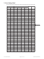
User Manual
Low Profile Small Diameter Scanner
KEEP THIS MANUAL – DO NOT LOSE
THIS MANUAL IS PART OF THE CIRC-IT SYSTEM AND MUST BE KEPT FOR THE LIFE OF
THE PRODUCT. PASS ON TO SUBSEQUENT OWNERS.
Ensure any amendments are incorporated with this document.
CAUTION! The Circ-it is designed for a specific use.
Using the Circ-it outside of its
intended use could cause damage to the product. Read and understand this manual before
using.
The WEEE symbol indicates that the product must not be disposed of as unsorted municipal
waste, but should be collected separately.
1. Specifications�����������������������������������������������������������������������������������������������������������������������3
1.1.
1.2.
1.3.
Intended Use������������������������������������������������������������������������������������������������������������������������������������������3
Performance Specifications�������������������������������������������������������������������������������������������������������������������3
Operating Environment��������������������������������������������������������������������������������������������������������������������������3
2. Preparation for Use��������������������������������������������������������������������������������������������������������������3
2.1.
2.2.
2.3.
2.4.
2.5.
2.6.
2.7.
2.8.
Items Required for Scanner Setup���������������������������������������������������������������������������������������������������������3
Scanner Component Identification���������������������������������������������������������������������������������������������������������4
Dual Probe Scanner Setup��������������������������������������������������������������������������������������������������������������������5
Single Probe Scanner Setup������������������������������������������������������������������������������������������������������������������7
Installing Probes and Wedges���������������������������������������������������������������������������������������������������������������7
Setting Wedge Spacing������������������������������������������������������������������������������������������������������������������������10
Using Wedge Separation Indicators�����������������������������������������������������������������������������������������������������10
Irrigation Lines & Probe/Encoder Connections������������������������������������������������������������������������������������12
3. Operation����������������������������������������������������������������������������������������������������������������������������12
3.1.
3.2.
General Scanner Operation�����������������������������������������������������������������������������������������������������������������12
Single-sided Access Operation������������������������������������������������������������������������������������������������������������13
4. Maintenance�����������������������������������������������������������������������������������������������������������������������14
5. Troubleshooting�����������������������������������������������������������������������������������������������������������������15
6. Spare Parts�������������������������������������������������������������������������������������������������������������������������16
7. Circ-it Setup Chart�������������������������������������������������������������������������������������������������������������17
DISTRIBUTOR:
MANUFACTURER:
Jireh Industries Ltd.
53158 Range Road 224
Ardrossan, Alberta, Canada
T8E 2K4
Phone:(780) 922-4534
Fax: (780) 922-5766
www.jireh-industries.com
Circ-it User Manual
Page 2 of 18
DJ0050.indd REV 02
1.Specifications
1.1. Intended Use
The Circ-it is a manual small diameter scanner. It is designed to provide encoded position of probes
circumferentially around piping and tubing. The pipes/tubes must be:
- free of debris, scale, soot, etc.;
- no smaller than 21.3mm (0.840’’) outer diameter;
- no larger than 114.3mm (4.500”) outer diameter.
The Circ-it is intended for both dual and single probe scanning applications.
The Circ-it is intended to operate in an environment as described in Section 1.3 “Operating Environment”.
1.2. Performance Specifications
Table 1 – General Specifications
Scanner Diameter Range
0.840” (21.4mm) – 4.50” (114.30mm)
Scanner Width*
1.98” (50mm)
Encoder Resolution
32.08 pulses/mm
Environmental Sealing
IP67
Required Radial Clearance*
0.433” (11.0mm)
* Scanner only. Transducers and wedges not included.
1.3. Operating Environment
The Circ-it is designed for use in an industrial environment that is between -40°C and 80°C.
2.Preparation for Use
2.1. Items Required for Scanner Setup
The following supplied tools are required for assembly, re-configuration, and adjustment of the scanner:
- T6 Torx Screwdriver
- Philips Head Screwdriver
- Loom Installation Tool
- Circ-it Sizing Chart
Circ-it User Manual
Page 3 of 18
DJ0050.indd REV 02
2.2. Scanner Component Identification
The Circ-it system consists of the components shown in Figure 1 - Figure 8.
Figure 1 - Scanner Assembly (laid out flat)
Figure 2 - Long Link
Figure 3 - Medium Link
Figure 4 - Short Link
Figure 5 - Wheel Block
Circ-it User Manual
Page 4 of 18
DJ0050.indd REV 02
Figure 6 - Short Latch
Figure 7 - Long Latch
Figure 8 - Irrigation Hose & Splitter
2.3. Dual Probe Scanner Setup
NOTE: Scanner setup should be carried out in a clean,
well-lit area on a flat and level work surface.
To setup the Circ-it, follow these steps:
a. Install probes and wedges (see section 2.4. Installing Probes and Wedges).
b. If desired, set probe spacing (see section 2.5. Setting Wedge Spacing).
c. Confirm tube or pipe O.D. to be scanned.
d. Use Circ-it Setup Chart (page 17) to determine link and pivot combination required.
e. Install links and pivots as shown (see Figure 9 - Figure 13). Alternate wheel blocks and links so
that the links are always separated by a joint (i.e. a link is never attached directly to another link).
Circ-it User Manual
Figure 9
Figure 10
Figure 12
Figure 13
Page 5 of 18
Figure 11
DJ0050.indd REV 02
f. Lower setup tab by loosening the two screws on either side of the tab (see Figure 14). After the
setup tab has been lowered, retighten the screws on either side of the tab.
Figure 14 - Lowering Setup Tab
g. Loosen pivot adjustment screws 1/8th turn to allow for adjustment (see Figure 15).
Figure 15 - Loosening Pivot Adjustment Screws
NOTE: It is not necessary to loosen pivot adjustment screws beyond 1/8th turn as doing so will
create unwanted movement in the scanner making proper setup more difficult.
h. Install scanner on an open ended tube/pipe (see Figure 16). Wrap the scanner around the tube/
pipe and connect the latch to the main scanner assembly. Before tightening pivot adjustment
screws, ensure that all wheels and both indicator points of the setup tab are contacting the tube/
pipe surface and the latch is fully engaged.
i.
Tighten pivot adjustment screws with the scanner wrapped around the tube/pipe (Figure 17).
Figure 16
j.
Figure 17
Remove scanner from tubing or pipe and place on a hard, flat surface.
k. Raise setup tab to original position (Figure 18).
Figure 18 - Raising Setup Tab
l.
Repeat process for the opposite side.
Circ-it User Manual
Page 6 of 18
DJ0050.indd REV 02
2.4. Single Probe Scanner Setup
To use the Circ-it in a single probe scanning configuration, follow these steps:
a. Loosen crossbar bracket retaining screws and slide the non-encoded side of the scanner
assembly away from the encoded side (Figure 19 - Figure 20).
Figure 19
Figure 20
b. Repeat steps a-k from section 2.3. Dual Probe Scanner Setup using the single probe scanner
assembly.
2.5. Installing Probes and Wedges
To install probes and wedges on the Circ-it, follow these steps:
a. If present, remove both chain assemblies from scanner
b. Loosen pivot adjustment screws (Figure 21) and fold scanner in hand as shown in Figure 22.
Figure 21 - Loosening Pivot Adjustment Screws
Figure 22 - Fold Scanner in Hand
c. Loosen probe holder adjustment screws (Figure 23) 1/8th turn to relieve clamp pressure. When
the probe holder arms are free to move, slide arms apart (see Figure 24).
NOTE: It is not necessary to remove probe holder arms. Be sure to only loosen and slide apart.
Figure 23
Circ-it User Manual
Figure 24
Page 7 of 18
DJ0050.indd REV 02
d. Install wedge by matching the pivot holes with the probe holder arm pivot buttons (see Figure 25
- Figure 26).
Figure 25 - Pivot Button
Figure 26 - Probe Installation
e. Center the wedge and probe holder arms as
shown in Figure 27.
f. Tighten probe holder adjustment screws.
Ensure that the wedge is free to rotate about
the pivot buttons before tightening.
g. Remove the sleeve clamp screw (Figure 28)
and slide the protective sleeving and sleeve
clamp from the scanner assembly (Figure
29). Remove the sleeve clamp and protective
sleeving from the irrigation tube and encoder
cable (encoded side only) if applicable.
Figure 28
Figure 27
Figure 29
h. Insert the irrigation tube, encoder cable (encoded side only), and probe cable in the cable
management clip (Figure 30) and run cable/tube bundle through the sleeve clamp bracket
(Figure 31).
Figure 30
Circ-it User Manual
Figure 31
Page 8 of 18
DJ0050.indd REV 02
i.
Use the loom installation tool to install the protective sleeving over the cable/tube bundle. To do
this, start at the scanner end and follow these steps:
i.
Close the tool over the bundle with the pointed shoe portion pointing away from the scanner.
ii. Slide the protective sleeving over the pointed shoe portion of the tool so that it spreads open,
follows the tool, and starts to wrap itself around the bundle.
iii. While holding the portion of the protective sleeving that is already around the bundle, slide
the tool away from the scanner so that the remainder of the protective sleeving wraps around
the bundle.
j.
Figure 32
Figure 33
Figure 34
Figure 35
Re-install the sleeve clamp over the cable/tube bundle (Figure 36) and slide it over the protective
sleeving as shown in Figure 37 (be aware of the clamp orientation). Install the sleeve clamp
screw so the threads just start to engage in the sleeve clamp.
k. Slide the protective sleeving over the sleeve clamp bracket on the scanner assembly. Work the
sleeve clamp into position and tighten the sleeve clamp screw until sufficiently snug. Ensure the
sleeve clamp is oriented so that the sleeve clamp screw will not protrude lower than the scanner
wheels and rub on the inspection surface (see Figure 38).
NOTE: Do not over tighten sleeve clamp screw. Over tightening will cause screw to break.
Figure 36
l.
Figure 37
Figure 38
Repeat process for the opposite side
Circ-it User Manual
Page 9 of 18
DJ0050.indd REV 02
2.6. Setting Wedge Spacing
To set the wedge spacing, follow these steps:
a. If present, remove both chain assemblies from scanner
b. If wedges are not installed, proceed to section 2.5. Installing Probes and Wedges
c. Loosen pivot adjustment screws (Figure 39) and push scanner against a flat surface (Figure 40)
Figure 39 - Loosening Pivot Adjustment Screws
Figure 40
d. Loosen both crossbar clamp screws (Figure 41) located on the non-encoded side of the scanner
Figure 41 - Loosening Crossbar Clamp Screws
e. Slide encoded and non-encoded chain to desired separation and tighten the crossbar clamp
screws
2.7. Using Wedge Separation Indicators
To use the wedge separation indicators to set wedge spacing, follow these steps:
a. If present, remove both chain assemblies from scanner
b. If wedges are not installed, proceed to section 2.5. Installing Probes and Wedges
c. Loosen pivot adjustment screws (Figure 39) and push scanner against a flat surface (Figure 40)
d. Loosen both crossbar clamp screws (Figure 41) located on the non-encoded side of the scanner
e. Slide the wedges together till they make contact with each other (Figure 42)
Figure 42
Circ-it User Manual
Page 10 of 18
DJ0050.indd REV 02
f. Loosen the indicator clamp screws (Figure 43).
Figure 43
g. Slide the indicator to the non-encoded side of the scanner (Figure 44).
Figure 44
h. Tighten the indicator clamp screws.
i.
Slide the chains apart till desired wedge separation is achieved. The number of graduations
between the indicator and non-encoded side of the scanner is the probe separation in mm as
shown in Figure 45.
Figure 45 - Wedge Separation Indication
j.
Tighten both crossbar clamp screws.
Circ-it User Manual
Page 11 of 18
DJ0050.indd REV 02
2.8. Irrigation Lines & Probe/Encoder Connections
Use the following diagram to assist in connecting the irrigation lines and probe/encoder cables:
Figure 46 - Connecting irrigation lines and probe/encoder cables
3.Operation
3.1. General Scanner Operation
For scanner operation with access to all sides of pipe/tube to be scanned, follow these steps:
a. Place scanner assembly with attached chain around pipe/tube.
b. Lift latch on the end of the chain (Figure 47) and pull toward scanner assembly (Figure 48).
c. Allow latch to ‘click’ into place in the tightest notch possible (Figure 49). Ensure that proper probe
contact is made with scanning surface. If probe contact is not adequate, see Section 2.3. Dual
Probe Scanner Setup to re-adjust scanner assembly.
Figure 47
Circ-it User Manual
Figure 48
Page 12 of 18
Figure 49
DJ0050.indd REV 02
d. Pivot latch into flat position before initiating scan (Figure 50 - Figure 51).
Figure 50
Figure 51
3.2. Single-sided Access Operation
To configure the Circ-it for applications where access to pipe/tube is single-sided, use the supplied
installation hook tool and the following sequence of photos to assemble the scanner:
Circ-it User Manual
Figure 52
Figure 53
Figure 54
Figure 55
Figure 56
Figure 57
Page 13 of 18
DJ0050.indd REV 02
Figure 58
Figure 59
Figure 60
Figure 61
Figure 62
Figure 63 - Ready for scan
4.Maintenance
Wipe the scanner clean as required. Do not soak or submerse the scanner in cleaner or solvent of any
kind.
Circ-it User Manual
Page 14 of 18
DJ0050.indd REV 02
5.Troubleshooting
Problem
Possible Cause
1. Chain is too loose/
tight
Incorrect number or
Refer to the Circ-it Setup Chart (page 17)
combination of links for proper for required number of links for the diameter of
scanner configuration.
pipe/tube you are scanning. Remember to use
the Outer Diameter measurement of your pipe/
tube. Re-setup the scanner with the correct
number of links. See section 2.3.
2. Insufficient probe
contact.
Solution
Incorrect latch setting.
There are two notches on the short and long
latches. Ensure that the latch is on the tightest
notch possible after the correct number of links
are used.
Incorrect latch used.
Refer to the Circ-it Setup Chart (page 17)
for proper latch (Short or Long) to use for the
diameter of pipe/tube you are scanning. For
pipe/tube less than 2” OD, use the short latch.
For pipe/tube greater than 2” OD, use the long
latch.
Scanner not set properly.
Reconfigure the scanner as per instructtions in
sections 2.3 or 2.4.
Pivot Adjustment Screws were Reconfigure the scanner as per instructions in
not tight enough and scanner sections 2.3 or 2.4.
spread apart upon installation
on pipe/tube.
3. Encoder cable clip
rubbing on tube/pipe
Circ-it User Manual
Setup tab not raised.
With the scanner removed from the pipe/
tube, raise the setup tab by loosening the two
screws on either side of the tab. There is a
setup tab on each side of the scanner. Refer
to section 2.3 or 2.4 for proper use of the setup
tab.
Tube/cables routed
incorrectly.
Refer to section 2.5 for proper probe
installation and cable management.
Incorrect pivot adjustment
and/or incorrect setup tab
adjustment.
Refer to section 2.3, specifically points f-k, to
correct the pivot adjustment and use the setup
tab for proper scanner operation. Ensure the
contact points on the setup tab are against
the pipe/tube surface before tightening pivot
adjustment screws.
Page 15 of 18
DJ0050.indd REV 02
6.Spare Parts
Refer to Figure 64 for spare parts.
Figure 64 - Spare Parts
Circ-it User Manual
Page 16 of 18
DJ0050.indd REV 02
Circ-it Setup Chart
7.Circ-it Setup Chart
Use the following chart to determine the number of links required for proper scanner setup.
Pipe/Tube OD
Link Type
Min
Max
Short
Medium
Long
Wheel
0.84
0.935
0
0
0
0
0.937
1.027
1
0
0
0
Pipe
Tube
0.840
0.875
1.000
1.022
1.111
0
0
0
1
1.111
1.199
1
0
0
1
1.050
1.196
1.283
0
0
0
2
1.282
1.367
1
0
0
2
1.365
1.451
0
0
0
3
1.375
1.449
1.533
1
0
0
3
1.500
1.532
1.617
0
0
0
4
1.614
1.698
1
0
0
4
1.698
1.781
0
0
0
5
1.125
1.315
1.315
1.660
1.750
1.779
1.862
1
0
0
5
1.862
1.945
0
0
0
6
1.942
2.025
1
0
0
6
2.013
2.153
0
1
0
5
2.142
2.28
1
2
0
4
2.272
2.409
0
3
0
4
2.383
2.521
0
2
0
6
2.500
2.508
2.644
1
3
0
5
2.500
2.636
2.772
0
4
0
5
1.900
2.000
2.250
2.375
2.762
2.893
0
1
2
4
2.875
2.878
3.011
0
3
1
5
2.875
2.994
3.124
0
0
3
4
3.113
3.244
0
2
2
5
3.234
3.368
0
4
1
6
3.342
3.473
0
1
3
5
3.466
3.598
0
3
2
6
3.569
3.7
0
0
4
5
3.694
3.826
0
2
3
6
3.798
3.929
1
0
4
6
3.92
4.051
0
1
4
6
3.995
4.126
1
1
4
6
4.117
4.249
0
2
4
6
4.192
4.324
1
2
4
6
4.314
4.446
0
3
4
6
4.415
4.547
1
1
5
6
4.538
4.67
0
2
5
6
Short Latch
Long Latch
3.000
3.250
3.500
3.500
3.750
4.000
4.000
4.500
4.500
DJ0051
Circ-it User Manual
Page 17 of 18
DJ0050.indd REV 02
Jireh Industries Ltd.
53158 Range Road 224
Ardrossan, Alberta
Canada T8E 2K4
780-922-4534
www.jireh-industries.com