1
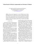
DC POWER
SUPPLY
Tenma Models 72-2005 and 72-6535
(Analog and Digital Series)
User Manual
CONTENTS
SECTION
PAGE
1. INTRODUCTION.............................................................................................................................
1
2 SPECIFICATIONS......................................................................................................................
2
.
22-2
2-3
2-4
2-5
.
3
4.
5
6
General ............................................................................................................................
2
Constant Voltage Operation ..................................................................................................
3
Constant Current Operation ................................................................................................... 3
Indicator Meter .................................................................................................................... 3
Insulation .........................................................................................................................
4
THEORY OF OPERATION ...........................................................................................................
PANEL CONTROLS AND INDICATORS...........................................................................................
4-1 Front Panel ..........................................................................................................................
4-2 Rear Panel ..........................................................................................................................
OPERATION INSTRUCTIONS......................................................................................................
5-1 Precaution.........................................................................................................................
5-2 Setting Current Limit ............................................................................................................
5-3 Constant Voltage/Constant Current Characteristic ......................................................................
5-4 Operation Mode...................................................................................................................
MAINTANCE.............................................................................................................................
6-1 Fuse Replacement .............................................................................................................
6-2 Line Voltage Conversion .......................................................................................................
6-3 Adjustments.........................................................................................................................
6-4 Cleaning.............................................................................................................................
.
1 INTRODUCTION
The regulated DC power supply have been designed to provide the most often required in the laboratory. schools and
production Lines.
The output voltage is continuously adjustable between 0 to rating voltage in one range by means of a coarse and fine
potentiometer the load current may have any value from 0 rating current and adjusted by means of a coarse and fine potentiometer.
Both output can accurately readsonvoltmeter and ammeter.
Both stability and ripple are extremely good to meet the requirements of modern circuit design. The unit can be used as either
constant voltage or current source. 'The various operation mode are described in more detail in the Operation Instruction section.
For applications when output'greater than V or A is need. the unit can be connected up in series or parallel.
For applicati~nin audio production lines. the continuous or dynamic load internal selectable.
.
2.
SPECIFICATIONS
2-1
General
Main supply
Rating, dimension and weight
MODEL
GPS-1830
GPS-1830D
GPS-1850
GPS-1850D
GPS-3030
GPS-3030D
GPS-6010
Max. Rating
Volts (V)
18
18
18
18
30
30
60
Amps (A)
3
3
5
5
3
3
1
100V/120Vl220V/240V * l o % 50160 Hz (Switch selectable)
see Table 2-1.
Table 2-1
Input Rating
Watts
120
120
190
190
160
160
120
VA
150
150
230
230
200
200
150
1
T
T
T
T
T
T
T
FUSE Type and Rating
100v1120v
2A 250V
2A 250V
2.5A 250V
2.5A 250V
2.5A 250V
2.5A 250V
2A 250V
T
T
T
T
T
T
T
22OVl24OV
1A 250V
1A 250V
1.25A 250V
1.25A 250V
1.25A 250V
1.25A 250V
1A 250V
Weight
Kg
4.0
4.0
5.5
5.5
5.0
5.0
4.0
Dimensions : 128 (W) X 145 (H) X 285 (D) rnrn
WARNING. Voltages more than 60V DC are a lethal shock hazard to the user.
Be careful when connecting power supplies in series to achieve voltages higher
than 60V DC total or 60V DC between any connection and earth ground.
Operation mode
Single or Tracking (Series or Parallel) operation (two units).
Operation Environment : Indoor use
Altitude up to 2000 m
Installation Category IT
Pollution degree 2
Operation Temperature &
Humidity
Storage Temperature &
Humidity
Accessories
O"C to 40°C, <80%
-10°C to 70"C, <70%
1
Test Lead (current < 4A) .......................................................................................
(4AS current SIOA)
Operation Manual ..................................................................................................
1
2-2 Constant Voltage Operation
(1) Output voltage ranges 0 to rating voltage continuously adjustable.
(2) Voltage regulation
line regulation<O.O1%+3mV.
load regulation~O.O1%+3mV(rating current~3A).
load regulation~O.O1%+5mV(rating current>3A).
(3) Recovery time<IOOps (50% Load change, minimum load 0.5A)
(4) Ripple & Noise ~0.5mVrms(5Hz-1MHz) (rating current~3A).
Ripple & Noise <l.OmVrms (5Hz-1 MHz) (rating current>3A).
(5) Temperature coefficient~300PPMPC.
2-3 Constant Current Operation
(1) Output current range 0 to rating current continuously adjustable.
(2) Current regulation
line regulation60,2%+3mA.
load regulation<0.2%+3mA.
(3) Ripple & NoiseS3mArms.
2 4 Indicator Meter
(1) Digital Type
Display: 3 112 Digits 0.5" Red LED DISPLAY (Voltage and current switchable).
Accuracy: +(0.5% of rdg + 2 digits).
Voltage range:
Current range:
19.99V of
199.9V of
1.999A of
19.99A of
full scale (rating voltage618V).
full scale (rating voltage>20V).
full scale (rating current<2A).
full scale (rating currenta2A).
(2) Analog Type
Meter: Voltmeter and Ammeter each one.
Class: 2.5
Dimensions: 50x50 m/m.
2-5
Insulation
Between chassis and output terminal.
20MIR or above (DC500V).
Between chassis and AC cord.
30MR or above (DC500V).
3.
THEORY OF OPERATION
The power supply consists of an AC input circuit and transformer, a bias supply consisting of a rectifier and filter and reference
voltage source, a main regulator circuit consisting of the main rectifier and filter, a series regulator, a current comparator, a voltage
comparator, a reference voltage amplifier, a remote control and a relay control circuit.
The circuit element are several of integrated circuit (U101, U102, U103, U104, U105, U106).
The circuit arrangement is shown in block diagram from Fig. 1.
The circuit is discussed with reference to the block diagram Function Description.
Single phase input power is applied to transformer through the input circuit.
Auxiliary rectifier D1021-Dl024 provides a bias voltage filtered by capacitor C103, C104 for the preregulator U101, Q105, Q106,
that provides a regulator voltage for element of action.
The main rectifier, a full wave bridge rectifier, provides the power which is filtered by capacitor C101 and then regulated via
a series regulator and deliver to the output.
U105 acted as a current limiter. When current is over predominante rating, it acted and decreased the current U102 provides
a reference voltage for U103A, U1038, U103 is a invertor amplifier, U105 is a current comparator. Both via OR gate and driver amplifier
t o series control 0 101, Q102.
The relay control circuit provides limited power dissipation is series regulator.
I
AC INPUT
REFERENCE
VOLTAGE
SOURCE
U102
AUXILIARY
RECTIFIER AND
FILTER D l 0 2 1
D l 0 2 4 ,UlOl
9 105.91 06
TRANsFoRMER
,
TSl01
V
REMOTE CONTROL
T I 0 1 ,S105
REFERENCE
CURRENT
COMPARATOR
U103B
SER @MASTER O/P
PAR
*OR"GATE &
DRIVER AMP
D l 08,0109
0 1 03,4104
MAIN
RECTIFIER
& FILTER D l 0 1 I<
- 0 1 0 1 4,ClOl
R101
-
>
RELAY
CONTROL
.Q109,0110,Q111
Qll2,Qll3
RL101 ,RL102
A
C
-+
SERIES
REGULATOR
9101,9102
CURRENT
COMPARATOR
U105
4b
I
REFERENCE
AMPLIFIER
U103A
VOLTAGE
COMPARATOR
U104
Fig. 1 Block Diagram
-5-
-
CURRENT
SENSER
AMPLIFIER
U106
o/p
>
4.
PANEL CONTROLS AND INDICATORS
4-1
Front panel
@ CV indicator
@ CC indicator
@ Voltage coarse
@ Voltage fine
)
Current coarse
@ Current fine
\l., "+" output terminal
@ " GND terminal
@ "-" output terminal
@
meter
3
meter
AN selects switch
Power control
Current HIILO control
@
@
4-2
Rear panel
Fuse holder
@ Power cord
AC selects switch
@
AC selects switch
@
@
Master-Slave Switch
Input-Output connector
lights when the power turn on and constant voltage operation.
lights when this unit in constant current operation.
for the coarse adjustment of the output voltage.
for the fine adjustment of the output voltage.
for the coarse adjustment of the output current.
for the fine adjustment of the output current.
positive polarity (Red).
earth and chassis ground (Green).
negative polarity (Black).
indicates the output voltage (Analog type).
indicates the output voltage or current (Digital type).
indicates the output current (Analog type).
selects the meter indicates of the output voltage or current (Digital type).
onloff switch.
current indicates HI/LO range SELECTS.
With
switch selects the line voltage at the high end (Right position) of the range
120V or 240V and at the low end (left position) of the range 100V or 220V.
Selects the line Voltage is in the 100V-120Vrange (left position) or is in the 220V-240V range
(Right position).
Selects for Master (internal control) or Slave (external remote control) tracking operation.
With @ Master-Slave switch selects, permit from the Master unit (SER. or PAR.) output
connected to Slave unit (SER. or PAR.) inputs.
I
LABORATORY DC POWER SUPPLY
/FINE
r O N
/
I
COARSE
1OFF
NAMPS~(
I
/
FINE
GND
COARSE
+
-
Fig. 4-1 Front Panel (Digital Type)
I
FIG. 4-3 REAR PANEL
5.
OPERATION INSTRUCTIONS
5-1 Precaution
(1) AC input
AC input should be within the range of line voltage + 10% 50160Hz
A
/I\
WARNING. To avoid electrical shock, the power cord protective grounding conductor must be connected to ground.
(2) Installation
Avoid using the supply in a place where ambient temperature exceeds 40°C. The heat sink located at the rear of
the supply must have sufficient air space for radiation.
/i\cAuTIoN.
To avoid damaging the power supply, don't use it in a place where ambient temperature exceeds 40°C.
(3) Output voltage overshoot
Voltage between output terminals never exceeds the present value when the power is turned on or off
5-2
(1)
(2)
(3)
Setting Current Limit
Determine the maximum safe current for the device t o be powered.
Temporarily short the ( + ) and ( - 1 terminals of the power supply together with a test lead.
Rotate the COARSE VOLTAGE control away from zero sufficiently for the CC indicator t o light.
(4) Adjust the CURRENT control for the desired current limit. Read the current value on the Ammeter.
(5) The current limit (overload protection) has n o w been preset. Do not change the CURRENT control setting after
this step.
(6) Remove the short between the ( + ) and ( - 1 terminals and hook up for constant voltage operation.
5-3 Constant VoltageIConstant Current Characteristic
The working characteristic of this series Power Supplies is called a constant voltage/constant current automatic
crossover type. This permits continuous transition from constant current t o constant voltage modes in response to
the load change. The intersection of constant voltage and constant current modes is called the crossover point. Fig.
5-1 shows the relationship between this crossover point and the load.
For example, if the load is such that the power supply is operating in the constant voltage mode, a regulated
output voltage is provided. The output voltage remains constant as the load increases, up until the point where the
preset current limit is reached. A t that point, the output current becomes constant and the output voltage drops is
proportion t o further increases in load. The crossover point is indicated by the front panel LED indicators. The crossover point is reached when the CV indicator goes off and the CC indicator comes on.
Vo Max
-Crossover Point
t
Output
Voltage
Output Current
Fig. 5-1 Constant VoltageIConstant Current Characteristic.
Siinilarly, crossover from the constant current to the constant voltage mode automatically occurs from a decrease in load.
A good example of this would be seen when charging a 12-volt battery. Initially, the open circuit voltage of the power supply may
be preset for 13.8 volts. A low battery will place a heavy load on the supply and it will operate in the constant current mode, which
may be adjusted for a 1 amp charging rate. As the battery becomes charged, and its voltage approaches 13.8 volts, its load decreases
to the point wnere it no longer demands the full 1 amp charging rate. This is the crossover point where the power supply goes into
the constant voltage mode.
5-4
$
Operation Mode
(1)
Single Operation
Use the supply as it is for single operation.
A. Set Power switch to "OFF" position.
B. Make sure that line voltage is correct for the input power voltage.
C. Plug power cord into the power outlet.
D. Set Power switch to "ON" position.
E. Adjust "Voltage" and "Current" control to the desired output voltage and current.
F. Connect the external load to the output binding posts. Make sure both "+" and "-" terminals are connect correctly.
(2)
Series Operation ( or~lyapplied to the same models )
Two power supplies can be connected in series to provide higher voltage and rating current output. See Fig. 5-2 for the
connection scheme.
A. Set power switch to "OFF" position.
B. Set the "MASTER" power supply INT-SLAVE switch to "INT" position and set the "SLAVE" power supply INT-SLAVE
switch to "SER-SLAVE" position.
C. From the "MASTER" power supply "SER" output terminal to "SLAVE" power supply "SER" input.
D. Set power switch to "ON" position.
WARNING. Voltage more than 60V DC are a lethal shock hazard to the user. Be careful when connecting
power supplies in series to achieve voltage higher than 60V DC total or 60V DC between any connection and
earth ground.
A
I__________________------------------------------I
I
I
I
I
I
I
I
I
I
I
I
I
I
I
I
REAR PANEL
SER. 1 / I'
(>C>(>o
I
POWER
I
I
I
I
I
1 INT
II
I
II
I
I
I
1
I
b / p -/
SUPPL,Y
111
-J SLAVE
I
I
I
+@
-
I
I
(MASTER)
@
I
I
I
I
I
I
I
L----------------------------------__-------------
CONNECTED
I--------_-____----------------------------------I
I
1
I
I
1
I
I
I
I
I
I
I
I/P
0000
POWER
SUPPLY
I
I
I
I
I
I
II
I
I
I
I
I
1
(SLAVE)
+
@
- @
1
I
I
I
I
Fig. 5-2 Coilllectillg Two Power Supplies in Series
LOAD
1"
1
I
I
i
E. Set the SLAVE VOLTAGE and CURRENT control t o maximum output.
F. When connected in series, from the master VOLTAGE controls of each power supply exercise control over 0 to rating
range. Add the t w o voltmeter readings together t o determine the total output voltage, or an external voltmeter may
be connect across the load.
G. Load current may be monitored from either supply; the reading will be identical since they are connected in series.
Also, since the supplies are connected in series, it is only necessary to set the current limit of the master power supply;
the slave would set for maximum.
(3) Parallel Operation
Two power supplies may be connected in parallel to provide rating voltage and higher current output. See Fig. 5-3 for the
connection scheme.
A. Set power switch t o "OFF1' position.
8. Set the "Master" power supply INT-SLAVE switch to "INT" position and set the "SLAVE power supply INT-SLAVE switch
to "PAR-SLAVE position.
C. From the "MASTER" power supply "PAR" output terminal connected to "SLAVE power supply "PAR" input.
D. When connected in parallel the VOLTAGE controls of each power supply exercise control over a 0 to rating range. Add
the two ammeter readings together to determine the total output current or an external ammeter may be connected series the
load.
E. The output voltage may be monitored from either supply; the readings will be identical since they are connected in parallel.
Also, since the supplies are connected in parallel, it is only necessary to set the current limit of the master power supply;
the slave would set for maximum.
F. Set power switch t o "ON" position.
G. Set the SLAVE VOLTAGE and CURRENT control t o maximum output.
H. Set the MASTER output voltage lower than 0.2-0.5V of SLAVE output voltage, this point is very important.
I
I
I
REAR PANEL
)INTJ SLAVE
CONNECTED
L-----7
I
POWER
SUPPLY
I
+
@
I
LINTJ
-SLAVE
-------J
Fig. 5-3 Connecting Two Power Supplies in Parallel.
I
I
(4) Remote control of output voltage
The output voltage of the power supply can be remote-controlled with an external voltage, the connection scheme as
follow, See Fig. 5-4.
Fig. 5-4
+
REAR PANEL
---
r-
REMOTE CONTROL VOLTAGE SOURCE
POWER
SUPPLY
I I N T ~S U V E
I
A. Set the power supply INT-SLAVE switch to "SER-SLAVE" position.
B. The
line of control voltage source is connected to the "SER input terminal and the "-" line of control voltage source
"+"
"+"
is connected to the power supply output
terminal.
C. The output voltage Eo calculate as follows formula:
Eo = l L L E L
10
Eo: Output voltage of the power supply.
Er: Rated voltage of the power supply.
Ec: Remote control voltage.
OeEceapprox. 10V
D. For the remote voltage source Ec, use a divice which provides'a stable, low noise voltage source (a GOOD WILL GPR,
GPC series power supply or an equivalent device).
(5) Remote control of output current
The output current of the power supply can be remote-controlled with an external voltage, the connection scheme as follow,
See Fig. '5-5.
Fig. 5-5
REAR PANEL
REMOTE CONTROL VOLTAGE SOURCE
POWER
A. Set the power supply INT-SLAVE switch to "PAR-SLAVE" position.
B. The "-" line of control voltage source is connected to the "PARn input terminal and the "+"line of control voltage source
is connected to the power supply output " + " terminal.
C. The output current lo calculate as follows formula:
lo = h L E L
10
lo: Output current of the power supply.
Ir: Rated current of the power supply.
Ec: Remote control voltage.
OsEcGapprox. 10V
D. For the remote control voltage source Ec, use a device which provides a stable, low noise voltage source (a GOOD WILL
GPR, GPC series power supply or an equivalent device).
6.
MAINTENANCE
The following instructions.are for use by qualified personnel only. To avoid electrical shock, do not perform any servicing
other than contained in the operating instructions unless you are qualified to do so.
Fuse Replacement
If the fuse blows, the CV or CC indicators will not light and the power supply will not operate. The fuse should not normally
open unless a problem has developed in the unit. Try to determine and correct the cause of the blown fuse, then replace only with
a fuse of the correct rating and type.
The fuse is located on the rear panel (see Fig. 4-3).
6-1
WARNING. For continued fire protection. Replace fuse only with 250V fuse of the specified type and rating.
And disconnect the power cord before replacing fuse.
6-2
Line Voltage Conversion
The primary winding of the power transformer is tapped to permit operation from 100,120,220, or 240 VAC, 50160 Hz line
voltage. Conversion from one line voltage to another is done by change AC selects switch as shown in Fig. 4-3.
The rear-panel identifies the line voltage to which the unit was factory setted. To convert to a different line voltage, perform
the following procedure:
(1) Make sure the power cord is unplugged.
(2) Change the AC selects switch to the desired line voltage position.
(3) A change in line voltage may also require a corresponding change of fuse value. Install the correct fuse value as listed on rear
panel.
Adjustments
This unit was accurately adjusted at the factory before shipment. Readjustment is recommended only if repairs have been
made in a circuit affecting adjustment accuracy, or if you have a reason to believe the unit is out of adjustment. However, adjustments
should be attempted only if a multimeter with an accuracy of +0.1% dcv or better is available (GOOD WILL Model GDM-8035G
or,equivaIent).
6-3
1
1
If readjustment is required, use the following procedure. Locations of the adjustments are shown in Fig. 6-1 and Fig. 6-2.
(1 ) Adjustment of the Rating Voltage
A. Connect an accurate (f0.1%) external multimeter to measure the dc voltage at output terminals of the power supply.
6. Set the COARSE and FlNE VOLTAGE controls to minimum (fully counterclockwise).
C. Turn the COARSE and FlNE VOLTAGE controls to maximum (fully clockwise).
D. Adjust trimmer pot VR105 for a reading of rate voltsxl.05 on the mulitimeter.
E. Set the COARSE and FlNE VOLTAGE controls for a reading of rate volts on the multimeter.
F. Adjust trimmer pot VR301 (VR201digital type) for a reading of rate volts on the voltmeter (Digital Panel meter, digital
type) of the power supply.
(2) Adjustment of the Rating Current
A. Set the CURRENT control to minimum (fully counterclockwise).
B. Connect- the external multimeter to measure dc current at the output terminals of the power supply.
C. Set the COARSE and FlNE CURRENT controls to minimum (fully counterclockwise).
D. Adjust trimmer pot VR107 for reading of 0 amps on the multimeter.
E. Set the COARSE and FlNE VOLTAGE controls to a centered position.
F. Setting and turn the COARSE and FlNE CURRENT controls to maximum (fully clockwise).
G. Adjust trimmer pot VR108 for a reading of 112rate ampsxl.05 on the multimeter. (LO current)
H. Adjust trimmer pot VR109 for a reading of rate ampsxl.05 on the multimeter. (HI current)
I. Readjust the CURRENT control for a reading of rate amps on the multimeter.
J. Adjust trimmer pot VR110(HI), VR11l(L0) to calibrate the Ammeter or Digital panel meter of the power supply for the
same reading as the multimeter.
64
Cleaning
To clean the power supply, use a soft cloth dampened in a solution of mild detergent and water. Do not spray
cleaner directly onto the instrument, since it may leak into the cabinet and cause damage.
Do not use chemicals containing benzine, benzene, toluene, xylene, acetone, or similar solvents.
Do not use abrasive cleaners on any portion of the power supply.
GPS-846 -1
MrN.
MAX.
8".
V L O
@ VR301
GPS-846 -7
GPS-846 -6
VR107
VRlO8
GPS-846 -2
@ "I
VR109
El
CIP
VRllO V R l l 1
VR112
00
LO
MAX.
VOLTS.
HI
VRlO5
Fig. 6-1 Adjustment Location
Fig. 6-2 Adjustment Location