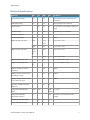
1
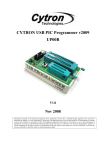
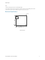
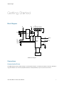
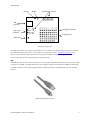
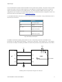
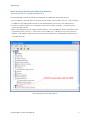
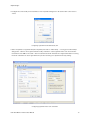
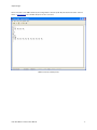
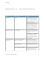
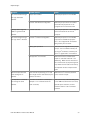
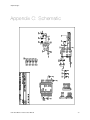
Heart Rate Monitor Interface
User Manual
danjuliodesigns
Revision 1.0
danjuliodesigns
Table of Contents
Heart Rate Monitor Interface
Description
Features
Applications
Version Information
Disclaimer
Contact
Electrical Specifications
Mechanical Specifications
Getting Started
Block Diagram
Connections
Communication/Power
Configuration Jumpers
Status Indicators Prototype Connections Orientation with Polar Transmitter
Quick Test
Quick Test with Host Computer
Quick Test using HyperTerminal (Microsoft Windows)
Quick Test using QuickTerm (Apple Mac OS X)
Operation
Host Interface Operation
Serial Interface (USB or Logic-level physical interface)
I2C Interface
Heart Rate Monitor Algorithms
Command List
Read Analog Input
Set Utility Port Directions
Get Heart Rate Data
Heart Rate Monitor Interface User Manual
3
3
3
3
4
4
4
5
6
7
7
7
7
10
11
11
12
13
13
14
18
20
20
20
21
22
23
24
25
26
1
danjuliodesigns
Get Utility Port
Get Mode
Set Utility Port
Set Mode
Get Version
Appendix A: Troubleshooting
Appendix B: Code Examples
Unix/Mac OS X using the serial interface
Processing using the serial interface
Arduino using I2C
Appendix C: Schematic
Heart Rate Monitor Interface User Manual
27
28
29
30
31
32
34
34
38
40
43
2
danjuliodesigns
Heart Rate Monitor Interface
Description
The Heart Rate Monitor Interface (HRMI) is an intelligent peripheral device that converts the ECG signal from Polar Electro
Heart Rate Monitor (HRM) transmitters into easy-to-use heart rate data. It implements a sophisticated algorithm for
computing an average heart rate even with noisy or intermittent data from the transmitter. The HRMI also provides
analog inputs and a digital input/output utility port to ease integration into custom applications.
Features
• Multiple interfaces: USB, Logic-level serial and I2CTM
• Dual heart rate processing algorithms: averaged and raw
• Uses the RMCM01 Polar OEM receiver
• Compatible with coded and non-coded Polar transmitters including T31, T31C, T61C and Wearlink®
• 32-entry heart rate data history buffer
• Four 8-bit ADC inputs
• Up to a 5 channel digital input/output utility port
• Simple command/response interface
• Programmable power-on default operation
Applications
• Custom exercise equipment
• Portable heart rate monitoring devices
• Bio-feedback devices
• Heart beat aware body-worn electronics
Heart Rate Monitor Interface User Manual
3
danjuliodesigns
Version Information
Datasheet
HRMI
Revision
Firmware
Comments
Version
1.0
0x01
Initial Release
Disclaimer
Copyright © danjuliodesigns, LLC, 2008, All rights reserved.
Neither the whole nor any part of the information contained in, or the product described in this manual, may be adapted
or reproduced in any material or electronic form without the prior written consent of the copyright holder.
This product and its documentation are supplied on an as-is basis and no warranty as to their suitability for any particular
purpose is either made or implied.
danjuliodesigns, LLC. will not accept any claim for damages howsoever arising as a result of use or failure of this product.
Your statutory rights are not affected.
This product is not a medical grade ECG or EKG monitor. This product or any variant of it is not intended for
use in any medical appliance, device or system in which the failure of the product might reasonably be
expected to result in personal injury.
This document and the functionality of the product may be subject to change without notice.
Contact
Email: [email protected]
Website: http://www.danjuliodesigns.com/sparkfun/hrmi.html
Heart Rate Monitor Interface User Manual
4
danjuliodesigns
Electrical Specifications
Parameter
Min
External Voltage Supply
3.6
Typ
Max
Unit
Conditions
5.5
V
When powered from the external power
connection
USB Voltage Supply
4.5
External Current
5
5.5
V
When powered from a USB host
30
45
mA
No connection to any Analog or Utility port
signal
Reception Range
80
Reception Frequency
92
100
5.5
cm
Typical using a T31 transmitter
kHz
Analog Voltage Range
VSS
VCC
V
Note 1
Utility Port Input Low Level
VSS
0.15*
V
3.3V ≤ VCC ≤ 4.5V
VCC
Utility Port Input High Level
VSS
0.8
V
4.5V ≤ VCC ≤ 5.5V
0.25*
VCC
V
3.3V ≤ VCC ≤ 4.5V
VCC
V
4.5V ≤ VCC ≤ 5.5V
0.6
V
IOL = 8.5 mA, VCC = 4.5V
V
IOH = -3.0 mA, VCC = 4.5V
10k
Ω
Note 2
25
mA
Note 3
25
mA
Note 3
55
pF
VCC +
0.8
2
Utility Port Output Low Level
Utility Port Output High Level
VCC 0.7
Maximum Analog Port Source
Impedance
Maximum output current sunk by
any Utility Port signal
Maximum output current sourced
by any Utility Port signal
Capacitive Loading Analog and
Utility ports
Configuration EEPROM write
100K
1M
Write
cycles
Configuration EEPROM
TA ≤ 85ºC
Cycles
40
Year
characteristic retention
Provided no other specifications are
violated
Operating Temperature Range
0
20
60
ºC
Storage Temperature Range
-30
20
70
ºC
Heart Rate Monitor Interface User Manual
5
danjuliodesigns
Notes
1. VSS is on-board ground, VCC is on-board voltage supply.
2. The maximum Analog Port Source impedance is required in order for the ADC sampling time to be met.
3. Total current sourced or sunk by all Utility Port signals must be less than 80 mA.
Mechanical Specifications
4 x 100
USB
1850
100
2000
100
All Dimensions in mil
Board Dimensions
Heart Rate Monitor Interface User Manual
6
danjuliodesigns
Getting Started
Block Diagram
3.3V
OP7
OP6
OP5
OP4
OP3
OP2
OP1
OP0
5V
TX
USB
FT232RL
TX
RX
5V
RX-I
TX-O
GND
8
RX
SJ1
PIC
16F913
4
2
RX/SDA
TX/SCL
AIN3:0
P1:0
Status
HR
RST
RMCM-01
HRMI Block Diagram
Connections
Communication/Power
The HRMI receives power and data through a communication interface. It provides two interface connectors: USB and a
Logic-level header. Use of the two physical interfaces is mutually exclusive, only one can be in use at a time.
Heart Rate Monitor Interface User Manual
7
danjuliodesigns
TX LED
Configuration Jumpers
OP7
OP6
OP5
OP4
OP3
OP2
OP1
OP0
RX LED
Logic-Level
connector
GND
5V
3.3V
P1
P0
AN3
AN2
AN0
SJ1
5V
GND
RX-I / SDA
TX-O / SCL
AN1
USB
connector
Prototype Connections
Prototype Area
Status LED
Board Layout (Top View)
The HRMI communicates using either a serial interface or an I2C interface. The HRMI is configured at power-on reset to
use a particular interface with the OP0 - OP7 jumper block as described in section “Configuration Jumpers” of this
chapter. It communicates using a serial interface through either the USB connector or the Logic-level header. It
communicates using the I2C interface through the Logic-level header.
USB
A USB Mini-B connector allows quick connection to a host computer. The USB interface provides both power and a data
connection to the HRMI. The USB interface uses a FTDI FT232RL interface IC that exposes the HRMI as a serial device
to the host computer. FTDI provides royalty free drivers for Microsoft Windows, Apple Macintosh and Linux operating
systems.
USB Cable with Mini-B connector
Heart Rate Monitor Interface User Manual
8
danjuliodesigns
To use the USB interface a jumper should be installed in the SJ1 position (factory default). The jumper in the SJ1 position
connects the TX line on the FTDI FT232RL interface IC to the HRMI micro-controller RX input (the micro-controller TX
output is permanently connected to the FT232RL RX input). No jumper should be installed in the OP0 position. This
configures the micro-controller to use a serial interface at power-on. The desired baud rate is configured on the OP1 and
OP2 jumper positions as described in section “Configuration Jumpers”.
A 4-pin header allows direct connection for access to Logic-level serial or I2C interfaces. It also provides Ground and +5
volt power input connections.
Label
Function
5V
+5 volt power input
GND
Ground
RX-I / SDA
HRMI Serial TTL RX input
HRMI I2C SDA (data)
TX-O / SCL
HRMI Serial TTL TX output
HRMI I2C SCL (clock)
Logic-level header pin description
The HRMI is a serial device operating at baud rates from 2400 - 38400 when jumper OP0 is uninstalled. Data is
transmitted at TTL signal levels using 8 data bits, 1 stop bit and no parity (8N1). Jumper positions OP1 - OP2 configure
the baud rate. An example of interfacing the HRMI to an external microprocessor using a serial interface is shown below.
Baud
TX
RX-I
uP
RX
TX-O
VSS
GND
SJ1
OP0
+5
OP2
VDD
OP1
VCC
HRMI
Uninstalled
Interfacing with a microprocessor through a TTL serial port
Heart Rate Monitor Interface User Manual
9
danjuliodesigns
The HRMI is a 7-bit I2C slave operating at up to a 100 kHz data rate when jumper OP0 is installed. Jumper positions
OP1 - OP7 configure the I2C address (OP1 is LSb). The HRMI does not provide pull-up resistors on the I2C signals. It
may be necessary to add these externally. An example of interfacing the HRMI to an I2C device is shown below. More
than one I2C device can be wired in parallel observing signal line capacitance limits. Each device must respond to a
different address. For more information about I2C please see http://www.standardics.nxp.com/support/documents/i2c.
VCC
Installed
2 x 4.7 k
uP
SCL
TX-O / SCL
VSS
GND
SJ1
OP0
OP1
OP2
OP3
RX-I / SDA
OP4
SDA
OP5
+5
OP7
VDD
OP6
Address
HRMI
Uninstalled
Interfacing with an I2C master
Jumper SJ1 should be removed when using the Logic-level 4-pin header (to disconnect the output port on the
FT232RL).
Configuration Jumpers
Configuration jumpers are used to configure the HRMI for operation. The jumpers are two exposed pads situated close
together. To install a jumper use a soldering iron to dab a small amount of solder that covers both pads. To remove a
jumper heat and remove the liquid solder by dragging the soldering iron tip quickly sideways across the pads to allow the
surface tension of the solder to separate it into two blobs, one on each pad. Alternatively use the soldering iron to melt
the solder and remove it using a small piece of solder-wick. Be careful not to apply to much heat or the solder pads may
pull up off of the board .
Configuration jumper SJ1 is used to connect the TX line on the FTDI FT232RL interface IC to the HRMI micro-controller
RX input when using the USB interface.
Configuration jumpers OP0 - OP7 configure the micro-controller communication interface at power-up. They are only
read at power-up. OP0 configures the interface type. Without a jumper across OP0 the micro-controller communicates
using a serial interface through either the Logic-level connector or USB connector. With a jumper across OP0 the microcontroller communicates using the I2C protocol.
Heart Rate Monitor Interface User Manual
10
danjuliodesigns
With OP0 removed, OP1 and OP2 configure the baud rate. OP3 - OP7 are unused. The data protocol is 8 data bits, 1
stop bit and no parity (8N1). By default, with no jumpers installed, the baud rate is 9600 baud.
OP2
OP1
Baud Rate
installed
installed
2400 baud
installed
uninstalled
19200 baud
uninstalled
installed
38400 baud
uninstalled
uninstalled
9600 baud
Serial Interface (OP0 uninstalled)
Note: The baud rate configured with jumpers OP1 and OP2 must match the baud rate selected by the
software running on the host computer.
With OP0 installed, OP1 - OP7 configure the 7-bit I2C slave address. OP1 is the least-significant bit. The maximum I2C
transfer rate is 100 kHz. By default with no jumpers (other than OP0) installed, the address is 127.
OP7
OP6
OP5
OP4
OP3
OP2
OP1
Address
installed
installed
installed
installed
installed
installed
installed
0
installed
installed
installed
installed
installed
installed
uninstalled
1
installed
installed
installed
installed
installed
uninstalled
installed
2
installed
installed
installed
installed
installed
uninstalled
uninstalled
3
...
uninstalled
...
uninstalled
uninstalled
uninstalled
uninstalled
uninstalled
uninstalled
127
I2C Interface (OP0 installed)
Status Indicators
The HRMI contains three status LEDs.
1. USB TX: Red LED that flashes for data transmitted from the host to the HRMI through the USB interface.
2. USB RX: Green LED that flashes for data transmitted from the HRMI to the host through the USB interface.
3. Status: Green LED that indicates the status of the HRMI. It is on when the HRMI is searching for valid heart beat data.
It blinks at the detected heart rate when a signal is acquired. For each heart beat it is on for 100 mSec.
Prototype Connections
The HRMI provides four analog inputs and two programmable digital input/outputs along with a small prototyping area to
include local circuitry. The analog inputs are connected to the HRMI micro-controller 8-bit ADC inputs. The
programmable digital input/output ports are connected to general purpose I/O pins on the HRMI micro-controller and
Heart Rate Monitor Interface User Manual
11
danjuliodesigns
can be configured to be either a digital input or digital output and drive logic-level signals. Both +5 volts and +3.3 volts
are available.
Label
Function
AN0 - AN3
Analog Input
P0 - P1
Programmable digital I/O (Utility port)
3.3V
+3.3 volt supply rail. Power draw from this pin should
be limited to a maximum of 50 mA.
5V
+5 volt supply rail. Connected to the 5V input
connector and to the USB power rail. Care must be
taken not to exceed USB current limits.
GND
Board Ground
Prototype Signals
Orientation with Polar Transmitter
Polar transmitters use a magnetic field to transmit data to the RMCM-01 OEM receiver on the HRMI board. The
following rules help maximize signal transfer between a polar transmitter and the HRMI.
1. The maximum distance between the transmitter and HRMI should not exceed 80 cm.
2. The magnetic field is generated and detected using coils in the transmitter and receiver. The receiver coil should be in
parallel with the magnetic flow generated by the transmitter for maximum energy transfer as illustrated in the following
diagram.
Transmitter
Strap
RMCM01
USB
HRMI
Transmitter and receiver orientation
3. Metal casing around the receiver may form a Faraday cage around the receiver attenuating the signal. A metal cage
may also change the orientation of the magnetic field coming from the transmitter.
Heart Rate Monitor Interface User Manual
12
danjuliodesigns
4. Interference created by other electronic devices (such as motors, displays and power supplies) may interfere with the
transmission of information from the transmitter to receiver. Optimally the HRMI will be physically separated from such
sources of electro-magnetic energy.
Quick Test
The ability of the HRMI to detect a heart rate can be tested with just a Polar transmitter and 5 volt regulated power
supply.
Attach the HRMI to the 5 volt power supply and switch on the power supply. Alternatively plug the HRMI board into a
computer USB port. The HRMI Status LED should light.
Strap on the Polar transmitter and orient yourself near the HRMI board. Within 15 seconds the HRMI Status LED should
begin to flash indicating it has detected heart rate data from the transmitter. The Polar transmitter operation can be
verified with a Polar wristwatch receiver.
Quick Test with Host Computer
A computer with USB interface and terminal emulator program can access the HRMI. A USB cable and Polar transmitter
are required in addition to the computer. The basic steps are listed below. Some specific instructions for particular
platforms follow in subsequent sections.
1. Install a jumper at position SJ1. Make sure there are no jumpers installed on positions OP0 - OP7.
2. Before attaching the HRMI to the computer download and install the appropriate driver from the FTDI website: http://
www.ftdichip.com/FTDrivers.htm. The website contains the most current driver and instructions for each supported
operating system. Be sure to load the Virtual COM Port Driver (VCP) for this test instead of the D2XX driver. The VCP
driver makes the HRMI appear as a standard serial device (COM port).
3. Once the driver has been installed then attach the HRMI to the computer’s USB interface. The HRMI Status indicator
should light and blink when a heart beat is detected from a Polar transmitter.
4. Start a serial terminal emulator program on the host computer (for example, Hyperterminal on Microsoft Windows).
Make sure it is configured to use the USB-based communication port associated with the HRMI at 9600 baud, 8 bit
data, 1 stop bit and no parity. It is handy but not necessary to configure the terminal emulator program to echo back
characters typed locally and to append a linefeed character to received line ends. This allows display of the command
sent to the HRMI as well as the result returned by the HRMI.
5. Type the following command at the terminal emulator: “G1 <CR>”. That is the three characters “G” followed by “1”
followed by the carriage return (“Enter” key or control character for carriage return, CTRL-M). This should result in a
string such as the following.
1 15 63
where the first number, “1”, indicates the current heart rate algorithm mode, the second number, “15”, indicates the
current timer value and the third number, “63”, the current heart rate (your actual heart rate may vary). See the section
“Command List” for a detailed description of this and other commands.
Heart Rate Monitor Interface User Manual
13
danjuliodesigns
Quick Test using HyperTerminal (Microsoft Windows)
These examples are shown using Microsoft Windows XP™.
Use Device Manager to identify the COM port associated with the HRMI before starting HyperTerminal.
1. Plug the HRMI into a USB port (after the FTDI driver has been loaded). Verify the Status LED is lit. It may be helpful if
the HRMI is the only USB peripheral attached as other USB peripherals may also use a FTDI USB Interface IC.
2. Left-click on the My Computer icon on the desktop or Start menu and select “Properties”. This will bring up the
“System Properties” window.
3. Select “Device Manager” from the “System Properties” Window. The “Device Manager” window will appear as shown
in the following picture. Click the “+” symbol next to “Ports (COM & LPT)” to display a list of ports the system has
identified. A new COM port will be listed as shown (assuming the HRMI is the only USB peripheral attached using a
FTDI USB Interface IC).
Device Manager showing a USB COM port
Heart Rate Monitor Interface User Manual
14
danjuliodesigns
Start and configure HyperTerminal (HyperTerminal is located in “All Programs -> Accessories -> Communications”).
Configuration consists of the following illustrated steps.
1. Create a new connection configuration, for example “com7_9600”, in the “Connection Description” dialogue box.
HyperTerminal can save this configuration to disk for use at a later time.
Configuring HyperTerminal with a new configuration
2. Select the COM port associated with the HRMI in the “Connect To” dialogue box.
Configuring HyperTerminal to use the USB COM port
Heart Rate Monitor Interface User Manual
15
danjuliodesigns
3. Configure the correct serial port characteristics in the “Properties” dialogue box. Be sure that flow control is set to
“None”.
Configuring HyperTerminal for 9600 baud, 8N1
4. Select “Properties” for HyperTerminal (File->Properties) then click on “ASCII Setup…” to bring up the “ASCII Setup”
dialogue box. Click the “Echo typed characters locally” checkbox to cause HyperTerminal to echo the characters
transmitted to the HRMI on the screen. Click the “Send line ends with line feeds” and “Append line feeds to incoming
line ends” checkboxes to cause HyperTerminal to put each text string on a separate line for easy viewing.
Configuring HyperTerminal to echo characters
Heart Rate Monitor Interface User Manual
16
danjuliodesigns
Send commands to the HRMI followed by the Carriage Return character (CTRL-M) and observe the results. See the
section “Command List” for a detailed description of each command.
HRMI Commands and Responses
Heart Rate Monitor Interface User Manual
17
danjuliodesigns
Quick Test using QuickTerm (Apple Mac OS X)
QuickTerm is a simple universal terminal application compatible with Mac OS X 10.2 - 10.5. It can be found at the
developer’s website http://www.gelhaus.net/cgi-bin/showpage.py?cocoa/+quickterm.html or through the version tracker
website (http://www.versiontracker.com).
Currently QuickTerm (version 1.01) is limited to a maximum of 19200 baud. The HRMI must be configured to work at
19200 baud or less. This example uses the default baud rate of 9600 baud.
1. Plug the HRMI into a USB port (after the FTDI driver has been loaded). Verify the Status LED is lit. It may be helpful if
the HRMI is the only USB peripheral attached as other USB peripherals may also use a FTDI USB Interface IC.
2. Start QuickTerm and configure the serial port by clicking on the “Port settings…”. Select the appropriate device from
the “Port” pull-down menu. The entry will have the form “/dev/cu.usbserial-XXXXXXXX” where the string “XXXXXXXX”
is unique to each FTDI FT232RL IC. Select 9600 baud. Make sure there is no flow control enabled and select the
“Local echo” checkbox.
Example QuickTerm Port Settings
Heart Rate Monitor Interface User Manual
18
danjuliodesigns
3. Click the “Connect” button and send commands to the HRMI followed by the Carriage Return character (CTRL-M) and
observe the results. See the section “Command List” for a detailed description of each command.
HRMI Commands and Responses
Note: Do not disconnect the HRMI from the Macintosh USB port while any application is using the serial port
(the serial port is open). This may cause the system to freeze or crash.
Heart Rate Monitor Interface User Manual
19
danjuliodesigns
Operation
Host Interface Operation
The HRMI is a slave device. It responds to commands issued to it from a host controller. It interprets commands from
either a serial or I2C interface. Both interfaces use the same physical I/O ports on the HRMI micro-controller. The
interface type is selected by sampling jumper OP0 at power-on. The interface type persists until the next power-on reset.
The HRMI is capable of receiving commands 250 mSec after being powered up.
Unknown or illegal commands are ignored. Some commands cause the HRMI to generate a response which it transmits
back to the host controller after processing the command.
Commands are 1-byte (8-bits in length). They have ASCII representations that are an abbreviation of their function.
Some commands are followed by an argument representing a single 8-bit numeric quantity.
Responses consist of one or more numeric values.
Commands and responses are encoded slightly differently for serial and I2C communication.
Serial Interface (USB or Logic-level physical interface)
Commands and arguments sent through the serial interface are encoded as ASCII values. Commands are a single ASCII
character with values between ‘A’ and ‘Z’. Arguments are one to three ASCII numbers “0” through “255” representing an
8-bit value. Commands are issued in Command Sequences. A Command Sequence consists of the command value
followed by any required argument terminated with the Carriage Return character (0x0D). Space characters may be
included between the command and argument or between the argument and the Carriage Return (<CR>). Any other
characters or additional arguments cause the HRMI to ignore the Command Sequence up to the next Carriage Return.
Responses consist of ASCII numbers (“0” through “255”) separated by spaces terminated with the Carriage Return
character.
Heart Rate Monitor Interface User Manual
20
danjuliodesigns
For example the ASCII character ‘G’ is used for the Get Heart Rate command. It is always followed by an argument with
a value of 0 - 32 commanding the HRMI to return 0 - 32 heart rate values from its heart rate history buffer. The HRMI
also includes two status bytes prior to the requested heart rate data.
Sending the command
G3<CR>
or
G 3 <CR>
generates a response with the form
1 25 63 64 67 <CR>
where the values “1” and “25” are the status bytes (explained later in this chapter) and the values “63”, “64” and “67” are
the requested heart rate values (in beats-per-minute) from the heart rate history buffer.
The HRMI can buffer multiple serial commands and arguments in an internal 16-byte FIFO. It processes one command
at a time (including transmission of a required response). The HRMI will continue to push new commands into the FIFO
while it is processing a command. It will drop commands when the FIFO is full. Care must be taken when sending
commands immediately following a Get Heart Rate command and before receiving the response from the Get Heart Rate
command so as not to overflow the FIFO.
I2C Interface
The HRMI implements a simple 7-bit slave I2C device. It is configured with any 7-bit I2C address on the OP1-7
configuration jumpers at power-on. The HRMI implements only the mandatory I2C slave functionality described in the
NXP Semiconductor document “UM10204 I2C-bus specification and user manual”. These functions include START
condition, STOP condition, Acknowledge and 7-bit slave address. It does not support General Call address, 10-bit slave
address, Software reset or Device ID. The maximum bit rate is 100 kHz.
Commands and arguments are encoded as 8-bit binary values. Command Sequences consist of 1- or 2-byte I2C write
sequences (the command byte followed by any required argument byte) followed by the STOP condition.
The host controller must issue a read of the expected number of data bytes for commands that generate a response.
The read should be issued following the write and before subsequent commands. The HRMI stretches the clock on the
SCL line during the read while it fetches data bytes internally to satisfy the read. The HRMI will return the value 0x00 for
host controller I2C reads that request more data than the is contained in the response or for reads without a prior
command.
The example shown in the Serial Interface section above would consist of the following bytes transmitted on the I2C
interface for the command.
<0x47><0x03>
The following response data would be read (the host controller must read 5 bytes for this example).
<0x01><0x19><0x3F><0x40><0x43>
The HRMI can buffer multiple I2C commands and arguments in an internal 16-byte FIFO. However it can only process
one command at a time that requires a response. This is because it resets the internal buffer it uses to hold responses
Heart Rate Monitor Interface User Manual
21
danjuliodesigns
each time a command is received from the I2C interface. The host controller must execute a read and obtain the
response data for any command that generates a response before issuing another command.
Heart Rate Monitor Algorithms
The HRMI computes the heart rate by measuring the time from one heart beat to the next as received from the Polar
transmitter. The transmitter sends a pulse for each heart beat it detects. During normal operation the data from the Polar
transmitter may contain a significant amount of spurious information. For example a slightly loose transmitter strap may
generate extra pulse information each time the strap contacts are jostled (as can occur frequently when running). Other
devices can also generate electromagnetic pulses that appear to the receiver as heart rate data.
The HRMI allows access to the received data in either raw or averaged form (Raw or Average mode). In Raw mode the
instantaneous heart rate based on each pulse is calculated and stored in a 32-entry history buffer. Raw mode data is
useful for observing dynamic heart response on a beat-by-beat basis although the data may include erroneous heart rate
values due to spurious pulses. It is the responsibility of software running on the host controller or user analysis to identify
possibly spurious heart rate values in raw data.
In Average mode the instantaneous heart rate data is averaged and the average heart rate, computed once per second,
is pushed into the 32-entry history buffer. The averaging algorithm identifies and ignores spurious heart rate data when
generating the average by using a pulse rate discriminator and a dual set of averaging buffers (a primary buffer and an
acquisition buffer). The acquisition buffer is used to determine the initial average. Once an average has been computed
the primary buffer is used to maintain calculations of the average. The primary buffer is dynamically sized from 6 to 16
entries using more entries for higher average heart rates to prevent slightly spurious values from affecting the average too
much while allowing the average to be responsive to quickly changing heart rates. Once an average has been computed
the acquisition buffer is used when spurious values too large for the primary averaging buffer are detected. The
acquisition buffer requires a certain number of values within a range before determining that there is a new average. The
discriminator is used to detect spurious values for both the primary and acquisition buffer.
The algorithm is selected from a built-in EEPROM at power-up. The algorithm may also be changed while the HRMI is
running by issuing a command. From the factory the power-up value configures the HRMI to use the Averaged
algorithm. The power-up value may also be changed by issuing a command to the HRMI.
In raw mode the current instantaneous heart rate value is pushed into the heart rate history buffer each time a pulse is
received. In average mode the current average is pushed into the heart rate history buffer each second while nonspurious data is being received. The history buffer is not loaded in average mode while spurious data is being received.
The last entry pushed into the history buffer represents the most recent accurate average heart rate. The HRMI clears
the heart rate history buffer when there has been a loss-of-signal from the transmitter for more than fifteen seconds. It
also clears the heart rate history buffer if more than 64 spurious pulse values are received. When the heart rate history
buffer has been cleared or before any values have been loaded the HRMI will generate responses with the value of 0 for
the heart rate.
The status indicator LED is pulsed on for 100 mSec when a pulse is received. It is set to a solid on condition when no
pulse has been received in more than 1792 mSec setting a lower bound to detectable heart rate values at 34 beats-perminute (bpm). The upper bound to detectable heart rate values is 239 bpm.
Heart Rate Monitor Interface User Manual
22
danjuliodesigns
Command List
The HRMI implements the following commands, summarized in the following table and described more fully in the
following sections.
Command
Read Analog
ASCII
Hex
Command
Command
Command
Argument
Value
Value
A
0x41
Channel 0-3
Response
Description
8-bit value
Trigger the ADC to read the
Input
Set Utility Port
specified analog input.
D
0x44
Directions
Get Heart Rate
5-bit direction
-
mask
G
0x47
Data
Set the direction, either input or
output, of each Utility port pin.
Number of
2 - 34 8-bit
Get the specified number of heart
heart rate
values
rate values and status information
history buffer
from the heart rate history buffer.
entries 0-32
Get Utility Port
I
0x49
-
5-bit value
Get the current value of each
Utility port pin.
Get Mode
M
0x4D
-
1 1-bit value
Get the current heart rate
followed by 1 5-
algorithm and Utility port direction.
bit value
Set Utility Port
O
0x4F
5-bit value
-
Set the value of each Utility port
pin.
Set Mode
S
0x53
3-bit mode
-
Set the heart rate algorithm and
optionally set the power-on
defaults for heart rate algorithm
and Utility port direction and value.
Get Version
V
0x56
-
2 8-bit values
Get information about the
firmware running in the HRMI.
HRMI Command List
Heart Rate Monitor Interface User Manual
23
danjuliodesigns
Read Analog Input
Description
Trigger the HRMI to read the analog voltage level on one of the analog inputs and return the value as an 8-bit number.
Serial command
A<N><CR>
I2C command
<0x41><N>
Argument
<N> specifies the analog input to read, 0-3. Other values cause the command to be ignored.
Serial response
Returns 1 8-bit byte with the ADC value encoded as an ASCII string “0 ” to “255 ” followed by <CR>.
I2C response
Read 1 8-bit byte with the ADC value.
Notes
1. The HRMI delays 5 uSec after configuring the specified analog input before triggering the ADC to allow the sampling
capacitor in the ADC time to charge. The maximum input impedance seen by any analog input pin should be less
than 10 kΩ to allow the capacitor to fully charge in this time.
2. The internal micro-controller ADC is referenced to the 5 volt power rail which means the analog inputs are scaled
relative to the power rail. It is possible to use a precision reference voltage by attaching the voltage reference to one of
the analog inputs. Voltage levels attached to other analog inputs can be scaled by the voltage reference by dividing
the result read from the desired analog input by the result read from the reference analog input.
Heart Rate Monitor Interface User Manual
24
danjuliodesigns
Set Utility Port Directions
Description
Set the I/O direction of each Utility port digital pin. Pins can either be an input or an output.
Serial command
D<N><CR>
I2C command
<0x44><N>
Argument
<N> is a 5-bit mask (bits 4:0) specifying the direction of each Utility port pin. A value of 0 in a bit position makes that bit
an output, a value of 1 in a bit position makes that bit an input. Data in bit positions 7:5 is ignored. Legal values for the
argument are from 0 to 31.
Serial response
n/a
I2C response
n/a
Notes
1. The HRMI firmware and micro-controller support 5 utility port pins, P0-P4. This implementation makes P0 and P1
available at the prototype area. P2 - P4 are available at the I/O pins of the micro-controller (pins 13-15). There are no
additional PCB pad area so extreme care must be taken if attaching a wire or other device lead to these pins.
Note: Damage to the HRMI caused by soldering to the additional utility port pins is not covered under
warranty.
2. The Utility port pin power-on default direction is set at the factory to be all outputs with an output value of 0.
3. Switching a Utility port pin from input to output will cause it to reflect the most recent value sampled as an input.
Heart Rate Monitor Interface User Manual
25
danjuliodesigns
Get Heart Rate Data
Description
Request 0 - 32 heart rate samples from the heart rate history buffer.
Serial command
G<N><CR>
I2C command
<0x47><N>
Argument
<N> specifies the number of heart rate samples to return. The value is limited by the HRMI to a maximum of 32.
Serial response
Returns <STATUS> <COUNT> <HR1> <HR2> … <HRN> encoded as ASCII strings “0 ” to “255 ” followed by <CR>.
I2C response
Read 2+N 8-bit bytes: <STATUS><COUNT><HR1><HR2>...<HRN>
Notes
<STATUS> byte
7:4: Reserved. Will read as 0
3: Bad Data. When set to 1 indicates that the heart rate history buffer was cleared because more than 64 consecutive
spurious heart beat pulses have been received. A spurious heart beat pulse is defined as one that is more than 25%
greater than or less than the current average or the average in the acquisition buffer. Set to 0 when the heart rate
history buffer is collecting heart rate values.
2: Reacquiring Series. Set to 1 when the most current heart beat pulse was more than 25% greater than or less than
the current average and is being included in the acquisition buffer. Set to 0 when the most current heart beat pulse
was added to the current average value.
1: No Data. Set to 1 when no heart beat signal has been detected within the last 1792 mSec. Set to 0 when at least
two consecutive heart beats have been detected.
0: Algorithm mode. Set to 1 for average mode, set to 0 for raw mode.
<COUNT> byte indicates the current second in average mode and the current sample count in raw mode modulo 256 of
the last heart rate value entered into the heart rate history buffer (<HR1>). It is designed to be used when multiple values
are read periodically. It allows software on the host system to identify the start of new data in each group of values read
from the HRMI.
<HR1> is the most recent heart rate value in the heart rate history buffer.
<HR2> is the second most recent heart rate value in the heart rate history buffer and so on.
Heart Rate Monitor Interface User Manual
26
danjuliodesigns
Get Utility Port
Description
Read the current value of the Utility port.
Serial command
I<CR>
I2C command
<0x49>
Argument
n/a
Serial response
Returns 1 5-bit number with the Utility port value encoded as an ASCII string “0 ” to “31 ” followed by <CR>.
I2C response
Read 1 8-bit byte with the Utility port value in bits 4:0. Bits 7:5 are 0.
Notes
1. The value returned is the value for each Utility port bit regardless of its direction. Utility port pins that are configured as
inputs return the value on the input. Utility port pins that are configured as outputs return the value that is being driven.
Heart Rate Monitor Interface User Manual
27
danjuliodesigns
Get Mode
Description
Request the current heart rate algorithm and Utility port direction.
Serial command
M<CR>
I2C command
<0x4D>
Argument
n/a
Serial response
Returns <ALG> with the heart rate algorithm encoded as an ASCII string “0 ” to “1 ” followed by <DIR> with the current
Utility port direction encoded as an ASCII string “0 “ to “31 “ followed by <CR>.
I2C response
Read 2 8-bit bytes: <ALG><DIR>.
Notes
<ALG> byte
7:1: Reserved. Set to 0.
0: Algorithm. 1 = Averaged, 0 = Raw mode.
<DIR> byte
7:5: Reserved. Set to 0.
4:0: Utility Port Direction: A 1 in a bit position signifies that bit is an input, a 0 in a bit position signifies that bit is an
output.
Heart Rate Monitor Interface User Manual
28
danjuliodesigns
Set Utility Port
Description
Set the value of Utility port output pins.
Serial command
O<N><CR>
I2C command
<0x4F><N>
Argument
<N> is a 5-bit mask (bits 4:0) specifying the value for each Utility port output pin. Legal values for the argument are from
0 to 31.
Serial response
n/a
I2C response
n/a
Notes
1. Utility port pins defined as inputs are unaffected by data from this command.
2. The Utility port pin power-on default output value is set at the factory to all 0s.
Heart Rate Monitor Interface User Manual
29
danjuliodesigns
Set Mode
Description
Set the heart rate algorithm mode and optionally store it and/or the current Utility port direction and output values to
internal EEPROM to be used at the next power-up reset.
Serial command
S<N><CR>
I2C command
<0x53><N>
Argument
<N> is a 3-bit mask (bits 2:0) specifying the algorithm mode and if it and/or the current Utility port direction and output
values should be stored to EEPROM. Data in bit positions 7:3 is ignored. Legal values for the argument are from 0 to 7.
2: Set to 1 to trigger the HRMI to store the current Utility port direction and output values to EEPROM
1: Set to 1 to trigger the HRMI to store the heart rate algorithm (specified by bit 0) to EEPROM.
0: Algorithm. Set to 1 for average mode, set to 0 for raw mode.
Serial response
n/a
I2C response
n/a
Notes
1. This command is used to configure the power-on state of the HRMI.
2. It takes a maximum of 6 mSec for the HRMI to store each value (Utility port direction, Utility port output values and/or
heart rate algorithm) to internal EEPROM. During this time the HRMI does not process other commands although it
continues heart rate data processing.
Heart Rate Monitor Interface User Manual
30
danjuliodesigns
Get Version
Description
Request information about the firmware running in the HRMI.
Serial command
V<CR>
I2C command
<0x56>
Argument
n/a
Serial response
Returns <TYPE> <VERSION> encoded as ASCII strings “0 ” to “255 ” followed by <CR>.
I2C response
Read 2 8-bit bytes: <TYPE><VERSION>.
Notes
<TYPE> byte specifies the firmware type. For the HRMI this byte value is 0x01. Allows software running on a host
controller to identify the device it is communicating with.
<VERSION> byte specifies the current HRMI firmware version. The firmware version is incremented when firmware
changes are made to the HRMI that are externally visible to software running on the host controller.
Heart Rate Monitor Interface User Manual
31
danjuliodesigns
Appendix A: Troubleshooting
Symptom
Possible Causes
Action
No status LED
No Power
Power through USB: Make sure that the
USB port is enabled to supply power. A
short or excessive current draw on an
USB port may cause the host computer
to shut down the USB port.
Power through Logic-level connector:
Make sure the input voltage is between
4.5 and 5.5 volts, that the polarity is
correct and that the power supply can
supply enough current for the HRMI and
any additional powered circuitry.
Status LED does not blink
No Heart rate signal
Polar Transmitter battery is dead: Test if
the signal can be received with a Polar
wristwatch.
Poor Positioning: If a Polar wristwatch
receives the signal then attempt to
reposition the transmitter closer and
parallel with the RMCM-01 OEM receiver
on the HRMI PCB.
No communication through
Software on the host computer has
Make sure that the host software is
the USB interface.
opened the wrong serial device.
opening the device associated with the
HRMI. The RX LED should flash when
commands are transmitted to the HRMI.
Jumper SJ1 not installed
Make sure jumper SJ1 is installed.
Incorrect serial interface configuration
Make sure jumper OP0 is not installed
and make sure jumpers OP1-2 are
configured for the correct baud rate.
Heart Rate Monitor Interface User Manual
32
danjuliodesigns
Symptom
Possible Causes
Action
No communication through
Jumper SJ1 installed
Make sure jumper SJ1 is not installed.
Incorrect serial interface configuration
Make sure jumper OP0 is not installed
the Logic-level serial
interface.
and make sure jumpers OP1-2 are
configured for the correct baud rate.
Garbage data through the
Incorrect baud rate
Make sure jumpers OP1-2 are configured
USB or Logic-level serial
for the same baud rate as the host
interface.
computer.
No communication through
the Logic-level
I2C
Incorrect I2C interface configuration
interface.
Make sure jumper SJ1 is not installed,
jumper OP0 is installed and jumpers
OP1-7 are configured with the address
being used by the I2C master.
Missing pull-up resistors
Make sure the I2C signals have the proper
pull-ups. Some controllers include pullups in their I2C interface, otherwise pullup the I2C signals with 4.7 kΩ resistors.
Unsupported I2C commands
Make sure the host controller issues
simple I2C read and writes with 7-bit
addressing. Make sure the writes are for
the command and any required argument
only. Make sure the reads are for exactly
the expected number of response data
bytes.
Receive unexpected 0x00
when reading the
I2C
Host controller is performing an I2C read
Make sure the I2C read only reads the
that is larger than the data returned by the
correct number of bytes.
interface.
previous command.
No response for commands
Extraneous characters in command (for
Make sure the only characters being sent
sent through the serial
example a <LF> character before the
to the HRMI include the ASCII command,
interface.
<CR> character).
optional space characters, numeric
characters and the <CR> termination
character.
Heart Rate Monitor Interface User Manual
33
danjuliodesigns
Appendix B: Code Examples
The basic process for communicating with the HRMI from a host controller consists of the following steps.
1. Open the serial/I2C port
2. Configure the serial/I2C port
3. Send a command
4. Read a response
Unix/Mac OS X using the serial interface
Many PC-based Unix/Linux systems have a built-in serial port that can connect to the HRMI through the Logic-level
interface with an appropriate serial-to-TTL converter chip such as the Maxim MAX3222E or ST Microelectronics ST202E.
Systems with a USB port can communicate directly with the HRMI after downloading and installing a driver from FTDI.
The following C-program illustrates a simple command/response. You will need to change the device string for your
specific serial port device entry.
/*
* Demonstration program for communicating with the HRMI over a serial interface
*/
#include
#include
#include
#include
#include
#include
#include
#include
#include
#include
#include
<stdio.h>
<string.h>
<unistd.h>
<fcntl.h>
<sys/ioctl.h>
<errno.h>
<paths.h>
<termios.h>
<sysexits.h>
<sys/param.h>
<sys/select.h>
// Define a constant specifying the largest response string we could get from the HRMI
#define MAX_RSP_CHARS 140
// Global to hold original serial port attributes
static struct termios gOriginalTTYAttrs;
//
// OpenSerialPort: Routine to open and configure the serial prot
//
Heart Rate Monitor Interface User Manual
34
danjuliodesigns
static int OpenSerialPort(const char *deviceFilePath)
{
// variables
int fd = -1;
// file descriptor for serial port
struct termios options;
// serial port configuration options
// Open the serial port
if ((fd = open(deviceFilePath, O_RDWR | O_NOCTTY )) == -1) {
printf("Error opening serial port %s - %s(%d)\n",
deviceFilePath, strerror(errno), errno);
return(-1);
}
// Prevent other processes from opening the serial port
if (ioctl(fd, TIOCEXCL) == -1) {
printf("Error setting TIOCEXCL on %s - %s(%d)\n",
deviceFilePath, strerror(errno), errno);
return(-1);
}
// Get the serial port current options and save them to restore on exit
if (tcgetattr(fd, &gOriginalTTYAttrs) == -1) {
printf("Error getting tty attributes %s - %s(%d)\n",
deviceFilePath, strerror(errno), errno);
return(-1);
}
// Configure the serial port
options = gOriginalTTYAttrs;
//
Set raw input (non-canonical) mode, with reads blocking until either a
//
single character has been received or a one second timeout expires
cfmakeraw(&options);
options.c_cc[VMIN] = 1;
options.c_cc[VTIME] = 10;
//
Set the baud rate and word length
cfsetspeed(&options, B9600);
options.c_cflag |= (CS8);
//
Cause the new options to take effect immediately
if (tcsetattr(fd, TCSANOW, &options) == -1) {
printf("Error setting tty attributes!\n");
return(-1);
}
return(fd);
}
//
// CloseSerialPort: Close our connection and restore the original settings
//
void CloseSerialPort(int fd)
{
// Block until all written output has been sent from the device
if (tcdrain(fd) == -1) {
printf("Error waiting for drain - %s(%d)\n", strerror(errno), errno);
}
// Reset the serial port back to the state in which we found it
if (tcsetattr(fd, TCSANOW, &gOriginalTTYAttrs) == -1) {
printf("Error restoring tty attributes - %s(%d)\n", strerror(errno), errno);
}
// Close the port
Heart Rate Monitor Interface User Manual
35
danjuliodesigns
close(fd);
}
//
// SendGetHeartRate: Function to send a command to get the number of heart rate values
//
specified in NumEntries
//
//
Returns 1 for success, 0 for failure
//
int SendGetHeartRate(int fd, int NumEntries)
{
char SendCommand[8];
// Array sized to hold the largest command string
int CmdLength;
// Number of characters in the command string
// Validate NumEntries
if (NumEntries < 0)
NumEntries = 0;
else if (NumEntries > 32)
NumEntries = 32;
// Build the command string
//
Note: "\015" is the carriage return character
CmdLength = sprintf(SendCommand, "G%0d\015", NumEntries);
// Send the command string
return(write(fd, SendCommand, CmdLength) == CmdLength);
}
//
// GetResponseString: Function to read a response string back from the HRMI
//
int GetResponseString(int fd, char* ResponseString)
{
char b[2];
int i = 0;
do {
int n = read(fd, b, 1);
if (n == -1)
return(-1);
if (n == 0) {
usleep(10 * 1000);
continue;
}
// read a char at a time
ResponseString[i] = b[0];
i++;
// store the character
// read failed
// wait 10 msec before trying again
// repeat until we see the <CR> character or exceed the buffer
} while ((b[0] != 0x0D) && (i < MAX_RSP_CHARS));
ResponseString[i-1] = 0;
<CR>)
return(0);
}
// null terminate the string (replace the
int main()
{
int sfd;
// serial port file descriptor
int i = 0;
// loop counter
char RspBytes[MAX_RSP_CHARS]; // Response string
Heart Rate Monitor Interface User Manual
36
danjuliodesigns
int numBytes;
// Open the serial port device associated with the HRMI
if ((sfd = OpenSerialPort("/dev/cu.usbserial-A9003PDh")) == -1) {
return(-1);
}
// Send a series of Get Heart Rate commands, each time requesting more history buffer
// entries
while (i++ < 33) {
if (SendGetHeartRate(sfd, i) == 0) {
printf("Error: SendGetHeartRate failed!\n");
break;
}
if (GetResponseString(sfd, RspBytes) == -1) {
printf("Error: GetResponseString failed!\n");
break;
} else {
printf("Request %2d => %s\n", i, RspBytes);
}
sleep(1);
}
CloseSerialPort(sfd);
}
Heart Rate Monitor Interface User Manual
37
danjuliodesigns
Processing using the serial interface
The Processing language and environment includes a Serial library that makes it easy to interface Processing programs
with the HRMI.
The following Processing program illustrates a simple command/response. This program differs from the Unix program
in that we process a received buffer full of ASCII characters manually after we receive it from the HRMI.
//
// Demonstration program for communicating with the HRMI over a serial interface
//
// Include the serial library
import processing.serial.*;
// Variable declaration
Serial port;
byte[] rspCharArray = new byte[32];
int[] rspArgArray = new int[3];
int validData = 0;
int CR = 13;
// The serial port
// Where we'll put the raw data read from the HRMI
// Where we'll put the converted response values
// <CR> constant
void setup() {
// Open a specific serial device (this will change for each HRMI device)
port = new Serial(this, "/dev/tty.usbserial-A9003PDh", 9600);
// Setup the serialEvent to be called when we receive complete response
// packets from the HRMI device
port.bufferUntil(CR);
}
void draw() {
// Send a command to get a single heart rate value
validData = 0;
port.write('G');
port.write('1');
port.write(CR);
// Wait for a response from the HRMI device
while (validData == 0) {
delay(1000);
// Delay 1 second between checks
}
// Display mode, count and heartrate
if ((rspArgArray[0] & 0x01) == 0x01)
print("Averaged mode ");
else
print("Raw mode ");
print(rspArgArray[1]); print(" "); // Count
println(rspArgArray[2]);
// Heart rate
}
// Catch the event from the serial interface. Make sure there is
// actually data to read before attempting to do any processing.
void serialEvent(Serial port) {
if (port.readBytesUntil(CR, rspCharArray) != 0) {
// Read bytes until we get to the end of the packet converting
// each ASCII digit into a number. We make use of the space
// character between sets of digits to delimit numbers.
//
Argument 0: Status Flags
Heart Rate Monitor Interface User Manual
38
danjuliodesigns
//
Argument 1: Second Count
//
Argument 2: Heartrate
//
int ArgIndex = 0;
int CharIndex = 0;
for (int i=0; i<3; i++) rspArgArray[i] = 0;
while (rspCharArray[CharIndex] != CR) {
if (rspCharArray[CharIndex] != ((byte) ' ')) {
rspArgArray[ArgIndex] = (rspArgArray[ArgIndex]*10) + (rspCharArray[CharIndex] ((byte) '0'));
} else {
ArgIndex++;
}
CharIndex++;
}
validData = 1;
}
}
Heart Rate Monitor Interface User Manual
39
danjuliodesigns
Arduino using I2C
The Arduino and related small hardware controllers running the Wiring language include a library called Wire that makes it
easy to interface with a HRMI through the I2C port. (They can also communicate with the HRMI through a Serial
interface).
The following Processing program illustrates a simple command/response using the I2C interface. It consists of two files.
The first file, arduino_simple.pde, is the main program. The second file, hrmi_funcs.h, contains the I2C access routines.
arduino_simple.pde
/*
* Simple Arduino-based program to read values from the HRMI using the I2C interface
*
* Connections
*
Arduino
HRMI
*
----------------------*
+5
+5 (Power for the HRMI)
*
GND
GND
*
Analog In 5
TX (I2C SCL) (recommend 4.7 kOhm pullup)
*
Analog In 4
RX (I2C SDA) (recommend 4.7 kOhm pullup)
*
*
* Note: By default the Arduino Wiring library is limited to a maximum
*
I2C read of 32 bytes. The Get Heartrate command is limited
*
by this code to a maximum of 30 values (for a max I2C packet
*
of 32 bytes).
*
*/
#include "Wire.h"
#include "hrmi_funcs.h"
/*
* Configuration Information
*
* Change these constants to match your specific configuration. These
* values are the factory default (no OP1-OP7 jumpers installed). Jumper
* OP1 should be installed and jumper SJ1 removed.
*
* HRMI_HOST_BAUDRATE should be set to the baudrate the host will use
*
to communicate with the Arduino over the serial interface.
*
* HRMI_I2C_ADDR should be set to the I2C address the HRMI is configured
*
with.
*/
#define HRMI_HOST_BAUDRATE 9600
#define HRMI_I2C_ADDR
127
/*
* Program constants
*/
#define MAX_IN_BUFFSIZE 16
/*
* Global variables
*/
char serInStr[MAX_IN_BUFFSIZE];
int numEntries = 0;
int numRspBytes;
Heart Rate Monitor Interface User Manual
// Serial input string array
// Number of HR values to request
// Number of Response bytes to read
40
danjuliodesigns
byte i2cRspArray[34];
byte hrmi_addr = HRMI_I2C_ADDR;
// I2C response array, sized to read 32 HR values
// I2C address to use
/*
* Arduino initialization code segment
*/
void setup()
{
// Initialize the I2C communication
hrmi_open();
// Initialize the serial interface
Serial.begin(HRMI_HOST_BAUDRATE);
}
/*
* Arduino main code loop
*/
void loop()
{
// Request a set of heart rate values
hrmiCmdArg(hrmi_addr, 'G', (byte) numEntries);
// Get the response from the HRMI
numRspBytes = numEntries + 2;
if (hrmiGetData(hrmi_addr, numRspBytes, i2cRspArray) != -1) {
// send the results back on the serial interface in ASCII form
Serial.print("Request "); Serial.print(numEntries); Serial.print(" => ");
for (int i=0; i<numRspBytes; i++) {
Serial.print(i2cRspArray[i], DEC);
Serial.print(" ");
}
Serial.println();
}
// Setup to do it again
if (++numEntries > 30)
numEntries = 0;
delay(1000);
// Delay 1 second between commands
}
hrmi_funcs.h
/*
* hrmi_funcs.h
*
* Arduino library to communicate with a HRMI using I2C
*
*/
#include <Wire.h>
/*
* hrmi_open: Initialize the I2C library
*
This routine must be called before attempting to communicate with I2C
*/
static void hrmi_open()
{
Heart Rate Monitor Interface User Manual
41
danjuliodesigns
Wire.begin();
}
/*
* hrmiCmdArg: Send a Command followed by a single Argument
*/
static void hrmiCmdArg(byte addr, byte cmd, byte arg)
{
Wire.beginTransmission(addr);
Wire.send(cmd);
Wire.send(arg);
Wire.endTransmission();
}
/*
* hrmiCmd: Send a Command with no argument
*/
static void hrmiCmd(byte addr, byte cmd)
{
Wire.beginTransmission(addr);
Wire.send(cmd);
Wire.endTransmission();
}
/*
* hrmiGetData: Get the specified number of data bytes from the HRMI into
*
an array.
*/
static int hrmiGetData(byte addr, byte numBytes, byte* dataArray)
{
Wire.requestFrom(addr, numBytes);
if (Wire.available()) {
for (int i=0; i<numBytes; i++)
dataArray[i] = Wire.receive();
return(0);
}
return(-1);
}
Heart Rate Monitor Interface User Manual
42
danjuliodesigns
Appendix C: Schematic
Heart Rate Monitor Interface User Manual
43


![[EN] SPARK Manual April2011](http://vs1.manualzilla.com/store/data/005899229_1-00bdd099054b23c9b74e57dfb72b875f-150x150.png)