1
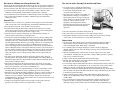
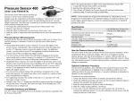
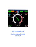
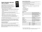
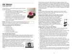
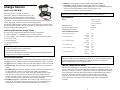
Charge Sensor (Order Code CRG-BTA) The Charge Sensor is used as an electronic electroscope. Unlike a traditional electroscope, the Charge Sensor can make quantitative measurements. Numerical measurements improve many electrostatics experiments, such as charging by induction, charging by friction and charging by contact. The sensor can also be used to measure charge polarity. An extremely high impedance voltage sensor with a 0.01µF input capacitor makes these measurements possible. The sensor has three operating ranges and a zeroing switch to discharge the input capacitor. Collecting Data with the Charge Sensor This sensor can be used with the following interfaces to collect data: Vernier LabQuest® as a standalone device or with a computer Vernier LabPro® with a computer, TI graphing calculator, or Palm® handheld Vernier Go!®Link Vernier EasyLink® Vernier SensorDAQ® CBL 2TM Here is the general procedure to follow when using the Charge Sensor: 1. Connect the Charge Sensor to the interface. 2. Start the data-collection software. 3. The software will identify the Charge Sensor and load a default data-collection setup. You are now ready to collect data. Data-Collection Software This sensor can be used with an interface and the following data-collection software. Logger Pro This computer program is used with LabQuest, LabPro, or Go!Link. Logger Lite This computer program is used with LabQuest, LabPro, or Go!Link. LabQuest App This program is used when LabQuest is used as a stand-alone device. EasyData App This calculator application for the TI-83 Plus and TI-84 Plus can be used with CBL 2, LabPro, Vernier EasyLink, CBR 2, and CBR. We recommend version 2.0 or newer, which can be downloaded from the Vernier web site, www.vernier.com/easy/easydata.html, and then transferred to the calculator. See the Vernier web site, www.vernier.com/calc/software/index.html for more information on the App and Program Transfer Guidebook. DataMate program Use DataMate with LabPro or CBL 2 and TI-73, TI-83, TI-84, TI-86, TI-89, and Voyage 200 calculators. See the LabPro and CBL 2 Guidebooks for instructions on transferring DataMate to the calculator. Data Pro This program is used with LabPro and a Palm handheld. LabVIEW National Instruments LabVIEW™ software is a graphical programming language sold by National Instruments. It is used with SensorDAQ and can be used with a number of other Vernier interfaces. See www.vernier.com/labview for more information. NOTE: This product is to be used for educational purposes only. It is not appropriate for industrial, medical, research, or commercial applications. Specifications 0.5 V ( 5 nC) 2 V ( 20 nC) 10 V ( 100 nC) 150 V 0.005 pA 0.1 s Ranges Maximum input Typical bias input current Instrument time constant Stored Calibration Values 0.5V setting in Volts 0.5V setting in nC 2 V setting in Volts 2 V setting in nC 10 V setting in Volts 10 V setting in nC slope intercept slope intercept slope intercept slope intercept slope intercept slope intercept 0.22 – 0.55 2.2 – 5.5 1.0 – 2.5 10.0 – 25.0 3.3 – 8.25 33.0 – 82.5 This sensor is equipped with circuitry that supports auto-ID. When used with LabQuest, LabPro, Go! Link, SensorDAQ, EasyLink, or CBL 2, the data-collection software identifies the sensor and uses pre-defined parameters to configure an experiment appropriate to the recognized sensor. How the Charge Sensor Works The Vernier Charge Sensor is an extremely high impedance voltage sensor with a 0.01 μF capacitor in series with the input. The capacitor will accumulate charge until the source’s voltage is reached, i.e. equilibrium is achieved. Small amounts of charge can be measured even though their initial potential is higher than the input range of the sensor. The input circuit also includes a 1 M resistor in series with the capacitor to protect the unit from large current surges. When used with a datacollection interface, the negative polarity (black) input lead is grounded to the computer. 2 Do I Need to Calibrate the Charge Sensor? No. You do not need to calibrate the Charge Sensor. We have set the sensor to match our stored calibration before shipping it. You can simply use the appropriate calibration file that is stored in your data-collection program from Vernier in any of these ways: 1. If you are using the Charge Sensor with a LabPro or CBL 2 interface, then a calibration is automatically loaded when the Charge Sensor is detected. 2. If you manually load an experiment or calibration file, choose the Charge Sensor. 3. Any version of the DataMate, EasyData, or DataPro App will automatically identify this sensor. General Tips When the sensor is stored, it is a good idea to short together to protect the leads in order to protect the sensor from high static potential that could damage the unit. Press the Reset button for a few seconds to zero the sensor. Pressing and releasing the Reset button with the leads connected to a voltage source such as a power supply or battery will cause an error in the reading and is not recommended, because it will short the supply as well. Since the sensor is capable of measuring very small amounts of charge, it is critical to begin experiments by zeroing the sensor. You must be careful when handling the leads or you may alter the readings with stray charge. The insulator on the clip lead quickly becomes oily from handling, and fingers often carry small amounts of charge at high potential that can easily leak through the insulator and affect your reading. The best way to minimize this is by grounding your fingers, or wearing a grounding strap on your wrist, to remove any charge before releasing the positive lead from its ground connection. Start recording data before removing the lead from ground so you will be aware if any stray charge accumulates before making your connection. When connecting to static sources (not a fixed voltage like a battery), the Reset button can be used while connected to a passive charge receptor. Make sure the output reads zero after reset. The sensor is not differential; therefore the negative (black) side is always at ground potential. The supplied cable is shielded and has a low leakage dielectric. When using other cables, the unit should be tested to make sure the cable does not allow excessive leakage currents The negative (black) lead is the ground connection. The effects of stray static charges will be minimized by connecting the black lead to a metal ground plane below your experiment, such as a sheet of aluminum foil. Synthetic clothing can carry significant charge, as can the experimenter’s body. Grounding the experimenter by using a ground strap on one wrist will help. When not using a Faraday Pail and ground plane, it helps to connect a metal cup to the positive (red) lead. This cup adds negligible capacitance to the system, but makes it easy to see induced or deposited charges. Insulate the cup from the ground plane using a glass jar or beaker. Plastic does not work well because it will accumulate stray charge quickly. Complete all experiments quickly. Due to leakage currents in the cable and apparatus, the reading will rarely be reliable after 15 seconds. 3 Tips for Use with a Faraday Pail and Ground Plane Use of this sensor is simplified with the aid of a Faraday Pail and ground plane such as found in the Vernier Electrostatics Kit. (See Accessories described below.) Since the sensor is capable of measuring very small amounts of charge, it is important to begin experiments by zeroing (resetting) the sensor. Simply press the Reset button on the sensor for a few seconds to zero the equipment. (Pressing the Reset button, internally shorts the leads, shorts the internal input capacitor and the internal integrator capacitor.) The sensor should be zeroed after initial power up. The sensor must be zeroed whenever a new range setting is chosen. During data collection, monitor the sensor reading. If an excess charge develops on the sensor, zero the sensor prior to a new data-collection run. Project ideas Use the sensor with a Faraday pail to investigate charging by induction. Bring a charged object near the pail. What charge is measured? Ground the pail and remove the charged object. What charge is measured? Use a Faraday pail to investigate charging by contact. Do this by dropping a charged object into the can. All of the charge on the object will be transferred to or induced in the can. Without a grounding strap, scuff your feet on carpet or pull off a sweater. Hold your hand near a Faraday pail. Do you induce a charge? What sign? Does a ground strap remove or reduce this effect? Charge various objects and determine the sign of the charge. Measure how quickly objects lose charge. Plot the charge as a function of time; this will take some minutes on a dry day. Use the Charge Sensor and Faraday Pail to observe the separation of charge when two strips of invisible tape are pulled apart. On two 3 inch pieces of tape, make a tab by folding over the top of each. Stick the combination to the table top. Pull the combination off the table and then pull the top strip off the bottom strip. Individually place each strip into the Faraday Pail to measure the charge. Simultaneously place them in the Pail to measure the charge. Charge a Faraday pail by contact on the inside; add more charge. How much charge can you add from the inside of the can? Can you add as much from the outside? Why? Use a second pail (not connected to the red lead as a detector) and charge it by induction. Do this by charging an insulating object, holding it inside the pail (inducing a charge on the outside of the can) and then briefly grounding the pail. 4 Remove the charged insulator, and you’ve got a charged pail. Measure the charge by testing it by induction, or by touching it to the inside of the detector pail. Many of these tips are based on suggestions from Robert Morse, Ph.D. Accessories Two accessory kits are available for the Charge Sensor are helpful in conducting a variety of experiments. Electrostatics Kit (ESK-CRG) The Electrostatics Kit is an accessory for the Vernier Charge Sensor. This kit allows students to perform a range of experiments in electrostatics. Experiments include Using Faraday’s Ice Pail Production of charge by friction Transfer of charge by contact Charging by Induction Quantitative and qualitative measurement of charge The kit includes Faraday Pail (aluminum can) Cage (metal wire cage) (2) Grounding Wires (2) Charge Producers Proof Plane Cotton cloth Ground Plane (flat metal sheet) Grounding Wrist Strap Square of wool (fabric) Square of vinyl (plastic pad) PVC rod (gray) Nylon rod (white) The key part to this kit is the Faraday Pail, Cage and Ground Plane. The Faraday Pail is used in the measurement of electrostatic charge on objects. Charged objects placed inside the Pail induce a charge that is detected by the Charge Sensor attached to the Pail. The sensor allows you to determine the magnitude and sign of the charge on the object. 5 High Voltage Electrostatics Kit (HVEK-CRG) The High Voltage Electrostatics Kits is an accessory for the Vernier Charge Sensor (order code CRG-BTA). Use it with a Faraday Pail, which is part of this kit, and the Charge Sensor to investigate the charge on a sphere. The current output of the High Voltage Source is extremely low, making it safe for electrostatic studies. Experiments include Investigate the distribution of charge on a sphere Transfer of charge on contact between two spheres Charging by Induction The kit includes Electrostatic High Voltage Source (output 750, 1500, 3000, 6000 VDC) Ground Wire Voltage Terminal Proof Plane Conducting Spheres (2) Warranty Vernier warrants this product to be free from defects in materials and workmanship for a period of five years from the date of shipment to the customer. This warranty does not cover damage to the product caused by abuse or improper use. 6 Vernier Software & Technology 13979 S.W. Millikan Way Beaverton, OR 97005-2886 Toll Free (888) 837-6437 (503) 277-2299 FAX (503) 277-2440 [email protected] www.vernier.com Rev.5/4/11 Logger Pro, Logger Lite, Vernier LabQuest, Vernier LabPro, Go! Link, Vernier EasyLink and other marks shown are our trademarks or registered trademarks in the United States.CBL 2 and CBL, TI-GRAPH LINK, and TI Connect are trademarks of Texas Instruments.All other marks not owned by us that appear herein are the property of their respective owners, who may or may not be affiliated with, connected to, or sponsored by us. Printed on recycled paper. 7 8