1
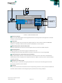
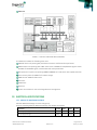
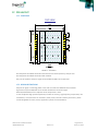
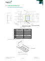
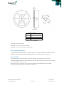
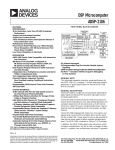
 Datasheet ORG12XX SERIES GNSS RECEIVER MODULES OriginGPS.com
Multi Hornet and Multi Hornetella ORG12XX Datasheet
Revision 3.0
Page 1 of 26
January 19, 2015
INDEX
1. 2. 3. 4. 5. 6. 7. 8. 9. 10. 11. 11.1. 11.2. 12. 12.1. 12.2. 13. 13.1. 13.2. 13.3. 13.4. 13.5. 14. 14.1. 15. 15.1. 15.2. 15.3. 16. 16.1. 16.2. 16.2.1. 16.2.2. 16.2.3. 16.2.4. 16.2.5. 16.3. 17. 17.1. 17.2. 18. 18.1. 18.2. 18.3. 19. 19.1. 19.2. 20. 20.1. 20.2. 20.3. 20.4. 20.5. 20.6. 20.7. SCOPE ................................................................................................................................................................ 4 DISCLAIMER ...................................................................................................................................................... 4 SAFETY INFORMATION ...................................................................................................................................... 4 ESD SENSITIVITY ................................................................................................................................................ 4 CONTACT INFORMATION .................................................................................................................................. 4 RELATED DOCUMENTATION .............................................................................................................................. 4 REVISION HISTORY ............................................................................................................................................ 4 GLOSSARY ......................................................................................................................................................... 5 ABOUT ORG12XX SERIES ................................................................................................................................... 6 ABOUT ORIGINGPS ............................................................................................................................................ 6 DESCRIPTION ..................................................................................................................................................... 7 FEATURES .......................................................................................................................................................... 7 ARCHITECTURE .................................................................................................................................................. 8 ELECTRICAL SPECIFICATIONS ........................................................................................................................... 10 ABSOLUTE MAXIMUM RATINGS ...................................................................................................................... 10 RECOMMENDED OPERATING CONDITIONS ..................................................................................................... 11 PERFORMANCE ............................................................................................................................................... 12 ACQUISITION TIMES ........................................................................................................................................ 12 SENSITIVITY ..................................................................................................................................................... 13 POWER CONSUMPTION .................................................................................................................................. 13 ACCURACY ....................................................................................................................................................... 13 DYNAMIC CONSTRAINS ................................................................................................................................... 14 POWER MANAGEMENT ................................................................................................................................... 14 POWER STATES ............................................................................................................................................... 14 EXTENDED FEATURES ...................................................................................................................................... 14 JAMMER BARRIER ........................................................................................................................................... 14 AUTONOMOUS A‐GPS ..................................................................................................................................... 14 PREDICTIVE A‐GPS ........................................................................................................................................... 14 INTERFACE ...................................................................................................................................................... 15 PAD ASSIGNMENT ........................................................................................................................................... 15 CONNECTIVITY ................................................................................................................................................ 15 POWER ............................................................................................................................................................ 15 HOST CONTROL INTERFACE ............................................................................................................................. 16 RF INPUT – ORG1208 ....................................................................................................................................... 17 HOST DATA INTERFACE ................................................................................................................................... 17 SENSORS INTERFACE ....................................................................................................................................... 18 TYPICAL APPLICATION CIRCUIT ........................................................................................................................ 19 PCB LAYOUT .................................................................................................................................................... 20 FOOTPRINT ...................................................................................................................................................... 20 DESIGN RESTRICTIONS .................................................................................................................................... 20 OPERATION ..................................................................................................................................................... 21 STARTING THE MODULE .................................................................................................................................. 21 VERIFYING THE MODULE HAS STARTED .......................................................................................................... 21 SHUTTING DOWN THE MODULE ..................................................................................................................... 21 SOFTWARE FUNCTIONS ................................................................................................................................... 21 NMEA OUTPUT MESSAGES .............................................................................................................................. 21 NMEA INPUT MESSAGES ................................................................................................................................. 21 HANDLING INFORMATION .............................................................................................................................. 22 PRODUCT PACKAGING AND DELIVERY ............................................................................................................. 22 MOISTURE SENSITIVITY ................................................................................................................................... 23 ASSEMBLY ....................................................................................................................................................... 23 REWORK .......................................................................................................................................................... 24 ESD SENSITIVITY .............................................................................................................................................. 24 COMPLIANCES ................................................................................................................................................. 24 SAFETY INFORMATION .................................................................................................................................... 25 Multi Hornet and Multi Hornetella ORG12XX Datasheet
Revision 3.0
Page 2 of 26
January 19, 2015
20.8. 21. 21.1. 21.2. DISPOSAL INFORMATION ................................................................................................................................ 25 MECHANICAL SPECIFICATIONS ........................................................................................................................ 25 ORG1218 MODULE .......................................................................................................................................... 25 ORG1208 MODULE .......................................................................................................................................... 26 TABLE INDEX TABLE 1 – RELATED DOCUMENTATION ............................................................................................................................. 4 TABLE 2 – REVISION HISTORY ............................................................................................................................................ 4 TABLE 3 – ABSOLUTE MAXIMUM RATINGS ..................................................................................................................... 11 TABLE 4 – RECOMMENDED OPERATING CONDITIONS .................................................................................................... 12 TABLE 5 – ACQUISITION TIMES ....................................................................................................................................... 12 TABLE 6 – SENSITIVITY ..................................................................................................................................................... 13 TABLE 7 – POWER CONSUMPTION .................................................................................................................................. 13 TABLE 8 – ACCURACY ...................................................................................................................................................... 13 TABLE 9 – DYNAMIC CONSTRAINS ................................................................................................................................... 14 TABLE 10 – ORG12XX SERIES MODULE PIN‐OUT ............................................................................................................. 15 TABLE 11 – SPI TIMING .................................................................................................................................................... 18 TABLE 12 – NMEA PROTOCOL OUTPUT MESSAGES ......................................................................................................... 21 TABLE 13 – NMEA PROTOCOL INPUT MESSAGES ............................................................................................................ 21 TABLE 14 – REEL DIMENSIONS ........................................................................................................................................ 23 TABLE 15 – ORG1218 MECHANICAL SUMMARY .............................................................................................................. 25 TABLE 16 – ORG1208 MECHANICAL SUMMARY .............................................................................................................. 26 FIGURE INDEX FIGURE 1 – ORG1218 ARCHITECTURE ............................................................................................................................... 8 FIGURE 2 – ORG1208 ARCHITECTURE ............................................................................................................................... 9 FIGURE 3 – GNSS SoC FUNCTIONAL BLOCK DIAGRAM ..................................................................................................... 10 FIGURE 4 – UART INTEGRITY ........................................................................................................................................... 17 FIGURE 5 – SPI TIMING .................................................................................................................................................... 18 FIGURE 6 – ORG1218 UART INTERFACE CIRCUIT ............................................................................................................. 19 FIGURE 7 – ORG1208 UART INTERFACE CIRCUIT ............................................................................................................. 19 FIGURE 8 – FOOTPRINT ................................................................................................................................................... 20 FIGURE 9 – CARRIER ........................................................................................................................................................ 22 FIGURE 10 – CARRIER DIMENSIONS [mm] ....................................................................................................................... 22 FIGURE 11 – MODULE POSITION ..................................................................................................................................... 22 FIGURE 12 – REEL ............................................................................................................................................................ 23 FIGURE 13 – RECOMMENDED SOLDERING PROFILE ........................................................................................................ 24 FIGURE 15 – ORG1208 MECHANICAL DRAWING ............................................................................................................. 26 Multi Hornet and Multi Hornetella ORG12XX Datasheet
Revision 3.0
Page 3 of 26
January 19, 2015
1. SCOPE This document describes the features and specifications of Multi Hornet ORG1218 and Multi Hornetella ORG1208 GNSS Receiver Modules. 2. DISCLAIMER All trademarks are properties of their respective owners. Performance characteristics listed in this document do not constitute a warranty or guarantee of product performance. OriginGPS assumes no liability or responsibility for any claims or damages arising out of the use of this document, or from the use of integrated circuits based on this document. OriginGPS assumes no liability or responsibility for unintentional inaccuracies or omissions in this document. OriginGPS reserves the right to make changes in its products, specifications and other information at any time without notice. OriginGPS reserves the right to conduct, from time to time, and at its sole discretion, firmware upgrades. As long as those FW improvements have no material change on end customers, PCN may not be issued. OriginGPS navigation products are not recommended to use in life saving or life sustaining applications. 3. SAFETY INFORMATION Improper handling and use can cause permanent damage to the product. 4. ESD SENSITIVITY This product is ESD sensitive device and must be handled with care. 5. CONTACT INFORMATION Support ‐ [email protected] or Online Form Marketing and sales ‐ [email protected] Web – www.origingps.com 6. RELATED DOCUMENTATION № DOCUMENT NAME 1 Micro Spider – ORG4475 Evaluation Kit Datasheet 2 Micro Spider – ORG4475 Product Change Notification 3 Spider and Hornet ‐ Software User Manual for CSR® based receivers 4 Spider and Hornet ‐ NMEA Protocol Reference Manual for CSR® based receivers 5 Spider and Hornet ‐ One Socket Protocol Reference Manual for CSR® based receivers 6 Spider and Hornet ‐ Host Interface Application Note 7 Spider and Hornet ‐ Low Power Modes Application Note 8 Spider and Hornet ‐ Jammer Detector and Remover Application Note TABLE 1 – RELATED DOCUMENTATION 7. REVISION HISTORY REVISION DATE CHANGE DESCRIPTION A00 February 1, 2013 First release 2.0 January 14, 2015 Format update 3.0 January 19, 2015 Reel packaging quantities TABLE 2 – REVISION HISTORY Multi Hornet and Multi Hornetella ORG12XX Datasheet
Revision 3.0
Page 4 of 26
January 19, 2015
8. GLOSSARY A‐GNSS Assisted GNSS BPF Band Pass Filter CE European Community conformity mark CGEE™ Client Generated Extended Ephemeris CMOS Complementary Metal‐Oxide Semiconductor COMPASS PRC GNSS (same as BDS BeiDou‐2 Navigation Satellite System) EGNOS European Geostationary Navigation Overlay Service EMC Electro‐Magnetic Compatibility ESD Electro‐Static Discharge EVB Evaluation Board EVK Evaluation Kit FCC Federal Communications Commission GALILEO EU GNSS GLONASS Global Navigation Satellite System GNSS Global Navigation Satellite System GPS Global Positioning System I²C Inter‐Integrated Circuit IC Integrated Circuit ISO International Organization for Standardization LDO Low Dropout regulator LGA Land Grid Array LNA Low Noise Amplifier MSAS Multi‐functional Satellite Augmentation System MSL Moisture Sensitivity Level NFZ™ Noise‐Free Zones System NMEA National Marine Electronics Association MEMS MicroElectroMechanical Systems PCB Printed Circuit Board PPS Pulse Per Second QZSS Quasi‐Zenith Satellite System REACH Registration, Evaluation, Authorisation and Restriction of Chemical substances RF Radio Frequiency RHCP Right‐Hand Circular Polarized RoHS Restriction of Hazardous Substances directive ROM Read‐Only Memory RTC Real‐Time Clock SAW Surface Acoustic Wave SBAS Satellite‐Based Augmentation Systems SGEE™ Server Generated Extended Ephemeris SIP System In Package SMD Surface Mounted Device SMT Surface‐Mount Technology SOC System On Chip SPI Serial Peripheral Interface TCXO Temperature‐Compensated Crystal Oscillator TTFF Time To First Fix TTL Transistor‐Transistor Logic UART Universal Asynchronous Receiver/Transmitter WAAS Wide Area Augmentation System Multi Hornet and Multi Hornetella ORG12XX Datasheet
Revision 3.0
Page 5 of 26
January 19, 2015
9. ABOUT ORG12XX SERIES The ORG12XX series module has been designed to address markets where an ability to autonomously acquire position fix from multiple satellite constellations must be coupled with superior sensitivity and low power consumption. The ORG12XX series module is a miniature GNSS (Global Navigation Satellite System) GPS/GALILEO/GLONASS receiver that continuously tracks all satellites in view and provides real‐time positioning data in industry’s standard NMEA format. The ORG12XX series module is able to decode extremely weak satellite signals simultaneously from GPS and GLONASS thereby offering best‐in‐class positioning availability, unparalleled accuracy and extremely fast fixes under challenging signal conditions, such as in built‐up urban areas, dense foliage or even indoor. Featuring OriginGPS proprietary Noise‐Free Zone System™ technology the ORG12XX series module offers the ultimate in high sensitivity satellite navigation combined with high immunity. The ORG12XX series module is a complete SiP (System‐in‐Package) featuring miniature SMD (Surface Mount Device) technology footprint designed to commit unique integration features for high volume, low power and cost sensitive applications. Internal GNSS SoC (System‐on‐Chip) incorporating high‐performance ARM9 microprocessor and sophisticated GNSS firmware keeps positioning payload off the host allowing integration in embedded solutions even with low computing resources. The ORG12XX series incorporate 2 modules: 1. The ORG1218 – fully integrated GNSS module with on‐board antenna. The ORG1218 GPS receiver module is pin and footprint compatible to the OriginGPS ORG1418 module. 2. The ORG1208 – fully integrated GNSS module with on‐board RF connector. The ORG1208 GPS receiver module is pin and footprint compatible to the OriginGPS ORG1408 module. 10. ABOUT ORIGINGPS OriginGPS is a world leading designer, manufacturer and supplier of miniature positioning modules, antenna modules and antenna solutions. OriginGPS modules introduce unparalleled sensitivity and noise immunity by incorporating Noise Free Zone system (NFZ™) proprietary technology for faster position fix and navigation stability even under challenging satellite signal conditions. Founded in 2006, OriginGPS is specializing in development of unique technologies that miniaturize RF modules, thereby addressing the market need for smaller wireless solutions. Multi Hornet and Multi Hornetella ORG12XX Datasheet
Revision 3.0
Page 6 of 26
January 19, 2015
11. DESCRIPTION OriginGPS has researched and enhanced the performance of standard GPS receivers in real life applications. Case study of the specifications of key components through involvement in R&D effort of major vendors derived in highest performance in industry’s smallest footprint parts available. These carefully selected key components resulted in higher sensitivity, faster position fix, navigation stability and operation robustness under rapid environmental changes creating hard‐to‐achieve laboratory performance in heavy‐duty environment. 11.1. FEATURES Autonomous operation OriginGPS Noise Free Zone System (NFZ™) technology Active antenna on‐board – ORG1218 Active or passive antenna input – ORG1208 Fully integrated with: GNSS SAW Filter, GNSS LNA, TCXO, RTC Crystal, RF Shield, RAM, Flash Memory, Power Management Unit 50Ω miniature RF connector, Load Switch – ORG1208 GPS/GLONASS/GALILEO/COMPASS1 multi‐GNSS RF and Baseband SBAS (WAAS, EGNOS, MSAS, QZSS) support 32 tracking channels Sensitivity: ‐162dBm during Tracking TTFF: < 1s under Hot Start conditions Accuracy: < 1.5m CEP (50%) Timing Accuracy: < 30ns Update rate: up to 10Hz Autonomous A‐GPS for non‐networked devices Predictive A‐GPS for connected devices Jammer Barrier through proprietary filtering and removal Low power mode: < 0.1mW during Backup state ARM9 208MHz microprocessor system UART or SPI host interface Programmable baud rate and messages rate Secondary UART for RTCM‐104 Auxiliary I²C bus for MEMS sensors Single voltage supply: 3 – 3.6V Backup supply option: 1.6 – 3.6V Small footprint: 17mm x 17mm Surface Mount Device (SMD) Operating temperature range: ‐40°C to 85°C Multi Hornet and Multi Hornetella ORG12XX Datasheet
Revision 3.0
Page 7 of 26
January 19, 2015
FCC and CE certified Pb‐Free RoHS/REACH compliant ISO/TS 16949 manufacturing standard Notes: 1. Future modification 11.2. ARCHITECTURE VCC
3 – 3.6V
VBAT
1.6 – 3.6V
V 1V8
PMU
1.8V
GNSS Engine
RF Power
WAKEUP
STDBY
Microstrip Patch
Filtering Antenna
RESET
SAW Filter
I/O buffers
LNA
UART / SPI
HOST
1PPS
RTC Crystal
TCXO
FIGURE 1 – ORG1218 ARCHITECTURE Microstrip Patch Antenna OriginGPS integrated microstrip patch antenna element collects GNSS signals from the medium. GNSS LNA (Low Noise Amplifier) The integrated LNA amplifies the GNSS signal to meet RF down converter input threshold. Noise Figure optimized design was implemented to provide maximum sensitivity. Multi Hornet and Multi Hornetella ORG12XX Datasheet
Revision 3.0
Page 8 of 26
January 19, 2015
VANT
1.8 – 6V
VCC
3 – 3.6V
VBAT
1.6 – 3.6V
V1V8
PMU
1.8V
GNSS Engine
WAKEUP
Load
Switch
WAKEUP
STDBY
RESET
I/O buffers
Connector
SAW Filter
UART / SPI
HOST
1PPS
RTC Crystal
TCXO
FIGURE 2 – ORG1208 ARCHITECTURE Antenna Connector Signals from the GNSS satellites are being delivered from receiving antenna through W.FL® standard miniature coaxial connector. Load Switch Load switch provides control over DC bias voltage supply for active antenna. When the ORG1208 module is in Standby or Backup state no power is dissipated on active antenna. GNSS SAW (Surface Acoustic Wave) Filter Band‐Pass SAW filter eliminates out‐of‐band signals that may interfere to GNSS reception. Voltage Regulator Voltage regulator provides stable supply for GNSS RF front‐end. The design of this block was optimized for low ripple, low quiescent current and high PSRR. TCXO (Temperature Compensated Crystal Oscillator) Highly stable 26 MHz oscillator controls the down conversion process in RF block of the GNSS SoC. Characteristics of this component are important factors for higher sensitivity, shorter TTFF and better navigation stability. RTC (Real Time Clock) crystal Tuning fork quartz crystal with very tight specifications is necessary for maintaining Hot Start and Warm Start capabilities of the module. RF Shield RF enclosure avoids external interference from compromising sensitive circuitry inside the module. RF shield also blocks module’s internal high frequency emissions from being radiated. Multi Hornet and Multi Hornetella ORG12XX Datasheet
Revision 3.0
Page 9 of 26
January 19, 2015
GNSS SoC FIGURE 3 – GNSS SoC FUNCTIONAL BLOCK DIAGRAM The GNSS SoC includes the following main units: GNSS RF block incorporating LNA, dual down converter and fractional‐N synthesizer GNSS IF block incorporating dual IF BPF centered on 4.092MHz for GPS/GALILEO signals and on 8.57MHz for GLONASS signals, and dual ADC with 3‐bit quantization Microprocessor system incorporating 208MHz ARM946 core and Vector Interrupted Controller Flash memory block of 16Mbit for firmware storage RAM block of 256KB for data cache RTC block UART block SPI block Power control block for internal voltage domains management 12. ELECTRICAL SPECIFICATIONS 12.1. ABSOLUTE MAXIMUM RATINGS Absolute Maximum Ratings are stress ratings only. Stresses exceeding Absolute Maximum Ratings may damage the module. Parameter Symbol
Min Max Units Power Supply Voltage VCC ‐0.3 +3.63 V Backup Supply Voltage VBAT ‐0.3 +3.63 V Multi Hornet and Multi Hornetella ORG12XX Datasheet
Revision 3.0
Page 10 of 26
January 19, 2015
Antenna Supply Voltage VANT ‐0.5 +6.0 V IANT ‐ 200 mA I/O Voltage VIO ‐0.3 +3.6 V I/O Source/Sink Current IIO ‐2 +2 mA I1V8 ‐ 20 mA ‐ ‐10 ‐ +25 ‐ +25 V(ESD) ‐1 +1 kV Power Dissipation PD ‐ 300 mW Storage temperature TST ‐55 +125 °C TLEAD ‐ +260 °C Antenna Supply Current ORG1208 1.8V Source Current fIN = 1570MHz÷1620MHz RF Input Power fIN < 1525MHz PRF_IN fIN > 1670MHz ESD Rating All pads Lead temperature (10 sec. @ 1mm from case) dBm TABLE 3 – ABSOLUTE MAXIMUM RATINGS 12.2. RECOMMENDED OPERATING CONDITIONS Functional operation above the Recommended Operating Conditions is not implied. Extended exposure to stresses above the Recommended Operating Conditions may affect module reliability. Parameter Power Supply Voltage Symbol Operation/Pad VCC VCC Acquisition Power Supply Current Backup Supply Voltage Backup Supply Current ICC
VBAT IBAT Tracking Mode Test GPS Min Typ Max Units 3.0 3.3 3.6 V 55 mA GPS+GLONASS ‐130dBm Outdoor 75 mA GPS VCC = 3.3V 35 mA GPS+GLONASS TAMB = 25°C 55 mA 1 mA 1.6 3.6 V 1 mA Standby VBAT Acquisition Tracking VBAT = 1.8V 1 mA Standby TAMB = 25°C 60 µA Backup 60 µA Antenna Supply Voltage VANT VANT 1.8 5.5 V Antenna Supply Current IANT VANT 100 mA 1.8V Output Voltage V1V8 V1V8 1.77 1.80 1.83 V 1.8V Output Current I1V8 V1V8 20 mA Input Voltage Low State VIL UART / SPI ‐0.3 +0.8 V RESET, STANDBY
‐0.3 +0.48 V Input Voltage High State VIH UART / SPI +2.0 +3.6 V RESET, STANDBY
+0.8 +1.2 V Multi Hornet and Multi Hornetella ORG12XX Datasheet
Revision 3.0
Page 11 of 26
January 19, 2015
Output Voltage Low State VOL Output Voltage High State VOH UART/SPI/1PPS +0.4 V WAKEUP +0.2 V UART/SPI/1PPS +2.9 3.2 V WAKEUP +1.0 V Input Leakage Current IIN(leak) UART / SPI ‐10 10 µA Output Leakage Current IOUT(lea
UART/SPI/1PPS ‐10 +10 µA Input Capacitance CIN All pads 7 pF Input Impedance ZIN 50 Ω RLIN f0 = 1575.5 MHz Input Return Loss RF Input ‐10 dB ‐40 +25 +85 °C 5 95 % Operating Temperature Relative Humidity TAMB RH ‐40°C °
TABLE 4 – RECOMMENDED OPERATING CONDITIONS 13. PERFORMANCE 13.1. ACQUISITION TIMES TTFF (Time To First Fix) – is the period of time from the module power‐up till valid navigation solution. Hot Start Hot Start results from software reset after a period of continuous navigation or a return from a short idle period that was preceded by a period of continuous navigation. During Hot Start all critical data (position, velocity, time, and satellite ephemeris) is valid to the specified accuracy and available in RAM. Warm Start Warm Start typically results from user‐supplied position and time initialization data or continuous RTC operation with an accurate last known position available in RAM. In this state, position and time data are present and valid, but ephemeris data validity has expired. Cold Start Cold Start acquisition results when satellite ephemeris, last good position and time data are unknown. Aided Start Aided Start is a method of effectively reducing the TTFF by making every start Hot or Warm. TTFF Hot Start < 1s Aided Start1 < 10s Warm Start Cold Start GPS < 34s GPS+GLONASS < 31s GPS < 35s GPS+GLONASS < 33s Signal Reacquisition Test Condition Signal Level Outdoor ‐130dBm < 1s TABLE 5 – ACQUISITION TIMES Multi Hornet and Multi Hornetella ORG12XX Datasheet
Revision 3.0
Page 12 of 26
January 19, 2015
13.2. SENSITIVITY Operation Signal Level Tracking ‐162 dBm Navigation ‐160 dBm (Deep Aided ‐155 dBm Cold Start ‐146 dBm TABLE 6 – SENSITIVITY 13.3. POWER CONSUMPTION Operation Mode Power Consumption GPS 180mW GPS+GLONASS 245mW GPS 115mW GPS+GLONASS 180mW Standby ‐ 3mW Backup ‐ 0.1mW Acquisition Tracking TABLE 7 – POWER CONSUMPTION 13.4. ACCURACY Method CEP (50%) Mode Accuracy GPS < 2.5m GPS+SBAS < 2m GPS+GLONASS < 1.5m GPS < 5m GPS+SBAS < 4m GPS+GLONASS < 3m GPS < 4m GPS+SBAS < 3.5m GPS+GLONASS < 2.5m GPS < 7.5m GPS+SBAS < 6.5m GPS+GLONASS < 5m Test Condition Signal Level Outdoor, 24‐hr static ‐130dBm Horizontal 2dRMS (95%) Position VEP (50%) Vertical 2dRMS (95%) Velocity Horizontal 50% < 0.01m/s Outdoor, 30m/s ‐130dBm Heading 50% < 0.010 Outdoor, 30m/s ‐130dBm Time 1 PPS < 40ns Outdoor, 24‐hr static TABLE 8 – ACCURACY Multi Hornet and Multi Hornetella ORG12XX Datasheet
Revision 3.0
Page 13 of 26
January 19, 2015
‐130dBm 13.5. DYNAMIC CONSTRAINS MAXIMUM Velocity 515 m/s Acceleration 4g Altitude 18,288 m 1,000 knots 60,000 ft. TABLE 9 – DYNAMIC CONSTRAINS 14. POWER MANAGEMENT 14.1. POWER STATES Full Power state (Acquisition/Tracking) The module stays in full power until a position solution is made and estimated to be reliable. During the acquisition, processing is more intense than during tracking, thus consuming more power. Standby state In this state the RF block of the module is powered off and baseband clock is stopped. During Standby state all outputs are in high‐impedance state. Backup state In this state the RF block and the baseband block are completely powered off leaving only the RTC block running and Battery‐Backed RAM sustained. Upon exit Backup state of duration less than 4 hours since last valid navigation solution the ORG12XX series module will perform Hot Start acquisition trial. 15. EXTENDED FEATURES 15.1. JAMMER BARRIER Jamming detection is processed by frequency spread and analysis of correlation results and jamming contribution calculation. Jamming detector is effective only against continuous narrow band interference signals. Jamming removal is done by dynamic notch filter alignment over GPS/GALILEO and GLONASS frequency bands. Jamming remover has programmable notch filter central frequency and bandwidth. 15.2. AUTONOMOUS A‐GPS Autonomous A‐GPS allows shorter TTFF by providing predicted (synthetic) ephemeris data created within a lost host system from previously received broadcast ephemeris. Autonomous A‐GPS is capable for up to 5‐day span prediction. 15.3. PREDICTIVE A‐GPS Predictive A‐GPS allows shorter TTFF by using a model downloaded from server. Predictive A‐GPS is suitable for networked applications, while communication channel is immaterial. Predictive A‐GPS is capable for up to 7‐day span prediction. Multi Hornet and Multi Hornetella ORG12XX Datasheet
Revision 3.0
Page 14 of 26
January 19, 2015
16. INTERFACE 16.1. PAD ASSIGNMENT Pad Name Description Direction Full Power Standby Backup 1 RX UART Receive
Input High Hi‐Z Keep Low 2.0V – 3.6V 2 TX UART Transmit
Output High Hi‐Z Keep Low 3.3V 3 VBAT
Secondary Power Power On On On 4 SCK SPI Clock Input Low Hi‐Z Keep Low SPI Chip Select Input High Hi‐Z Keep Low SPI Data Out
Output High Hi‐Z Keep Low 3.3V compatible CS
5 6 SDO Notes 1.6V – 3.6V 2.0V – 3.6V 7 VANT Active Antenna Bias Power
Leave floating on ORG1218 or on ORG1208 with passive antenna 8 VCC System Power Power On On Off 3.0V – 3.6V 9 V1V8 1.8V Source Power On On Off Do not power this pad. 10 GND System Ground Power 11 GND System Ground Power 12 GND System Ground Power 13 GND System Ground Power 14 GND System Ground Power 15 WAKEUP Power Status Output High Low Low 1.2V compatible 16 RESET Asynchronous Reset Input High High Low Do not drive 17 STANDBY Power State Control
Input High Low Low Do not drive 18 DR_SDA I²C Serial Data / RTCM RX Bi‐dir High Hi‐Z Keep Low 19 DR_SCL I²C Serial Clock / RTCM TX Output High Hi‐Z Keep Low 20 ADC ADC / Odometer input Keep Low 0V – 1.8V Input 3.3V compatible 21 1PPS UTC Time Mark Output Low Hi‐Z Keep Low 3.3V compatible 22 SDI SPI Data In Input
High Hi‐Z Keep Low 2.0V – 3.6V TABLE 10 – ORG12XX SERIES MODULE PIN‐OUT 16.2. CONNECTIVITY 16.2.1. POWER The ORG12XX series module can be operated from single unregulated power source, i.e supplied directly from a battery, since the module has internal voltage converters. Main power VCC power input is for main power supply. VCC power supply range is 3V to 3.6V DC. Typical VCC is 3.3V. Power supply current consumption varies according to the processor load and satellite acquisition. Typical ICC current is 55mA during acquisition. Peak ICC current is 75 mA. Voltage ripple below 50mVP‐P allowed for frequency between 100KHz and 3MHz. Higher voltage ripple may compromise the module’s sensitivity performance. Multi Hornet and Multi Hornetella ORG12XX Datasheet
Revision 3.0
Page 15 of 26
January 19, 2015
Backup power VBAT power input is for backup power supply. VBAT power supply range is 1.6V to 3.6V DC. Typical IBAT current in Backup state is 60µA. Typical IBAT current in Full Power state is 1mA. It is recommended to keep the VBAT power supply on all the time in order to maintain GNSS SoC RTC block active and RAM sustained for fastest possible TTFF under Hot Start or Warm Start definitions. When the VBAT is off prior to consecutive power‐up, GNSS data and clock are discarded, configuration settings are reset to factory default, and the receiver performs Cold Start. While an application requires continuous navigation VBAT may be externally connected to VCC. During Hibernate state VBAT may be powered either by battery, or by super capacitor. Antenna power – ORG1208 VANT power input is for active antenna bias through integrated low‐loss load switch. VANT power supply range is 1.8V to 5.5V DC according to antenna specifications. Maximum IANT current is 150mA. Antenna bias is internally controlled by the GNSS SoC and switched off during Standby or Backup states. VANT may be externally connected to VCC, while module and antenna are in same voltage domain. While using passive antenna, do not apply voltage on this input. 1.8V power source V1V8 power supply provides regulated 1.8V voltage source. Maximum I1V8 continuous output current is 20mA. Ground All Ground pads should be connected to the main Ground plane by shortest possible traces or multiple vias. 16.2.2. HOST CONTROL INTERFACE STANDBY input STANDBY control input is used to switch the receiver from Full Power into Standby state. A logic low level applied on this input transfers and holds the module in Standby state. A release of this input from logic low level exits the Standby state back to Full Power. STANDBY input is active low and has internal pull‐up resistor of 10kΩ. Do not drive this input high. Do not connect if not in use. RESET input The Power‐On‐Reset (POR) is generated internally in the module when VBAT is applied. Manual reset option is available through RESET pad. RESET input should be asserted externally during the first power‐up when VBAT power supply is applied prior to VCC power supply. RESET input asserted during the operation clears the RTC block and discards configuration settings. RESET signal should be logical low level for at least 1µs. RESET input is active low and has internal pull‐up resistor of 10kΩ. Do not drive this input high. Do not connect if not in use. WAKEUP output WAKEUP output is used to flag the power state of the module. A logical low level on this output indicates that the module is in Standby or Backup state. Multi Hornet and Multi Hornetella ORG12XX Datasheet
Revision 3.0
Page 16 of 26
January 19, 2015
A logical high level on this output indicates that the module is in Full Power state. In addition WAKEUP output can be used to control auxiliary devices. Wakeup output is LVCMOS 1.2V compatible. Do not connect if not in use. 1PPS output The pulse‐per‐second (PPS) output provides a pulse signal for timing purposes. The rising edge of the 1PPS output signal is synchronized to full UTC second with <30ns accuracy. Typical RMS jitter on the rising edge of the 1PPS output signal is <30ns. Default pulse length (high state) is 500ms. By default, the UTC time output message is generated after 1PPS rising edge. The exact time between the 1PPS and UTC time message output depends on message rate, message queue and communication baud rate. Pulse length, polarity and phase are configurable by an NMEA input command. 1PPS output is LVCMOS 3.3V compatible. Do not connect if not in use. 16.2.3. RF INPUT – ORG1208 The ORG1208 module supports active and passive antennas. The antenna input impedance is 50Ω. DC bias voltage for active antennas is provided via VANT pad. Mating plug for RF antenna connector is Hirose W.FL , I‐PEX MHF III or Sunridge MCD series. Recommended active antenna NF ≤ 1.8 dB, net gain excluding cable loss 10dB ≤ G ≤ 25dB. Leave VANT pad floating while using passive antenna. Contact OriginGPS for passive antenna selection. 16.2.4. HOST DATA INTERFACE The ORG12XX series module has 2 types of interface ports to connect to host: UART and SPI. UART The module has a 2‐wire UART port: TX used for GPS data reports. Output logic high voltage level is LVCMOS 3.3V. RX used for control over receiver configuration. Input logic high voltage level is 2V to 3.6V. Operation: The UART performs bit‐by‐bit transmitting and receiving in 8‐bit octets when module is active. On the transmit side 1 start bit, 8 data bits and 1 stop bit followed by next character or idle line. On the receive side 1 start bit, 8 data bits, 1 stop bit or longer is accepted. FIGURE 4 – UART INTEGRITY Because UART transmission is asynchronous and sampled by the receiver, both sides require closely match bit‐rate clocks, and that data bit waveform and timing distortion at the receiver should be limited. The default protocol is NMEA@115,200bps. The baud rate and message configuration can be changed by an input command. SPI The SPI (Serial to Peripheral Interface) is a master/slave synchronous serial bus that consists of 4 signals: Serial Clock (SCK) from master to slave. Serial Data Out (also called Master Out Slave In or MOSI) from master. Multi Hornet and Multi Hornetella ORG12XX Datasheet
Revision 3.0
Page 17 of 26
January 19, 2015
Serial Data In (also called Master In Slave Out or MISO) from slave. Chip Select (CS) from master. The host interface SPI of the module is a slave mode SPI. Output logic high voltage level is LVCMOS 3.3V. Inputs are 3.6V tolerant. FIGURE 5 – SPI TIMING Symbol Parameter Min Max Units tCLK SCK Time Period TBA tCSS nCS Setup Time TBA TBA tCLK tCS nCS High Time TBA TBA tCLK tWH SCK High Time TBA TBA tCLK tWL SCK Low Time TBA TBA tCLK tCSH nCS Hold Time TBA TBA tCLK tSU Data In Setup Time TBA TBA tCLK tH Data In Hold Time TBA TBA tCLK tV Output Valid TBA TBA tCLK tHO Output Hold Time TBA TBA tCLK tDIS Output Disable Time TBA TBA tCLK ns TABLE 11 – SPI TIMING 16.2.5. SENSORS INTERFACE Dead Reckoning (DR) I²C bus The ORG12XX series module master mode I²C interface provides support for Dead Reckoning. This auxiliary bus has 2 lines, DR_SCL and DR_SDA, both are pseudo open‐drain and require external pull‐up resistors. The interface supports required sensor instruments for dead reckoning applications such as gyros, accelerometers, compasses or other sensors that can be operated over the I²C bus. The Dead Reckoning (DR) algorithms perform a sensor data fusion with the satellite signal measurements. Do not connect to this bus if the feature is not in use. ADC / Odometer input The ORG12XX series module can be programmed to use a dedicated GPIO either as odometer ticking counter, or as Analog‐to‐Digital Converter (ADC). ADC specifications are: 10‐bit SAR, 1MSPS, effective full scale voltage range 0V – 1.4V. Do not connect to this input if the feature is not in use. Multi Hornet and Multi Hornetella ORG12XX Datasheet
Revision 3.0
Page 18 of 26
January 19, 2015
16.3. TYPICAL APPLICATION CIRCUIT VCC=3.0-3.6V
Vback
Vcc
1
D1
BAT54C
SOT 23
3
2
VBACK=2-3.6V
9
3
V1V8
18
19
20
nSTANDBY
WAKEUP_GPS
nRESET_GPS
R1
0R
ON_OFF 17
R2
0R
WAKEUP 15
R3
0R
nRESET 16
8
VBAT
7
VCC
R4
VEN
100R
DR_SDA
DR_SCL
ADC
21
1PPS
STANDBY
18pF
1PPS
U1
WAKEUP
5
4
6
22
CS
SCK
SDO
SDI
RESET
11
12
13
2
1
TX
RX
GND1 GND2 GND3 GND4 GND5
10
1PPS_GPS
C1
C3
R5
220R
R6
220R
TX_GPS
18pF
TX
RX
C2
14
RX_GPS
18pF
INPUTS ARE 3.6V TOLERANT
FIGURE 6 – ORG1218 UART INTERFACE CIRCUIT Vcc
VCC=3.0-3.6V
VANT=1.8-5.5V
VBACK=2-3.6V
Vant
FB1
1
2
Vback
ASSEMBLE FERRITE BEAD FOR ACTIVE ANTENNA
D1
BAT54C
SOT 23
9
3
V1V8
18
19
20
nSTANDBY
WAKEUP_GPS
nRESET_GPS
R1
0R
ON_OFF 17
R2
0R
WAKEUP 15
R3
0R
nRESET 16
3
1K @ 100MHz
8
VBAT
VCC
7
R4
VANT
100R
DR_SDA
DR_SCL
ADC
STANDBY
1PPS
CS
SCK
SDO
SDI
RESET
GND1 GND2 GND3 GND4 GND5
11
21
1PPS
18pF
U1
WAKEUP
10
1PPS_GPS
C1
12
13
TX
RX
5
4
6
22
2
1
C3
R5
220R
R6
220R
TX_GPS
18pF
TX
RX
14
C2
RX_GPS
18pF
INPUTS ARE 3.6V TOLERANT
FIGURE 7 – ORG1208 UART INTERFACE CIRCUIT Multi Hornet and Multi Hornetella ORG12XX Datasheet
Revision 3.0
Page 19 of 26
January 19, 2015
17. PCB LAYOUT 17.1. FOOTPRINT TOP VIEW
0.669
16.99
0.596
15.14
0.050
1.27
12
11
0.669
16.99
0.669
16.99
0.490
12.45
0.033
0.84
1
22
0.042
1.07
0.050
1.27
inch
millimeter
FIGURE 8 – FOOTPRINT Ground pad at the middle should be connected to main Ground plane by multiple vias. Ground pad at the middle should be solder masked. Silk print of module’s outline is highly recommended for SMT visual inspection. 17.2. DESIGN RESTRICTIONS Keep out of signal or switching power traces and vias under the ORG12XX series module. Signal traces to/from ORG12XX series module should have minimum length. Recommended distance from adjacent active components is 3mm. In case of adjacent high speed components, like CPU or memory, high frequency components, like transmitters, clock resonators or oscillators, metal planes, like LCD or battery enclosures, please contact OriginGPS for more precise, application specific recommendations. Multi Hornet and Multi Hornetella ORG12XX Datasheet
Revision 3.0
Page 20 of 26
January 19, 2015
18. OPERATION 18.1. STARTING THE MODULE When power is first applied, the GNSS SoC of the module access boot‐loader for firmware initialization. Firmware is executed autonomously, and the module starts searching for GNSS satellites. 18.2. VERIFYING THE MODULE HAS STARTED The module WAKEUP output will go logic level high indicating the GNSS SoC has started. The module will output standard NMEA strings starting ‘$’ at 115,200bps. baud rate. 18.3. SHUTTING DOWN THE MODULE Transferring the module into Backup state can be forced by main VCC power supply removal. 19. SOFTWARE FUNCTIONS The module supports standard NMEA‐0183 protocol with proprietary extensions. 19.1. NMEA OUTPUT MESSAGES Message Description
$GPRMC $GPGGA $GPVTG $GPGSV $GLGSV $GPGSA $GNGSA $PTSTMSBAS Time, date, position, course and speed data in GPS mode or in GLONASS+GPS mode Time, position and fix type data in GPS mode or in GLONASS+GPS modes Course and ground speed data in GPS mode or in GLONASS+GPS mode GPS satellite in view, SV ID, Elevation, Azimuth and SNR value
GLONASS satellite in view, SV ID, Elevation, Azimuth and SNR value
GPS operating mode, satellites used in the position solution and DOP values GLONASS operating mode, satellites used in the position solution and DOP values SBAS satellite in view, SV ID, Elevation, Azimuth and SNR value
TABLE 12 – NMEA PROTOCOL OUTPUT MESSAGES 19.2. NMEA INPUT MESSAGES Message ID Message $PSTMSETPAR
$PSTMGETPAR
$PSTMRESTOREPAR
$PSTMCOLD
$PSTM $PSTM
$PSTM
Proprietary Message
Proprietary Message
Proprietary Message
Proprietary Message
Proprietary Message
Proprietary Message
Proprietary Message
TABLE 13 – NMEA PROTOCOL INPUT MESSAGES Multi Hornet and Multi Hornetella ORG12XX Datasheet
Revision 3.0
Page 21 of 26
January 19, 2015
20. HANDLING INFORMATION 20.1. PRODUCT PACKAGING AND DELIVERY TOP
PAD 1
FEEDDIRECTION
FIGURE 9 – CARRIER A0 B0 K0 F P1 S0 W ORG1218 ORG1208 20.50 ± 0.1
20.50 ± 0.1
07.30 ± 0.1
14.20 ± 0.1
24.00 ± 0.1
28.40 ± 0.1
32.00 ± 0.3
18.00 ± 0.1
18.00 ± 0.1
03.60 ± 0.1
14.20 ± 0.1
24.00 ± 0.1
28.40 ± 0.1
32.00 ± 0.3
FIGURE 10 – CARRIER DIMENSIONS [mm] Carrier material: Conductive Polystyrene Feed direction
FIGURE 11 – MODULE POSITION Multi Hornet and Multi Hornetella ORG12XX Datasheet
Revision 3.0
Page 22 of 26
January 19, 2015
ØA FIGURE 12 – REEL 330.00 ± 0.85 ØN 60.00 ± 0.5 W1 33.00 ± 0.5 W2 39.00 ± 0.5 TABLE 14 – REEL DIMENSIONS Reel material: Antistatic Plastic ORG1218: Each reel contains 175 modules. ORG1208: Each reel contains 250 or 500 modules. 20.2. MOISTURE SENSITIVITY The ORG12XX series module is MSL 3 designated device according to IPC/JEDEC J‐STD‐033B standard. Module in sample or bulk package should be baked prior to assembly at 125°C for 48 hours. 20.3. ASSEMBLY The ORG12XX series module supports automatic assembly and reflow soldering processes. Recommended thickness of the solder paste stencil is 5mil, while openings in the pad mask are 100% to ensure sufficient solder volume. Reflow soldering of the module is according to IPC/JEDEC J‐STD‐020D standard for LGA SMD. Avoid reflow soldering process while module is facedown. Multi Hornet and Multi Hornetella ORG12XX Datasheet
Revision 3.0
Page 23 of 26
January 19, 2015
FIGURE 13 – RECOMMENDED SOLDERING PROFILE Recommended peak reflow temperature is 250°C for 10 sec. for Pb‐Free RoHS solder paste. Absolute Maximum reflow temperature is 260°C for 10 sec. 20.4. REWORK If localized heating is required to rework or repair the module, precautionary methods are required to avoid exposure to high temperatures that can result in permanent damage. 20.5. ESD SENSITIVITY The module is ESD sensitive device and should be handled with care. 20.6. COMPLIANCES The following standards are applied on the production of the ORG12XX series module: IPC‐6011/6012 Class2 for PCB manufacturing IPC‐A‐600 Class2 for PCB inspection IPC‐A‐610D Class2 for SMT acceptability The ORG12XX series modules are manufactured in ISO 9001:2000 accredited facilities. The ORG12XX series modules are manufactured in ISO 14001:2004 accredited facilities. The ORG12XX series modules are designed, manufactured and handled to comply with and according to Pb‐Free/RoHS Directive 2002/95/EC on the restriction of the use of certain hazardous substances in electrical and electronic equipment. The ORG12XX series modules are manufactured in facilities under EU REACH regulation. The ORG12XX series modules comply with the following EMC standards: EU CE EN55022:06+A1(07), Class B US FCC 47CFR Part 15:09, Subpart B, Class B JAPAN VCCI V‐3/2006.04 Multi Hornet and Multi Hornetella ORG12XX Datasheet
Revision 3.0
Page 24 of 26
January 19, 2015
20.7. SAFETY INFORMATION Improper handling and use can cause permanent damage to the device. There is also the possible risk of personal injury from mechanical trauma or shocking hazard. 20.8. DISPOSAL INFORMATION The product should not be treated as household waste. For more detailed information about recycling electronic components, please contact your local waste management authority. 21. MECHANICAL SPECIFICATIONS The module has miniature packaging in LGA SMD footprint sized 17mm x 17mm. The module is built on miniature PCB enclosed with metallic shield box. The module has 22 SMT pads with copper base/ENIG plating on the bottom side. The package of the module has been optimized for automated pick and place assembly and reflow soldering processes. 21.1. ORG1218 MODULE TOP VIEW
SIDE VIEW
BOTTOM VIEW
18.0 ± 0.1
12
1
22
Pin 1
1.0 ± 0.1
All dimensions are in millimeters
FIGURE 14 – ORG1218 MECHANICAL DRAWING Dimensions Length Width Height Weight mm 18.0 ± 0.1 18.0 ± 0.1 5.8 ± 0.1 gr
5 inch 0.709 ± 0.004 0.709 ± 0.004 0.228 ± 0.004 oz 0.18 TABLE 15 – ORG1218 MECHANICAL SUMMARY Multi Hornet and Multi Hornetella ORG12XX Datasheet
1 ± 0.1
11
Revision 3.0
Page 25 of 26
January 19, 2015
1.27
17.0 ± 0.1
18.0 ± 0.1
5.8 ± 0.1
17.0 ± 0.1
21.2. ORG1208 MODULE TOP VIEW
SIDE VIEW
BOTTOM VIEW
0.669 ± 0.008
17.0 ± 0.2
0.669 ± 0.008
17.0 ± 0.2
11
12
0.025
0.64
0.05
1.27
0.669 ± 0.008
17.0 ± 0.2
Ø 0.165 ± 0.008
4.2 ± 0.2
0.087 ± 0.004
2.2 ± 0.1
0.669 ± 0.008
17.0 ± 0.2
0.264 ± 0.004
6.7 ± 0.1
0.603
15.32
1
22
Pad 1 marking
0.025
0.64
inch
millimeter
FIGURE 15 – ORG1208 MECHANICAL DRAWING Dimensions Length Width Height Weight mm 17.0 ± 0.2 17.0 ± 0.2 2.2 ± 0.1 gr
1.4 inch 0.669 ± 0.008 0.669 ± 0.008 0.088 ± 0.004 oz 0.1 TABLE 16 – ORG1208 MECHANICAL SUMMARY Multi Hornet and Multi Hornetella ORG12XX Datasheet
Revision 3.0
Page 26 of 26
January 19, 2015