1
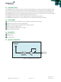
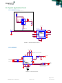
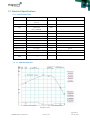
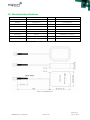
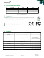
SPIDER’S ANTENNAS (ORG9805)
ACTIVE ANTENNA
Datasheet
OriginGPS.com
ORG9805 Antenna Datasheet
Revision 3.0
Page 1 of 11
June 21, 2015
INDEX
Datasheet............................................................................................................................................................................ 1
1.
SCOPE ................................................................................................................................................................... 3
2.
DISCLAIMER .......................................................................................................................................................... 3
3.
SAFETY INFORMATION ......................................................................................................................................... 3
4.
ESD SENSITIVITY .................................................................................................................................................... 3
5.
CONTACT INFORMATION...................................................................................................................................... 3
6.
RELATED DOCUMENTATION ................................................................................................................................. 3
7.
REVISION HISTORY ................................................................................................................................................ 4
8.
GLOSSARY ............................................................................................................................................................. 4
9.
ABOUT SPIDER FAMILY ......................................................................................................................................... 5
10.
ABOUT SPIDER'S ANTENNAS................................................................................................................................. 5
11.
ABOUT ORIGINGPS ............................................................................................................................................... 5
12.
DESCRIPTION ........................................................................................................................................................ 6
13.
FEATURES.............................................................................................................................................................. 6
14.
BENEFITS ............................................................................................................................................................... 6
15.
BLOCK DIAGRAM .................................................................................................................................................. 6
16.
Typical Application Circuit .................................................................................................................................... 7
16.1. ORG447X series .................................................................................................................................................... 7
16.2. ORG1408 ............................................................................................................................................................... 7
17.
Electrical Specifications ........................................................................................................................................ 8
17.1. Characteristic Data ............................................................................................................................................... 8
17.2. Characteristic Curves ............................................................................................................................................ 8
18.
Mechanical Specifications .................................................................................................................................... 9
19.
Environmental Specifications ............................................................................................................................. 10
20.
Compliance ......................................................................................................................................................... 10
21.
Reliability ............................................................................................................................................................ 10
22.
Safety Information .............................................................................................................................................. 11
23.
Disposal Information .......................................................................................................................................... 11
24.
Product Labeling ................................................................................................................................................. 11
TABLE INDEX
TABLE 1 – RELATED DOCUMENTATION ................................................................................................................................ 3
TABLE 2 – REVISION HISTORY ............................................................................................................................................... 4
TABLE 3 – ELECTRICAL SPECIFICATIONS................................................................................................................................ 8
TABLE 4 – MECHANICAL DATA .............................................................................................................................................. 9
TABLE 5 – ENVIRONMENTAL DATA..................................................................................................................................... 10
TABLE 6 – RELIABILITY DATA ............................................................................................................................................... 10
FIGURE INDEX
FIGURE 1 – ORG9805 BLOCK DIAGRAM................................................................................................................................ 6
FIGURE 2 – ORG447X SERIES CIRCUIT ................................................................................................................................... 7
FIGURE 3 – ORG1408 CIRCUIT .............................................................................................................................................. 7
FIGURE 6 – LNA ..................................................................................................................................................................... 8
FIGURE 7 – MECHANICAL DATA ............................................................................................................................................ 9
FIGURE 8 – LABELING INFORMATION ................................................................................................................................. 11
ORG9805 Antenna Datasheet
Revision 3.0
Page 2 of 11
June 21, 2015
1. SCOPE
This document describes the features and specifications of Spider’s Antennas ORG9805 Antenna.
2. DISCLAIMER
All trademarks are properties of their respective owners.
Performance characteristics listed in this document do not constitute a warranty or guarantee of product
performance. OriginGPS assumes no liability or responsibility for any claims or damages arising out of the
use of this document, or from the use of integrated circuits based on this document.
OriginGPS assumes no liability or responsibility for unintentional inaccuracies or omissions in this document.
OriginGPS reserves the right to make changes in its products, specifications and other information at any
time without notice.
OriginGPS reserves the right to conduct, from time to time, and at its sole discretion, firmware upgrades.
As long as those FW improvements have no material change on end customers, PCN may not be issued.
OriginGPS navigation products are not recommended to use in life saving or life sustaining applications.
3. SAFETY INFORMATION
Improper handling and use can cause permanent damage to the product.
4. ESD SENSITIVITY
This product is ESD sensitive device and must be handled with care.
5. CONTACT INFORMATION
Support - [email protected] or Online Form
Marketing and sales - [email protected]
Web – www.origingps.com
6. RELATED DOCUMENTATION
№
DOCUMENT NAME
1
Micro Spider – ORG4475 Evaluation Kit Datasheet
2
Micro Spider – ORG4475 Product Change Notification
3
Spider and Hornet - Software User Manual for CSR® based receivers
4
Spider and Hornet - NMEA Protocol Reference Manual for CSR® based receivers
5
Spider and Hornet - One Socket Protocol Reference Manual for CSR® based receivers
6
Spider and Hornet - Host Interface Application Note
7
Spider and Hornet - Low Power Modes Application Note
8
Spider and Hornet - Jammer Detector and Remover Application Note
9
Spider and Hornet - Client Generated Extended Ephemeris Application Note
10
Spider and Hornet - Server Generated Extended Ephemeris Application Note
11
Spider and Hornet - Ephemeris Push Application Note
TABLE 1 – RELATED DOCUMENTATION
ORG9805 Antenna Datasheet
Revision 3.0
Page 3 of 11
June 21, 2015
7. REVISION HISTORY
REVISION
DATE
CHANGE DESCRIPTION
A00
November 9, 2011
First release
2.0
January 14, 2015
Format update, content update according to PCN
3.0
June 21, 2015
Updated Electrical Characteristics (GLONASS support)
TABLE 2 – REVISION HISTORY
8. GLOSSARY
A-GNSS Assisted GNSS
BPF Band Pass Filter
CE European Community conformity mark
CGEE™ Client Generated Extended Ephemeris
CMOS Complementary Metal-Oxide Semiconductor
COMPASS PRC GNSS (same as BDS BeiDou-2 Navigation Satellite System)
EGNOS European Geostationary Navigation Overlay Service
EMC Electro-Magnetic Compatibility
ESD Electro-Static Discharge
EVB Evaluation Board
EVK Evaluation Kit
FCC Federal Communications Commission
GALILEO EU GNSS
GLONASS Global Navigation Satellite System
GNSS Global Navigation Satellite System
GPS Global Positioning System
I²C Inter-Integrated Circuit
IC Integrated Circuit
ISO International Organization for Standardization
LDO Low Dropout regulator
LGA Land Grid Array
LNA Low Noise Amplifier
MSAS Multi-functional Satellite Augmentation System
MSL Moisture Sensitivity Level
NFZ™ Noise-Free Zones System
NMEA National Marine Electronics Association
MEMS MicroElectroMechanical Systems
PCB Printed Circuit Board
PPS Pulse Per Second
QZSS Quasi-Zenith Satellite System
REACH Registration, Evaluation, Authorisation and Restriction of Chemical substances
RF Radio Frequiency
RHCP Right-Hand Circular Polarized
RoHS Restriction of Hazardous Substances directive
ROM Read-Only Memory
RTC Real-Time Clock
SAW Surface Acoustic Wave
SBAS Satellite-Based Augmentation Systems
SGEE™ Server Generated Extended Ephemeris
SIP System In Package
SMD Surface Mounted Device
ORG9805 Antenna Datasheet
Revision 3.0
Page 4 of 11
June 21, 2015
SMT Surface-Mount Technology
SOC System On Chip
SPI Serial Peripheral Interface
TCXO Temperature-Compensated Crystal Oscillator
TTFF Time To First Fix
TTL Transistor-Transistor Logic
UART Universal Asynchronous Receiver/Transmitter
WAAS Wide Area Augmentation System
9. ABOUT SPIDER FAMILY
OriginGPS GNSS receiver modules have been designed to address markets where size, weight, stand-alone
operation, highest level of integration, power consumption and design flexibility - all are very important.
OriginGPS’ Spider family breaks size barrier, offering the industry’s smallest fully-integrated, highly-sensitive
GPS and GNSS modules.
Spider family features OriginGPS' proprietary NFZ™ technology for high sensitivity and noise immunity even
under marginal signal condition, commonly found in urban canyons, under dense foliage or when the
receiver’s position in space rapidly changes.
Spider family enables the shortest TTM (Time-To-Market) with minimal design risks.
Just connect an antenna and power supply on a 2-layer PCB.
10. ABOUT SPIDER'S ANTENNAS
L1 Ceramic Patch Antennas – For ultimate compatibility and best-in-class performance use our Spider’s
modules together with Spider’s Antennas.
11. ABOUT ORIGINGPS
OriginGPS is a world leading designer, manufacturer and supplier of miniature positioning modules, antenna
modules and antenna solutions.
OriginGPS modules introduce unparalleled sensitivity and noise immunity by incorporating Noise Free Zone
system (NFZ™) proprietary technology for faster position fix and navigation stability even under challenging
satellite signal conditions.
Founded in 2006, OriginGPS is specializing in development of unique technologies that miniaturize RF
modules, thereby addressing the market need for smaller wireless solutions.
ORG9805 Antenna Datasheet
Revision 3.0
Page 5 of 11
June 21, 2015
12. DESCRIPTION
The ORG9805 External Active Antenna incorporates high-efficiency ceramic patch antenna element, high
out-of-band rejection band-pass Surface Acoustic Wave (SAW) filter, low Noise Figure and high gain Low
Noise Amplifier (LNA), enclosed in plastic case, with coaxial cable terminated by standard SMA-type plug.
The ORG9805 Active Antenna with highest GPS-band performance and notch filtering for out-of band signals
provides exceptional sensitivity, high selectivity and noise immunity.
The ORG9805 Active Antenna is built of highest quality materials and components.
The ORG9805 Active Antenna is the perfect match to the OriginGPS GPS receiver modules.
13. FEATURES
Antenna element with high efficiency for excellent coverage of GPS satellites
SAW filter for rejection of out-of-band signals
LNA with low Noise Figure and high gain for high sensitivity
Plastic case with magnetic base
RG-174 flexible coaxial cable of 5m length
SMA-type gold plated plug
14. BENEFITS
High performance
Compact size
Easy integration
15. BLOCK DIAGRAM
Microstrip Patch
Antenna
RF out
DC in
SAW Filter
LNA
FIGURE 1 – ORG9805 BLOCK DIAGRAM
ORG9805 Antenna Datasheet
Revision 3.0
Page 6 of 11
June 21, 2015
16. Typical Application Circuit
16.1. ORG447X series
Active Antenna Bias
Vant
R1
100K
Dn
U2
6
W AKEU P_GPS
Gn
BI AS_EN
Gp
Vant
2
Sn
Sp
1
4
5
C1
3
18pF
Dp
ON
NTZD3155CT1G
SOT-563
GPS_VCC
L1
MURATA
LQG15HS27NJ02
27nH
J1
RF Connector
U1
GPS Engine
1
2
3
RF_IN
12
Vcc
GND
RF_IN
GND
CTS
RTS
TX
nRESET_GPS 5
ON /OF F _GPS 9
W AKEU P_GPS 4
1PP S_GPS
10
RESET
RX
ON_OFF
DR_SCL
WAKEUP
DR_SDA
1PPS
RTC
NEP
GND
17
14
6
nC TS_GPS
7
nR TS_GPS
11
TX_GPS
8
RX_GPS
16
15
13
ORIGINGPS
ORG447X
LGA77
FIGURE 2 – ORG447X SERIES CIRCUIT
16.2. ORG1408
Vcc
Vant
FB1
ASSEMBLE FERRITE BEAD FOR ACTIVE ANTENNA
1K @ 100MHz
9
3
V1V8
18
19
20
ON_OFF_GPS
WAKEUP_GPS
nRESET_GPS
R1
R2
R3
0R
ON _OFF 17
0R
WAKEUP 15
0R
nR ESET 16
8
VTX
VCC
7
R4
VANT
DR_SDA
DR_SCL
EIT
1PPS_GPS
C1
18pF
1PPS
ON_OFF
21
1PPS
U1
WAKEUP
5
SE 4
SCK
6
SDO 22
SDI
RESET
GND1 GND2 GND3 GND4 GND5
10
100R
11
12
13
2
TX
1
RX
TX
RX
R5
100R
R6
220R
TX_GPS
RX_GPS
14
TX HAS LEVEL TRANSLATOR AS SET BY VTX
INPUTS ARE 3.6V TOLERANT
Connector
FIGURE 3 – ORG1408 CIRCUIT
ORG9805 Antenna Datasheet
Revision 3.0
Page 7 of 11
June 21, 2015
17. Electrical Specifications
17.1. Characteristic Data
Parameter
Value
Unit
Notes
Frequency Range
1575.42 ± 5
1610 ± 8
MHz
VSWR
1.5:1
BW
10 for GPS
20 for GLONASS
MHz
Peak Gain
5 (min)
dBic
Polarization
R.H.C.P
impedance
50
Ω
LNA freq. range
1595± 25
MHz
LNA Gain
30 (typ)
dB
LNA Noise Figure
1.5 (max)
dB
LNA DC Voltage
3-5
V
supplied via coaxial cable
LNA DC Current
11.5 (typ)
mA
@3.0V
LNA Output VSWR
2.0 (typ)
LNA Impedance
50
Ω
@output
Cable Insertion
Loss
1.2 (typ)
dB/m
RF cable RG174
On 70mm x 70mm Ground Plane
without cable loss
@output
TABLE 3 – ELECTRICAL SPECIFICATIONS
17.1.1. LNA Characteristic
FIGURE 4 – LNA
ORG9805 Antenna Datasheet
Revision 3.0
Page 8 of 11
June 21, 2015
18. Mechanical Specifications
Parameter
Value
Unit
Notes
Size ( L x W x T )
48.6 x 39.2 x 15.2
mm
tolerance: ± 0.5mm
Weight
106 (approx.)
g
including cable
Housing
PC
Color
Black
Mounting
Magnetic base
Orientation
Horizontal surface
Cable Type
RG-174
Cable Length
5
Connector Type
SMA Plug
diameter: 2.7 ± 0.1mm
m
Gold plated
TABLE 4 – MECHANICAL DATA
ORG9805 Antenna Datasheet
Revision 3.0
Page 9 of 11
June 21, 2015
19. Environmental Specifications
Parameter
Value
Notes
Operating Temperature
-40°C to +85°C
Storage Temperature
-40°C to +85°C
Humidity
5% ~ 95% RH
@ operating temp.
Weatherproof
IP66
dustproof and waterproof
TABLE 5 – ENVIRONMENTAL DATA
20. Compliance
The ORG9805 External Active Antennas are manufactured and handled to comply with and
according to Pb-Free/RoHS Directive 2002/95/EC on the restriction of the use of certain
hazardous substances in electrical and electronic equipment.
The ORG9805 Active Antennas are manufactured in ISO 9001:2000 accredited facilities.
The ORG9805 Active Antennas are manufactured in ISO 14001:2004 accredited facilities.
The ORG9805 Active Antennas comply with the following EMC standards:
EU CE EN55022:06+A1(07), Class B
US FCC 47CFR Part 15:09, Subpart B, Class B
21. Reliability
Parameter
Description
Pass Criteria
Drop Test
Place antenna on set 1.5m height
Drop 5 times
1. No visible damage
2. Electrical perf. is satisfying
Vibration Test
Sine sweep 5 – 55 – 5 Hz, 1 octave/min
Amplitude = 1.5mm, Acceleration = 2g
Crossover freq. = 18Hz
Hold time = 2hr.
1. No visible damage
2. Electrical perf. is satisfying
Humidity
60°C, 95% RH, 96hr.
1. No visible damage
2. Electrical perf. is satisfying
Thermal Shock
+80°C (30 min) → 5 min → -40°C (30 min)
10 cycles
1. No visible damage
2. Electrical perf. is satisfying
High Temperature Resistance
+85°C, 96hr.
1. No visible damage
2. Electrical perf. is satisfying
Low Temperature Resistance
- 40°C, 96hr.
1. No visible damage
2. Electrical perf. is satisfying
TABLE 6 – RELIABILITY DATA
ORG9805 Antenna Datasheet
Revision 3.0
Page 10 of 11
June 21, 2015
22. Safety Information
Improper handling or use can cause permanent damage to the device.
There is also the possible risk of personal injury from mechanical trauma or shocking hazard.
23. Disposal Information
The product should not be treated as household waste.
For more detailed information about recycling electronic components, please contact your local waste
management authority.
24. Product Labeling
ORG9805
GPS Active Antenna
FIGURE 6 – LABELING INFORMATION
ORG9805 Antenna Datasheet
Revision 3.0
Page 11 of 11
June 21, 2015