1
User Manual
Ultraware Software
Catalog Number 2098-UWCPRG
Important User Information
Solid-state equipment has operational characteristics differing from those of electromechanical equipment. Safety
Guidelines for the Application, Installation and Maintenance of Solid State Controls (publication SGI-1.1 available from
your local Rockwell Automation sales office or online at http://www.rockwellautomation.com/literature/) describes some
important differences between solid-state equipment and hard-wired electromechanical devices. Because of this difference,
and also because of the wide variety of uses for solid-state equipment, all persons responsible for applying this equipment
must satisfy themselves that each intended application of this equipment is acceptable.
In no event will Rockwell Automation, Inc. be responsible or liable for indirect or consequential damages resulting from the
use or application of this equipment.
The examples and diagrams in this manual are included solely for illustrative purposes. Because of the many variables and
requirements associated with any particular installation, Rockwell Automation, Inc. cannot assume responsibility or
liability for actual use based on the examples and diagrams.
No patent liability is assumed by Rockwell Automation, Inc. with respect to use of information, circuits, equipment, or
software described in this manual.
Reproduction of the contents of this manual, in whole or in part, without written permission of Rockwell Automation,
Inc., is prohibited.
Throughout this manual, when necessary, we use notes to make you aware of safety considerations.
WARNING: Identifies information about practices or circumstances that can cause an explosion in a hazardous
environment, which may lead to personal injury or death, property damage, or economic loss.
ATTENTION: Identifies information about practices or circumstances that can lead to personal injury or death,
property damage, or economic loss. Attentions help you identify a hazard, avoid a hazard, and recognize the
consequence
SHOCK HAZARD: Labels may be on or inside the equipment, for example, a drive or motor, to alert people that
dangerous voltage may be present.
BURN HAZARD: Labels may be on or inside the equipment, for example, a drive or motor, to alert people that
surfaces may reach dangerous temperatures.
IMPORTANT
Identifies information that is critical for successful application and understanding of the product.
Allen-Bradley, Kinetix, MicroLogix, Rockwell Software, Rockwell Automation, TechConnect, Ultra3000, and Ultra5000 are trademarks of Rockwell Automation, Inc.
Trademarks not belonging to Rockwell Automation are property of their respective companies.
Rockwell Automation Publication 2098-UM001G-EN-P - February 2011
2
Summary of Changes
This manual contains new and updated information.
New and Updated
Information
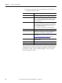
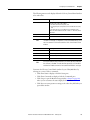
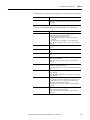
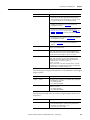
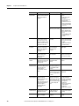
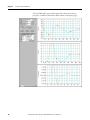
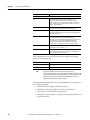
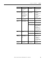
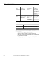
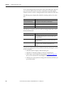
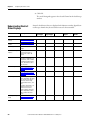
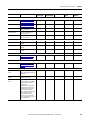
This table lists the changes made to this revision.
Topic
Pages
Chapter 5 - Configuring the Kinetix 3 Drive added.
221…297
Appendix A - Ultraware Software Updates adds Version 1.80 notes.
339
Rockwell Automation Publication 2098-UM001G-EN-P - February 2011
3
Summary of Changes
4
Rockwell Automation Publication 2098-UM001G-EN-P - February 2011
Table of Contents
Preface
About This Publication. . . . . . . . . . . . . . . . . . . . . . . . . . . . . . . . . . . . . . . . . . .
Who Should Use this Manual . . . . . . . . . . . . . . . . . . . . . . . . . . . . . . . . . . . . .
Conventions Used in This Manual . . . . . . . . . . . . . . . . . . . . . . . . . . . . . . . .
Additional Resources . . . . . . . . . . . . . . . . . . . . . . . . . . . . . . . . . . . . . . . . . . . . .
11
11
11
12
Chapter 1
Before You Begin
Introduction. . . . . . . . . . . . . . . . . . . . . . . . . . . . . . . . . . . . . . . . . . . . . . . . . . . . .
About Ultraware Software . . . . . . . . . . . . . . . . . . . . . . . . . . . . . . . . . . . . . . . .
Download Ultraware Software . . . . . . . . . . . . . . . . . . . . . . . . . . . . . . . . . . . .
Using Online Help . . . . . . . . . . . . . . . . . . . . . . . . . . . . . . . . . . . . . . . . . . . . . . .
How Ultraware Software Works . . . . . . . . . . . . . . . . . . . . . . . . . . . . . . . . . .
Understanding the Graphical User Interface. . . . . . . . . . . . . . . . . . . . . . . .
Workspace Window . . . . . . . . . . . . . . . . . . . . . . . . . . . . . . . . . . . . . . . . . .
Output Window . . . . . . . . . . . . . . . . . . . . . . . . . . . . . . . . . . . . . . . . . . . . .
Client Area . . . . . . . . . . . . . . . . . . . . . . . . . . . . . . . . . . . . . . . . . . . . . . . . . .
Main Menubar . . . . . . . . . . . . . . . . . . . . . . . . . . . . . . . . . . . . . . . . . . . . . . .
Toolbars . . . . . . . . . . . . . . . . . . . . . . . . . . . . . . . . . . . . . . . . . . . . . . . . . . . . .
Status Bar. . . . . . . . . . . . . . . . . . . . . . . . . . . . . . . . . . . . . . . . . . . . . . . . . . . .
Motion Library Dialog . . . . . . . . . . . . . . . . . . . . . . . . . . . . . . . . . . . . . . .
Starting Ultraware Software. . . . . . . . . . . . . . . . . . . . . . . . . . . . . . . . . . . . . . .
Opening an Ultraware File . . . . . . . . . . . . . . . . . . . . . . . . . . . . . . . . . . . .
Serial Port Settings . . . . . . . . . . . . . . . . . . . . . . . . . . . . . . . . . . . . . . . . . . .
Upgrading Drive Firmware . . . . . . . . . . . . . . . . . . . . . . . . . . . . . . . . . . . . . . .
13
13
14
14
14
15
16
17
18
19
19
20
20
21
21
22
22
Chapter 2
Common Commands for Ultra
Drive Configuration
Introduction. . . . . . . . . . . . . . . . . . . . . . . . . . . . . . . . . . . . . . . . . . . . . . . . . . . . .
Opening Ultraware Software . . . . . . . . . . . . . . . . . . . . . . . . . . . . . . . . . . . . . .
Creating, Opening and Saving Ultraware Files . . . . . . . . . . . . . . . . . . . . . .
Creating a New Ultraware File . . . . . . . . . . . . . . . . . . . . . . . . . . . . . . . .
Opening an Existing Ultraware File . . . . . . . . . . . . . . . . . . . . . . . . . . . .
Saving an Ultraware File . . . . . . . . . . . . . . . . . . . . . . . . . . . . . . . . . . . . . .
Creating a New Drive . . . . . . . . . . . . . . . . . . . . . . . . . . . . . . . . . . . . . . . . . . . .
Importing and Exporting a Drive . . . . . . . . . . . . . . . . . . . . . . . . . . . . . . . . . .
Exporting a Drive. . . . . . . . . . . . . . . . . . . . . . . . . . . . . . . . . . . . . . . . . . . . .
Importing a Drive . . . . . . . . . . . . . . . . . . . . . . . . . . . . . . . . . . . . . . . . . . . .
Working in the Workspace Window . . . . . . . . . . . . . . . . . . . . . . . . . . . . . .
Cut . . . . . . . . . . . . . . . . . . . . . . . . . . . . . . . . . . . . . . . . . . . . . . . . . . . . . . . . .
Copy . . . . . . . . . . . . . . . . . . . . . . . . . . . . . . . . . . . . . . . . . . . . . . . . . . . . . . . .
Paste . . . . . . . . . . . . . . . . . . . . . . . . . . . . . . . . . . . . . . . . . . . . . . . . . . . . . . . .
Delete . . . . . . . . . . . . . . . . . . . . . . . . . . . . . . . . . . . . . . . . . . . . . . . . . . . . . . .
Drag and Drop . . . . . . . . . . . . . . . . . . . . . . . . . . . . . . . . . . . . . . . . . . . . . . .
Rockwell Automation Publication 2098-UM001G-EN-P - February 2011
23
24
25
25
26
27
28
28
28
29
30
30
31
31
32
33
5
Table of Contents
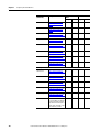
Chapter 3
Configuring the Ultra3000 Drive Introduction . . . . . . . . . . . . . . . . . . . . . . . . . . . . . . . . . . . . . . . . . . . . . . . . . . . . . 37
Configuring the Ultra3000 Drive . . . . . . . . . . . . . . . . . . . . . . . . . . . . . . . . . . 38
Configuring Properties for the Ultra3000 Drive . . . . . . . . . . . . . . . . . 39
Understanding the Ultra3000 Drive Branch . . . . . . . . . . . . . . . . . . . . . . . . 41
Velocity Control Panel Window . . . . . . . . . . . . . . . . . . . . . . . . . . . . . . . 50
Current Control Panel Window . . . . . . . . . . . . . . . . . . . . . . . . . . . . . . . 52
Current Control Panel Window . . . . . . . . . . . . . . . . . . . . . . . . . . . . . . . 52
Indexing Control Panel . . . . . . . . . . . . . . . . . . . . . . . . . . . . . . . . . . . . . . . 54
Drive Report . . . . . . . . . . . . . . . . . . . . . . . . . . . . . . . . . . . . . . . . . . . . . . . . . 57
Switching the SERCOS Interface . . . . . . . . . . . . . . . . . . . . . . . . . . . . . . 58
Understanding the Analog Window . . . . . . . . . . . . . . . . . . . . . . . . . . . . . . . 59
Understanding the Preset Window . . . . . . . . . . . . . . . . . . . . . . . . . . . . . . . . 62
Understanding the Follower Window . . . . . . . . . . . . . . . . . . . . . . . . . . . . . . 64
Understanding the Indexing Window . . . . . . . . . . . . . . . . . . . . . . . . . . . . . . 66
Understanding the Homing Window . . . . . . . . . . . . . . . . . . . . . . . . . . . . . . 70
Understanding the Motor Window . . . . . . . . . . . . . . . . . . . . . . . . . . . . . . . . 73
Understanding the Tuning Window . . . . . . . . . . . . . . . . . . . . . . . . . . . . . . . 77
Autotuning Window . . . . . . . . . . . . . . . . . . . . . . . . . . . . . . . . . . . . . . . . . 80
Manual Position Tuning Window . . . . . . . . . . . . . . . . . . . . . . . . . . . . . 82
Manual Velocity Tuning Window . . . . . . . . . . . . . . . . . . . . . . . . . . . . . 84
Understanding the Encoders Window . . . . . . . . . . . . . . . . . . . . . . . . . . . . . 86
Motor Diagnostics . . . . . . . . . . . . . . . . . . . . . . . . . . . . . . . . . . . . . . . . . . . . 89
Understanding the Digital Inputs Window . . . . . . . . . . . . . . . . . . . . . . . . . 95
Understanding the Digital Outputs Window . . . . . . . . . . . . . . . . . . . . . . . 99
Understanding the Analog Outputs Window . . . . . . . . . . . . . . . . . . . . . . 103
Understanding the Monitor . . . . . . . . . . . . . . . . . . . . . . . . . . . . . . . . . . . . . . 105
Understanding the Oscilloscope Window . . . . . . . . . . . . . . . . . . . . . . . . . 108
Channel Setup Window. . . . . . . . . . . . . . . . . . . . . . . . . . . . . . . . . . . . . . 111
Understanding Ultra3000 with DeviceNet . . . . . . . . . . . . . . . . . . . . . . . . 112
Understanding Ultra3000 Status . . . . . . . . . . . . . . . . . . . . . . . . . . . . . . . . . 118
Understanding the Faults Window . . . . . . . . . . . . . . . . . . . . . . . . . . . . . . . 126
Understanding the Service Information Window . . . . . . . . . . . . . . . . . . 135
6
Rockwell Automation Publication 2098-UM001G-EN-P - February 2011
Table of Contents
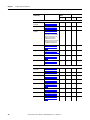
Chapter 4
Configuring the Ultra5000 Drive Introduction. . . . . . . . . . . . . . . . . . . . . . . . . . . . . . . . . . . . . . . . . . . . . . . . . . . . 137
Configuring the Ultra5000 Drive. . . . . . . . . . . . . . . . . . . . . . . . . . . . . . . . .
Configuring Properties for the Ultra5000 Drive . . . . . . . . . . . . . . .
Understanding the Ultra5000 Drive Branch. . . . . . . . . . . . . . . . . . . . . . .
Installing Drivers . . . . . . . . . . . . . . . . . . . . . . . . . . . . . . . . . . . . . . . . . . . .
Drive Report . . . . . . . . . . . . . . . . . . . . . . . . . . . . . . . . . . . . . . . . . . . . . . . .
Understanding the Motion Branch . . . . . . . . . . . . . . . . . . . . . . . . . . . . . . .
Understanding the Jog Window . . . . . . . . . . . . . . . . . . . . . . . . . . . . . . . . . .
Understanding the Move Window . . . . . . . . . . . . . . . . . . . . . . . . . . . . . . .
Understanding the Cam Window . . . . . . . . . . . . . . . . . . . . . . . . . . . . . . . .
Inserting a Cam Table . . . . . . . . . . . . . . . . . . . . . . . . . . . . . . . . . . . . . . .
Importing a Cam Table . . . . . . . . . . . . . . . . . . . . . . . . . . . . . . . . . . . . . .
Importing a CSV File . . . . . . . . . . . . . . . . . . . . . . . . . . . . . . . . . . . . . . . .
Cam Table branch . . . . . . . . . . . . . . . . . . . . . . . . . . . . . . . . . . . . . . . . . . . . . .
Cam Table Editor . . . . . . . . . . . . . . . . . . . . . . . . . . . . . . . . . . . . . . . . . . .
Understanding the Gear Window . . . . . . . . . . . . . . . . . . . . . . . . . . . . . . . .
Understanding the Motor Window. . . . . . . . . . . . . . . . . . . . . . . . . . . . . . .
Understanding the Tuning Window. . . . . . . . . . . . . . . . . . . . . . . . . . . . . .
Autotuning Window . . . . . . . . . . . . . . . . . . . . . . . . . . . . . . . . . . . . . . . .
Understanding the Encoders Window . . . . . . . . . . . . . . . . . . . . . . . . . . . .
Understanding the Digital Inputs Window. . . . . . . . . . . . . . . . . . . . . . . .
Understanding the Digital Outputs Window . . . . . . . . . . . . . . . . . . . . . .
Understanding the Analog Inputs Window . . . . . . . . . . . . . . . . . . . . . . .
Understanding the Analog Outputs Window. . . . . . . . . . . . . . . . . . . . . .
Understanding the Oscilloscope Window . . . . . . . . . . . . . . . . . . . . . . . . .
Channel Setup Window . . . . . . . . . . . . . . . . . . . . . . . . . . . . . . . . . . . . .
Understanding Ultra5000 with DeviceNet . . . . . . . . . . . . . . . . . . . . . . . .
Monitoring Your Ultra5000 Drive . . . . . . . . . . . . . . . . . . . . . . . . . . . . . . .
Ultra5000 Status . . . . . . . . . . . . . . . . . . . . . . . . . . . . . . . . . . . . . . . . . . . . . . . .
Understanding the Programs Branch . . . . . . . . . . . . . . . . . . . . . . . . . . . . .
Understanding the Archives Branch . . . . . . . . . . . . . . . . . . . . . . . . . . . . . .
Understanding the Files Branch . . . . . . . . . . . . . . . . . . . . . . . . . . . . . . . . . .
Understanding the Global Variables Branch . . . . . . . . . . . . . . . . . . . . . . .
Creating a new Global Variable . . . . . . . . . . . . . . . . . . . . . . . . . . . . . . .
Editing an Existing Global Variable . . . . . . . . . . . . . . . . . . . . . . . . . . .
Understanding the Faults Window . . . . . . . . . . . . . . . . . . . . . . . . . . . . . . .
Understanding the Service Information Window . . . . . . . . . . . . . . . . . .
Rockwell Automation Publication 2098-UM001G-EN-P - February 2011
138
139
141
145
145
146
147
149
151
154
154
154
155
155
161
163
168
172
175
180
182
184
186
188
190
193
196
199
205
205
206
206
207
208
210
217
7
Table of Contents
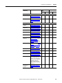
Chapter 5
Configuring the Kinetix 3 Drive
8
Introduction . . . . . . . . . . . . . . . . . . . . . . . . . . . . . . . . . . . . . . . . . . . . . . . . . . . .
Configuring the Kinetix 3 Drive . . . . . . . . . . . . . . . . . . . . . . . . . . . . . . . . . .
Configuring Properties for the Kinetix 3 Drive . . . . . . . . . . . . . . . .
Understanding the Kinetix 3 Drive Branch . . . . . . . . . . . . . . . . . . . . . . . .
Velocity Control Panel Window . . . . . . . . . . . . . . . . . . . . . . . . . . . . . .
Using the Setup Wizard . . . . . . . . . . . . . . . . . . . . . . . . . . . . . . . . . . . . . .
Understanding the Analog Window . . . . . . . . . . . . . . . . . . . . . . . . . . . . . .
Understanding the Preset Window . . . . . . . . . . . . . . . . . . . . . . . . . . . . . . .
Understanding the Follower Window . . . . . . . . . . . . . . . . . . . . . . . . . . . . .
Understanding the Indexing Window . . . . . . . . . . . . . . . . . . . . . . . . . . . . .
Understanding the Homing Window . . . . . . . . . . . . . . . . . . . . . . . . . . . . .
Understanding the Motor Window . . . . . . . . . . . . . . . . . . . . . . . . . . . . . . .
Understanding the Tuning Window . . . . . . . . . . . . . . . . . . . . . . . . . . . . . .
Autotuning Window . . . . . . . . . . . . . . . . . . . . . . . . . . . . . . . . . . . . . . . .
Manual Position Tuning Window . . . . . . . . . . . . . . . . . . . . . . . . . . . .
Manual Velocity Tuning Window . . . . . . . . . . . . . . . . . . . . . . . . . . . .
Understanding the Encoders Window . . . . . . . . . . . . . . . . . . . . . . . . . . . .
Understanding the Digital Inputs Window . . . . . . . . . . . . . . . . . . . . . . . .
Understanding the Digital Outputs Window . . . . . . . . . . . . . . . . . . . . . .
Understanding the Analog Outputs Window . . . . . . . . . . . . . . . . . . . . . .
Understanding the Monitor Window . . . . . . . . . . . . . . . . . . . . . . . . . . . . .
Monitor Setup Window. . . . . . . . . . . . . . . . . . . . . . . . . . . . . . . . . . . . . .
Understanding the Oscilloscope Window . . . . . . . . . . . . . . . . . . . . . . . . .
Channel Setup Window. . . . . . . . . . . . . . . . . . . . . . . . . . . . . . . . . . . . . .
Understanding Kinetix 3 Status Displays . . . . . . . . . . . . . . . . . . . . . . . . . .
Understanding the Faults Window . . . . . . . . . . . . . . . . . . . . . . . . . . . . . . .
Understanding the Fault Detail Window . . . . . . . . . . . . . . . . . . . . . . . . . .
Understanding the Service Information Window . . . . . . . . . . . . . . . . . .
Rockwell Automation Publication 2098-UM001G-EN-P - February 2011
221
222
222
225
234
236
237
239
241
243
246
249
253
258
260
262
265
267
271
274
275
276
278
281
282
287
296
297
Table of Contents
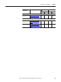
Chapter 6
Creating and Running Programs Introduction. . . . . . . . . . . . . . . . . . . . . . . . . . . . . . . . . . . . . . . . . . . . . . . . . . . . 299
Using a Project Branch . . . . . . . . . . . . . . . . . . . . . . . . . . . . . . . . . . . . . . . . . .
Creating a New Project . . . . . . . . . . . . . . . . . . . . . . . . . . . . . . . . . . . . . .
Configuring a Project . . . . . . . . . . . . . . . . . . . . . . . . . . . . . . . . . . . . . . . .
Executing Project Commands . . . . . . . . . . . . . . . . . . . . . . . . . . . . . . . .
Using Source Files. . . . . . . . . . . . . . . . . . . . . . . . . . . . . . . . . . . . . . . . . . . . . . .
Creating a New Source File . . . . . . . . . . . . . . . . . . . . . . . . . . . . . . . . . .
Renaming a Source File . . . . . . . . . . . . . . . . . . . . . . . . . . . . . . . . . . . . . .
Using Header Files . . . . . . . . . . . . . . . . . . . . . . . . . . . . . . . . . . . . . . . . . . . . . .
Creating a New Header File . . . . . . . . . . . . . . . . . . . . . . . . . . . . . . . . . .
Renaming a Header File. . . . . . . . . . . . . . . . . . . . . . . . . . . . . . . . . . . . . .
Executing Source or Header File Commands . . . . . . . . . . . . . . . . . .
Using the Motion Library Dialog . . . . . . . . . . . . . . . . . . . . . . . . . . . . . . . . .
Using the Text Editor . . . . . . . . . . . . . . . . . . . . . . . . . . . . . . . . . . . . . . . . . . .
Find . . . . . . . . . . . . . . . . . . . . . . . . . . . . . . . . . . . . . . . . . . . . . . . . . . . . . . . .
Find Next. . . . . . . . . . . . . . . . . . . . . . . . . . . . . . . . . . . . . . . . . . . . . . . . . . .
Replace . . . . . . . . . . . . . . . . . . . . . . . . . . . . . . . . . . . . . . . . . . . . . . . . . . . . .
Select All . . . . . . . . . . . . . . . . . . . . . . . . . . . . . . . . . . . . . . . . . . . . . . . . . . .
Go To Corresponding { } ( ) . . . . . . . . . . . . . . . . . . . . . . . . . . . . . . . . . .
Go To Line Number. . . . . . . . . . . . . . . . . . . . . . . . . . . . . . . . . . . . . . . . .
Bookmarks. . . . . . . . . . . . . . . . . . . . . . . . . . . . . . . . . . . . . . . . . . . . . . . . . .
Show Line Numbers . . . . . . . . . . . . . . . . . . . . . . . . . . . . . . . . . . . . . . . . .
Wildcard Search Characters . . . . . . . . . . . . . . . . . . . . . . . . . . . . . . . . . .
Replace . . . . . . . . . . . . . . . . . . . . . . . . . . . . . . . . . . . . . . . . . . . . . . . . . . . . .
Select All . . . . . . . . . . . . . . . . . . . . . . . . . . . . . . . . . . . . . . . . . . . . . . . . . . .
Undo. . . . . . . . . . . . . . . . . . . . . . . . . . . . . . . . . . . . . . . . . . . . . . . . . . . . . . .
Redo . . . . . . . . . . . . . . . . . . . . . . . . . . . . . . . . . . . . . . . . . . . . . . . . . . . . . . .
Using Executable Program Files . . . . . . . . . . . . . . . . . . . . . . . . . . . . . . . . . .
Creating a Program . . . . . . . . . . . . . . . . . . . . . . . . . . . . . . . . . . . . . . . . . .
Configuring a Program. . . . . . . . . . . . . . . . . . . . . . . . . . . . . . . . . . . . . . .
Executable Program File Commands . . . . . . . . . . . . . . . . . . . . . . . . . .
Importing and Exporting Files. . . . . . . . . . . . . . . . . . . . . . . . . . . . . . . . . . . .
Exporting Projects, Header Files and Source Files . . . . . . . . . . . . . .
Importing Projects, Header Files, and Source Files. . . . . . . . . . . . . .
Executing Your Program. . . . . . . . . . . . . . . . . . . . . . . . . . . . . . . . . . . . . . . . .
Run (Program) . . . . . . . . . . . . . . . . . . . . . . . . . . . . . . . . . . . . . . . . . . . . . .
Stop (Program). . . . . . . . . . . . . . . . . . . . . . . . . . . . . . . . . . . . . . . . . . . . . .
Kill (Program) . . . . . . . . . . . . . . . . . . . . . . . . . . . . . . . . . . . . . . . . . . . . . .
Using Direct Commands . . . . . . . . . . . . . . . . . . . . . . . . . . . . . . . . . . . . . . . .
Rockwell Automation Publication 2098-UM001G-EN-P - February 2011
299
299
300
302
303
303
303
305
305
305
306
307
309
309
310
310
311
311
312
312
315
316
316
318
318
319
320
320
320
321
323
323
324
325
325
325
326
327
9
Table of Contents
Chapter 7
Creating Custom Motors
Introduction . . . . . . . . . . . . . . . . . . . . . . . . . . . . . . . . . . . . . . . . . . . . . . . . . . . .
Accessing the Motor Database . . . . . . . . . . . . . . . . . . . . . . . . . . . . . . . . . . . .
Creating Custom Motor Parameter Sets . . . . . . . . . . . . . . . . . . . . . . . . . . .
Motor Database . . . . . . . . . . . . . . . . . . . . . . . . . . . . . . . . . . . . . . . . . . . . . . . . .
Using the Linear Motor Window . . . . . . . . . . . . . . . . . . . . . . . . . . . . . . . . .
Using the Rotary Motor Window. . . . . . . . . . . . . . . . . . . . . . . . . . . . . . . . .
Importing Motors . . . . . . . . . . . . . . . . . . . . . . . . . . . . . . . . . . . . . . . . . . . . . . .
Exporting Motors . . . . . . . . . . . . . . . . . . . . . . . . . . . . . . . . . . . . . . . . . . . . . . .
331
331
332
333
335
337
338
338
Appendix A
Ultraware Software Updates
10
Introduction . . . . . . . . . . . . . . . . . . . . . . . . . . . . . . . . . . . . . . . . . . . . . . . . . . . .
Version 1.80 . . . . . . . . . . . . . . . . . . . . . . . . . . . . . . . . . . . . . . . . . . . . . . . . . . . .
Kinetix 3 Drive-related Enhancements . . . . . . . . . . . . . . . . . . . . . . . .
General Enhancements . . . . . . . . . . . . . . . . . . . . . . . . . . . . . . . . . . . . . . .
Version 1.64 . . . . . . . . . . . . . . . . . . . . . . . . . . . . . . . . . . . . . . . . . . . . . . . . . . . .
Ultra3000 Drive-related Enhancements . . . . . . . . . . . . . . . . . . . . . . .
Version 1.63 . . . . . . . . . . . . . . . . . . . . . . . . . . . . . . . . . . . . . . . . . . . . . . . . . . . .
Ultra3000 Drive-related Enhancements . . . . . . . . . . . . . . . . . . . . . . .
Ultra5000 Drive-related Enhancements . . . . . . . . . . . . . . . . . . . . . . .
Version 1.60 . . . . . . . . . . . . . . . . . . . . . . . . . . . . . . . . . . . . . . . . . . . . . . . . . . . .
Ultra1500 Drive-related Enhancements . . . . . . . . . . . . . . . . . . . . . . .
Ultra3000 Drive-related Enhancements . . . . . . . . . . . . . . . . . . . . . . .
Ultra5000 Drive-related Enhancements . . . . . . . . . . . . . . . . . . . . . . .
General Enhancements . . . . . . . . . . . . . . . . . . . . . . . . . . . . . . . . . . . . . . .
Help File Enhancements . . . . . . . . . . . . . . . . . . . . . . . . . . . . . . . . . . . . .
Version 1.50 . . . . . . . . . . . . . . . . . . . . . . . . . . . . . . . . . . . . . . . . . . . . . . . . . . . .
Ultra3000 Drive-related Enhancements . . . . . . . . . . . . . . . . . . . . . . .
Ultra5000 Drive-related Enhancements . . . . . . . . . . . . . . . . . . . . . . .
General . . . . . . . . . . . . . . . . . . . . . . . . . . . . . . . . . . . . . . . . . . . . . . . . . . . . .
Version 1.40 . . . . . . . . . . . . . . . . . . . . . . . . . . . . . . . . . . . . . . . . . . . . . . . . . . . .
Ultra3000 Drive-related Enhancements . . . . . . . . . . . . . . . . . . . . . . .
Ultra5000 Drive-related Enhancements . . . . . . . . . . . . . . . . . . . . . . .
General Enhancements . . . . . . . . . . . . . . . . . . . . . . . . . . . . . . . . . . . . . .
Version 1.30 . . . . . . . . . . . . . . . . . . . . . . . . . . . . . . . . . . . . . . . . . . . . . . . . . . . .
Ultra3000 Drive-related Enhancements . . . . . . . . . . . . . . . . . . . . . . .
Ultra5000 Drive-related Enhancements . . . . . . . . . . . . . . . . . . . . . . .
General Enhancements . . . . . . . . . . . . . . . . . . . . . . . . . . . . . . . . . . . . . . .
Installation Notes . . . . . . . . . . . . . . . . . . . . . . . . . . . . . . . . . . . . . . . . . . . . . . .
Rockwell Automation Publication 2098-UM001G-EN-P - February 2011
339
339
339
339
339
339
339
339
339
340
340
340
340
340
340
342
342
342
343
343
343
343
344
344
344
345
345
346
Preface
About This Publication
This manual provides detailed installation instructions, defines software interface
features, and programming assistance for Ultraware software.
Who Should Use this
Manual
Use this manual when Ultraware software release 1.8 is used to configure and
operate Ultra1500, Ultra3000, Ultra5000 and Kinetix 3 drives, or when
designing, testing or running ModBus, C language programs, or cam tables on
these drives.
Conventions Used in This
Manual
The conventions listed below are used throughout this manual.
• Bulleted lists such as this one provide information, not procedural steps
• Numbered lists provide sequential steps or hierarchical information
Rockwell Automation Publication 2098-UM001G-EN-P - February 2011
11
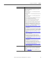
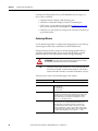
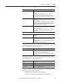
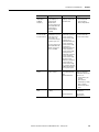
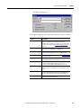
Additional Resources
These documents contain additional information concerning related
Rockwell Automation products.
Resource
Description
Ultra3000 Hardware Installation Manual, publication 2098-IN003
Ultra3000 drive installation and programming procedures.
Ultra3000 SERCOS Integration Manual, publication 2098-IN005
How to configure the Ultra3000 SERCOS interface hardware with
the ControlLogix SERCOS module.
Ultra3000 DSD with DeviceNet Reference Manual, publication 2098-RM001
Object models for Ultra3000 DeviceNet applications.
Ultra5000 Hardware Installation Manual, publication 2098-IN001
Ultra5000 drive installation and programming procedures.
Ultra5000 IPD with DeviceNet Reference Manual, publication 2098-RM002
How to configure and monitor the Ultra5000 drive using the
DeviceNet interface.
Kinetix 3 Component Servo Drive Installation Instructions, publication 2071-IN001
Information on installing your Kinetix 3 drive system.
Kinetix 3 Component Servo Drive Serial Host Command Reference Manual,
publication 2071-RM001
Information on the serial communication commands, both ASCII and
ModBus-RTU, for interfacing a motion controller with the Kinetix 3
drive.
Ultraware Programming Manual, publication 2098-PM001
Information on programming the Ultra5000 using the Ultraware
programming environment. Intended for programmers with a basic
understanding of the C programming language.
Ultraware CD Installation Instructions, publication 2098-IN002
Instructions for installing Ultraware software
System Design for Control of Electrical Noise Reference Manual,
publication GMC-RM001
Information, examples, and techniques designed to minimize
system failures caused by electrical noise.
Kinetix Motion Control Selection Guide, publication GMC-SG001
Specifications, motor/servo-drive system combinations, and
accessories for Kinetix motion control products.
Motion Analyzer CD, download at http://www.ab.com/motion/software/
analyzer_download.html
Drive and motor sizing with application analysis software.
Rockwell Automation Configuration and Selection Tools,
website http://www.rockwellautomation.com/en/e-tools
Online product selection and system configuration tools, including
AutoCAD (DXF) drawings.
Rockwell Automation Product Certification,
website http://www.rockwellautomation.com/products/certification
Website for declarations of conformity (DoC) currently available
from Rockwell Automation.
National Electrical Code, published by the National Fire Protection Association of
Boston, MA
An article on wire sizes and types for grounding electrical
equipment.
Rockwell Automation Industrial Automation Glossary, publication AG-7.1
A glossary of industrial automation terms and abbreviations.
You can view or download publications at http://www.rockwellautomation.com/
literature/. To order paper copies of technical documentation, contact your local
Rockwell Automation distributor or sales representative.
12
Rockwell Automation Publication 2098-UM001G-EN-P - February 2011
Chapter
1
Before You Begin
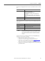
Introduction
Use this chapter to become familiar with Ultraware software components.
This chapter also reviews design and installation requirements for Ultraware
software.
About Ultraware Software
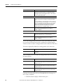
Topic
Page
Introduction
13
About Ultraware Software
13
About Ultraware Software
13
Using Online Help
14
How Ultraware Software Works
14
Understanding the Graphical User Interface
15
Starting Ultraware Software
21
Upgrading Drive Firmware
22
Ultraware software is a Windows 95/98/2000/NT/XP application by Rockwell
Automation that provides a programming environment for the Kinetix 3,
Ultra1500, Ultra3000, and Ultra5000 drives. You can use Ultraware software to
accomplish these tasks.
• Communicate with multiple drives, using the serial port on your computer.
• Adjust the feedback loop gains and parameters of your drive for specific
motors and loads.
• Define the motion capabilities of the drive with the operating modes and
motion functions from compatible drives.
• Configure I/O for the drives.
• Write, load, and execute C language motion programs for Ultra5000
drives.
• Monitor a wide variety of status and motion parameters on the drives.
• Customize the application interface to display only the information you
wish to see.
Rockwell Automation Publication 2098-UM001G-EN-P - February 2011
13
Chapter 1
Before You Begin
Download Ultraware
Software
To communicate and configure your Kinetix 3 drive by using serial
communication from a personal computer, download and install Ultraware
software on your personal computer. To get the latest Ultraware software follow
these steps.
1. Navigate to http://www.ab.com/motion/software/get/
Ultraware_1_80.exe.
2. Click Run.
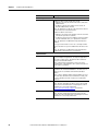
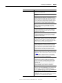
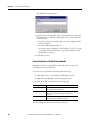
Using Online Help
The following types of online help are available.
To use this
Do this
Description
Help files
Click Contents and Index from
the Help menu. Navigate the
help files using the Table of
Contents, the Index and the
Search tabs.
Descriptions of all on-screen
objects.
Object property configuration
settings.
How to information.
Context Sensitive Help files
Click Help in the active window,
or
Click an on-screen object and
press F1.
For help about the selected
object.
You can also click the Tip of the Day command from the Help menu, which
opens a dialog box that displays helpful hints on using Ultraware software.
How Ultraware Software
Works
Ultraware software is one part of a motion control system. The user commands
the Ultraware software to:
• use a compiler/linker tool to produce executable programs.
• communicate with the drive through a separate Communication library.
• use the Communication library to:
– download program and configuration information,
– execute direct commands, and
– retrieve program, configuration, and status information.
At startup you see several work areas that let you perform tasks. For example, you
can create or edit Ultra5000 programs in a text editor, using the C programming
language.
14
Rockwell Automation Publication 2098-UM001G-EN-P - February 2011
Before You Begin
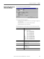
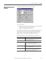
Understanding the
Graphical User Interface
Chapter 1
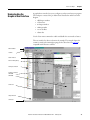
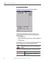
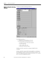
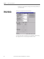
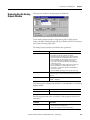
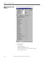
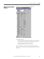
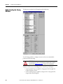
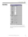
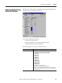
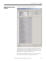
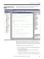
A graphical user interface lets you to configure your drives and run your program.
The workspace consists of the pre-defined areas listed below and shown in the
diagram.
• a Workspace window
• a Client Area
• an Output window
• a Main menubar
• a set of Toolbars
• a Status bar
Use the View menu commands to enable and disable the user interface features.
The user interface for drives is shown in the example. The example depicts the
common control and command groupings for the drives listed on page 13 as
compatible with Ultraware software.
Main menubar
Toolbars
Editor windows
Motion Library dialog
Workspace window
Properties windows
Ultra3000
Ultra5000
Client area
Output window
Status bar
Rockwell Automation Publication 2098-UM001G-EN-P - February 2011
15
Chapter 1
Before You Begin
Workspace Window
The Workspace window is, by default, beneath the menubar and toolbars, and
above the Status Bar. Use the F7 key to return focus to the Workspace window.
The Workspace window has two main branches.
Branch
Description of Display
On-Line Drives branch
All connected online drives and their child objects.
File branch
All configured offline Ultra3000 and Ultra5000 drives, their child
objects and available projects (including all child source, header
and executable files)
Use the Workspace window to navigate to all of the connected online and offline
objects and perform these tasks.
• Create new Drive, Folder, Project, Header, and Source files.
• Cut, Copy, Paste, and Delete Workspace window objects.
• Open the Properties dialog box for Workspace window objects.
• Copy or create cam table files, which you can edit or graphically modify.
• Open the text editor, which you can use to edit header and source files.
• Use the Build command to compile a Project and create an executable
program (.exe) file.
• Copy or Move an executable program (.exe) file from an Ultra5000 drive's
Projects branch to a Programs branch for storage or for execution.
• Copy a configured online drive with all its children from the On-Line
Drives branch, to an offline file, or vice-versa.
• Run an executable program (.exe) file in the Programs branch of an online
Ultra5000 drive.
• Issue direct commands for certain online drive objects.
You can resize and move the Workspace window in several ways.
• In its default state attached to the interface, you can double-click the title
bar to detach the Workspace window from the interface.
• If detached, the Workspace window possesses all of the properties of any
window. It can be resized or moved entirely outside the interface.
• To return the Workspace window to its default position, double-click the
title bar.
To hide the Workspace window, remove the checkmark from the Workspace in
the View menu.
16
Rockwell Automation Publication 2098-UM001G-EN-P - February 2011
Before You Begin
Chapter 1
Output Window
The Output window is, by default, beneath the Workspace window above the
Status Bar. The Output window is visible when the View menu's Output
command is active (denoted by a check mark); it is hidden when the Output
command is not active. The Output window is also visible when you execute the
Program menu’s Build command.
The Output window describes the progress of the current (or most recent) Build
command. If a Build succeeds, the Output window displays the message Build
completed successfully!. If a Build fails, the Output window displays the message
Build failed. along with an fault message describing the cause of the failure.
Ultraware software removes any pre-existing executable program (.exe.) file,
bearing the project name, if a Build fails.
When a Build fails, double-click the Output window fault message with the this
format.
<Filename>:<Line number>:<fault or warning message>
This will open the associated source or header file and position the cursor at the
line referenced by the fault or warning message.
You can resize and move the Output window in several ways.
• In its default state (attached to the interface) you can double-click the title
bar to detach the Output window from the interface.
• Once detached, the Output window possesses all the properties of any
window. It can be resized or moved entirely outside the interface.
• To return the Output window to its default position, double-click the title
bar.
You can copy text in the Output window. However, you cannot type text into the
Output window.
Rockwell Automation Publication 2098-UM001G-EN-P - February 2011
17
Chapter 1
Before You Begin
Client Area
The Client Area is the large gray area beneath the menubar and toolbars and to
the right of the Workspace window.
Use the Client Area to display:
• property windows for objects in the Workspace window, where you can
configure the object’s properties.
• text editor windows for header and source files in the Workspace window,
where you can create or edit these text files.
The Workbook Mode in the View menu displays a tab for each object in the
Client Area. The tab contains the abbreviated name of the related object. Click a
tab to bring the related object to the top of the Client Area.
Unlike windows, the Client Area cannot be directly resized. The size of the
Client Area depends upon the size and location of the surrounding Workspace
and Output windows, the Main menubar, the Status Bar and the several toolbars.
However, you can use the Cascade, Tile Wide, Tile Tall and Arrange Icons
Window menu commands to arrange the display of windows in the client area.
18
Rockwell Automation Publication 2098-UM001G-EN-P - February 2011
Before You Begin
Chapter 1
Main Menubar
The Main menubar is at the top of the interface. Use it to customize the main
window, and to perform essential functions and procedures with respect to
objects in the Main Window.
The main menubar looks like this.
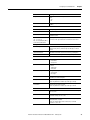
The menu items contain these commands.
Menu Name
Contains these Commands
File
New, Open, Save, Save As, Close, Print, Print Preview, Print Setup, Import,
Export, Upgrade Firmware, Exit
Edit
Undo, Redo, Cut, Copy, Paste, Delete, Find, Go To Corresponding { } ( ),
Go To Line Number, Replace, Select All, Toggle Bookmark, Next Bookmark,
Previous Bookmark, Clear All Bookmarks, Properties
View
Toolbars, Status Bar, Workspace, Output, Workbook Mode, Motion Library
Insert
Ultra3000, Ultra5000, Project, Source File, Header File, Variable, Cam Table
Program
Build, Run, Stop, Kill
Tools
Customize, Rescan, Serial Port, Recover Communications
Commands
Enabled, other direct commands
Window
Close All, Cascade, Tile Wide, Tile Tall, Arrange Icons
Help
Contents and Index, Tip Of The Day, Release Notes, About Ultraware
Rockwell Automation Publication 2098-UM001G-EN-P - February 2011
19
Chapter 1
Before You Begin
Toolbars
Four standard Windows toolbars can be detached from the user interface and
relocated. To return a toolbar to its last docking position, double-click the header
bar.
Toolbar Name
Contains these Commands
File
New, Open, Save, Print, About, Locate
Edit
Cut, Copy, Paste, Erase, Find, Find Next, Undo, Redo, Toggle Bookmark, Next
Bookmark, Previous Bookmark, Clear All Bookmarks
Program
Build, Run, Stop, Kill
Enable
Enable, Disable All
Use the Toolbars command (in the View menu) to open the Toolbars dialog box,
and enable or disable existing toolbars, and create new toolbars.
Use the Customize command (in either the Toolbars dialog box or the Tools
menu) to open the Customize dialog box, where you can:
• add a command icon to a toolbar by dragging it from the Command tab
and dropping it on the desired toolbar.
• delete a command icon from a toolbar by dragging it from a toolbar and
dropping it off the toolbar.
Status Bar
To display the Status bar, use the View menu Status Bar command. The status bar
contains:
• Tooltip help - a description of the menu or button command immediately
beneath the pointer.
• indicators for caps lock (CAP), num lock (NUM) and scroll lock (SCRL).
• row and column reference for the cursor, if a source file or header file has
focus in the Text Editor.
When the status bar is visible, a check mark appears to the left of the Status Bar
command in the View menu.
Motion Library Dialog
The Ultraware Motion Library dialog lets you to quickly find and insert specific
motion library commands and C statements in a motion program.
The Motion Library is displayed when a source or header file is open; and is
hidden when source and header files are closed or not the top view windows. The
Motion Library dialog is docked to the right side of the main window by default.
20
Rockwell Automation Publication 2098-UM001G-EN-P - February 2011
Before You Begin
Starting Ultraware
Software
Chapter 1
When you start the software for the first time, it prompts you to Open Last File,
xxx.udb, Open existing file, or Create new file. After you click the file to open or
create, the software scans the network for online drives.
You may need to configure your PC’s serial port settings (refer to Serial Port
Settings on page 22) and rescan the network (refer to Scanning the Network on
page 21) to verify that the software successfully locates all online network drives.
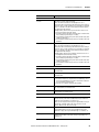
Opening an Ultraware File
The name and location of any open file is stored in memory, when you close your
software. Each time the software opens, it displays a dialog that lets you do one of
these commands.
Select
Description
Open Last File, xxx.udb, and then OK
Opens the most recently used Ultraware file.
Open existing file, and then OK
Open another, existing Ultraware file of your choice.
Create new file, and then OK
Open a new Ultraware file.
Cancel
Open Ultraware without an active file in the Workspace
window.
TIP
A new file is held in temporary storage until saved.
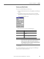
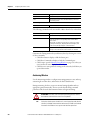
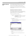
Scanning the Network
When the software opens, it conducts a search of the network for all connected
drives. The Scan For On-Line Drives dialog displays the progress of the online
node scan (0…255), and the specific task the software is currently undertaking
(for example, Scanning Node or Attaching to Node).
Click Stop Scanning to stop the scanning for and attaching to online drives.
The On-Line Drives branch of the Workspace window displays each drive
detected. Because the software does not automatically update the Workspace
window, click Rescan from the Tools menu to display the list of drives that are
currently online.
Rockwell Automation Publication 2098-UM001G-EN-P - February 2011
21
Chapter 1
Before You Begin
Serial Port Settings
After you open the software for the first time, you may change the configuration
of the personal computer’s serial port and baud rate settings. The default settings
are COM1 and 38400. Perform these steps to change the settings.
1. Click Serial Port from the Tools menu.
2. In the PC Communications Setup dialog box, type the appropriate serial
port settings.
IMPORTANT
Ultra5000 drives support only the format 8 data bits, no parity.
Ultra3000 drives do not support the 57600 bps rate.
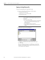
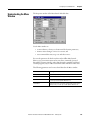
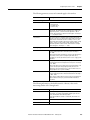
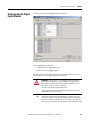
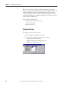
Upgrading Drive Firmware
You can use the software interface to upgrade the firmware for an online drive.
Use the Upgrade Firmware command (in the File menu) to open the Firmware
Upgrade dialog box, where you can perform a flash upgrade to the firmware of a
drive appearing in the On-Line Drives branch of the Workspace window. Before
issuing the Upgrade Firmware command, be sure to first obtain a copy of the new
firmware and any related instructions.
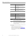
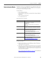
Perform these steps to upgrade firmware in the Firmware Upgrade dialog box.
1. Click the drive for firmware upgrade from the list of On-Line Drives. If a
drive name has been left blank, it is identified as <Unnamed Drive>.
2. Enter the pathname of the new firmware file. Either type in the pathname,
or use the browse button (marked with an ellipsis) to navigate to the new
firmware file. (The new firmware file must have an extension of .hex.)
3. Click Begin Load. The software informs you of firmware upgrade progress
using both a progress bar and status messages.
IMPORTANT
Click Cancel to stop the firmware upgrade. However, If you cancel the
firmware upgrade while it is in progress, the selected drive ceases to be
functional. Thereafter, the selected drive can be used only to complete a
subsequent firmware upgrade.
If drivers are to be installed, also see Installing Drivers on page 145.
22
Rockwell Automation Publication 2098-UM001G-EN-P - February 2011
Chapter
2
Common Commands for Ultra Drive
Configuration
Introduction
This chapter describes show to configure both an online and an offline drive. It
also describes how to copy or move it to an offline Ultraware file, or how to copy
and paste an offline drive (in an Ultraware file) onto an existing online drive,
thereby overwriting the online drive’s settings. It also explains how to use dragand-drop to accomplish the copy and paste process in a single step.
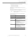
Topic
Page
Introduction
23
Opening Ultraware Software
24
Creating, Opening and Saving Ultraware Files
25
Creating a New Drive
28
Importing and Exporting a Drive
28
Working in the Workspace Window
30
Rockwell Automation Publication 2098-UM001G-EN-P - February 2011
23
Chapter 2
Common Commands for Ultra Drive Configuration
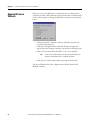
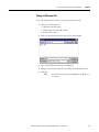
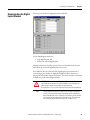
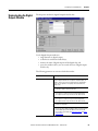
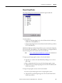
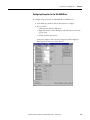
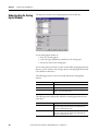
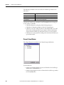
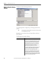
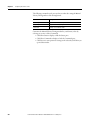
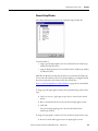
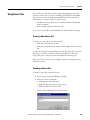
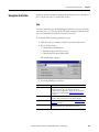
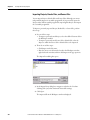
Opening Ultraware
Software
Before you create a new offline drive, you must first create an Ultraware file to
contain the new drive. When Ultraware opens for the first time, a window similar
to the one below appears. Selecting any radio button causes the action described
below.
• Click Open Last File: <filename> and then click OK to open the most
recently used Ultraware file.
• Click Open existing file and then click OK. The Open window will
appear, and you can navigate to and open a previously saved Ultraware file.
• Click Create new file and then click OK to create a new, empty file.
TIP
A new file is stored in temporary storage, and the Workspace icon
displays Unsaved until the file is saved with a filename.
• Click Cancel to exit the window without opening an Ultraware file.
The selected Ultraware file, if any, is displayed in an Off-Line branch of the
Workspace window.
24
Rockwell Automation Publication 2098-UM001G-EN-P - February 2011
Common Commands for Ultra Drive Configuration
Creating, Opening and
Saving Ultraware Files
Chapter 2
An Ultraware file is a container that can hold any number or combination of
offline Ultra3000 and Ultra5000 drives, projects and their children. An
Ultraware file is distinguished by its extension of .udb.
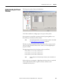
Creating a New Ultraware File
To create a new Ultraware DataBase (.udb) file, perform these steps.
1. Open an Ultraware file using one of these options:
• Click New in the File menu.
• Click the New icon in the File toolbar.
• Press the Ctrl + N keys.
IMPORTANT
If an Ultraware file is already open, a Save Changes window
opens and requires a response before the request to open a new
file executes.
Choose one of these commands.
• Yes - Saves the open file under the filename in the designated
location. Saves the open file under the filename in the
designated location.
• No - Discards the changes to the open file.
• Cancel - Aborts the new Ultraware file, leaving the previous
file open.
2. A new Ultraware file, titled Unsaved, appears in the Workspace under OnLine Drives.
3. The Ultraware file can be populated with drives as described in Creating a
New Drive on page 28, and saved under a name using the directions in
Saving an Ultraware File on page 27.
Rockwell Automation Publication 2098-UM001G-EN-P - February 2011
25
Chapter 2
Common Commands for Ultra Drive Configuration
Opening an Existing Ultraware File
To open an existing Ultraware file, perform these steps.
1. Open an existing Ultraware file using one of these options:
• Click Open in the File menu.
• Click the Open icon in the File toolbar.
• Press the Ctrl + O keys.
Yes
IMPORTANT
If an Ultraware file is already open, a Save Changes window
opens and requires a response before the request to open a new
file executes.
Choose one of these commands.
• Yes - Saves the open file under the filename in the designated
location. Saves the open file under the filename in the
designated location.
• No - Discards the changes to the open file.
• Cancel - Aborts the new Ultraware file, leaving the previous
file open.
2. Perform these steps in the Open dialog box.
a. Navigate to and click the name of the Ultraware file to open.
b. Click Open.
The selected Ultraware file appears in the Workspace window. If the
Workspace window displayed a previously opened Ultraware file, the
selected Ultraware file is displayed.
26
Rockwell Automation Publication 2098-UM001G-EN-P - February 2011
Common Commands for Ultra Drive Configuration
Chapter 2
Saving an Ultraware File
To save all changes made to a drive or a project, perform these steps.
1. Choose one of these options.
• Click Save in the File menu
• Click the Save icon in the File toolbar
• Press the Ctrl + S keys
2. Click Save As in the File menu to open the Save As dialog box.
3. Type or click a file name in the Save As dialog box.
4. Navigate to the location where the new Ultraware file should be stored.
5. Click Save.
TIP
Save As saves the entire Ultraware database (.udb) file to a
new name.
Rockwell Automation Publication 2098-UM001G-EN-P - February 2011
27
Chapter 2
Common Commands for Ultra Drive Configuration
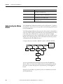
Creating a New Drive
With an Ultraware file open in the Workspace window, you can add a new offline
Ultra3000, Ultra5000, or Kinetix 3 drive.
To add a new drive, perform these steps.
• Click Ultra1500, Ultra3000, Ultra5000, or Kinetix 3 in the Insert Menu.
• Right-click the Ultraware file, and then-click the drive type (Kinetix 3,
Ultra1500, Ultra3000, Ultra5000).
A new drive appears in the Workspace window.
The name of the new drive is Drive or (if Drive already exists) Driven, where n is
the lowest positive integer that creates a unique drive name for the specific drive
model. For example, two 2098-DSD-005 drives may be named Drive and Drive1,
and two 2098-DSD-005X drives may also be named Drive and Drive 1.
Importing and Exporting a
Drive
You can import an existing, previously configured drive to an Ultraware file using
the File menu’s Import command.
Only drives that have been previously exported, using the File menu’s Export
command, can be imported. Exporting a drive saves it as an User data eXchange
File with a .uxf extension.
Exporting a Drive
To Export a drive, perform these steps.
1. Click a drive branch.
2. Do one of these actions to open the Export To dialog box.
• Click Export in the File menu.
• Right-click the drive branch, and click Export in the menu.
3. Type or click a name for the drive in the Export To dialog box.
4. Navigate to a location where the file should be exported.
5. Click Save.
The exported file is saved as an User data eXchange File (with an .uxf extension).
28
Rockwell Automation Publication 2098-UM001G-EN-P - February 2011
Common Commands for Ultra Drive Configuration
Chapter 2
Importing a Drive
To Import a previously exported drive, performs these steps.
1. Click the offline Ultraware file.
2. Do one of these actions to open the The Import From window.
• Click Import in the File menu.
• Right-click the Ultraware file, and then click Import from the pop-up
menu.
3. In the Import From window, navigate to and click the User data eXchange
File (.uxf ) that contains the desired drive settings.
4. Click Open to display the imported drive in the offline Ultraware file.
Rockwell Automation Publication 2098-UM001G-EN-P - February 2011
29
Chapter 2
Common Commands for Ultra Drive Configuration
Working in the Workspace
Window
You can use the Edit menu commands to Cut, Copy, Paste and Delete/Erase
items in the Workspace window. You can also use a Drag and Drop function in
place of Cut and Paste.
Cut
The Cut command removes selected items from the Workspace window. Any
item cut from the Workspace window replaces any other item previously cut (or
copied) and stored on the clipboard.
These Workspace window items cannot be cut.
• an On-Line Drives branch
• a drive in the On-Line Drives branch
• an Ultraware file
• any child branch of a drive
• a program (with an .exe extension) for a project in an offline Ultraware file
To Cut an item from the Workspace window, perform these steps.
1. Click a Workspace window item (other than one of those listed above).
2. Do one of these actions.
• Click Cut in the Edit menu.
• Click Cut from the pop-up menu.
• Simultaneously press the Ctrl + X keys.
• Click the Cut icon in the Edit toolbar.
3. A message box asks you if you wish to continue. Click OK to cut or
Cancel.
30
Rockwell Automation Publication 2098-UM001G-EN-P - February 2011
Common Commands for Ultra Drive Configuration
Chapter 2
Copy
The Copy command copies selected items from the Workspace window. Any
branch or item copied in the Workspace window replaces any other branch or
item previously copied (or cut) and stored in the clipboard.
The following Workspace window items cannot be copied:
• An Ultraware file
• Child branches of a drive.
To copy an item in the Workspace window, perform these steps.
1. Click a Workspace window item (other than one of those listed above).
2. Do one of these actions.
• Click Copy in the Edit menu.
• Right-click on a drive in the Workspace window, then click Copy from
the pop-up menu.
• Simultaneously press the Ctrl + C keys.
• Click the Copy icon in the Edit toolbar.
Paste
The Paste command inserts a previously copied or cut Workspace window item
or branch into the selected location of the Workspace window.
When pasting into the Workspace window, three results can occur:
• If the selected Workspace window item is of the same type as the item to be
pasted, the pasted item replaces the selected item.
• If the selected Workspace window item is a parent branch that must always
have one child of the same type as the item to be pasted, the pasted item
replaces the selected branch's child of the same type.
• If the selected Workspace window branch can have multiple child branches
of the same type as the item to be pasted, the pasted item:
– replaces a child branch with the same name as the pasted item, or
– is added as an additional child branch, if no other child branch shares
the pasted item's name.
Any Workspace window item can be selected to receive a pasted item, except
these items:
• a source (.c) file
• a header (.h) file
• child branches of an Ultra3000 drive.
• some child branches of an Ultra5000 drive
Rockwell Automation Publication 2098-UM001G-EN-P - February 2011
31
Chapter 2
Common Commands for Ultra Drive Configuration
To paste an item in the Workspace window, perform these steps.
1. Click a Workspace window branch in which to paste the item.
IMPORTANT
The Workspace window branch selected can not be any of these
branch types.
•
•
•
•
•
an on-line drive
a child project in the archives
a source (.c) file
a header (.h) file
a child or the children of an Ultra3000 drive
2. Do one of these actions.
• Click Paste in the Edit menu.
• Click on a branch drive in the Workspace window, then right-click
Paste from the pop-up menu.
• Click Paste from the pop-up menu.
• Simultaneously press the Ctrl + V keys.
• Click the Paste icon in the Edit toolbar.
If you are pasting an item into the Workspace window that replaces
another item of the same name, a message box asks if you wish to continue.
3. Click OK to paste, or Cancel to quit.
Delete
The Delete command removes selected branches or items from the Workspace
window. The deleted item is permanently destroyed. The Delete command
cannot be reversed by an Undo command.
These Workspace window items cannot be deleted.
• an On-Line Drives branch
• a drive in the On-Line Drives branch
• an Ultraware file
• an immediate child item branching directly from a drive
• an executable program child (with an .exe extension) of an offline project
To delete an item from the Workspace window, perform these steps.
1. Click a Workspace window item (other than one of those listed above).
2. Do one of these commands.
• Click Delete in the Edit menu.
• Click Delete in the pop-up.
32
Rockwell Automation Publication 2098-UM001G-EN-P - February 2011
Common Commands for Ultra Drive Configuration
Chapter 2
• Click the Erase icon in the Edit toolbar.
3. Click OK to delete or Cancel in the message box that appears.
Drag and Drop
You can use the drag-and-drop method to copy and move a Workspace window
branch or item to other locations within the Workspace window. The drag-anddrop method combines the Cut, Copy and Paste commands, as follows:
• the drag-and-drop method copies a Workspace window branch or item
that can be both copied using the Copy command, and pasted using the
Paste command.
• the drag-and-drop method moves a Workspace window branch or item
that can be both cut using the Cut command, and pasted using the Paste
command.
To use the drag-and-drop method to copy a Workspace window branch or item:
1. Place the cursor arrow on a Workspace window branch or item that can be
copied and hold down the left mouse button.
2. Drag the selected Workspace window branch or item to the desired
destination. One of two things happens:
• If the item can be copied, the pointer continues to appear as an arrow
and a + (plus) sign appears to the right of the arrow (for as long as you
continue drag the item over a place in the Workspace window where it
may be dropped).
• If the item cannot be copied, or if you are dragging the item over a part
of the Workspace window where it may not be dropped, the arrow is
replaced by a circle with a line through it.
3. Release the mouse button when you arrive at the Workspace window
location where you want to copy the Workspace window branch or item.
The result is the same as if you had Copied then Pasted it to this location.
To use the drag-and-drop method to move a Workspace window or item:
1. Place the cursor arrow on a Workspace window or item that can be cut and
hold down both the left mouse button and the Ctrl key.
2. Drag the selected Workspace window or item to the desired destination.
One of two things occurs:
• If the item can be cut, the pointer continues to appear as an arrow (for
as long as you continue drag the item over a place in the Workspace
window where it may be dropped).
• If the item cannot be cut, or if you are dragging the item over a part of
the Workspace window where it may not be dropped, the arrow is
replaced by a circle with a line through it.
Rockwell Automation Publication 2098-UM001G-EN-P - February 2011
33
Chapter 2
Common Commands for Ultra Drive Configuration
3. When you arrive at the Workspace window location where you want to
move the item, release both the mouse button and the Ctrl key. The result
is the same as if you had Cut then Pasted it to this location.
34
Rockwell Automation Publication 2098-UM001G-EN-P - February 2011
Chapter
3
Configuring the Ultra3000 Drive
Introduction
This chapter describes how to configure your Ultra3000 drive to an operational
mode.
Also described are these Ultra3000 drive interface options:
• homing
• oscilloscope
• drive tuning
• drive monitoring
• motor and encoder diagnostic routines
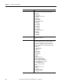
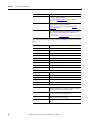
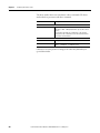
Topic
Page
Introduction
37
Configuring the Ultra3000 Drive
38
Understanding the Ultra3000 Drive Branch
41
Understanding the Analog Window
59
Understanding the Preset Window
62
Understanding the Follower Window
64
Understanding the Indexing Window
66
Understanding the Homing Window
70
Understanding the Motor Window
73
Understanding the Tuning Window
77
Understanding the Encoders Window
86
Understanding the Digital Inputs Window
95
Understanding the Digital Outputs Window
99
Understanding the Analog Outputs Window
103
Understanding the Monitor
105
Understanding the Oscilloscope Window
108
Understanding Ultra3000 with DeviceNet
112
Understanding Ultra3000 Status
118
Understanding the Faults Window
126
Understanding the Service Information Window
135
Rockwell Automation Publication 2098-UM001G-EN-P - February 2011
37
Chapter 3
Configuring the Ultra3000 Drive
Configuring the Ultra3000
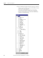
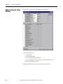
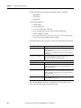
Drive
Each Ultra3000 drive in the Workspace window has these child branches or
windows:
• Operation Modes
– Analog
– Preset
– Follower
– Indexing
– Homing
•
•
•
•
•
•
•
•
•
•
•
Indexing and Homing operation modes are available only for drive types
whose catalog numbers end in X (for example, 2098-DSD-005X).
Motor
Tuning
Encoders
Digital Inputs
Digital Outputs
Analog Outputs
Monitor
Oscilloscope
Faults
DeviceNet
Service Information
Except for the Monitor windows, all of a drive’s child branches can and must be
configured in a Properties window.
38
Rockwell Automation Publication 2098-UM001G-EN-P - February 2011
Configuring the Ultra3000 Drive
Chapter 3
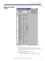
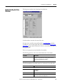
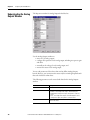
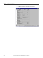
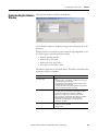
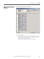
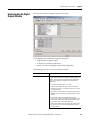
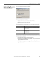
Configuring Properties for the Ultra3000 Drive
To configure the properties for an Ultra3000 drive or one of its child branches,
perform these steps.
1. In the Workspace window, click the drive branch to configure.
2. Do one of these:
• Click Properties from the Edit menu.
• Right-click the drive in the Workspace, and click Export from the popup menu.
• Double-click the drive branch.
TIP
If the drive is a SERCOS drive, only those parameters, status and
direct commands appropriate for a SERCOS drive are displayed.
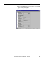
A Properties window, such as the Drive Properties window displayed
below, appears for the selected drive branch.
Rockwell Automation Publication 2098-UM001G-EN-P - February 2011
39
Chapter 3
Configuring the Ultra3000 Drive
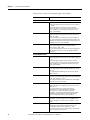
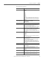
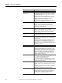
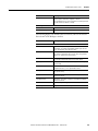
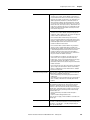
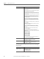
3. To configure properties for the selected drive branch, use the features of
the Properties window as follows.
Section
Description
Parameters
Located in the upper left part of the Properties window. Type or
click settings in the parameter fields to configure the drive branch.
Commands
Located in the upper right part of the Properties window. Click any
button to issue the associated command. Click Show Commands,
below, to display command buttons. Not every drive branch has
associated commands.
Status
Located beneath the Parameters and Commands sections. By
default, these fields display the online status of the selected drive
branch. Click Setup to open a window where you can customize the
status to be displayed. Status fields are read-only. Click Show
Status to display the status section.
Note: Status values for offline drives may not be meaningful.
Show Status
Displays status for the drive branch.
Show Commands
Displays commands for the drive branch. Commands can be
executed only for online drives. This selection is dimmed if no
commands are associated with the selected drive branch.
Setup
Opens the Monitor Setup window, where you can customize the
status display.
Refer to Understanding the Monitor on page 105 for more
information about using the Monitor window.
Revert
Returns parameter settings to the values they had when you first
opened this window.
Close
Closes the window.
Help
Displays online help for this window.
The remainder of this chapter describes the process of entering and editing drive
configuration settings, the status are displayed by default for each drive branch
when the drive is online, and the commands available to a user for each drive
branch when the drive is online.
40
Rockwell Automation Publication 2098-UM001G-EN-P - February 2011
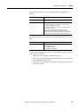
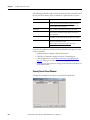
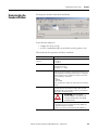
Configuring the Ultra3000 Drive
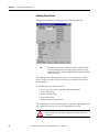
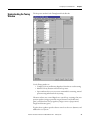
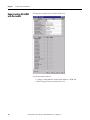
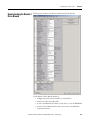
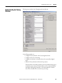
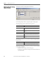
Understanding the
Ultra3000 Drive Branch
Chapter 3
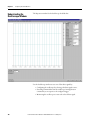
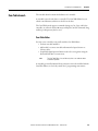
The Properties window for the Ultra3000 Drive branch looks like this.
Rockwell Automation Publication 2098-UM001G-EN-P - February 2011
41
Chapter 3
Configuring the Ultra3000 Drive
Use this Ultra3000 window to:
• configure the parameters for an offline or an online drive
• monitor the status of an online drive
• execute commands that clear faults, reset the drive or reset the EEPROM
• open the Control Panel windows, where you can issue commands that
control drive motion
If the drive is a SERCOS drive, with its SERCOS interface active, the drive is
displayed with a small “S” next to the drive icon. The software displays a custom
workspace tree and property windows, limiting the display appropriately for a
SERCOS drive.
You can edit parameters for both an online and an offline drive. However, you
can monitor status and execute direct commands (executed through the
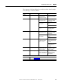
Ultraware interface) only for an Ultra3000 drive in the On-Line Drives branch.
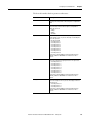
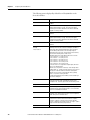
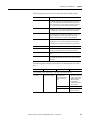
The following parameters apply to the Ultra3000 Drive window.
Parameter
Description
Name
The name of the drive, up to 32 characters long.
Note: The drive name is displayed in the title bar of the windows
relating to this drive.
Auto Motor Iden
Select:
• Enabled: Causes the drive to read motor parameters from an
intelligent encoder, or
• Disabled: Causes the drive to read motor parameters from a
Motor Model selected, below.
Motor Model
The model of the motor to be controlled by the drive. Selecting a
motor model from the drop-down list sets its parameters in the
Motor window.
Note: For an online drive, you must disable the drive before you
can edit its Motor Model parameter.
Note: Ultraware software ships with a utility that lets you create
custom motor configurations. Use that utility to add customized
motor selections to the Motor Model list.
Motor Forward Dir
Click either:
• Normal: a positive direction move increases the encoder count.
• Reverse: a positive direction move decreases the encoder
count.
Displayed Units
Click a unit of measure for position, velocity, and acceleration
displays:
Metric:
• units for rotary motors are: counts (position), rpm (velocity), rpm
per second2 (acceleration);
• units for linear motors are: meters (position), meter per second
(velocity), and meter per second2 (acceleration).
English:
• units for rotary motors are: counts (position), rpm (velocity), rpm
per second2 (acceleration);
• units for linear motors are: inches (position), inches per second
(velocity), and inches per second2 (acceleration).,
User: displays measurements in terms defined by the user in the
Units section, below.
Operation Modes
42
Rockwell Automation Publication 2098-UM001G-EN-P - February 2011
Configuring the Ultra3000 Drive
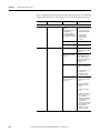
Chapter 3
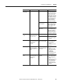
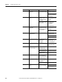
Parameter
Description
Operation Mode
The drive's command source.
Note: An online drive must be disabled before you can edit its
Operation Mode parameter.
Selections include:
• Analog Current Input: a +/- 10 volt analog input provides the
current command.
• Analog Position: a +/- 10 volt analog input provides the position
command.
• Analog Velocity Input: a +/- 10 volt analog input provides the
velocity command.
• Follower: Auxiliary Encoder: a quadrature encoder provides a
position command signal input to the drive.
• Follower: Step/Direction Input: Step and Direction inputs
provide a position command signal input to the drive.
• Follower: Step Up/Step Down Input: Step Up and Step Down
inputs provide a position command signal input to the drive.
• Indexing: (only for Indexing drives) Up to 64 indexes can be
configured in the Indexing window. The combination of Preset
Select Lines 0, 1, 2, 3, 4 and 5, in the Digital Inputs window,
determines the Index (0 – 63) that is selected.
Refer to Understanding the Digital Inputs Window on page 95
for more information about how to assign a Preset Select Line
to a Digital Input.
• Preset Current: a preset Current provides the current command.
Up to 8 Preset Current values can be set in the Preset window.
The combination of Preset Select Lines 0, 1 and 2 in the Digital
Inputs window, determines the Preset Current (0 – 7) that is
selected.
Refer to Understanding the Digital Inputs Window on page 95
for more information about how to assign Preset Select Line
functions to a Digital Input.
• Preset Position: a preset Position provides the position
command. Up to 8 Preset Position values can be set in the
Preset window. The combination of Preset Select Lines 0, 1 and
2 in the Digital Inputs window, determines the Preset Position
(0 – 7) that is selected.
Refer to Understanding the Digital Inputs Window on page 95
for more information about how to assign a Preset Select Line
to a Digital Input.
• Preset Velocity: a Preset Velocity provides the velocity
command. Up to 8 Preset Velocity values can be set in the
Preset window. The combination of Preset Select Lines 0, 1 and
2 in the Digital Inputs window, determines the Preset Velocity
(0 – 7) that is used for the velocity command.
Refer to Understanding the Digital Inputs Window on page 95
for more information about how to assign Preset Select Line
functions to a Digital Input.
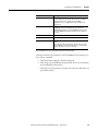
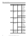
Operation Mode Override
The connected drive's command source that is used when the
Operation Mode Override input is active. The Operation Mode
Override input is assigned to a digital input in the Digital Inputs
window.
Note: See Operation Mode, above, for an explanation of the
available selections.
Rockwell Automation Publication 2098-UM001G-EN-P - February 2011
43
Chapter 3
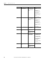
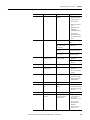
Configuring the Ultra3000 Drive
Parameter
Description
Machine Cycle
Enable or disable a Single-Turn Absolute encoder.
• Enabled: to cause the SRS encoder to be used as an absolute
feedback device
• Disabled: to cause the SRS encoder not to be used as an
absolute feedback device. (Default)
Note: This parameter is visible only if the offline motor selection
or online motor has an SRS/SRM encoder.
Enable or disable Position Rollover:
• Enabled: to cause the position variable to rollover to zero when
it exceeds the specified size. (Default)
• Disabled: to cause the position variable to rollover only when it
exceeds 2147483647 counts, or its equivalent in other units.
Note: This parameter is disabled when Single-Turn Absolute is
enabled.
Size: Type a rollover value in counts. This is an integer at which
the next increment of a position variable will be the value of zero
(0).
Note: This parameter is disabled when Single-Turn Absolute is
enabled, and is automatically set to one revolution.
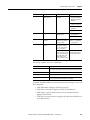
Communications
44
Drive Address
The drive's communication port address - an integer from 0 to 255
- used in multiple axis applications. For single axis applications,
this value is usually set to 0. The drive must be reset before it
recognizes an edited drive address.
Note: Communication port parameters can be set in the PC
Communications Setup dialog box, that is opened using the Tools
menu Serial Port command.
Broadcast Address
The address used by a host PC or PLC to issue a single broadcast
command to all connected Ultra3000 drives. The drive does not
send a response to commands received with the broadcast
address.
Note: If a drive's Broadcast Address and Drive Address are set to
the same value, that drive treats all commands as normal, pointto-point commands, and sends a response to all commands it
processes.
Baud Rate
Baud rate setting for the drive.
Note: The drive's Baud Rate must be the same as the PC's Baud
Rate (set in the PC Communications Setup dialog box) if the PC
and drive are to successfully communicate.
Refer to Serial Port Settings on page 22 for restrictions.
Frame Format
Specify the drive's communication port packet framing format.
Note: The drive's Frame Format must be the same as the PC's
Format (set in the PC Communications Setup dialog box) if the PC
and drive are to successfully communicate.
Rockwell Automation Publication 2098-UM001G-EN-P - February 2011
Configuring the Ultra3000 Drive
Parameter
Chapter 3
Description
Current Limits
Positive
The drive's positive current limit value.
Note: The value entered here is divided by the lesser of
intermittent drive current rating and intermittent current rating of
the motor, and is stored on the drive as a percentage. If a different
motor is selected for the drive, with a different current capacity,
this parameter value changes.
During runtime, the drive limits positive current to the lesser of:
• the Positive Current Limit (this value),
• the analog current limit Input (an analog input of the drive that
limits current proportionately to its value),
• the Intermittent Current rating of the drive (a fixed value, hardcoded into the drive), or
• the Intermittent Current rating of the motor (stored in the motor
database).
Negative
The drive's negative current limit runtime value.
Note: The value entered here is divided by the lesser of
intermittent drive current rating and intermittent current rating of
the motor, and is stored on the drive as a percentage. If a different
motor is selected for the drive, with a different current capacity,
this parameter value changes.
During runtime, the drive limits negative current to the lesser of:
• the Negative Current Limit (this value),
• the analog current limit Input (an analog input of the drive that
limits current proportionately to its value),
• the Intermittent Current rating of the drive (a fixed value, hardcoded into the drive), or
• the Intermittent Current rating of the motor (stored in the motor
database).
Position Limits
Positive Decel Distance
The stopping distance used when the drive encounters a positive
overtravel limit.
Negative Decel Distance
The stopping distance used when the drive encounters a negative
overtravel limit.
Enable Soft Limits
Select:
• On: Causes the drive to compare the motor feedback position to
the Positive and Negative Soft Limits to determine if the drive
has exceeded an overtravel limit.
• Off: Turns off software overtravel limit checking.
Positive Soft Limit
If the motor feedback position is greater than this value, the drive
has exceeded the soft overtravel limit.
Negative Soft Limit
If the motor feedback position is less than this value, the drive has
exceeded the soft overtravel limit.
Speed Functions
Zero Speed
This value creates a plus or minus (+/-) range, or window, around
the zero velocity. If the motor feedback velocity falls within this
range, the Zero Speed flag is (or remains) set.
Note: You can assign the Zero Speed, In Speed Window or Up To
Speed flags to digital outputs and control execution of your
process based on the state of these flags.
In Speed Window
This value creates a plus or minus (+/-) range, or window, around
the programmed velocity. If the motor feedback velocity falls
within this range, the In Speed Window flag is (or remains) set.
Up to Speed
This value sets a velocity level. If the motor feedback velocity is
greater than or equal to this value, the Up To Speed flag is (or
remains) set.
Rockwell Automation Publication 2098-UM001G-EN-P - February 2011
45
Chapter 3
Configuring the Ultra3000 Drive
Parameter
Description
Position Functions
46
In Position Size
The maximum amount of position error that permits the In Position
and the In Position Window flags to be (or remain) set.
In Position Time
The minimum length of time the position error must be less than
the In Position Size value, for the In Position and the In Position
Window flags to be (or remain) set.
Posn Compare 1 Type
Specify the type of comparison that will determine if the Posn
Compare 1 flag should be set. Either:
• Greater Than: the flag will be set if the motor feedback position
is greater than the Posn Compare 1 value.
• Less Than: the flag will be set if the motor feedback position is
less than the Posn Compare 1 value.
• Within Window: the flag will be set if the motor feedback
position is greater than Posn Compare 1 Min and less than
Posn Compare 1 Max.
• Outside Window: the flag will be set if the motor feedback
position is less than Posn Compare 1 Min or more than Posn
Compare 1 Max.
Note: This parameter is supported in firmware revision 1.29 and
higher.
Posn Compare 1
Enter the position, in counts, that is compared to the motor
feedback position to determine if the Posn Compare 1 flag should
be set.
Posn Compare 1 Min
Enter the minimum position, in counts, that will be compared to
the motor feedback position to determine if the Posn Compare 1
flag should be set.
Note: Displayed if Posn Compare 1 Type is set to Within Window
or Outside Window.
Posn Compare 1 Max
Enter the maximum position, in counts, that will be compared to
the motor feedback position to determine if the Posn Compare 1
flag should be set.
Note: Displayed if Posn Compare 1 Type is set to Within Window
or Outside Window.
Posn Compare 1 Polarity
The type of comparison that determines if the Posn Compare 1
flag should be set. Either:
• Greater Than: the flag is set if the motor feedback position is
greater than the Posn Compare 2 value.
• Less Than: the flag is set if the motor feedback position is less
than the Posn Compare 2 value.
Note: Replaced with Posn Compare 1 Type starting with firmware
revision 1.29.
Posn Compare 2 Type
The type of comparison that will determine if the Posn Compare 2
flag should be set. Either:
• Greater Than: the flag will be set if the motor feedback position
is greater than the Posn Compare 2 value.
• Less Than: the flag will be set if the motor feedback position is
less than the Posn Compare 2 value.
• Within Window: the flag will be set if the motor feedback
position is greater than Posn Compare 2 Min and less than
Posn Compare 2 Max.
• Outside Window: the flag will be set if the motor feedback
position is less than Posn Compare 2 Min or more than Posn
Compare 2 Max.
Note: This parameter is supported in firmware revision 1.29 and
higher.
Posn Compare 2
Enter the position, in counts, that is compared to the motor
feedback position to determine if the Posn Compare 2 flag should
be set.
Rockwell Automation Publication 2098-UM001G-EN-P - February 2011
Configuring the Ultra3000 Drive
Chapter 3
Parameter
Description
Posn Compare 2 Min
Enter the minimum position, in counts, that will be compared to
the motor feedback position to determine if the Posn Compare 2
flag should be set.
Note: Displayed if Posn Compare 2 Type is set to Within Window
or Outside Window.
Posn Compare 2 Max
Enter the maximum position, in counts, that will be compared to
the motor feedback position to determine if the Posn Compare 2
flag should be set.
Note: Displayed if Posn Compare 2 Type is set to Within Window
or Outside Window.
Posn Compare 2 Polarity
Specify the type of comparison that determines if the Posn
Compare 2 flag should be set. Either:
• Greater Than: the flag is set if the motor feedback position is
greater than the Posn Compare 2 value.
• Less Than: the flag is set if the motor feedback position is less
than the Posn Compare 2 value.
Note: Replaced with Posn Compare 1 Type starting with firmware
revision 1.29.
Display Precision
Velocity Precision
The number of characters displayed to the right of the decimal
point for velocity values.
Position Precision
The number of characters displayed to the right of the decimal
point for position values.
Acceleration Precision
The number of characters displayed to the right of the decimal
point for acceleration values.
Current Precision
The number of characters displayed to the right of the decimal
point for current values.
Motor Encoder Units
Velocity Label
When User is selected for Displayed Units, this is the user-defined
label for velocity values relating to the motor encoder. Limited to
16 characters in length.
Velocity Scale
When User is selected for Displayed Units, this is the user-defined
conversion factor used to convert velocity values, relating to the
motor encoder, into user units. In counts per second per user unit.
Position Label
When User is selected for Displayed Units, this is the user-defined
label for position values relating to the motor encoder. Limited to
16 characters in length.
Position Scale
When User is selected for Displayed Units, this is the user-defined
conversion factor used to convert position values, relating to the
motor encoder, into user units. In counts per user unit.
Acceleration Label
When User is selected for Displayed Units, this is the user-defined
label for acceleration values relating to the motor encoder. Limited
to 16 characters in length.
Acceleration Scale
When User is selected for Displayed Units, this is the user-defined
conversion factor used to convert acceleration values, relating to
the motor encoder, into user units. In counts per second squared
per user unit.
Rockwell Automation Publication 2098-UM001G-EN-P - February 2011
47
Chapter 3
Configuring the Ultra3000 Drive
Parameter
Description
Auxiliary Encoder Units
Velocity Label
When User is selected for Displayed Units, this is the user-defined
label for velocity values relating to the auxiliary encoder. Limited
to 16 characters in length.
Velocity Scale
When User is selected for Displayed Units, this is the user-defined
conversion factor used to convert velocity values, relating to the
auxiliary encoder, into user units. In counts per second per user
unit.
Position Label
When User is selected for Displayed Units, this is the user-defined
label for position values relating to the auxiliary encoder. Limited
to 16 characters in length.
Position Scale
When User is selected for Displayed Units, this is the user-defined
conversion factor used to convert position values, relating to the
auxiliary encoder, into user units. In Counts per user unit.
Acceleration Label
When User is selected for Displayed Units, this is the user-defined
label for acceleration values relating to the auxiliary encoder.
Limited to 16 characters in length.
Acceleration Scale
When User is selected for Displayed Units, this is the user-defined
conversion factor used to convert acceleration values, relating to
the auxiliary encoder, into user units. In counts per second
squared per user unit.
The following status is displayed by default for an Ultra3000 drive in the OnLine Drives branch of the Workspace window.
Status
Description
Note: All ON status have a value of 1; all OFF status have a value of 0.
48
Drive Enabled
ON indicates the power stage of the drive is enabled. As a
precondition, all software and hardware enable inputs must be
active, and the drive cannot have any faults.
In Position
ON indicates position error has been less than the In Position Size
setting for longer than the In Position Time setting, and the speed is
less than the Zero Speed setting.
In Position Window
ON indicates position error has been less than the In Position Size
setting for longer than the In Position Time setting.
Up To Speed
ON indicates motor velocity feedback is greater than the Up To
Speed setting.
In Speed Window
ON indicates motor velocity feedback falls within the range of
programmed velocity +/- the Speed Window value.
Zero Speed
ON indicates the motor velocity feedback value is less than the
Zero Speed setting.
Pos Current Limit
ON indicates the current of the drive is limited by the Positive
Current Limit, above.
Neg Current Limit
ON indicates the current of the drive is limited by the negative
Current Limit, above.
Bus Power
ON indicates power is applied to the DC Bus.
Bus Voltage
The present measure of Bus voltage.
Rockwell Automation Publication 2098-UM001G-EN-P - February 2011
Configuring the Ultra3000 Drive
Chapter 3
The following commands can be executed for an Ultra3000 Drive window that is
in the On-Line Drives branch. These commands are explained in these sections.
Command
Description
Velocity Control Panel
Opens the Velocity Control Panel window.
Refer to Velocity Control Panel Window on page 50 for more
information about how to set a drive's velocity command and
monitor its motor velocity or current.
Current Control Panel
Opens the Current Control Panel window.
Refer to Current Control Panel Window on page 52 for more
information about how to set a drive's current command and
monitor its motor velocity or current.
Indexing Control Panel
Opens the Indexing Control Panel window. (Only for Indexing
drives.)
Refer to Indexing Control Panel on page 54 for more information
about how to set one of sixty-four possible indexes, monitor the
status of the selected index, and send direct commands to the
selected drive.
Clear Faults
Attempts to clear all drive faults.
Reset Drive
Resets, or reboots, the hardware and firmware for a drive.
Reset EEPROM to Factory
Setting
Resets a drive's parameters by reinitializing them to factory default
settings. Stored faults and the Time in Service clock remain
unchanged
Customize the window for your Ultra3000 Drive branch by selecting one or
more of these commands:
• Click Show Status to display or hide the Status pane.
• Click Show Commands to display or hide the Commands pane.
• Click Setup to open the Monitor Setup window shown on page 105,
where you can customize the status display for this window.
• Click Revert to return parameter settings to the values they held when you
opened this window.
Rockwell Automation Publication 2098-UM001G-EN-P - February 2011
49
Chapter 3
Configuring the Ultra3000 Drive
Velocity Control Panel Window
The Properties window for the Velocity Control Panel looks like this.
Use the Velocity Control Panel window to directly set the drive's velocity in a
temporary velocity mode.
Opening the Velocity Control Panel will stop any motion commands originating
from the drive's normal operation mode, set in the Kinetix 3 Drive window.
ATTENTION: The Velocity Control Panel commands override the normal
operation mode. The motor will move in response to Velocity Control
Panel commands!
The Jog Forward and Jog Reverse commands of the Velocity Control Panel
are not changed by the Command Polarity selection in the Kinetix 3 Drive
Window. They always behave as though the Command Polarity were set to
Normal.
The Velocity Control Panel has these parameters, status, and direct commands.
50
Parameter
Description
Velocity Command
The speed at which the motor will turn when the Jog Forward or
Jog Reverse command executes, provided that the drive is online
and enabled.
The range is 0…6000 rpm for rotary motors (0…6000 millimeters
per second for linear motors). The default is 50.
Acceleration
Displays the maximum rate of acceleration (or deceleration) the
drive uses to ramp up (or down) to the commanded velocity when
velocity changes.
Rockwell Automation Publication 2098-UM001G-EN-P - February 2011
Configuring the Ultra3000 Drive
Chapter 3
The following statuses can be displayed from the Velocity Control Panel window
of an online drive.
Status
Description
Drive Enabled
ON indicates that the power stage of the drive is enabled.
For the power stage to be enabled:
• the drive cannot have any faults, and
• any digital inputs configured as a Drive Enable must be active,
and
• the drive must be set to Enabled, in the Commands menu.
Note: The Drive Enabled status has a value of 1 when ON, and 0
when OFF
Velocity – Motor Feedback
The actual motor velocity.
Current – Motor Feedback
The actual motor current.
TIP
The drive will ramp up, or ramp down, to the commanded velocity at the
rate of acceleration set in the Acceleration Limits in the Kinetix 3 Drive
window.
Command
Description
Set to Zero
Sets the Velocity Command to zero.
Enable Drive
Enables the power stage of a drive.
Disable Drive
Disables the power stage of a drive.
Clear Faults
Clears all drive faults.
TIP
Closing the window returns the drive to its normal operating mode, but
the software is disabled. To make the drive operational, click the drive
and then the Enable command as instructed in the Windows’ message.
Customize the Velocity Control Panel window for your Ultra3000 Drive by
selecting one or more of these commands:
• Click Show Status to display or hide the Status pane.
• Click Show Commands to display or hide the Commands pane.
• Click Setup to open the Monitor Setup window as shown on page 105,
where you can customize the status display for this window.
• Click Revert to return parameter settings to the values they held when you
opened this window.
Rockwell Automation Publication 2098-UM001G-EN-P - February 2011
51
Chapter 3
Configuring the Ultra3000 Drive
Current Control Panel Window
The Properties window for the Current Control Panel looks like this.
Use the Current Control Panel window to directly set the drive's current
command and monitor actual motor velocity or current. In support of these
functions, you can also:
• zero the drive’s current,
• enable or disable a drive, and monitor the drive's enabled or disabled status,
or
• reset all drive faults.
The commands you execute override any motion commands originating from the
drive's normal operation mode, set in the Ultra3000 Drive window.
ATTENTION: The Current Control Panel commands override the normal
operation mode. The motor moves in response to Current Control Panel
commands!
The Current Control Panel has these parameter, status, and direct commands.
commands:
52
Parameter
Description
Current Command
The current, in Amperes, that is sent to the motor when the
Current Mode command executes, provided that the drive is
online and enabled.
Rockwell Automation Publication 2098-UM001G-EN-P - February 2011
Configuring the Ultra3000 Drive
Chapter 3
The status can be displayed from the Current Control Panel window of an online
drive.
Status
Description
Drive Enabled
ON indicates that the power stage of the drive is enabled. For
the power stage to be enabled:
• the drive cannot have any faults, and
• any digital inputs configured as a Drive Enabled must be
active, and
• the drive must be set to Enabled, in the Commands menu.
Note: The Drive Enabled status has a value of 1 when ON, and 0
when OFF.
Velocity – Motor Feedback
The actual motor velocity.
Current – Feedback
The actual motor current.
These commands can be executed from a Current Control Panel window of an
online drive:
Command
Description
Set to Zero
Sets the Current Command to zero.
Enable Drive
Enables the power stage of a drive.
Disable Drive
Disables the power stage of a drive.
Clear Faults
Resets all drive faults.
TIP
Closing the window returns the drive to its normal operating mode,
but the software is disabled. To make the drive operational, click the
drive and then the Enable command as instructed in the Windows’
message.
Customize the Current Control Panel window for your Ultra3000 Drive by
selecting one or more of these commands:
• Click Show Status to display or hide the Status pane.
• Click Show Commands to display or hide the Commands pane.
• Click Setup to open the Monitor Setup window as shown on page 105,
where you can customize the status display for this window.
• Click Revert to return parameter settings to the values they held when you
opened this window.
Rockwell Automation Publication 2098-UM001G-EN-P - February 2011
53
Chapter 3
Configuring the Ultra3000 Drive
Indexing Control Panel
The Properties window for the Indexing Control Panel looks like this.
TIP
The Indexing Control Panel is available for online or offline Ultra drives
having the indexing feature. For example, A drive type with a catalog
number ending in X (for example, 2098-DSD-005X) will appear in the New
Drive Select window.
The Indexing Control Panel permits the user to use one of sixty-four possible
indexes, monitor the status of the selected index, and send direct commands to
the selected drive.
Use the Indexing Control Panel window to:
• Start or stop the execution of an indexed motion command.
• Start or stop homing.
• Enable or disable a drive.
• Reset all drive faults.
• Define the motor’s home position.
The commands you execute override any motion commands originating from the
drive's normal operation mode, set in the Ultra3000 Drive window.
ATTENTION: The Indexing Control Panel commands override the normal
operation mode. The motor moves in response to Indexing Control Panel
commands!
54
Rockwell Automation Publication 2098-UM001G-EN-P - February 2011
Configuring the Ultra3000 Drive
Chapter 3
The Indexing Control Panel has these parameter, status, and direct commands:
Parameter
Description
Index Number
The number (0…63) of the indexed motion command,
configured in the Indexing window, that starts when you use the
Start Index.
The status can be displayed from the Indexing window of an online drive:
Status
Description
Drive Enabled
ON (illuminated) indicates that the power stage of the drive is
enabled. For the power stage to be enabled:
• the drive cannot have any faults, and
• any digital inputs configured as a Drive Enable must be
active, and
• the drive must be set to Enabled, in the Commands menu.
Note: The Drive Enable status has a value of 1 when ON, and 0
when OFF.
Position Command
The motor's commanded position, relative to the Home position
of zero.
Actual Position
The motor's actual position, relative to the Home position of
zero.
Batch Count
The number of iterations remaining in the execution of the
index.
In Motion
ON (illuminated) indicates the motor is moving in response to an
indexed motion command.
Note: The In Motion status has a value of 1 when ON, and 0
when OFF.
In Dwell
ON (illuminated) indicates the motor is holding position and
waiting the commanded dwell time.
Note: The In Dwell status has a value of 1 when ON, and 0 when
OFF.
Sequence Complete
ON (illuminated) indicates that all iterations of the index have
been completed.
Note: The Sequence Complete status has a value of 1 when ON,
and 0 when OFF.
In Position
ON (illuminated) indicates the position error has been less than
the In Position Size setting for longer than the In Position Time
setting, and the speed is less than the Zero Speed setting, as
configured in the Ultra3000 Drive window.
Note: The In Position status has a value of 1 when ON, and 0
when OFF.
At Home
ON (illuminated) indicates the position command value is zero,
which is by definition the Home position.
Note: The At Home status has a value of 1 when ON, and 0
when OFF.
Rockwell Automation Publication 2098-UM001G-EN-P - February 2011
55
Chapter 3
Configuring the Ultra3000 Drive
These commands can be executed from the Indexing window of an online drive:
Command
Description
Start Index
Begins execution of the indexed motion command (0 - 63) specified
in the Index Number parameter.
Start Homing
Begins execution of the homing sequence as defined in the Homing
window.
Stop Homing
Stops execution of the homing sequence.
Enable Drive
Enables the power stage of a drive.
Disable Drive
Disables the power stage of a drive.
Clear Faults
Clears all drive faults.
Define Home
Sets the Motor encoder feedback to the Home Position as defined
in the Homing window.
Note: Absolute indexes cannot be executed until home has been
defined.
TIP
Closing the window returns the drive to its normal operating mode, but
the software is disabled. To make the drive operational, click the drive
and then the Enable command as instructed in the Windows’ message.
Customize the Indexing Control Panel window for your Ultra3000 Drive by
selecting one or more of these commands:
• Click Show Status to display or hide the Status pane.
• Click Show Commands to display or hide the Commands pane.
• Click Setup to open the Monitor Setup window as shown on page 105,
where you can customize the status display for this window.
• Click Revert to return parameter settings to the values they held when you
opened this window.
56
Rockwell Automation Publication 2098-UM001G-EN-P - February 2011
Configuring the Ultra3000 Drive
Chapter 3
Drive Report
Use the Drive Report command to generate a text file in the Client Area. The text
file lists the parameter settings for the selected Ultra drive. Once created, you can
print a copy of the Drive Report.
To execute the Drive Report command, perform these steps.
1. In the Workspace window, click Ultra0 drive.
2. Right-click to display a pop-up menu, and then click Drive Report from
the pop-up menu.
Use the Drive Report's text editor window to:
• display all the parameter settings for the selected Ultra3000 drive.
• print all the parameter settings for the selected Ultra3000 drive.
In addition to the Cut, Copy, Paste, Delete, Print, commands, these commands
apply to the Drive Report text editor window:
Command
Description
Find
Search for text in the source (.c) or header (.h) file.
Find Next
Find the next occurrence of header file or source file text sought by the previous Find command.
Replace
Search for and replace the text in a source (.c) or header (.h) file.
Select All
Select all the text in the selected source (.c) or header (.h) file.
Toggle Bookmark
Set or remove a bookmark (a blue dot) in a selected line of code
for a source (.c) or header (.h) file.
Next Bookmark
Locate the next bookmark (a blue dot) appearing in a selected
line of code for a source (.c) or header (.h) file.
Previous Bookmark
Locate a bookmark (a blue dot) that appears above the cursor in
the selected source (.c) or header (.h) file.
Clear All Bookmarks
Remove all bookmarks (blue dots) that have been set in a source
(.c) or header (.h) file.
Rockwell Automation Publication 2098-UM001G-EN-P - February 2011
57
Chapter 3
Configuring the Ultra3000 Drive
Switching the SERCOS Interface
A SERCOS interface to the Ultra3000 may be activated and deactivated through
Ultraware software. When the SERCOS interface is active, Ultraware software
shows the drive as a SERCOS drive with a limited set of subtopics. An active
SERCOS interface requires primary control and communication with the drive
be assigned to the SERCOS controller. However, Ultraware software permits you
to deactivate the SERCOS interface. If you deactivate the SERCOS interface,
Ultraware software recognizes the drive with full communication and control
capabilities, including reactivating SERCOS control and communication.
To Deactivate the SERCOS Interface
1. Right-click the SERCOS drive icon,
Sercos from the pop-up menu.
, and then click Deactivate
2. Click OK to reset the drive as non-SERCOS drive.
3. Wait several seconds for the software to scan and recognize the drive.
When the SERCOS interface is deactivated, the drive may be configured through
Ultraware software. Reactivating the SERCOS interface passes control of the
drive from Ultraware software to the SERCOS controller.
To Activate the SERCOS Interface
1. Right-click the drive icon,
, and then click Sercos Activation.
2. Click OK to reset drive as a SERCOS drive.
3. Verify the drive icon changes to a SERCOS drive.
When the SERCOS interface is activated, the drive is controlled by the SERCOS
controller, and Ultraware software maps the drive with the SERCOS drive icon.
58
Rockwell Automation Publication 2098-UM001G-EN-P - February 2011
Configuring the Ultra3000 Drive
Understanding the Analog
Window
Chapter 3
The Properties window for the Analog branch looks like this.
Use the Analog window to:
• set Analog Velocity, Current and Position Command Input drive
parameters for an online or offline drive,
• monitor the status of the incoming Analog Command for an online drive,
and
• execute commands that remove Velocity, Current and Position Input
Offsets for an online drive.
These parameters govern drive operations when the Operating Mode is set to
Analog Velocity Input, Analog Position Input or Analog Current Input, in the
window.
Parameter
Description
Velocity Command Input
Velocity Scale
The drive's velocity input scale value. This value indicates the
change in velocity per Volt of change in the Analog Command
Input.
Note: This parameter is stored on the drive as a percent of
motor maximum speed. The range is -20…20 %/V. The default
setting is 10%. The displayed units remain [velocity]/Volt, where
velocity depends on the motor type (rotary or linear set in the
Motor window, and the Units setting in the Ultra3000 drive
window.
Velocity Offset
The drive's velocity input offset value. This value indicates the
offset of the Analog Command Input. It has a range of 10000…10000 mV.
Accel/Decel Limits
Indicates the state of the Acceleration and Deceleration Limits,
below, for the Analog Command Input in the drive, either:
• Active
• Inactive
Accel Limit
If Accel/Decel Limits is set to Active, this is the drive's
acceleration limit when the drive is in Analog Velocity Input
mode and the Analog Command Input changes. It has a range of
0…[(231)-1] counts per second2.
Rockwell Automation Publication 2098-UM001G-EN-P - February 2011
59
Chapter 3
Configuring the Ultra3000 Drive
Parameter (Continued)
Description
Deceleration Limit
If Accel/Decel Limits is set to Active, this is the drive's
deceleration limit when the drive is in Analog Velocity Input
mode and the Analog Command Input changes. It has a range of
0…[ (231)-1] counts per second2.
Current Command Input
Current Scale
The drive's current input scale value. This value indicates the
change in current per Volt of change in the Analog Command
Input.
Note: This parameter is stored on the drive in units of percent of
peak current. The range, as a percentage, is -40…40 %/V. Peak
current is the minimum of the drive intermittent current rating
and the motor intermittent current rating. This peak current
scaling is consistent with the scaling of the Positive and
Negative Current limits. The default setting is 10%.
Current Offset
The drive's current input offset value. This value indicates the
offset of the Analog Command Input. It has a range of
-10,000…10,000 mV.
Position Command Input
Position Scale
The drive's position input scale value. This value indicates the
change in position per Volt of change in the Analog Command
Input. It has a range of 32,767…- 32,767 counts/V.
Position Offset
The drive's position input offset value. This value indicates the
offset of the Analog Command Input. It has a range of
-10,000…10,000 mV.
You can edit Analog parameters for both an online and an offline drive. However,
you can monitor status and execute direct commands (executed through the
Ultraware interface) only for a Analog window that is the child of an online drive.
The status is displayed by default for an Analog window of an online drive:
Status
Description
Analog Command In
The Analog Command Input value before the scale and offset
are applied.
These commands can be executed for an Analog window that is stored in the OnLine Drives branch:
Command
Description
Remove Velocity Input Offset
This command automatically measures the existing offset of the
Analog Command Input, and resets the Velocity Offset value to
eliminate the offset.
Remove Current Input Offset
This command automatically measures the existing offset of the
Analog Command Input, and resets the Current Offset value to
eliminate the offset.
Remove Position Input Offset
This command automatically measures the existing offset of the
Analog Command Input, and resets the Position Offset value to
eliminate the offset.
Customize the Analog window for your Ultra3000 Drive by selecting one or
more of these commands:
• Click Show Status to display or hide the Status pane.
60
Rockwell Automation Publication 2098-UM001G-EN-P - February 2011
Configuring the Ultra3000 Drive
Chapter 3
• Click Show Commands to display or hide the Commands pane.
• Click Setup to open the Monitor Setup window as shown on page 105,
where you can customize the status display for this window.
• Click Revert to return parameter settings to the values they held when you
opened this window.
Rockwell Automation Publication 2098-UM001G-EN-P - February 2011
61
Chapter 3
Configuring the Ultra3000 Drive
Understanding the Preset
Window
The Properties window for Presets looks like this.
Use the Preset window to configure:
• up to eight preset velocity values
• up to eight preset current values, and
• up to eight preset position values.
Preset parameters control drive operation when the Operating Mode is set to
Preset Position, Preset Velocity or Preset Current, in the Ultra3000 Drive
window.
Note: Preset gearing parameters are set in the Follower window
shown on page 64.
The drive uses the preset position value, preset velocity value, or preset current
value selected by the Preset Select Lines 0, 1 and 2 as set in the Digital Inputs
properties window.
62
Rockwell Automation Publication 2098-UM001G-EN-P - February 2011
Configuring the Ultra3000 Drive
Chapter 3
The digital input's Preset Select Line binary values are as follows:
• Preset Select 0 = 1 if active, 0 if not.
• Preset Select 1 = 2 if active, 0 if not.
• Preset Select 2 = 4 if active, 0 if not.
If a Preset Select Line is not assigned to a digital input, the Preset Select Line is
considered inactive.
If you want to use only a single gear ratio, only set the Gear Ratio for Preset 0, and
do not assign the Preset Select 0, 1 or 2 to any digital inputs.
TIP
Binary values for an active digital input's Preset Select Lines 3, 4 and 5 do
not apply to this calculation.
The Preset window has no associated status or direct commands. The Preset
window has these parameters:
Parameter
Description
Preset Velocities
Preset 0 through 7
The drive's preset velocity values.
Preset Velocity Input Limits
Accel/Decel Limits
Indicates the state of the Acceleration and Deceleration Limits,
below, for the drive Preset Velocity, either:
• Active
• Inactive
Acceleration
If Accel/Decel Limits is set to Active, this is the drive's
acceleration limit when:
• the drive is in Preset Velocity operation mode (as set in the
Ultra3000 Drive window) and
• changes in the Preset Select Line 0, 1 or 2 settings result in a
change to a higher Preset Velocity value.
This value has a range of 0 …2,147,483,647 counts per
second2.
Deceleration
If Accel/Decel Limits is set to Active, this is the drive's
deceleration limit when:
• the drive is in Preset Velocity operation mode (as set in the
Basic Drive Setup window) and
• changes in the Preset Select Line 0, 1 or 2 settings result in a
change to a lower Preset Velocity value.
This value has a range of 0…2,147,483,647 counts per second2.
Preset Currents
Preset 0 through 7
The drive's preset current values.
Rockwell Automation Publication 2098-UM001G-EN-P - February 2011
63
Chapter 3
Configuring the Ultra3000 Drive
Parameter
Description
Preset Position 0 – 7 Setup
Position
Type the fixed position to where the motor should travel. It has a
range of - 2,147,483,647…2,147,483,647 counts.
Velocity
Type the commanded velocity used to move to the preset
position. It has a range of 0…2,147,483,647 counts per second.
Acceleration
Type the acceleration rate used to change to a higher velocity.
The value has a range of 0…2,147,483,647 counts per second2.
Deceleration
Type the deceleration rate used to change to a lower velocity.
The value has a range of 0…2,147,483,647 counts per second2.
Click Revert to return parameter settings to the values they held when you
opened this window.
Understanding the Follower
Window
The Properties window for Followers looks like this.
Use the Follower window to configure up to eight preset gear ratios.
Follower parameters control drive operation when the Operating Mode is set to
one of these follower types:
• Follower: Master Encoder
• Follower: Step / Direction
• Follower: Step Up / Step Down
in the Ultra3000 Drive window.
The drive uses the preset gear ratio (0 – 7) reflecting the cumulative binary values
of the Preset Select Lines 0, 1 and 2 that are selected in the Digital Inputs
window. The digital input Preset Select Line binary values are as follows:
• Preset Select 0 = 1 if active, 0 if not.
• Preset Select 1 = 2 if active, 0 if not.
• Preset Select 2 = 4 if active, 0 if not.
64
Rockwell Automation Publication 2098-UM001G-EN-P - February 2011
Configuring the Ultra3000 Drive
Chapter 3
If a Preset Select Line is not assigned to a digital input, the Preset Select Line is
considered inactive.
TIP
Binary values for an active digital input's Preset Select Lines 3, 4 and 5
do not apply to this calculation.
The Follower window has no associated status or direct commands. The Follower
window has these parameters:
Parameter
Description
Slew Limit Enable
Indicate whether the drive's Slew Limit is:
• Active
• Inactive
Slew Limit
The drive acceleration limit when the master changes speed. It
has a range of 0…2,147,483,647 counts per second2.
Gear Ratios (Master:Follower)
Preset 0 – 7
Eight preset drive gear ratios. Each preset value represents the
ratio of the counts of master input counts to motor encoder
counts.
The master input counts value has a range of 1…32,767 counts,
and the motor encoder counts value has a range of
- 32,767…32,767 counts.
Click Revert to return parameter settings to the values they held when you
opened this window.
Rockwell Automation Publication 2098-UM001G-EN-P - February 2011
65
Chapter 3
Configuring the Ultra3000 Drive
Understanding the Indexing
Window
The Properties window for Indexing looks like this.
Use the Indexing window to:
• configure up to sixty-four indexes (0 – 63), and
• open the Indexing Control Panel where you can:
– start and stop execution of the index command
– start and stop homing
– enable or disable a drive, and
– monitor the execution of an index.
An index controls drive operation by executing preconfigured motion
commands.
An index controls drive operation when Operating Mode is set to Indexing, in
the Ultra3000 Drive window. The drive uses the index whose number (0 – 63)
reflects the cumulative binary values of the Preset Select Lines 0, 1, 2, 3, 4 and 5,
that are selected in the Digital Inputs window.
66
Rockwell Automation Publication 2098-UM001G-EN-P - February 2011
Configuring the Ultra3000 Drive
Chapter 3
The digital input Preset Select Line binary values are as follows:
• Preset Select 0 = 1 if active, 0 if not.
• Preset Select 1 = 2 if active, 0 if not.
• Preset Select 2 = 4 if active, 0 if not.
• Preset Select 3 = 8 if active, 0 if not.
• Preset Select 4 = 16 if active, 0 if not.
• Preset Select 5 = 32 if active, 0 if not.
If a Preset Select Line is not assigned to a digital input, the Preset Select Line is
considered inactive.
These parameters, status and commands apply to Indexing:
Parameter
Description
Auto Start Indexing
When this field is set to ON, the drive begins executing the
selected index whenever the drive enables.
Abort Index Deceleration
The deceleration used to stop motion when the Stop Index input
terminates an index move.
Index 0 to 63 Setup
Mode
The type of move commanded:
• Absolute: moves from its starting position to the specified
Position, below.
Note: The axis must be homed before the drive can execute
an absolute index
• Incremental: moves from its starting position the specified
Distance, below.
• Jog: moves from its starting position a distance not to exceed
the specified Maximum Distance, below.
• Registration: moves from its starting position the specified
Distance, below, provided that the Registration Sensor input
is not detected. If the Registration Sensor input is detected,
the move is adjusted so that the end position is determined
by the Registration Distance setting, below. The Registration
Distance value must be larger than the deceleration distance,
or the move is not adjusted.
Distance
For Incremental and Registration mode moves, the relative
distance the motor travels. It has a range of -2,147,483,647…
2,147,483,647 counts.
Absolute Direction
For Absolute mode moves, the direction of travel when Position
Rollover is Enabled.
• Bi-directional: moves to the desired position using shortest
path. (default)
• Forward Uni-directional: moves to the desired position going
forward.
• Reverse Uni-directional: moves to the desired position going
reverse.
Position
For Absolute mode moves, the fixed position to which the motor
travels. It has a range of -2,147,483,647…2,147,483,647
counts.
Maximum Distance
For Jog mode moves, the maximum distance the motor travels.
It has a range of -2,147,483,647…2,147,483,647 counts.
Batch Count
The number of times the indexed move must execute. If it is set
to 0, the indexed moves continuously execute. It has a range of
0…65,535.
Rockwell Automation Publication 2098-UM001G-EN-P - February 2011
67
Chapter 3
Configuring the Ultra3000 Drive
Parameter
Description
Dwell
The amount of time the drive holds position before beginning
the next index. It has a range of 0…65,535 ms.
Registration Distance
For Registration mode moves, the relative distance the motor
travels once a registration digital input is detected. It has a
range of 0…2,147,483,647 counts.
Velocity
The commanded velocity used when executing the index. It has
a range of 0…2,147,483,647 counts per second.
Acceleration
The acceleration rate used to change to a higher velocity. The
value has a range of 0…2,147,483,647 counts per second.2.
Deceleration
The deceleration rate used to change to a lower velocity. The
value has a range of 0…2,147,483,647 counts per second.2.
Next Index
The number (0…63) of the next indexed move to execute when
Action When Complete is not set to Stop.
Action When Complete
The drive's action when the index has completed
• Start next immediately: commands execution of the Next
Index move without additional input, but after the scheduled
Dwell.
• Start next on input: commands execution of the Next Index
move the next time the Start Index input becomes active.
• Start next without stopping: commands execution of the Next
Index move without additional input and without the
scheduled Dwell.
• Stop: ends the execution of indexed move commands.
The status can be displayed from a Indexing window of an online drive:
68
Status
Description
Selected Index
The index currently being executed by the drive.
Batch Count
The number of iterations remaining in the execution of the index
In Motion
ON indicates the motor is moving in response to an indexed
motion command.
Note: The In Motion status has a value of 1 when ON, and 0
when OFF.
In Dwell
ON indicates the motor is holding position and waiting the
commanded dwell time.
Note: The In Dwell status has a value of 1 when ON, and 0 when
OFF.
At Home
ON indicates the position command value is zero, which is by
definition the Home position.
Note: The At Home status has a value of 1 when ON, and 0
when OFF.
Sequence Complete
ON indicates that all iterations of the index have been
completed.
Note: The Sequence Complete status has a value of 1 when ON,
and 0 when OFF.
Within Position Window
ON indicates position error has been less than the In Position
Size setting for longer than the In Position Time setting.
Rockwell Automation Publication 2098-UM001G-EN-P - February 2011
Configuring the Ultra3000 Drive
Chapter 3
Status
Description
In Position
ON indicates the position error has been less than the In
Position Window Size setting for longer than the In Position
Window Time setting, and the speed is less than the Zero Speed
setting, as configured in the Ultra3000 Drive window.
Note: The In Position status has a value of 1 when ON, and 0
when OFF.
Position Command
The motor’s commanded position, relative to the Home position
of zero.
Actual Position
The motor’s actual position, relative to the Home position of
zero.
This command can be executed from a Indexing window of an online drive:
Command
Description
Index Control Panel
Opens the Indexing Control Panel window.
Customize the Indexing window for your Ultra3000 Drive by selecting one or
more of these commands:
• Click Show Status to display or hide the Status pane.
• Click Show Commands to display or hide the Commands pane.
• Click Setup to open the Monitor Setup window as shown on page 105,
where you can customize the status display for this window.
• Click Revert to return parameter settings to the values they held when you
opened this window.
Rockwell Automation Publication 2098-UM001G-EN-P - February 2011
69
Chapter 3
Configuring the Ultra3000 Drive
Understanding the Homing
Window
The Properties window for Homing looks like this.
Use the Homing window to configure the type of homing operation the drive
performs.
TIP
Homing operations are performed by issuing the Start Homing command
from the Indexing Control Panel.
Homing has no associated status. Except for Copy and Paste, it has no direct
commands.
TIP
A homing operation is performed by issuing the Start Homing command
in the Indexing Control Panel.
These parameters apply to Homing:
Parameter
Description
Home Type
The type of homing operation the drive performs:
• Home Sensor: After the active-going edge of the sensor is
detected, the drive moves the motor the Offset Move
distance from the sensor edge, reversing if necessary. The
final position becomes the new Home position.
• Home to Current Value: The drive moves the motor at the
Homing Velocity until the feedback current reaches the Home
Current Value. After the Home Current Value is hit, the drive
immediately stops the motor motion and moves the Offset
Move Distance, reversing if necessary. The final position
becomes the new Home position.
70
Rockwell Automation Publication 2098-UM001G-EN-P - February 2011
Configuring the Ultra3000 Drive
Parameter
Chapter 3
Description
• Home to Current Value/Back to Marker: After the Home
Current Value is reached, the drive immediately reverses
motor direction and looks for the marker. After the marker is
detected, the drive moves the motor the Offset Move
Distance from the marker, reversing if necessary. The final
position becomes the new Home position. The Homing
Velocity is used for the initial motion until the current value is
reached. The Creep Velocity is used for all the remaining
motion.
• Home to Marker: After the marker is detected, the drive
moves the motor the Offset Move Distance from the marker,
reversing if necessary. The final position becomes the new
Home position.
• To Sensor/Back to Marker: After the active-going edge of the
sensor is detected, the drive immediately reverses motor
direction and looks for the inactive-going edge of the sensor.
After the inactive-going edge of the sensor is detected, the
drive looks for the marker. After the marker is detected, the
drive moves the motor the Offset Move Distance from the
marker, reversing if necessary. The final position becomes the
new Home position. The Homing Velocity is used for the
initial sensor search. After the motor decelerates to a stop
when it finds the active-going sensor edge, the Creep
Velocity is used for all the remaining motion.
• To Sensor/Fwd to Marker: After the active-going edge of the
sensor is detected, the drive looks for the marker. After the
marker is detected, the drive moves the motor the Offset
Move Distance from the marker, reversing if necessary. The
final position becomes the new Home position.
Auto Start Homing on Enable
Causes the drive to begin the homing procedure automatically
when the drive is enabled. Selections are:
• Active: automatically starts homing every time the drive is
enabled, and
• Active After Reset Only: automatically starts homing when a
drive is enabled, if the drive has not already been homed.
• Inactive
Home Sensor Back-off
Causes the drive to move in the direction opposite the direction
specified by the Homing Velocity setting, when the homing
procedure is started with the Sensor input active. Motion
continues in the reverse direction (moving at the Homing Accel,
Homing Decel, and Homing Velocity settings), until the Sensor
input is detected inactive, at which point the normal homing
procedure takes over.
• Active: automatically starts backoff when the input is
detected.
• Inactive: normal homing procedure occurs.
Note: This does not apply if Home to Marker is selected as the
Homing Type.
Homing Velocity
The commanded velocity used during homing. The sign of the
this value (+/-) indicates the direction of motion during homing.
It has a range of -2,147,483,647…22,147,483,647 rpm (rotary)
or counts per second (linear).
Homing Accel/Decel
The rate of acceleration and deceleration used during homing. It
has a range of 0…2,147,483,647 revolutions per second2 or
counts per second.2.
Offset Move Distance
The distance the motor position is from the marker edge (or
sensor edge for Sensor only Homing Type) after the homing
sequence is complete.
It has a range of -2,147,483,647…2,147,483,647 counts.
Rockwell Automation Publication 2098-UM001G-EN-P - February 2011
71
Chapter 3
Configuring the Ultra3000 Drive
Parameter
Description
Stop Home Decel
The rate of drive deceleration (revolutions per second2 or counts
per second2.) used when the Stop Homing command executes,
or by activating a Digital Input set to Stop Homing.
Home Sensor Polarity
Specifies the digital input state that indicates to the drive the
Home Sensor input is active:
• Active-Going Transition, or
• Inactive-Going Transition
Home Position
The home position when a homing procedure is completed.
It has a range of -2,147,483,647…2,147,483,647 counts.
Creep Velocity
For the To Sensor, then Back to Marker Homing Type, the
velocity used for all remaining homing motion after the motor
decelerates to a stop when it finds the sensor edge.
Home Current Value
Specifies the feedback current at which the drive stops moving
the motor at the Homing Velocity
The status can be displayed from a Homing window of an online drive:
Status
Description
In Motion
ON indicates the motor is moving in response to an indexed
motion command.
Note: The In Motion status has a value of 1 when ON, and 0
when OFF.
At Home
ON indicates the position command value is zero, which is by
definition the Home position.
Note: The At Home status has a value of 1 when ON, and 0
when OFF.
Within Position Window
ON indicates that the position error has been less than the In
Position Size setting for longer than the In Position Time setting
in the Ultra3000 Drive window.
Note: The Within Position Window status has a value of 1 when
ON, and 0 when OFF.
In Position
ON indicates the position error has been less than the In
Position Size setting for longer than the In Position Time setting,
and the speed is less than the Zero Speed setting, as configured
in the Ultra3000 Drive window.
Note: The In Position status has a value of 1 when ON, and 0
when OFF.
Axis Homed
ON indicates that the homing routine has completed.
Note: The Axis Homed status has a value of 1 when ON, and 0
when OFF.
Customize the Homing window for your Ultra3000 Drive by selecting one or
more of these commands:
• Click Show Status to display or hide the Status pane.
• Click Revert to return parameter settings to the values they held when you
opened this window.
72
Rockwell Automation Publication 2098-UM001G-EN-P - February 2011
Configuring the Ultra3000 Drive
Understanding the Motor
Window
Chapter 3
The Properties window for Motors looks like this.
Use the Motor window to:
• Pair a motor with an online or offline Ultra3000 drive. Once you select a
motor, the status values associated with the selected motor appears in the
Status pane of this window.
• Monitor the status that relate to the selected motor.
• Perform diagnostics on the motor.
TIP
Diagnostics commands are not available for a SERCOS drive.
Rockwell Automation Publication 2098-UM001G-EN-P - February 2011
73
Chapter 3
Configuring the Ultra3000 Drive
These parameters, status, and commands apply to motors:
Parameter
Description
Auto Motor Iden
Select:
• Enabled: Causes the drive to read motor parameters from an
intelligent encoder, or
• Disabled: Causes the drive to read motor parameters from a
Motor Model selected, below.
Motor Model
(Only if Auto Motor Iden is disabled.) The model name of the
selected motor. Only listed motor models are valid.
Note: Ultraware software ships with a Motor Configuration
utility that lets you create custom motor configurations. Use that
utility to add customized motor selections to the Motor Model
list. Click Start, then click Programs, Ultraware and Motor
Configuration from the pop-up menus.
Total Moving Mass
(Only for linear motors) The moving mass of the motor and load
combined.
Note: The Motor Model list may not include any linear motors.
You can add linear (or other) motors using the Motor
Configuration utility, referenced in the Motor Model section,
above.
Self Sensing Current
(Only for motors with Self Sensing startup.) The percent of the
motors rated peak current to use for self-sensing startup. This
value may need to be adjusted when the motor is moving a high
inertia load.
The status is displayed by default for the Motor branch of an online drive
Status
Description
General:
74
Motor Model
The model name for the motor being used by the drive. If Auto
Motor Iden is enabled, this displays the motor model obtained
from the motor.
Motor Flag
Either:
• Automatic – indicates the drive automatically determines the
motor settings by communicating with the encoder.
• Standard – indicates a motor whose status settings come
preconfigured by Ultraware software.
• Custom – indicates a user-configured motor that was added
to the Motor Model list, above, using the utility that ships
with Ultraware software.
Motor Type
The type of motor selected:
• Linear
• Rotary
Torque Constant
(Only for rotary motors) The sinusoidal force constant, in
Newton meters/Ampere (N-m/A).
Force Constant
(Only for linear motors) The sinusoidal force constant, in
Newtons/Ampere (N/A).
Inertia
Rotor inertia, in Kilogram-centimeter squared (kg-cm²).
Mass
(Only for linear motors) Rotor mass, in Kilograms (kg).
Total Moving Mass
(Only for linear motors) The moving mass of the motor and load
combined, in Kilograms (kg).
Poles/Revolution
The number of motor poles per revolution.
Electrical Cycle
(Only for linear motors) The distance between motor poles, or
Magnet Pitch * 2, in meters.
Rockwell Automation Publication 2098-UM001G-EN-P - February 2011
Configuring the Ultra3000 Drive
Chapter 3
Status
Description
Integral Limits
Indicates whether the motor provides built in feedback for travel
limits:
• Yes
• No
Gear Box
(Only for rotary motors) Indicates whether the motor has built-in
gearbox.
Electrical:
Rated Voltage
Voltage rating of the motor in Volts.
Resistance
The phase-to-phase resistance of the motor stator, in Ohms.
Inductance
The phase-to-phase inductance of the motor stator, in
milliHenries (mH).
Flux Saturation at:
1/8, 1/4, 3/8, 1/2,
5/8, 3/4, 7/8, and 8/8 (100%)
of the motor peak current
Eight separate values that specify the level of flux saturation in
the motor at the specified fraction of maximum current level.
Ratings
Maximum Speed
Maximum motor output shaft speed, in revolutions per minute
(rpm) for rotary motors, and meter per second (mps) for linear
motors.
Intermittent Current
Maximum intermittent current of the motor in peak Amperes.
Continuous Current
Continuous current rating of the motor in peak Amperes.
Feedback
Encoder
The encoder type:
• Incremental
• Sine/Cosine
Commutation
The type of commutation:
• Brush
• Trapezoidal
• Sinusoidal
Sinusoidal Startup
The type of startup for sinusoidal commutation:
• Self-Sensing
• Hall Inputs
Hall Input Offset
Hall Input offset, from standard Rockwell Automation
orientation, in electrical degrees.
Lines/Revolution
Encoder lines per revolution of the output shaft.
Note: This parameter is visible only if the Type is Rotary.
Lines/Meter
Encoder lines per meter of travel.
Note: This parameter is visible only if the Type is Linear.
Thermal
Integral Thermostat
Indicates whether the motor has a built-in thermostat. Settings
are: Yes or No.
Software Protection
Indicates whether the motor thermal protection software is
activated. Settings are: Yes or No.
Rth(w-e)
Thermal resistance from the winding to the encoder, in degrees
centigrade/watt (°C/Watt).
Note: This setting applies and is visible only if Software
Protection is set to Yes.
Rockwell Automation Publication 2098-UM001G-EN-P - February 2011
75
Chapter 3
Configuring the Ultra3000 Drive
Status
Description
Cth(w-e)
Thermal capacitance from the winding to the encoder, in Wattseconds per degree centigrade (Watt-second/°C).
Note: This setting applies and is visible only if Software
Protection is set to Yes.
Rth(w-a)
Thermal resistance from the winding to ambient, in degrees
centigrade/watt (°C/Watt).
Note: This setting applies and is visible only if Software
Protection is set to Yes.
Cth(w-a)
Thermal capacitance from the winding to ambient, in Wattseconds per degree centigrade (Watt-second/°C).
Note: This setting applies and is visible only if Software
Protection is set to Yes.
These commands can be executed for a Motor window of an online Ultra3000
drive.
Command
Description
Commutation Diagnostics
Verify motor commutation.
Motor Feedback Diagnostics
Verify a motor's position feedback signals.
Motor Marker Diagnostics
Verify the operation of the motor marker signal.
Refresh Data
Reads the motor definition information from the motor database
and reapplies it to the drive.
Note: This command is useful when a motor definition in the
motor database has been changed.
IMPORTANT
The commutation diagnostics should only be performed when the motor
under test is not connected to a load. The presence of an inertial or
frictional load may cause erroneous test results.
TIP
Commutation Diagnostics, Motor Feedback Diagnostics, or Motor Marker
Diagnostics commands place the drive in a special override mode that
lets wiring and motor settings to be verified. Diagnostic commands are
not available for a SERCOS drive.
Customize the Motor window for your Ultra3000 Drive by selecting one or more
of these commands:
• Click Show Status to display or hide the Status pane.
• Click Show Commands to display or hide the Commands pane.
• Click Setup to open the Monitor Setup window as shown on page 105,
where you can customize the status display for this window.
• Click Revert to return parameter settings to the values they held when you
opened this window.
76
Rockwell Automation Publication 2098-UM001G-EN-P - February 2011
Configuring the Ultra3000 Drive
Understanding the Tuning
Window
Chapter 3
The Properties window for the Tuning branch looks like this.
Use the Tuning window to:
• Configure Velocity and Position Regulator Gains that are used in tuning.
• Monitor Velocity, Position and Current loop status.
• Open windows where you can execute commands for autotuning, manual
position tuning and manual velocity tuning.
Ultraware software uses a nested digital servo control loop, consisting of an outer
position regulator (using proportional, integral, derivative and feedforward
gains), around an inner velocity regulator (using its own set of proportional,
integral and derivative gains).
Together, these regulators provide software control over the servo dynamics, and
stabilize the servo system.
Rockwell Automation Publication 2098-UM001G-EN-P - February 2011
77
Chapter 3
Configuring the Ultra3000 Drive
These parameters, status, and commands apply to this window:
Parameter
Description
Velocity Regulator Gains
P
Proportional gain for the velocity loop. The P gain generates a
control signal proportional to the velocity error. It has a range of
0…4000.
Note: Increasing the P gain improves response time and
increases the stiffness of the system. Too high a P gain value
causes instability; too low a P gain value results in loose or
sloppy system dynamics.
I
Integral gain for the velocity loop. The I gain generates a control
signal proportional to the integral of the velocity error. It has a
range of 0…4000.
Note: I gain improves the steady-state velocity performance of
the system. Increasing the integral gain generally increases the
ultimate positioning accuracy of the system. However excessive
integral gain results in system instability.
D
Derivative gain value for the velocity loop. The D gain generates
a control signal proportional to measured acceleration.
It has a range of -1000…1000.
Note: Positive D gain reduces velocity overshoot, and negative D
gain should be used only in systems that exhibit mechanical
resonance.
Position Regulator Gains
78
Kp
Proportional gain for the position loop. The Kp gain generates a
control signal proportional to the position error. It has a range of
0…32.
Note: Increasing the Kp gain improves response time and
increases the stiffness of the system. Too high a Kp gain value
causes instability; too low a Kp gain value results in loose or
sloppy system dynamics.
Kd
Derivative gain for the position loop. The Kd gain generates a
control signal proportional to measured velocity. It has a range
of 0…32.
Note: Kd gain provides damping to the position loop, and can
reduce overshoot.
Kvff
Velocity Feedforward gain for the position loop. The Kvff gain
generates a feed forward signal proportional to the commanded
speed. It has a range of 0…200.
Note: Kvff gain reduces position following error. However high
values can cause position overshoot.
Ki
Integral gain for the position loop. Ki gain generates a control
signal proportional to the integral of the position error. It has a
range of 0…32.
Note: Ki gain improves the steady-state positioning
performance of the system and eliminates steady-state
positioning errors. It affects the ability to reject load
disturbances. Increasing the integral gain generally increases
the ultimate positioning accuracy of the system. However
excessive integral gain results in system instability.
Ki Zone
The region, in counts, around the commanded position where
integral gain is active. If the position error is greater than Ki
Zone, the integrator is not active. It has a range of 0…32767
counts.
Kaff
Acceleration Feedforward gain for the position loop. The Kaff
gain generates a feed forward signal proportional to the
commanded acceleration. It has a range of 0 …200.
Note: Kaff gain reduces position following error. However high
values can cause position overshoot.
Rockwell Automation Publication 2098-UM001G-EN-P - February 2011
Configuring the Ultra3000 Drive
Parameter
Chapter 3
Description
Low Pass Filter
Enable
Enable or disable the drive's low pass filter. Selections are:
• Enabled
• Disabled
Bandwidth
The connected drive's low pass filter's bandwidth. This value
indicates the cutoff frequency of the low pass filter. It has a
range of 1…992 Hz.
Note: This filter reduces noise generated by encoder resolution
or mechanical resonance in the system.
The status is displayed by default for the Tuning branch of an online drive:
Status
Description
Velocity Loop
Velocity – Motor Feedback
Actual motor velocity.
Velocity – Error
The difference between commanded motor velocity (Velocity –
Command) and actual motor velocity (Velocity – Motor
Feedback).
Velocity – Command
The commanded motor velocity.
Position Loop
Position – Motor Feedback
Actual motor position.
Position – Error Peak +
The positive peak Position Error.
Position – Error Peak -
The negative peak Position Error.
Position Error
The difference between commanded motor position (Position –
Command) and actual motor position (Position – Feedback).
Position – Command
The commanded motor position.
Current Loop
Current – Feedback
The actual current in the motor producing torque in a rotary
motor or force in a linear motor.
Current – U Phase
The current through the U-Phase of the motor.
Current – W Phase
The current through the W-Phase of the motor.
Current – Peak +
The positive peak current, as recorded by the peak detection
algorithm.
Current – Peak -
The negative peak current, as recorded by the peak detection
algorithm.
Current – Analog Limit Input
Current limit value specified by the analog current limit input.
Current – Command
The commanded current.
Current – Average
The average value of Current – Command.
These commands can be executed for a Motor branch of an online drive:
Command
Description
Autotuning
Opens the Autotuning window.
Manual Velocity Tuning
Opens the Manual Velocity Tuning window
Manual Position Tuning
Opens the Manual Position Tuning window.
Rockwell Automation Publication 2098-UM001G-EN-P - February 2011
79
Chapter 3
Configuring the Ultra3000 Drive
Customize the Tuning window for your Ultra3000 Drive by selecting one or
more of these commands:
• Click Show Status to display or hide the Status pane.
• Click Show Commands to display or hide the Commands pane.
• Click Setup to open the Monitor Setup window as shown on page 105,
where you can customize the status display for this window.
• Click Revert to return parameter settings to the values they held when you
opened this window.
Autotuning Window
Use the Autotuning window to configure autotuning parameters, start and stop
autotuning for an online drive, and monitor the Drive Enable status.
During autotuning, the drive executes an internal tuning algorithm and sets
appropriate gains automatically. The user sets the desired tuning command
parameters and selects the Start Autotune button to begin autotuning.
ATTENTION: The motor shaft moves during the tuning process! Refer to
the Hardware and Installation manual for tuning details.
TIP
Closing the window returns the drive to its normal operating mode, but
the software is disabled. To make the drive operational, click the drive
and then the Enable command as instructed in the Windows’ message.
These parameters, status, and commands apply to this window:
Parameter
Description
Autotune Settings
80
Motor Direction
The direction the motor rotates during tuning:
• Bi-Directional,
• Forward Only, or
• Reverse Only.
Maximum Distance
The maximum distance the motor turns when performing
autotuning. The autotune distance should be set as large as the
application permits, so that the autotune algorithm is able to
collect sufficient data to compute new tuning gains. It has a
range of 1…2,147,483,647 counts.
Step Current
The current the drive commands when performing autotuning, in
percent of the lesser of either the drive peak current or the
motor peak current. The autotune current is normally set at
10%, but may need to be increased in the presence of large
inertias or high friction. In these systems, higher settings make
sure that the autotune algorithm is able to collect sufficient data
to compute new tuning gains. It has a range of 1…100%.
Rockwell Automation Publication 2098-UM001G-EN-P - February 2011
Configuring the Ultra3000 Drive
Parameter
Chapter 3
Description
Velocity Regulator Gains
P
Proportional gain for the velocity loop. The P gain generates a
control signal proportional to the velocity error. It has a range of
0…4000.
Note: Increasing the P gain improves response time and
increases the stiffness of the system. Too high a P gain value
causes instability; too low a P gain value results in loose or
sloppy system dynamics.
I
Integral gain for the velocity loop. The I gain generates a control
signal proportional to the integral of the velocity error. It has a
range of 0…4000.
Note: I gain improves the steady-state velocity performance of
the system. Increasing the integral gain generally increases the
ultimate positioning accuracy of the system. However excessive
integral gain results in system instability.
D
Derivative gain value for the velocity loop. The D gain generates
a control signal proportional to measured acceleration. It has a
range of -1000…1000.
Note: Positive D gain reduces velocity overshoot, and negative D
gain should be used only in systems that exhibit mechanical
resonance.
The status is displayed by default for an Ultra3000 drive in the Autotuning
window of the Tuning branch:
Status
Description
Drive Enabled
ON indicates the power stage of the drive is enabled. As a
precondition, all software and hardware enable inputs must be
active, and the drive cannot have any faults.
Note: Drive Enable has a value of 1 when ON, and a value of 0
when OFF.
Autotune Complete
ON indicates the autotune completed successfully.
Autotune Failed
ON indicates the autotune failed.
These commands can be executed on an online drive using the Autotuning
window of the Tuning branch:
Command
Description
Start Autotune
Begins autotuning.
Stop Autotune
Stops autotuning.
Clear Faults
Attempts to clear all drive faults.
Customize the Autotuning window for your Ultra3000 Drive by selecting one or
more of these commands:
• Click Show Status to display or hide the Status pane.
• Click Show Commands to display or hide the Commands pane.
• Click Revert to return parameter settings to the values they held when you
opened this window.
Rockwell Automation Publication 2098-UM001G-EN-P - February 2011
81
Chapter 3
Configuring the Ultra3000 Drive
Manual Position Tuning Window
Use the Manual Position Tuning window to configure manual position tuning
parameters, start and stop manual position tuning for an online drive, and
monitor the Drive Enable status.
During manual position tuning, the drive commands an internal step position
waveform and the user sets the gains manually. The user sets the desired tuning
command parameters and selects the Start Tuning button to begin manual
position tuning.
ATTENTION: The motor shaft moves during the tuning process. Ensure
that the motor is properly mounted and guarded.
TIP
Closing the window returns the drive to its normal operating mode, but
the software is disabled. To make the drive operational, click the drive
and then the Enable command as instructed in the Windows’ message.
The following parameters, status, and commands apply to this window:
Parameter
Description
Manual Position Tuning Settings
Motor Direction
The direction the motor rotates during tuning:
• Bi-Directional,
• Forward Only, or
• Reverse Only.
Distance
The the amplitude of the drive's commanded position step. It
has a range of 1…32,767 counts.
Time
The period of the drive's commanded position step. It has a
range of 1…32,767 ms.
Position Regulator Gains
82
Kp
Proportional gain for the position loop. The Kp gain generates a
control signal proportional to the position error. It has a range of
0…32 in/min/mil.
Note: Increasing the P gain improves response time and
increases the stiffness of the system. Too high a P gain value
causes instability; too low a P gain value results in loose or
sloppy system dynamics.
Kd
Derivative gain for the position loop. The Kd gain generates a
control signal proportional to measured velocity. It has a range
of 0…32.
Note: Kd gain provides damping to the position loop, and can
reduce overshoot.
Kff
Feedforward gain for the position loop. The Kff gain generates a
feed forward signal proportional to the commanded speed. It
has a range of 0…200.
Note: Kff gain reduces position following error. However high
values can cause position overshoot.
Rockwell Automation Publication 2098-UM001G-EN-P - February 2011
Configuring the Ultra3000 Drive
Chapter 3
Parameter
Description
Ki
Integral gain for the position loop. Ki gain generates a control
signal proportional to the integral of the velocity error. It has a
range of 0…32.
Note: Ki gain improves the steady-state positioning
performance of the system and virtually eliminates steady-state
positioning errors. It affects the ability to reject load
disturbances. Increasing the integral gain generally increases
the ultimate positioning accuracy of the system. However
excessive integral gain results in system instability.
Ki Zone
The region, in counts, around the commanded position where
integral gain is active. If the position error is greater than Ki
Zone, the integrator is reset. It has a range of 0…32,767 counts.
Velocity Regulator Gains
P
Proportional gain for the velocity loop. The P gain generates a
control signal proportional to the velocity error. It has a range of
0…4000.
Note: Increasing the P gain improves response time and
increases the stiffness of the system. Too high a P gain value
causes instability; too low a P gain value results in loose or
sloppy system dynamics.
I
Integral gain for the velocity loop. The I gain generates a control
signal proportional to the integral of the velocity error. It has a
range of 0…4000.
Note: I gain improves the steady-state velocity performance of
the system. Increasing the integral gain generally increases the
ultimate positioning accuracy of the system. However excessive
integral gain results in system instability.
D
Derivative gain value for the velocity loop. The D gain generates
a control signal proportional to measured acceleration. It has a
range of -1000…1000.
Note: Positive D gain reduces velocity overshoot, and negative D
gain should be used only in systems that exhibit mechanical
resonance.
The following status is displayed by default for an Ultra3000 drive in the Manual
Position Tuning window of the Tuning branch:
Status
Description
Drive Enabled
ON indicates the power stage of the drive is enabled. As a
precondition, all software and hardware enable inputs must be
active, and the drive cannot have any faults.
Note: Drive Enable has a value of 1 when ON, and a value of 0
when OFF.
Rockwell Automation Publication 2098-UM001G-EN-P - February 2011
83
Chapter 3
Configuring the Ultra3000 Drive
The following commands can be executed on an online drive using the Manual
Position Tuning window of the Tuning branch:
Command
Description
Start Tuning
Begins manual position tuning.
Stop Tuning
Stops manual position tuning.
Clear Faults
Attempts to clear all drive faults.
Customize the Manual Position Tuning window for your Ultra3000 Drive by
selecting one or more of these commands:
• Click Show Status to display or hide the Status pane.
• Click Show Commands to display or hide the Commands pane.
• Click Revert to return parameter settings to the values they held when you
opened this window.
Manual Velocity Tuning Window
Use the Manual Velocity Tuning window to configure manual velocity tuning
parameters, start and stop manual velocity tuning for an online drive, and
monitor the Drive Enable status.
During manual velocity tuning, the drive commands an internal step velocity
waveform and the user sets the gains manually. The user sets the desired tuning
command parameters and selects the Start Tuning button to begin manual
velocity tuning.
ATTENTION: The motor shaft moves during the tuning process. Ensure
that the motor is properly mounted and guarded.
TIP
Closing the window returns the drive to its normal operating mode, but
the software is disabled. To make the drive operational, click the drive
and then the Enable command as instructed in the Windows’ message.
The following parameters, status, and commands apply to this window:
Parameter
Description
Manual Velocity Tuning Settings
Motor Direction
The direction the motor rotates during tuning:
• Bi-Directional,
• Forward Only, or
• Reverse Only.
Velocity
The the amplitude of the drive's commanded velocity step. It has
a range of 1…2,147,483,647 counts per second.
Time
The period of the drive's commanded velocity step. It has a
range of 1…32,767 ms.
Velocity Regulator Gains
84
Rockwell Automation Publication 2098-UM001G-EN-P - February 2011
Configuring the Ultra3000 Drive
Chapter 3
Parameter
Description
P
Proportional gain for the velocity loop. The P gain generates a
control signal proportional to the velocity error. It has a range of
0…4000.
Note: Increasing the P gain improves response time and
increases the stiffness of the system. Too high a P gain value
causes instability; too low a P gain value results in loose or
sloppy system dynamics.
I
Integral gain for the velocity loop. The I gain generates a control
signal proportional to the integral of the velocity error. It has a
range of 0…4000.
Note: I gain improves the steady-state velocity performance of
the system. Increasing the integral gain generally increases the
ultimate positioning accuracy of the system. However excessive
integral gain results in system instability.
D
Derivative gain value for the velocity loop. The D gain generates
a control signal proportional to measured acceleration. It has a
range of -1000…1000.
Note: Positive D gain reduces velocity overshoot, and negative D
gain should be used only in systems that exhibit mechanical
resonance.
Low Pass Filter
Enable
Enable or disable the drive's low pass filter. Selections are:
• Enabled
• Disabled
Bandwidth
The connected drive's low pass filter's bandwidth. This value
indicates the cutoff frequency of the low pass filter. It has a
range of 1…992 Hz.
Note: Bandwidth reduces noise generated by encoder resolution
or mechanical resonance in the system.
The following status is displayed by default for an Ultra3000 drive in the Manual
Velocity Tuning window of the Tuning branch:
Status
Description
Drive Enabled
ON indicates the power stage of the drive is enabled. As a
precondition, all software and hardware enable inputs must be
active, and the drive cannot have any faults.
Note: Drive Enable has a value of 1 when ON, and a value of 0
when OFF.
The following commands can be executed on an online drive using the Manual
Velocity Tuning window of the Tuning branch:
Command
Description
Start Tuning
Begins manual velocity tuning.
Stop Tuning
Stops manual velocity tuning.
Clear Faults
Attempts to clear all drive faults.
Customize the Manual Velocity Tuning window for your Ultra3000 Drive by
selecting one or more of these commands:
• Click Show Status to display or hide the Status pane.
• Click Show Commands to display or hide the Commands pane.
Rockwell Automation Publication 2098-UM001G-EN-P - February 2011
85
Chapter 3
Configuring the Ultra3000 Drive
• Click Revert to return parameter settings to the values they held when you
opened this window.
Understanding the
Encoders Window
The Properties window for Encoders looks like this.
Use the Encoders window to describe the motor and auxiliary encoders. Doing
this configures the motor encoder and optional auxiliary encoder.
86
Rockwell Automation Publication 2098-UM001G-EN-P - February 2011
Configuring the Ultra3000 Drive
Chapter 3
This window has these parameters:
Parameter
Description
Motor Encoder Interpolation
The amount of interpolation to be used with sine/cosine
encoders:
• x4
• x8
• x16
• x32
• x64
• x128
• x256
• x512
• x1024
For example, if a Stegmann encoder outputs 1024 cycles per
revolution and Encoder interpolation is set to x256, the drive will
use 262144 (1024 x 256) counts per revolution as the effective
feedback.
Position Feedback Source
The source for position loop feedback:
• Motor Encoder
• Auxiliary Encoder
Motor Encoder Output
Output Signal
Specifies the type of encoder output from the drive:
• Buffered: The encoder input is passed through the drive
directly, without interpolation or division.
• Divided: The encoder input is divided and output. See Divider.
• Interpolated: The interpolated encoder counts are output.
Divider
Type the amount of division used for generating output encoder
signals. For example, if the Divider is set to 4, the encoder
output frequency is 1/4th the encoder input frequency.
Note: This parameter is active only if Divided is selected as the
Output Signal.
Maximum Output Frequency
The encoder output frequency limit:
• 500 kHz
• 1 MHz
• 4 MHz
• 8 MHz
Note: This parameter is active only if Divided or Interpolated is
selected as the Output Signal.
Marker Output Gating
Permits the drive to produce and use a more precise marker
signal. The options are:
• Not Gated: The drive uses and outputs the normal marker
input as received from the encoder.
• Gated with A and B: The marker output of the drive is the
logical And of the marker input from the encoder and the A
and the B inputs. This produces a more precise marker signal
for homing.
Auxiliary Encoder
Encoder Ratio (Load:Motor)
Type the ratio of encoder counts between the load encoder and
the motor encoder.
Note: This parameter is active only if the Position Feedback
Source is selected to be the Auxiliary Encoder.
Type
The type of auxiliary encoder:
• Rotary
• Linear
Lines/Revolution
Encoder lines per revolution.
Note: This parameter is visible only if the Type is Rotary.
Lines/Meter
Encoder lines per meter of travel.
Note: This parameter is visible only if the Type is Linear.
Rockwell Automation Publication 2098-UM001G-EN-P - February 2011
87
Chapter 3
Configuring the Ultra3000 Drive
The following status is displayed by default for an Encoders window of an online
drive:
Status
Description
Motor Encoder
Position – Motor Feedback
Actual motor position (in selected units).
Encoder Temperature
Measured temperature of the motor encoder in degrees C.
Note: This parameter is visible only if the Auto Motor Iden is
enabled.
A
A input channel of the motor encoder
B
B input channel of the motor encoder
Z
Z input channel of the motor encoder
S1
Hall input S1 of the motor encoder
S2
Hall input S2 of the motor encoder
S3
Hall input S3 of the motor encoder
Auxiliary Encoder
Position – Auxiliary
Actual auxiliary encoder position (in selected units).
A
A input channel of the auxiliary encoder
B
B input channel of the auxiliary encoder
Z
Z input channel of the auxiliary encoder
The following commands can be executed on an online drive using the Encoders
window:
Command
To
Commutation Diagnostics
Verify motor commutation
Motor Feedback Diagnostics‘
Verify a motor's position feedback signals.
Motor Marker Diagnostics
Verify the operation of the motor marker signal.
Auxiliary Feedback
Diagnostics
Verify the operation of the auxiliary feedback signals.
Auxiliary Motor Marker
Diagnostics
Verify the operation of the motor marker signal.
Customize the Encoders window for your Ultra3000 Drive by selecting one or
more of these commands:
• Click Show Status to display or hide the Status pane.
• Click Show Commands to display or hide the Commands pane.
• Click Setup to open the Monitor Setup window as shown on page 105,
where you can customize the status display for this window.
• Click Revert to return parameter settings to the values they held when you
opened this window.
88
Rockwell Automation Publication 2098-UM001G-EN-P - February 2011
Configuring the Ultra3000 Drive
Chapter 3
Motor Diagnostics
Provides a set of diagnostic tests for verification of an online encoder and motor.
Opening any Diagnostic window places the drive in a special override mode that
lets wiring and settings to be verified. See Diagnostic Testing Procedure on
page 3-94 for the diagnostic test procedure. The drive must be re-enabled after
the diagnostic testing is complete.
Commutation Diagnostics
Use the Commutation Diagnostics window to verify motor commutation.
IMPORTANT
The commutation diagnostics should be performed only when the motor
under test is not connected to a load. The presence of an inertial or
frictional load may cause erroneous test results.
The Commutation Diagnostics window has these parameters, status, and
commands:
Parameter
Description
Test Current
The percentage Value for the Test Current.
Note; The value is based on a percentage of the maximum
current rating assigned to the specific motor in the Ultraware
motor database.
Statuses
Description
Test Status
Indicates the current status of the Commutation Diagnostics.
Possible displays include:
• Idle
• Test in Progress
• Test Success
• Test Failure
Test Results
•
•
•
•
•
•
•
Measured Feedback Resolution
Displays the Counts/Electrical Cycle recorded during the test.
Expected Feedback Resolution
Displays the Counts/Electrical Cycle assigned to the specific
motor in the Ultraware motor database.
“ “ (blank), indicates test has not yet been performed.
Test Aborted by User
Test Distance Reached
Marker Found
Wiring Changes Recommended
Feedback Resolution Error
Encoder Alignment Error
Rockwell Automation Publication 2098-UM001G-EN-P - February 2011
89
Chapter 3
Configuring the Ultra3000 Drive
Statuses
Description
S1 Connection
Possible values are:
• “ “ (blank), nothing to report
• No Changes Required
• Move to S1 Input
• Move to S2 Input
• Move to S3 Input
• Move to A Input
• Move to B Input
• Move to U Input
• Move to V Input
• Move to W Input
S2 Connection
S3 Connection
A Connection
B Connection
U Connection
W Connection
Hall Offset
Offset in 30 degree increments (0, 30, 60, …330).
Command
Description
Start Test
Turns the oscilloscope trigger ON.
Stop Test
Turns the oscilloscope trigger OFF.
Motor Feedback Diagnostics
Use the Motor Feedback Diagnostics window to verify a motor's position
feedback signals.
The Motor Feedback Diagnostics window has these parameters, status, and
commands:
90
Parameter
Description
Test Distance
The encoder count Value for the Test Distance. The value should
be scaled according to the existing logic for scaling the Position
- Motor Feedback.
Statuses
Description
Test Status
Indicates the current status of the Motor Feedback diagnostics.
Possible displays include:
• Idle
• Test in Progress
• Test Success
• Test Failure
Test Results
Possible displays include:
• “ “ (blank), nothing to report,
• Test Aborted by User
• Test Distance Reached
• Marker Found
• Wiring Changes Recommended
• Feedback Resolution Error
• Encoder Alignment Error
Position - Motor Feedback
Displays the Counts/Electrical Cycle recorded during the test.
A
ON indicates a master encoder A output signal is present.
B
ON indicates a master encoder B output signal is present.
Start Test
Turns testing ON.
Stop Test
Turns testing OFF.
Rockwell Automation Publication 2098-UM001G-EN-P - February 2011
Configuring the Ultra3000 Drive
Chapter 3
Motor Marker Diagnostics
Use the Motor Marker Diagnostics window to verify the operation of the motor
marker signal.
The Motor Marker Diagnostics window has these parameters, status, and
commands:
Parameter
Description
Test Distance
The encoder count Value for the Test Distance. The value should
be scaled according to the existing logic for scaling the Position
- Motor Feedback.
Testing is started and stopped by clicking the appropriate Test
button:
• Start Test
• Stop Test
Status
Description
Test Status
Possible displays include:
• Idle
• Test in Progress
• Test Success
• Test Failure
Test Results
Possible displays include:
• blank (nothing to report),
• Test Aborted by User
• Test Distance Reached
• Marker Found
• Wiring Changes Recommended
• Feedback Resolution Error
• Encoder Alignment Error
Position - Motor Feedback
Displays the Counts/Electrical Cycle recorded during the test.
Marker Position
Displays the Counts/Electrical Cycle recorded during the test.
A
ON indicates the presence of the master encoder's A output
signal.
B
ON indicates the presence of the master encoder's B output
signal.
Marker
ON indicates the presence of the master encoder's B output
signal.
Test Status
Possible displays include:
• Idle
• Test in Progress
• Test Success
• Test Failure
Command
Description
Start Test
Turns testing ON.
Stop Test
Turns testing OFF.
Rockwell Automation Publication 2098-UM001G-EN-P - February 2011
91
Chapter 3
Configuring the Ultra3000 Drive
Auxiliary Feedback Diagnostics
Use the Auxiliary Feedback Diagnostics window to verify the operation of the
auxiliary feedback signals.
The Auxiliary Feedback Diagnostics window has these parameters, status, and
commands:
92
Parameter
Description
Test Distance
The encoder count Value for the Test Distance. The value should
be scaled according to the existing logic for scaling the Position
- Motor Feedback.
Testing is started and stopped by clicking the appropriate Test
button:
• Start Test
• Stop Test
Status
Description
Test Status
Possible displays include:
• Idle
• Test in Progress
• Test Success
• Test Failure
Test Results
Possible displays include:
• blank (nothing to report),
• Test Aborted by User
• Test Distance Reached
• Marker Found
• Wiring Changes Recommended
• Feedback Resolution Error
• Encoder Alignment Error
Position - Auxiliary
Displays the Counts/Electrical Cycle recorded during the test.
A
ON indicates the presence of the master encoder's A output
signal.
B
ON indicates the presence of the master encoder's B output
signal.
Command
Description
Start Test
Turns testing ON.
Stop Test
Turns testing OFF.
Rockwell Automation Publication 2098-UM001G-EN-P - February 2011
Configuring the Ultra3000 Drive
Chapter 3
Auxiliary Motor Marker Diagnostics
Use the Auxiliary Marker Diagnostics window to verify the operation of the
motor marker signal.
The Auxiliary Marker Diagnostics window has these parameters, status, and
commands:
Parameter
Description
Test Distance
The encoder count Value for the Test Distance. The value should
be scaled according to the existing logic for scaling the Position
- Motor Feedback.
Testing is started and stopped by clicking the appropriate Test
button:
• Start Test
• Stop Test
Status
Description
Test Status
Possible displays include:
• Idle
• Test in Progress
• Test Success
• Test Failure
Test Results
Possible displays include:
• blank (nothing to report),
• Test Aborted by User
• Test Distance Reached
• Marker Found
• Wiring Changes Recommended
• Feedback Resolution Error
• Encoder Alignment Error
Position - Motor Feedback
Displays the Counts/Electrical Cycle recorded during the test.
Marker Position
Displays the Counts/Electrical Cycle recorded during the test.
A
ON indicates the presence of the master encoder's A output
signal.
B
ON indicates the presence of the master encoder's B output
signal.
Command
Description
Start Test
Turns testing ON.
Stop Test
Turns testing OFF.
Rockwell Automation Publication 2098-UM001G-EN-P - February 2011
93
Chapter 3
Configuring the Ultra3000 Drive
Diagnostic Testing Procedure
Diagnostic testing places the drive in a special diagnostics mode, that requires reenabling of the drive after the test is complete.
Perform testing as follows:
1. Open a Diagnostics window from either the Encoder or Motor windows.
2. Click Start Test to start this test.
3. Test Status reports the test status as the test progresses:
4. Test Results and Recommended Changes displays the information in the
tables above.
5. Click Stop Test to halt the test.
6. Close the window.
7. Click the drive in the workspace and then Commands/Enabled (or click
Enable in the toolbar) to re-enable the drive.
94
Rockwell Automation Publication 2098-UM001G-EN-P - February 2011
Configuring the Ultra3000 Drive
Understanding the Digital
Inputs Window
Chapter 3
The Properties window for Digital Inputs looks like this.
Use the Digital Inputs window to:
• assign digital inputs, and
• monitor the status of digital inputs.
Selecting a function in the Value selection box causes that function to become
active when the associated Digital Input becomes active.
For a SERCOS drive, the function of the digital inputs is predetermined. A
customized property window is displayed for SERCOS drives, that lets you
unassign the Drive Enable function for Input 1. The status area is also customized
to display the predetermined input functions.
ATTENTION: By default, Input 1 is assigned the function Drive Enable. If
you change the assignments so that Drive Enable is not assigned to any
input, the drive automatically enables at system powerup.
Be aware that, in this case, the motor may start moving when powered up.
TIP
Preset Selects 0 through 5 are a special case. Instead of activating a
function, Preset Selects 0 through 5 contribute a binary value when a
digital input becomes active. The drive sums the binary values and uses
the resulting integer to determine the Preset Position, Preset Velocity,
Preset Current, Preset Follower Gearing Ratio or Index to use.
Rockwell Automation Publication 2098-UM001G-EN-P - February 2011
95
Chapter 3
Configuring the Ultra3000 Drive
The digital input Preset Select binary values are as follows:
• Preset Select 0 = 1 if active, 0 if not.
• Preset Select 1 = 2 if active, 0 if not.
• Preset Select 2 = 4 if active, 0 if not.
• Preset Select 3 = 8 if active, 0 if not.
• Preset Select 4 = 16 if active, 0 if not.
• Preset Select 5 = 32 if active, 0 if not.
If a Preset Select is not assigned to a digital input, the Preset Select is considered
inactive.
The drive uses only the Preset Select 0, 1 and 2 binary values (yielding values 0 –
7) when the drive’s Operation mode is set to Preset Position, Preset Velocity,
Preset Current and Preset Follower (Gearing Ratio).
The drive uses all six Preset Select binary values (yielding values 0 – 63) when the
drive’s Operation mode is set to Indexing.
There are no commands associated with the Digital Inputs parameter window.
This window has these parameters and statuses:
Parameter
Description
Input 1 – 8
The drive's digital input assignments:
• Define Home: A transition to an active state causes the present
motor position to be selected as Home position. This means that
the position command is set to the Home Position, and the
position feedback is simultaneously set to its appropriate value,
according to the position error.
• Define Position: When this input becomes active, it sets the
Position parameter, for the Preset Position # Setup selected in
the Preset Select configuration (0…5), equal to the current drive
position.
• Disable Serial Communications: An active input inhibits the
drive's communication port operation.
• Drive Enable: An active state enables the power electronics to
control the motor.
WARNING: By default, Input 1 is
assigned the function Drive Enable. If
you change the assignments so that
Drive Enable is not assigned to any
input, the drive automatically enables
on powerup.
Be aware that, in this case, the motor
may start moving when powered up.
• Fault Reset: A transition to an active state resets any detected
drive faults.
• Follower Enable: An active state lets the position loop to track
the position command when the drive Operation Mode is set to
a Follower mode in the Ultra3000 Drive window.
• Forward Enable: An active state permits forward commands.
96
Rockwell Automation Publication 2098-UM001G-EN-P - February 2011
Configuring the Ultra3000 Drive
Parameter
Chapter 3
Description
• Home Sensor: An active state indicates to a homing sequence
that the sensor has been seen.
• Integrator Inhibit: An active state zeros the velocity loop
integrator.
• Negative Overtravel: An active state causes the drive to begin
decelerating the motor to bring it to a controlled stop in the
distance defined by the Negative Decel Distance as entered in
the drive window. The Negative HW Overtravel Input output is
set. The drive will not respond to further commands to move in
the negative direction, but can be instructed to move in the
positive direction to clear the negative overtravel condition.
• Operation Mode Override: When active, the drive uses the
Operation Mode Override as the command source. When
inactive, the drive uses the Operation Mode setting as the
command source.
• Pause Homing: An active state temporarily pauses a homing
sequence by decelerating to a stop. The state of the input is
continuously monitored to determine if the motion should be
stopped or if it may continue.
• Pause Index: An active state temporarily pauses an indexing
sequence by decelerating to a stop. The state of the input is
continuously monitored to determine if the motion should be
stopped or if it may continue.
• Position Strobe: An inactive state freezes the state of the motor
encoder outputs. A transition to an active state causes the drive
to output a continuous sequence of encoder counts until the
absolute position is reached on an external counter. This input is
used in conjunction with the Tracking output function.
• Positive Overtravel: An active state causes the drive to begin
decelerating the motor to bring it to a controlled stop in the
distance defined by the Positive Decel Distance as entered in
the drive window. The Positive HW Overtravel Input output is
set. The drive will not respond to further commands to move in
the positive direction, but can be instructed to move in the
negative direction to clear the positive overtravel condition.
• Preset Select 0 to 5: Used in combination to assign a Preset
Current, Preset Velocity, Preset Position, Preset Follower Gearing
Ratio or Index. Refer to the binary preset explanation, beginning
on page.
Note: The drive uses only Preset Select 0, 1 and 2 (yielding
values 0-7) when selecting a Preset Position, Preset Velocity,
Preset Current or Preset Follower (Gearing Ratio).
• Registration Sensor: A transition to an active state adjusts a
registration indexing move in progress. If the Registration
Sensor input is seen, the move is adjusted so that the end
position is the amount specified by the Registration Distance
parameter after the position where the Registration Sensor
input was seen.
Note: The Registration Distance must be larger than the
distance required to stop, or the move is not adjusted.
• Remove Command Offset: A transition to an active state causes
the offset of the analog COMMAND input to be measured (after
averaging), and sets the Current COMMAND Input Offset,
Position COMMAND Input Offset and Velocity COMMAND Input
Offset parameters to the negative of this value.
• Reset Drive: A transition to an active state causes the drive to do
a drive reset.
If Ultraware software is displaying the drive when this occurs, it
may report a loss of communication with the drive.
Rockwell Automation Publication 2098-UM001G-EN-P - February 2011
97
Chapter 3
Configuring the Ultra3000 Drive
Parameter
Description
• Reverse Enable: An active state permits reverse motion.
• Start Homing: A transition to an active input state causes the to
initiate the homing routine.
• Start Indexing: A transition to an active input state begins an
indexing move.
• Stop Homing: A transition to an active state terminates a
homing sequence.
• Stop Indexing: A transition to an active state terminates an
indexing move.
Note: The Input value displays Not Assigned if there is nothing selected, Multiple if there are
multiple functions selected, or the name of the function if only one is selected.
The following status is displayed by default for an Ultra3000 drive in the Digital
Inputs window:
Status
Description
Input 1 – 8 State
The current state, or condition, of each digital input is depicted
by a light bulb icon, as follows:
• ON: a bright light bulb
• OFF: a darkened light bulb.
No commands are associated with the Digital Inputs window.
Customize the Digital Inputs window for your Ultra3000 Drive by selecting one
or more of these commands:
• Click Show Status to display or hide the Status pane.
• Click Setup to open the Monitor Setup window as shown on page 105,
where you can customize the status display for this window.
• Click Revert to return parameter settings to the values they held when you
opened this window.
98
Rockwell Automation Publication 2098-UM001G-EN-P - February 2011
Configuring the Ultra3000 Drive
Understanding the Digital
Outputs Window
Chapter 3
The Properties window for Digital Outputs looks like this
Use the Digital Outputs window to:
• assign functions to digital outputs,
• set both active and inactive brake delays,
• monitor the status of digital outputs and the digital relay, and
• open other windows where you can override the state of digital outputs
and the relay.
The following parameters are associated with this window:
Parameter
Description
Output 1 – 4
The functions to be assigned to each digital output (1 – 4):
Note: If multiple functions are assigned to a digital output, the
output is active if any of the assigned functions would make it
active. The assignments are logically OR'd to determine the
output state.
• At Home: An active state indicates that the position
command is equal to the Home Position.
• At Index 0 Position: An active state indicates the commanded
motor position is equal to the position defined by Index 0.
This output functions only after the axis has been homed.
• At Index 1 Position: An active state indicates the commanded
motor position is equal to the position defined by Index 1.
This output functions only after the axis has been homed.
• Axis Homed: An active state indicates that the homing
routine has completed.
• Brake: Used to control a motor brake. An active state
releases the motor brake. The Brake signal is the same as the
Drive Enabled signal, with the addition of the turn-on and
turn-off delays specified by the Brake Active Delay and Brake
Inactive Delay.
Rockwell Automation Publication 2098-UM001G-EN-P - February 2011
99
Chapter 3
Configuring the Ultra3000 Drive
Parameter
Description
Output 1 – 4 (cont.)
• DC Bus Charged: An active state indicates that the DC bus is
energized.
• Drive Enabled: An active state indicates that the power stage
of the drive is enabled. For the power stage to be enabled, all
software and hardware enable inputs must be active, and the
drive cannot have any faults.
• End of Sequence: An active state indicates all iterations of
the index move have been completed.
• Fault Disable: An active state indicates that a fault has
occurred that caused the drive to disable.
• Forward Overtravel: An active state indicates the positive
soft limit, as defined in the Drive window under Position
Limits, has been exceeded, or the positive overtravel
hardware input has become active, or the motor's positive
integral limit (if this signal exists) has been reached.
• In Dwell: An active state indicates the motor is holding
position in an index move and waiting for the commanded
dwell time.
• In Motion: An active state indicates an index move is active
and the motor is moving.
• In-Position: An active state indicates that the position error
has been less than the In Position Window Size setting for
longer than the In Position Time setting, and the speed is less
than the Zero Speed setting in the Ultra3000 Drive window.
• Neg HW Overtravel Input: An active state indicates an
integral motor overtravel switch has been encountered in the
negative travel direction.
• Negative Current Limit: An active state indicates the drive’s
negative current is being limited as set in the Drive window.
• Pos HW Overtravel Input: An active state indicates an
integral motor overtravel switch has been encountered in the
positive travel direction.
• Posn Compare 1: An active state indicates the condition
defined in the drive window, under Position Functions, for
Posn Compare 1 is true.
• Posn Compare 2: An active state indicates the condition
defined in the drive window, under Position Functions, for
Posn Compare 2 is true.
• Positive Current Limit: An active state indicates the drive’s
positive current is being limited as set in the Drive window.
• Ready: An active state indicates the drive is operational and
does not have a fault.
• Registered: An active output state indicates the Registration
Sensor has been detected and the move has been adjusted,
for this iteration of the index.
Note: The Registration Distance must be larger than the
distance required to stop or the move is not adjusted.
• Reverse Overtravel: An active state indicates the negative
soft limit, as defined in the Drive window under Position
Limits, has been exceeded, or the negative overtravel
hardware input has become active, or the motor's negative
integral limit (if this signal exists) has been reached.
• Startup Commutation Done: An active state indicates that the
drive has completed its commutation initialization algorithm.
100
Rockwell Automation Publication 2098-UM001G-EN-P - February 2011
Configuring the Ultra3000 Drive
Chapter 3
Parameter
Description
Output 1 – 4 (cont.)
• Tracking: An inactive state indicates that the absolute
encoder position has been output and the encoder outputs
are now tracking the motor encoder inputs. This input is used
in conjunction with the Position Strobe input function.
• Up to Speed: An active output state indicates motor velocity
feedback is greater than the Up to Speed setting in the
Ultra3000 Drive window.
• Within Position Window: An active output state indicates
that the position error has been less than the Position
Functions In Position Size setting for longer than the Position
Functions In Position Time setting in the Ultra3000 Drive
window.
• Within Speed Window: An active output state indicates that
the velocity error is less than the In Speed Window setting in
the Ultra3000 drive window.
• Zero Speed: An active output state indicates that the speed is
less than the Zero Speed setting in the Ultra3000 drive
window.
Relay
The function to be assigned to the relay. The selections are the
same as for the Digital Outputs.
Brake Active Delay
The time delay between enabling the drive and activating the
Brake output, that releases the motor brake. Negative values
indicate the time that the function is activated before enabling
the drive. The value has a range of -32,767…32,767 ms.
Brake Inactive Delay
The time delay between disabling the drive and deactivating the
Brake output, that applies the motor brake. Negative values
indicate the time that the Brake output is deactivated before
disabling the drive. The value has a range of
-32,767…32,767 ms.
Note: If a drive fault occurs when a negative value is assigned
to the Brake Inactive Delay parameter, the drive is disabled and
the Brake output is activated simultaneously.
The following status is displayed by default for an Ultra3000 Drive in the Digital
Outputs window:
Status
Description
Output 1 – 4 State
The current state, or condition, of each digital output is depicted
by a light bulb icon, as follows:
• ON: a bright light bulb
• OFF: a darkened light bulb.
Relay State
The current state, or condition, of the Relay is depicted by a light
bulb icon, as follows:
• ON: a bright light bulb
• OFF: a darkened light bulb.
The following command can be executed for a Digital Outputs window of an
online drive:
Command
Description
Override Outputs
Opens the Override Outputs window where you can:
• place individual outputs in override mode or normal mode
• turn outputs in override mode on or off
• monitor the state of the outputs
Rockwell Automation Publication 2098-UM001G-EN-P - February 2011
101
Chapter 3
Configuring the Ultra3000 Drive
Customize the Digital Outputs window for your Ultra3000 Drive by selecting
one or more of these commands:
• Click Show Status to display or hide the Status pane.
• Click Show Commands to display or hide the Commands pane.
• Click Setup to open the Monitor Setup window as shown on page 105,
where you can customize the status display for this window.
• Click Revert to return parameter settings to the values they held when you
opened this window.
102
Rockwell Automation Publication 2098-UM001G-EN-P - February 2011
Configuring the Ultra3000 Drive
Understanding the Analog
Outputs Window
Chapter 3
The Properties window for Analog Outputs looks like this.
Use the Analog Outputs window to assign drive signals to analog outputs,
monitor the status of Analog Output, and open a window where you can monitor
and override the analog output value.
The Analog Outputs parameters window has these parameters:
Parameter
Description
Signal
The drive signal to be assigned to the analog output:
• Unassigned: No signals assigned to the output.
• Current Average: The average value of Current Command.
• Current Command: The commanded current to the motor.
• Current Feedback: The actual current sent to the motor
• Position Command: The commanded motor position.
• Position Error: The difference between commanded and
actual motor position.
• Position Feedback: The output of the position control loop.
• Velocity Command: The commanded motor velocity.
• Velocity Error: The difference between commanded and
actual motor velocity.
• Velocity Feedback: The output of the velocity control loop.
Scale
The output scale in units per volt. It is dependent on the signal
selected. The value is reset to 0 whenever the signal selection is
changed.
Offset
The offset for the analog output. It has a range of
-10,000…10,000 mV.
The following status is displayed by default for an Ultra3000 drive in the Analog
Outputs window:
Status
Description
Analog Output Value
The Analog value, in millivolts, presently being output.
The following command can be executed for a Analog Outputs window of an
online drive:
Command
Description
Override Output
Opens the Analog Output Control window, where you can:
• edit the value of the analog output
• monitor the voltage level of the analog output.
Rockwell Automation Publication 2098-UM001G-EN-P - February 2011
103
Chapter 3
Configuring the Ultra3000 Drive
Customize the Analog Outputs window for your Ultra3000 Drive by selecting
one or more of these commands:
• Click Show Status to display or hide the Status pane.
• Click Show Commands to display or hide the Commands pane.
• Click Setup to open the window, where you can customize the status
display for this window.
• Click Revert to return parameter settings to the values they held when you
opened this window.
104
Rockwell Automation Publication 2098-UM001G-EN-P - February 2011
Configuring the Ultra3000 Drive
Understanding the Monitor
Chapter 3
The Monitor tool lets you set and display all or any combination of drive status
settings for a selected Ultra3000 online drive. The Monitor tool works just like
the status pane of a branch’s Properties window.
Use this window to:
• View a collection of statuses.
• Open the Monitor Setup window, to program status settings to display in
this window.
• Load a monitor previously saved.
• Save a monitor for later use.
This window has these commands:
Command
Description
Format
The format for displaying integer values in the monitor:
• Decimal (Range: 0…2,147,483,647)
• Hexadecimal, or
• Binary
Note: Do not create negative numbers in the Hexadecimal or
Binary format.
Reset Peaks
Resets peak value parameters to zero. For example, Position
Error Peak -, Position Error Peak +, Current Peak -, Current Peak
+.
Load
Opens the Monitor Load dialog box, where you can:
• Load a previously saved monitor from the list.
• Delete an existing monitor from the list.
• Save as default an existing monitor to automatically load
each time you open the Monitor window.
Save
Opens the Monitor Save dialog box, where you can:
• Save a monitor, under a new or existing name, for later use.
• Delete an existing monitor from the list.
• Save as default an existing monitor to automatically load
each time you open the Monitor window.
Setup
Opens the Monitor Setup window, where you set the drive
status to display in this window.
Refer to Understanding Ultra3000 Status on page 118 for a
detailed list of drive status selections.
To monitor your drives:
1. Double-click the Monitor icon in the Workspace window. The Monitor
window appears in the Client Area.
2. Click Setup to open the Monitor Setup window, where you can customize
the display of the Monitor window for the selected online Ultra3000 drive.
The window displays a tree diagram with all the status settings that can be
monitored for the selected drive.
Refer to Understanding Ultra3000 Status on page 118 for a detailed list of
drive status selections.
Rockwell Automation Publication 2098-UM001G-EN-P - February 2011
105
Chapter 3
Configuring the Ultra3000 Drive
3. Place a checkmark in the checkbox to the left of a status item to monitor it.
• If you place a check mark beside a parent item, all its child items become
checked and their status is displayed.
• If you remove a check mark from a parent item, check marks are
removed from all its child items and their status are not displayed.
• If you place a check mark next to some - but not all - child items, the
parent item is checked, but dimmed.
106
Rockwell Automation Publication 2098-UM001G-EN-P - February 2011
Configuring the Ultra3000 Drive
Chapter 3
4. After you have finished selecting the status you wish to monitor, click OK
to close the Monitor Setup window.
5. The Monitor window now displays all the selected statuses:
Rockwell Automation Publication 2098-UM001G-EN-P - February 2011
107
Chapter 3
Configuring the Ultra3000 Drive
Understanding the
Oscilloscope Window
The Properties window for the Oscilloscope looks like this
Use the Oscilloscope window to trace one of four drive signals by:
• Configuring the oscilloscope by selecting a the drive signal to trace.
• Executing commands that run the oscilloscope's tracing function
continuously or in response to the configured trigger.
• Monitoring the oscilloscope as it traces the selected drive signal.
108
Rockwell Automation Publication 2098-UM001G-EN-P - February 2011
Configuring the Ultra3000 Drive
Chapter 3
The Oscilloscope window has these parameters and commands associated with it:
Parameter
Description
Channel A, B, C and D
Input Signal
The drive signal to assign to the selected Channel (A, B, C or D)
from the Channel Setup dialog box that opens when you click
the down arrow to the right of this input box.
Note: The resolution of this signal may be confusing if Velocity
Feedback is selected. See the topic Velocity Motor Feedback
Resolution for information on how resolution is derived for
various motor and feedback combinations.
Scale Type
Scale Types are:
• Auto
• Manual
• Same As ChA (available for Channels B,C and D)
• Same As ChB (available for Channels C and D), or
• Same as ChC (available for Channel D only)
Scale
The amplitude of the selected channel input signal that can be
displayed between gridlines of the oscilloscope, in the units of
the drive signal. It is dependent on the signal selected. If the
Scale is left at its default value of 0, The data automatically
scales to fit the graph.
Note: Visible only if Scale Type is Manual.
Offset
The trace offset for the selected Channel Input. Its range
depends on the signal selected. A value of zero places the zero
value of the signal at the middle grid line. A nonzero offset
shifts the trace up or down so that the offset value is positioned
at the middle grid line.
Note: Visible only if Scale Type is Manual.
Sweep Parameters
Sample Period
The time, in milliseconds, between samples that constitute a
trace. The horizontal resolution of the oscilloscope is 128
samples. (For example, selecting a sample period of 1.0 ms
results in 128 ms of data being displayed.)
Note: The Sample Period has a resolution of 0.125 ms.
Samples per Division
Number of samples per division. For example, 32 samples per
division will result in 4 horizontal divisions.
Trigger Source
The drive signal that sets off the trigger and begins tracing the
selected channel signal, upon the occurrence of the Trigger
Mode at the Trigger Threshold. See Input Signal for a list of
available Trigger Source selections.
Trigger Mode
The event that triggers oscilloscope tracing:
• Immediate: begins tracing immediately when the selected
drive signal becomes active.
• Rising Edge: begins tracing when the selected Trigger Source
value increases above the Trigger Threshold value.
• Falling Edge: begins tracing when the selected Trigger Source
value decreases below the Trigger Threshold value.
Trigger Threshold
The value of the Trigger Source drive signal that begins tracing.
Trigger Mode selections are:
• Rising Edge
• Falling Edge.
Trigger Status
The current status of the oscilloscope trigger:
• Idle
• Awaiting Trigger
• Collecting Data
Rockwell Automation Publication 2098-UM001G-EN-P - February 2011
109
Chapter 3
Configuring the Ultra3000 Drive
Parameter
Description
Oscilloscope Display
Y-axis Labels
The labels to display on the y-axis:
• Default: One reference point for each channel is displayed.
• Channel A
• Channel B
• Channel C
• Channel D
Legend
Displays the color of the trace for each input signal or channel.
Click the color rectangles displayed in the legend to modify a
color.
The following commands can be executed for the Oscilloscope window of an
online drive:
Command
Description
Arm Trigger
Turns the oscilloscope trigger ON.
Run Continuous
Runs the oscilloscope continuously, circumventing the trigger.
Stop Triggering
Turns the oscilloscope trigger OFF.
Customize the Oscilloscope window for your Ultra3000 Drive by selecting one
or more of these commands:
• Click Show Properties to display or hide the Properties pane.
• Click Show Commands to display or hide the Commands pane.
• Click Save to save the oscilloscope data to a tab delimited file on your PC,
that can be read by spreadsheet or presentation software. Information
saved includes the Oscilloscope data points from one or more channels.
• Click Revert to return parameter settings to the values they held when you
opened this window.
110
Rockwell Automation Publication 2098-UM001G-EN-P - February 2011
Configuring the Ultra3000 Drive
Chapter 3
Channel Setup Window
The collapsed Properties window for the Channel Setup looks like this
Use this window to:
• Assign a specific Input Signal to the selected Channel in the Oscilloscope
window for an Ultra3000 drive, or
• Assign no Input Signal to the selected channel in the Oscilloscope window
for an Ultra3000 drive.
Much like the Monitor window, this window lets you to customize the display for
the selected online Ultra3000 drive. The window displays a tree diagram with all
the status settings that can be monitored for the selected drive.
TIP
Refer to Understanding Ultra3000 Status on page 118 for a detailed list of
drive status selections.
To assign a specific input signal, or status, to the selected channel:
1. Open the tree control to the desired branch by clicking on one or more +
(plus) signs.
2. Place a check mark in the box next to the desired input signal, or status.
3. Click OK. The selected input signal appears in the selected Channel in the
Oscilloscope window.
To assign no input signal, or status, to the selected channel:
1. Be sure no check marks appear next to any input signal or status.
2. Click OK. The word Unassigned appears in the selected Channel in the
Oscilloscope window.
Rockwell Automation Publication 2098-UM001G-EN-P - February 2011
111
Chapter 3
Configuring the Ultra3000 Drive
Understanding Ultra3000
with DeviceNet
The Properties window for DeviceNet looks like this.
Use the DeviceNet window to:
• configure a Ultra3000 drive with the Node Address = PGM, and
• define message formats to transmit and receive.
112
Rockwell Automation Publication 2098-UM001G-EN-P - February 2011
Configuring the Ultra3000 Drive
Chapter 3
The DeviceNet window has these parameters and statuses:
Parameter
Description
Node Address
Node address used for DeviceNet communication. This value is
used only if the rotary switch on the front panel is configured for
PGM.
Data Rate
Data rate used for DeviceNet communication. This value is used
only if the rotary switch on the front panel is configured for
PGM. The options are:
• 125 kps
• 250 kps
• 500 kps
• Autobaud
I/O Receive Select
Selects the output (consumed) assembly that is updated when a
polled, change of state, or cyclic I/O message is received by the
drive. The options are:
• No Data Consumed
• Assembly Instance 1
• Assembly Instance 2
• Assembly Instance 3
• Assembly Instance 4
• Assembly Instance 5
• Assembly Instance 6
• Assembly Instance 7
• Assembly Instance 8
• Assembly Instance 9
Note: Refer to the Ultra3000 DSD with DeviceNet Reference
Manual, publication 2098-RM001 for information on these
options.
Poll Transmit Select
Selects the input (produced) assembly that is transmitted by the
drive over a polled I/O messaging connection. The options are:
• Assembly Instance 10
• Assembly Instance 11
• Assembly Instance 12
• Assembly Instance 13
• Assembly Instance 14
• Assembly Instance 15
• Assembly Instance 16
• Assembly Instance 17
• Assembly Instance 18
Note: Refer to the Ultra3000 DSD with DeviceNet Reference
Manual, publication 2098-RM001 for information on these
options.
COS/Cyclic Transmit Select
Selects the input (produced) assembly that is transmitted by the
drive over a change of state or cyclic I/O messaging connection.
The options are:
• Assembly Instance 10
• Assembly Instance 13
• Assembly Instance 15
Note: Refer to the Ultra3000 DSD with DeviceNet Reference
Manual, publication 2098-RM001 for information on these
options.
Rockwell Automation Publication 2098-UM001G-EN-P - February 2011
113
Chapter 3
114
Configuring the Ultra3000 Drive
Parameter
Description
Logic Command Mask
Specifies the digital inputs functions that can be overridden.
Check the items that can be overridden. The digital input
functions are:
• Define Home
• Define Position
• Disable Serial Communications
• Drive Enable
• Fault Reset
• Follower Enable
• Integrator Inhibit
• Operation Mode Override
• Pause Homing
• Pause Index
• Position Strobe
• Preset Select 0
• Preset Select 1
• Preset Select 2
• Preset Select 3
• Preset Select 4
• Preset Select 5
• Remove Command Offset
• Reset Drive
• Start Homing
• Stop Indexing
• Stop Homing
• Start Indexing
Enable Behavior
Drive enable logic configuration. The options are:
• Hardware OR DNet Input
• Both
Change of State Mask
The change of state mask is used with change of state I/O
messaging. If a particular option is selected in 'Change of State
Mask', then a change of state I/O message is produced
whenever the corresponding bit in the I/O message changes
value. Otherwise, a change of state I/O message is not
produced. Check the options that should generate change of
state I/O messages:
• At Home
• At Index 0 Position
• At Index 1 Position
• Axis Homed
• Brake
• DC Bus Charged
• Drive Enabled
• End of Sequence
• In Motion
• In Dwell
• In Position
• Negative Current Limit
• Negative Hardware Overtravel
• Negative Software Overtravel
• Position Compare 1/Write Data Error
• Position Compare 2/Write Data Busy
• Positive Current Limit
• Positive Hardware Overtravel
• Positive Software Overtravel
• Ready
• Registered
• Startup Commutation Done
• Tracking
• Up to Speed
• Within Position Window
• Within Speed Window
• Zero Speed
Rockwell Automation Publication 2098-UM001G-EN-P - February 2011
Configuring the Ultra3000 Drive
Chapter 3
Parameter
Description
Idle Fault Action
Determines the action the drive should take if the master sends
a zero length I/O message to the drive, that may occur if a PLC
(master) is set to program mode. The options are:
• Fault / Zero Data
• Fault / Hold Last Data
• Zero Data
• Hold Last Data
• Fault Configuration
Note: Refer to the Ultra3000 DSD with DeviceNet Reference
Manual, publication 2098-RM001 for information on these
options.
Comm Fault Action
Determines the action the drive should take if the drive detects
a network failure while an I/O messaging connection is active.
The options are:
• Fault / Zero Data
• Fault / Hold Last Data
• Zero Data
• Hold Last Data
• Fault Configuration
Note: Refer to the Ultra3000 DSD with DeviceNet Reference
Manual, publication 2098-RM001 for information on these
options.
Faulted Logic Command
Provides the logic command data to the drive when the drive
receives an invalid I/O message or detects a network failure
while an I/O messaging connection is active. Desired options
include:
• Define Home
• Define Position
• Disable Serial Communications
• Drive Enable
• Fault Reset
• Follower Enable
• Integrator Inhibit
• Operation Mode Override
• Pause Homing
• Pause Index
• Position Strobe
• Preset Select 0
• Preset Select 1
• Preset Select 2
• Preset Select 3
• Preset Select 4
• Preset Select 5
• Remove Command Offset
• Reset Drive
• Start Homing
• Stop Indexing
• Stop Homing
• Start Indexing
Rockwell Automation Publication 2098-UM001G-EN-P - February 2011
115
Chapter 3
Configuring the Ultra3000 Drive
The following status is displayed by default for an Ultra3000 drive in the
DeviceNet window:
116
Status
Description
Disable Serial
An active state indicates that serial communication have been
disabled.
Pause Index
An active state indicates a temporary pause in a indexing
sequence (decelerating to a stop). The state of the input is
continuously monitored to determine if the motion should be
stopped or if it may continue.
Abort Index
A transition to an active state abruptly terminates a indexing
sequence.
Pause Homing
An active state indicates a temporary pause in a homing
sequence (decelerating to a stop). The state of the input is
continuously monitored to determine if the motion should be
stopped or if it may continue.
Abort Homing
A transition to an active state abruptly terminates a homing
sequence.
Preset Select 0
through
Preset Select 5
Preset Selects 0 through 5 are a special case. Instead of
activating a function, Preset Selects 0 through 5 contribute a
binary value when a digital input becomes active. The drive
sums the binary values and uses the resulting integer to
determine the Preset Position, Preset Velocity, Preset Current,
Preset Follower Gearing Ratio or Index to use.
The digital input Preset Select binary values are as follows:
• Preset Select 0 = 1 if active, 0 if not.
• Preset Select 1 = 2 if active, 0 if not.
• Preset Select 2 = 4 if active, 0 if not
• Preset Select 3 = 8 if active, 0 if not
• Preset Select 4 = 16 if active, 0 if not
• Preset Select 5 = 32 if active, 0 if not
If a Preset Select is not assigned to a digital input, the Preset
Select is considered inactive.
The drive uses only the Preset Select 0, 1 and 2 binary values
(yielding values 0…7) when selecting a Preset Position, Preset
Velocity, Preset Current and Preset Follower Gearing Ratio.
The drive uses all six Preset Select binary values (yielding
values 0…63) when selecting an Index.
For help in determining a preset number, see the related topic
Preset Select Examples.
Define Position
A transition to an active state sets the Position parameter, for
the Preset Position # Setup selected by the Preset Select
configuration (0…5), below, equal to the current drive position.
Integrator Inhibit
A transition to an active state zeros the velocity loop integrator.
Follower Enable
An active state permits the position loop to track the position
command when the drive Operation Mode is set to a Follower
mode in the Ultra3000 Drive window.
Operation Mode Override
When active, the drive uses the Operation Mode Override as the
command source. When inactive, the drive uses the Operation
Mode setting as the command source.
Position Strobe
An inactive state freezes the state of the motor encoder outputs.
A transition to an active state causes the drive to output a
continuous sequence of encoder counts until the absolute
position is reached on an external counter. This input is used in
conjunction with the Tracking output function.
Start Index
A transition to an active input state begins an indexing move.
Rockwell Automation Publication 2098-UM001G-EN-P - February 2011
Configuring the Ultra3000 Drive
Chapter 3
Status
Description
Define Home
A transition to an active state selects the present motor position
as the Home position. This means that the position command is
set to the Home Position, and the position feedback is
simultaneously set to its appropriate value, according to the
position error.
Remove Command Offset
A transition to an active state measures the offset of the analog
COMMAND input (after averaging), and sets the Current
COMMAND Input Offset, Position COMMAND Input Offset and
Velocity COMMAND Input Offset parameters to the negative of
this value.
Start Homing
A transition to an active input state initiates the homing routine.
Fault Reset
A transition to an active state resets any detected drive faults.
Enable Drive
An active state enables the power electronics to control the
motor.
Note: The Input value displays Not Assigned if there is nothing
selected, Multiple if there are multiple functions selected, or the
name of the function if only one is selected.
No commands are associated with the DeviceNet window.
Customize the DeviceNet window for your Ultra3000 Drive by selecting one or
more of these commands:
• Click Show Status to display or hide the Status pane.
• Click Setup to open the Monitor Setup window, where you can customize
the status display for this window.
• Click Revert to return parameter settings to the values they held when you
opened this window.
Rockwell Automation Publication 2098-UM001G-EN-P - February 2011
117
Chapter 3
Configuring the Ultra3000 Drive
Understanding Ultra3000
Status
The following Ultra3000 drive status settings can be displayed in the Monitor
window and can be assigned as an Input Signal for a Channel in the Oscilloscope
window as indicated in the table:
Status
Description
Non-SERCOS
Drive
SERCOS Drive
Scope
Monitor
Scope
Monitor
Drive Status
118
Analog Command
In
Refer to Understanding the
Analog Window on page 59
X
X
Brake
Refer to Understanding the
Digital Outputs Window on
page 99
X
X
X
X
Bus Voltage
Refer to Understanding the
Ultra3000 Drive Branch on
page 41
X
X
X
X
Disable Serial
Communications
Refer to Understanding the
Digital Inputs Window on page
95
X
X
Drive Enabled
Refer to Understanding the
Ultra3000 Drive Branch on
page 41
X
X
X
X
Drive Temperature
Reports the percentage of the
Drive Temperature Trip value,
that is based on the drives
continuous current rating and
time. The Drive Temperature is
an indication of the level of
utilization of the drive's
current capability. When the
Drive Temperature reaches
100%, the IPM Fault occurs.
X
X
X
X
Fault State
Indicates Drive Ready if the
drive is not faulted, or
indicates the first fault that
occurred to take the drive out
of a normal operating mode.
X
X
Firmware Version
Refer to Understanding the
Service Information Window
on page 135
X
X
Forward Enable
Refer to Understanding the
Digital Inputs Window on page
95
X
X
Motor Temperature
Reports the percentage of the
Motor Temperature Trip value,
that is based on the motors
continuous current rating,
thermal characteristics, and
time. The Motor Temperature
is an indication of the level of
utilization of the motor's
current capability. When the
Motor Temperature reaches
100%, the Motor Filter fault
occurs.
X
X
Operating Mode
Refer to Operation Modes on
page 42
Rockwell Automation Publication 2098-UM001G-EN-P - February 2011
X
X
X
Configuring the Ultra3000 Drive
Status
(Continued)
Description
Chapter 3
Non-SERCOS
Drive
SERCOS Drive
Scope
Monitor
Scope
X
X
Operation Mode
Override
Refer to Operation Mode
Override on page 43
PICS Number
Refer to Understanding the
Service Information Window
on page 135
Ready
Refer to Understanding the
Digital Outputs Window on
page 99
X
X
Reverse Enable
Refer to Understanding the
Digital Inputs Window on page
95
X
X
Analog Command
In
Refer to Understanding the
Analog Window on page 59
X
X
Remove Command
Offset
Refer to Understanding the
Digital Inputs Window on page
95
X
X
Preset Select 0
through 5
Refer to Understanding the
Digital Inputs Window on page
95
X
X
Define Position
Refer to Understanding the
Digital Inputs Window on page
95
X
X
Refer to Understanding the
Digital Inputs Window on page
95
X
X
X
Monitor
X
Analog
Preset
Follower
Follower Enable
Indexing
Selected Index
Refer to Understanding the
Indexing Window on page 66
X
Batch Count
Refer to Understanding the
Indexing Window on page 66
X
Define Position
Refer to Understanding the
Digital Inputs Window on page
95
X
X
Sequence
Complete
Refer to Indexing Control
Panel on page 54
X
X
In Accel or
Constant Velocity
ON indicates the drive is
executing the acceleration or
constant velocity portion of an
index.
X
X
In Decel
ON indicates the drive is
executing the deceleration
portion of an index.
X
X
In Dwell
Refer to Indexing Control
Panel on page 54
X
X
In Motion
Refer to Indexing Control
Panel on page 54
X
X
Rockwell Automation Publication 2098-UM001G-EN-P - February 2011
119
Chapter 3
Configuring the Ultra3000 Drive
Status
(Continued)
Description
Non-SERCOS
Drive
SERCOS Drive
Scope
Monitor
Scope
At Index 0 Position
Refer to Understanding the
Digital Outputs Window on
page 99
X
X
At Index 1 Position
Refer to Understanding the
Digital Outputs Window on
page 99
X
X
Pause Index
Refer to Understanding the
Digital Inputs Window on page
95
X
X
Registered
Refer to Understanding the
Digital Outputs Window on
page 99
X
X
Registration Sensor Refer to Understanding the
Digital Inputs Window on page
95
X
X
Start Index
Refer to Understanding the
Digital Inputs Window on page
95
X
X
Stop Index
Refer to Understanding the
Digital Inputs Window on page
95
X
X
Define Position
Refer to Understanding the
Digital Inputs Window on page
95
X
X
Define Home
Refer to Understanding the
Digital Inputs Window on page
95
X
X
Home Sensor
Refer to Understanding the
Digital Inputs Window on page
95
X
X
Pause Homing
Refer to Understanding the
Digital Inputs Window on page
95
X
X
Start Homing
Refer to Understanding the
Digital Inputs Window on page
95
X
X
Stop Homing
Refer to Understanding the
Digital Inputs Window on page
95
X
X
Axis Homed
ON indicates that the Home
position has been set either by
executing a Homing sequence,
or by the Define Home input or
Define Home command issued
from Ultraware software.
X
X
Homing
120
Rockwell Automation Publication 2098-UM001G-EN-P - February 2011
Monitor
Configuring the Ultra3000 Drive
Status
(Continued)
Description
Chapter 3
Non-SERCOS
Drive
SERCOS Drive
Scope
Monitor
Scope
Monitor
Position Signals
Position Command
Refer to Understanding the
Tuning Window on page 77
X
X
X
X
Position - Error
Refer to Understanding the
Tuning Window on page 77
X
X
X
X
Position - Motor
Feedback
Refer to Understanding the
Tuning Window on page 77
X
X
X
X
Position - Auxiliary
Position
Refer to Understanding the
Encoders Window on page 86
X
X
In Position
Refer to Understanding the
Ultra3000 Drive Branch on
page 41
X
X
In Position Window Refer to Understanding the
Ultra3000 Drive Branch on
page 41
X
X
Position - Error
Peak -
Refer to Understanding the
Tuning Window on page 77
X
X
Position - Error
Peak +
Refer to Understanding the
Tuning Window on page 77
X
X
Position Compare 1
Refer to Understanding the
Digital Outputs Window on
page 99
X
X
Position Compare 2
Refer to Understanding the
Digital Outputs Window on
page 99
X
X
Negative
Overtravel Input
Refer to Understanding the
Digital Inputs Window on page
95
X
X
Positive Overtravel
Input
Refer to Understanding the
Digital Inputs Window on page
95
X
X
Negative
Overtravel
ON indicates that the
Negative Soft Limit as defined
in Understanding the
Ultra3000 Drive Branch on
page 45 is being exceeded.
X
X
Positive Overtravel
ON indicates that the Positive
Soft Limit as defined in
Understanding the Ultra3000
Drive Branch on Page 3-45 is
being exceeded.
X
X
Rockwell Automation Publication 2098-UM001G-EN-P - February 2011
121
Chapter 3
Configuring the Ultra3000 Drive
Status
(Continued)
Description
Non-SERCOS
Drive
SERCOS Drive
Scope
Monitor
Scope
Monitor
Velocity Signals
Velocity Command
Refer to Understanding the
Tuning Window on page 77
X
X
X
X
Velocity - Error
Refer to Understanding the
Tuning Window on page 77
X
X
X
X
Velocity - Motor
Feedback
Refer to Understanding the
Tuning Window on page 77
Note: The resolution of this
signal may be confusing when
using the Oscilloscope. See
the topic Velocity Motor
Feedback Resolution for
information on how resolution
is derived for various motor
and feedback combinations.
X
X
X
X
In Speed Window
Refer to Understanding the
Ultra3000 Drive Branch on
page 41
X
X
Integrator Inhibit
Refer to Understanding the
Digital Inputs Window on page
95
X
X
Up To Speed
Refer to Understanding the
Ultra3000 Drive Branch on
page 41
X
X
Zero Speed
Refer to Understanding the
Ultra3000 Drive Branch on
page 41
X
X
Current - Analog
Limit Input
Refer to Understanding the
Tuning Window on page 77
X
X
X
X
Current - Average
Refer to Understanding the
Tuning Window on page 77
X
X
X
X
Current - Command
Refer to Understanding the
Tuning Window on page 77
X
X
X
X
Current - Feedback
Refer to Understanding the
Tuning Window on page 77
X
X
X
X
Neg Current Limit
Refer to Understanding the
Ultra3000 Drive Branch on
page 41
X
X
X
X
Current - Peak -
Refer to Understanding the
Tuning Window on page 77
X
X
X
X
Current - Peak +
Refer to Understanding the
Tuning Window on page 77
X
X
X
X
Pos Current Limit
Refer to Understanding the
Ultra3000 Drive Branch on
page 41
X
X
X
X
Current Signals
122
Rockwell Automation Publication 2098-UM001G-EN-P - February 2011
Configuring the Ultra3000 Drive
Status
(Continued)
Description
Chapter 3
Non-SERCOS
Drive
SERCOS Drive
Scope
Monitor
Scope
Monitor
Motor Output
Position Strobe
Refer to Understanding the
Digital Inputs Window on page
95
X
X
Tracking
Refer to Understanding the
Digital Outputs Window on
page 99
X
X
Motor Input
Position Motor
Feedback
Refer to Understanding the
Encoders Window on page 86
X
Encoder
Temperature
Refer to Understanding the
Encoders Window on page 86
X
A
Refer to Understanding the
Encoders Window on page 86
X
X
X
X
B
Refer to Understanding the
Encoders Window on page 86
X
X
X
X
Z
Refer to Understanding the
Encoders Window on page 86
X
X
X
X
Negative
Overtravel
ON indicates that the
Negative Soft Limit as defined
in Understanding the
Ultra3000 Drive Branch on
Page 3-45 is being exceeded.
X
X
Positive Overtravel
ON indicates that the Positive
Soft Limit as defined in
Understanding the Ultra3000
Drive Branch on Page 3-45 is
being exceeded.
X
X
S1
Refer to Understanding the
Encoders Window on page 86
X
X
X
X
S2
Refer to Understanding the
Encoders Window on page 86
X
X
X
X
S3
Refer to Understanding the
Encoders Window on page 86
X
X
X
X
Thermostat
ON indicates that the motor
has an integral thermostat,
and that it has tripped due to
excessive current or ambient
temperature. When the
motor's thermostat input is
tripped, the Motor Overtemp
fault occurs.
X
X
X
X
Startup
Commutation
Complete
Refer to Understanding the
Digital Outputs Window on
page 99
X
X
Rockwell Automation Publication 2098-UM001G-EN-P - February 2011
X
123
Chapter 3
Configuring the Ultra3000 Drive
Status
(Continued)
Description
Non-SERCOS
Drive
SERCOS Drive
Scope
Monitor
Scope
Monitor
Auxiliary Input
Position - Auxiliary
Refer to Understanding the
Encoders Window on page 86
X
X
X
A
Refer to Understanding the
Encoders Window on page 86
X
X
X
X
B
Refer to Understanding the
Encoders Window on page 86
X
X
X
X
Z
Refer to Understanding the
Encoders Window on page 86
X
X
X
X
Input 1 through 8
State
Refer to Understanding the
Digital Inputs Window on page
95
X
X
Drive Enable
Refer to Understanding the
Digital Inputs Window on page
95
X
X
Home Sensor 1
Refer to Understanding the
Digital Inputs Window on page
95
X
X
Registration Sensor
11
Refer to Understanding the
Digital Inputs Window on page
95
X
X
Registration Sensor
21
Refer to Understanding the
Digital Inputs Window on page
95
X
X
Positive
Overtravel 1
Refer to Understanding the
Digital Inputs Window on page
95
X
X
Negative
Overtravel 1
Refer to Understanding the
Digital Inputs Window on page
95
X
X
Digital Inputs
1 Digital I/O on the SERCOS drives often is dedicated. The Oscilloscope uses the digital I/O variable
selections rather than the drive function selections for these signals
• Home Sensor = Digital Input 2
• Registration Sensor 1 = Digital Input 3
• Registration Sensor 2 = Digital Input 4
• Positive Overtravel = Digital Input 7
• Negative Overtravel = Digital Input 8
Digital Outputs
124
Output 1 through 4
State
Refer to Understanding the
Digital Outputs Window on
page 99.
Relay State
Refer to Understanding the
Digital Outputs Window on
page 99.
Brake
Refer to Understanding the
Digital Outputs Window on
page 99.
X
Rockwell Automation Publication 2098-UM001G-EN-P - February 2011
X
X
X
Configuring the Ultra3000 Drive
Status
(Continued)
Description
Chapter 3
Non-SERCOS
Drive
SERCOS Drive
Scope
Scope
Monitor
Monitor
Analog Output
Analog Output
Value
Refer to Understanding the
Analog Outputs Window on
page 103.
X
Faults
Fault Disable
Refer to Understanding the
Digital Outputs Window on
page 99.
X
X
Fault Reset Input
Refer to Understanding the
Digital Inputs Window on page
95.
X
X
Rockwell Automation Publication 2098-UM001G-EN-P - February 2011
125
Chapter 3
Configuring the Ultra3000 Drive
Understanding the Faults
Window
The Properties window for the Faults display looks like this.
Use the Faults window to:
• Set fault limits
• Monitor fault statuses
• Execute the Clear Faults command
• Open a window where you can review the drive's fault history
• Enable or disable user faults.
126
Rockwell Automation Publication 2098-UM001G-EN-P - February 2011
Configuring the Ultra3000 Drive
Chapter 3
The Faults window has these parameters, status, and commands associated with
it:
Parameter
Description
User Current Fault
The level, in amperes, that generates a fault when exceeded by the
average current level. The drive automatically protects itself and
the motor from average currents that exceed their ratings, and this
protection cannot be disabled. This value is only needed if a lower
average current fault is desired (For example, if another part of a
machine would overheat). It has a range of 0…256A.
Note: Not available for a SERCOS drive.
User Velocity Fault
The minimum velocity that causes the User Velocity fault. The drive
automatically protects the motor from exceeding its ratings, and
this protection cannot be disabled. This value is only needed if a
lower velocity fault is desired. (For example, if another part of a
machine could be damaged.)
Note: Not available for a SERCOS drive.
User Velocity Fault Enable
Enable or disable User Velocity Fault detection.
• Enabled: turns on User Velocity Fault detection by the drive.
• Disabled: turns off User Velocity Fault detection by the drive.
Note: Not available for a SERCOS drive.
Velocity Error Fault Limit
The minimum velocity error that triggers the Velocity Error fault.
Velocity Error Fault Time
The minimum time that the velocity error must be greater than the
Velocity Error Fault Limit to cause a Following Error fault. It has a
range of 0…65,535 ms.
Following Error Limit
The minimum position error that triggers the Following Error fault.
Note: Not available for a SERCOS drive.
Following Error Time
The minimum time during that the position error must be greater
than the Following Error Fault Limit to cause a Following Error fault.
It has a range of 0…65,535 ms.
Note: Not available for a SERCOS drive.
Rockwell Automation Publication 2098-UM001G-EN-P - February 2011
127
Chapter 3
Configuring the Ultra3000 Drive
The Faults window displays the status of these faults:
Status
Description
Possible Cause(s)
Suggested Action
Note: The value of status that are ‘ON’ = 1. The value of status that are OFF = 0.
128
01: Non-Volatile
Memory
Endurance
Exceeded
A section of non-volatile
memory is used to assist
in tracking absolute
position when the drive
is connected to a motor
with absolute feedback.
This fault occurs when
the total number of
memory writes to this
area exceeds the
maximum value.
Note: This fault can only
be generated for systems
with absolute feedback.
Range of motion and
number of home position
definitions during the
product life exceeds the
maximum value.
This is an unrecoverable
fault, the drive must be
sent back to the factory.
02: Position
Change
This fault is generated if
the change in position
command or position
feedback exceeds half
the machine cycle size
during a position loop
update. This effectively
limits the velocity to half
the machine cycle size
per millisecond.
Note: This fault can only
be generated when the
machine cycle position
rollover is enabled
The velocity command or
feedback exceeds half
the machine cycle length
per millisecond.
Increase machine cycle
size or reduce velocity
profile.
Note: This error only
applies to firmware
versions prior to 1.10.
03: Absolute
Feedback
This fault is generated if
the motor position
exceeds +/- 2047
revolutions from the
home position, but can
only be generated in
firmware versions 1.00
and 1.02.
Note: This fault can only
be generated when the
system includes absolute
feedback.
The motor position
exceeds -2047…2047
revolutions from the
home position
• Decrease application
range of motion.
• Upgrade firmware.
04: Motor
Overtemp
ON indicates the motor
thermostat has tripped.
Motor thermostat trips
due to high motor
ambient temperature,
excessive current, or
both a high temperature
and excessive current.
• Operate within (not
above) the continuous
torque rating for the
ambient temperature
(40ºC maximum).
• Lower ambient
temperature, increase
motor cooling.
Motor wiring fault
Check motor wiring.
Incorrect motor selection
Verify the proper motor
has been selected.
Rockwell Automation Publication 2098-UM001G-EN-P - February 2011
Configuring the Ultra3000 Drive
Chapter 3
Status
Description
Possible Cause(s)
Suggested Action
05: IPM Fault
ON indicates that a fault
was detected in the
Integrated Power
Module that resides in
the Ultra3000 drive.
Motor cables shorted
Disconnect motor power
cables from the drive. If
faults stop, then either
replace cable or try to
find the short.
Motor winding shorted
internally.
Verify by disconnecting
motor from drive and
then try to turn by hand.
If difficult to turn by
hand, the motor needs to
be repaired or replaced.
Ultra3000 temperature
too high.
• Check for clogged
vents or defective fan.
• Ensure cooling is not
restricted by
insufficient space
around the unit.
Operation above
continuous power rating.
• Verify ambient
temperature is not too
high. Operate within
the continuous power
rating.
• Increase Motion Time
or program dwell
periods.
• Reduce acceleration
rates.
Ultra3000 has a bad IPM
output, short circuit, or
overcurrent,
Check continuity from
the DC bus to U, V, and
W outputs. If continuity
exists, check for
conductive materials
between terminals.
SERCOS Limit exceeded.
Troubleshoot SERCOS by
checking wiring and
verifying motion profile.
06: SERCOS
overtravel
ON indicates the
SERCOS Limit indicator
is lit.
07: Encoder
channel line B
break
ON indicates a wiring
Motor wiring fault.
error with channel line B.
Check motor encoder
channel line B wiring.
08: Encoder
channel line A
break
ON indicates a wiring
Motor wiring fault.
error with channel line A.
Check motor encoder
channel line A wiring.
09: Bus
Undervoltage
ON indicates the DC Bus
is below normal
operating voltage.
• Verify voltage level of
the DC Bus. The Bus
should be 1.414*VAC
level.
• Check AC power
source for glitches or
line drop.
• Install an
uninterruptible power
supply (UPS) on your
VAC input.
Low AC line/AC power
input. 100 VAC minimum
for safe Ultra3000
operation.
Rockwell Automation Publication 2098-UM001G-EN-P - February 2011
129
Chapter 3
Configuring the Ultra3000 Drive
Status
Description
Possible Cause(s)
Suggested Action
10: Bus
Undervoltage
ON indicates the DC Bus
is below normal
operating voltage.
Excessive regeneration
of power. When the drive
is driven by an external
mechanical power
source, it may
regenerate too much
peak energy through the
drive's power supply. The
system faults to save
itself from an overload.
• Change the
deceleration or motion
profile.
• Use a larger system
(motor and Ultra3000).
• Use an Active Shunt.
Excessive AC input
voltage.
Verify input is below 264
VAC.
Output short circuit.
Disconnect the power
line from the drive and
then do continuity check
from the positive and
negative poles of the DC
Bus to each of the motor
output phases U,V, and
W. If a continuity exists,
check for wire fibers
between terminals, or
send drive in for repair.
Motor cabling wires
shorted together.
Disconnect motor power
cables from the drive. If
faults stop, then either
replace cable or try to
find the short.
Internal motor winding
short circuit.
Verify by disconnecting
motor from drive and
then try to turn by hand.
If difficult to turn by
hand, the motor needs to
be repaired or replaced.
Incorrect phasing.
Check the Hall phasing.
Incorrect wiring
• Verify the Hall wiring.
10: Bus
Overvoltage
(cont.)
11: Illegal Hall
State
ON indicates there is a
problem with the motor's
Hall Effect sensors.
• Verify power supply to
encoder.
130
12: Home Search
Failed
ON indicates that the
home position was not
found.
Home sensor or marker
is outside the overtravel
limit.
• Check wiring
• Reposition the
overtravel limits or
home sensor.
13: Home
Position Outside
Limits
ON indicates that the
home position exceeds a
hardware overtravel limit
value.
Home sensor, marker or
final home position
exceeds a hardware
overtravel limit.
• Reposition the
overtravel limits or
home sensor.
• Adjust the final home
position.
14: Net
communication
ON indicates DeviceNet
communication network
is broken.
DeviceNet
communication network
is broken.
Troubleshoot DeviceNet.
15: Electrical
Cycle
(For linear motors only)
ON indicates there is a
problem with the motor's
maximum line count.
Electrical cycle length
exceeds maximum lines
per electrical cycle.
Replace the linear
motor/encoder.
16: SERCOS
Overtravel
ON indicates SERCOS
overtravel limit
exceeded.
Programmed overtravel
limit has been exceeded.
• Verify motion profile.
• Verify overtravel
settings are
appropriate.
Rockwell Automation Publication 2098-UM001G-EN-P - February 2011
Configuring the Ultra3000 Drive
Chapter 3
Status
Description
Possible Cause(s)
Suggested Action
17: User Current
ON indicates the User
Current Fault level, input
above, has been
exceeded.
User-specified average
current level exceeded.
• Increase User Current
Level and Time to a
less restrictive
setting.
• Increase the time
period for motion to
occur.
18: Overspeed
ON indicates the motor
speed has exceeded
125% of maximum rated
speed.
Motor exceeded 125% of
the-specified maximum
rated speed.
• Check cables for
noise.
• Check motor wiring;
• Retune drive & motor
combination.
• Use an actual
oscilloscope to check
encoder phasing.
19: Following
Error
ON indicates the
Following Error Limit, set
above, has been
exceeded.
Position error limit
exceeded.
• Retune the drive,
starts by setting the
feed forward gain to
100%.
• Increase the Following
Error Limit, above.
• If in Follower Mode,
increase the Slew
Limit (in the Follower
window).
20: Motor
Encoder State
ON indicates the motor
encoder encountered an
illegal transition.
² Motor encoder
• Replace the motor/
encoder.
• Use shielded cables
with twisted pair
wires.
• Route the feedback
away from potential
noise sources.
• Check the system
grounds.
• Ensure digital filtering
of encoder signals is
enabled.
21: Auxiliary
Encoder State
ON indicates the
auxiliary encoder
encountered an illegal
transition.
Auxiliary encoder
encountered an illegal
transition
• Use shielded cables
with twisted pair
wires.
• Route the encoder
cable away from
potential noise
sources.
• Bad encoder - replace
encoder.
• Check the ground
connections.
Set a time violation
interval on a Step/
Direction or CW/CCW
input command.
Check input timing to
determine if the auxiliary
encoder timing
requirements are met.
Motor overheated
• Reduce acceleration
rates.
• Reduce duty cycle
(ON/OFF) of
commanded motion.
• Increase time
permitted for motion.
• Check system tuning.
• Use larger Ultra3000
and motor.
22: Motor Filter
ON indicates the internal
filter protecting the
motor from overheating
has tripped.
encountered an
illegal transition.
Rockwell Automation Publication 2098-UM001G-EN-P - February 2011
131
Chapter 3
132
Configuring the Ultra3000 Drive
Status
Description
Possible Cause(s)
Suggested Action
23: Thermal
Protect Filter
ON indicates the internal
filter protecting the drive
from overheating has
tripped.
Drive overheated
• Reduce acceleration
rates.
• Reduce duty cycle
(ON/OFF) of
commanded motion.
• Increase time
permitted for motion.
• Check system tuning.
• Use larger Ultra3000
and motor.
Operation above
continuous power rating.
• Verify ambient
temperature is not too
high. Operate within
the continuous power
rating.
• Increase Motion Time
or program dwell
periods.
24: Velocity Error
ON indicates that the
velocity error exceeds
the Velocity Error Fault
Limit for a length of time
greater than the Velocity
Error Fault Time value.
Velocity error limit
exceeded.
• Increase Velocity Error
Fault Limit or Velocity
Error Fault Time value
or both.
• Reduce Acceleration.
• Retune the drive.
25: Sensor Not
Assigned
ON indicates that
homing or registration
motion was attempted
without a sensor
assigned.
Homing or registration
motion attempted
without a sensor
assigned.
Assign a sensor to a
digital input.
26: User Velocity
ON indicates the User
Velocity Fault level,
above, has been
exceeded.
User-specified velocity
level exceeded.
Increase User Velocity
Fault Level and Time to a
less restrictive setting.
27: Axis Not
Homed
ON indicates that an
absolute move was tried,
before Home position
was defined.
Absolute positioning
attempted without
homing.
Define the Home
position.
28: Motor
Parameter Error
ON indicates that a
parameter loaded from a
smart encoder or a
SERCOS blob is
incompatible with the
drive.
Connection to an
improperly programmed
or incompatible smart
encoder.
Use a different motor
An attempt to load a
SERCOS blob for a motor
that is not supported by
the drive.
Load a different SERCOS
motor blob.
29: Excessive
Interpolated encoder
Output Frequency output frequency
exceeds maximum user
specified limit.
Note: This fault can only
be generated when the
encoder output is
synthesized by the
Ultra3000.
Encoder output
frequency exceeds the
maximum user specified
value. This applies only
when the encoder output
is synthesized by the
drive.
• Increase the encoder
output maximum
frequency parameter.
• Decrease the encoder
interpolation
parameter.
• Increase the encoder
output divider
parameter.
• Reduce motor speed.
30: Encoder
Communication
ON indicates lose of
communication with an
intelligent encoder.
Communication was not
established with an
intelligent encoder.
• Verify motor selection.
• Verify motor encoder
wiring.
31: Encoder Data
ON indicates encoder
data is corrupted.
Encoder data is
corrupted.
Replace the motor/
encoder.
Rockwell Automation Publication 2098-UM001G-EN-P - February 2011
Configuring the Ultra3000 Drive
Chapter 3
Status
Description
Possible Cause(s)
Suggested Action
32: Excessive
Interpolated
Feedback
Frequency
ON indicates Sine/
Cosine frequency of
encoder exceeds
maximum value.
Note: This fault can only
be generated when the
encoder output is
synthesized by the
Ultra3000.
Encoder output
frequency exceeds the
maximum value.
• Reduce motor speed.
• Use encoder with
lower resolution
(before interpolation).
33: Absolute
Position Exceeds
Position Rollover
ON indicates motion is
commanded to a position
outside the position
rollover range. The
position rollover range is
[0. machine cycle size 1].
Note: This fault can only
be generated when the
machine cycle position
rollover is enabled.
An absolute index is
initiated that specifies a
position outside the
position rollover range.
A homing cycle is
initiated with the home
position outside the
position rollover range.
A define home is
initiated with the home
position outside the
position rollover range.
A preset position is
initiated that specifies a
position outside the
position rollover range.
The home position
parameter is changed to
a value outside the
position rollover range,
the system has absolute
feedback and the drive is
reset or power cycled.
Set motion command to
a position within the
position rollover range.
34: Ground Short
Circuit
ON indicates the motor
ground is shorted.
Wiring fault
Motor internal ground
short
Internal malfunction
Disconnect motor power
cable from drive and
enable drive with current
limit set to 0.
• If fault remains, call
your A-B
representative.
• If fault clears, a wiring
fault or an fault
internal to the motor
exists.
35: Soft-Starting
Fault
ON indicates a soft fault
at startup.
Low AC input voltage
Check AC input voltage
on all phases.
Internal malfunction
Call your A-B
representative.
Rockwell Automation Publication 2098-UM001G-EN-P - February 2011
133
Chapter 3
Configuring the Ultra3000 Drive
Status
Description
Possible Cause(s)
Suggested Action
36: Power
Module
Overtemperature
ON indicates an
overtemperature
condition in the power
module.
Excessive heat in power
circuitry.
• Reduce acceleration
rates.
• Reduce duty cycle
(ON/OFF) of
commanded motion.
• Increase time
permitted for motion.
• Use large Ultra3000
and motor.
• Check motor tuning.
37: AC Input
Phase Loss
ON indicates incorrect
power phasing.
Loss of one or more
phases of power.
Check AC input voltage
on all phases.
39:Self-sensing
Commutation
Startup Error
ON indicates a selfsensing commutation
error was encountered
during startup
Motion required for selfsensing start-up
commutation was
obstructed. Incorrect line
count, pole count or
electrical cycle length.
• Verify that there are
no impediments to
motion at startup,
such as hard limits.
• Increase self-sensing
current if high friction
or load conditions
exist.
• Verify the line count,
pole count, or
electrical cycle length
motor parameters.
• Swap any two motor
connections and verify
the motor feedback
counts in the correct
direction during
positive motor
movement.
The Faults window has these commands:
Command
Description
Fault History
Opens the Fault History window, where you can view a list of the
last 20 fault events that occurred since the drive was powered-up.
Clear Faults
Clears all drive faults.
Customize the Faults window for your Ultra3000 Drive by selecting one or more
of these commands:
• Click Show Status to display or hide the Status pane.
• Click Show Commands to display or hide the Commands pane.
• Click Setup to open the window, where you can customize the status
display for this window.
• Click Revert to return parameter settings to the values they held when you
opened this window.
134
Rockwell Automation Publication 2098-UM001G-EN-P - February 2011
Configuring the Ultra3000 Drive
Understanding the Service
Information Window
Chapter 3
The Service Information window looks like this.
Use the Service Information window to:
• Modify the size of an offline drive file before transferring the configuration
to an online drive.
• Display and monitor service information about the drive.
• Display the firmware revision of the drive.
The following parameters and status apply to the Service Information window:
Parameter
Description
Drive Size:
Change the power rating in kW of an offline drive.
Invalid no drive selected
0.5
500W 230V 2098-DSD-005-x
1
1kW 230V 2098-DSD-010-x
2
2kW 230V 2098-DSD-020-x
3
3kW 230V 2098-DSD-030-x
7.5
7.5kW 230V 2098-DSD-075-x
15
15kW 230V 2098-DSD-150-x
3(HV)
3kW 460V 2098-DSD-HV030-x
5(HV)
5kW 460V 2098-DSD-HV050-x
10(HV) 10kW 460V 2098-DSD-HV100-x
15(HV) 15kW 460V 2098-DSD-HV150-x
22(HV) 22kW 460V 2098-DSD-HV220-x
Status
Description
Drive Model
The model number of the drive. This is the number you selected
from the Select New Drive dialog box after executing the Insert
Ultra3000 command.
PICS Number
A unique identifier assigned to each drive.
Firmware Version
The revision of the selected On-Line drive’s firmware in the format
XX.YY, where:
• XX = major revision
• YY = minor revision
Time In Service
Total time (hours and minutes) the drive has been powered-up.
Rockwell Automation Publication 2098-UM001G-EN-P - February 2011
135
Chapter 3
Configuring the Ultra3000 Drive
Customize the Service Information window for your Ultra3000 Drive by
selecting one or more of these commands:
• Click Show Status to display or hide the Status pane.
• Click Setup button to open the Monitor Setup window, where you can
customize the status display for this window.
• Click Revert to return parameter settings to the values they held when you
opened this window.
136
Rockwell Automation Publication 2098-UM001G-EN-P - February 2011
Chapter
4
Configuring the Ultra5000 Drive
Introduction
This chapter describes how to program your Ultra5000 drive to any operational
mode.
The following Ultra5000 drive features are described:
• move, jog, cam, and gearing functions
• programmable digital and analog I/O
• position regulation through motion branch commands
• programmable drive status displays
Also described are the program, archive, and global variable commands that
permit complex movements to be programmed on a single drive, and copied to
multiple drives.
Topic
Page
Introduction
137
Configuring the Ultra5000 Drive
138
Understanding the Ultra5000 Drive Branch
141
Understanding the Motion Branch
146
Understanding the Jog Window
147
Understanding the Move Window
149
Understanding the Cam Window
151
Cam Table branch
155
Understanding the Gear Window
155
Understanding the Motor Window
163
Understanding the Tuning Window
168
Understanding the Encoders Window
175
Understanding the Digital Inputs Window
180
Understanding the Digital Outputs Window
182
Understanding the Analog Inputs Window
184
Understanding the Analog Outputs Window
186
Understanding the Oscilloscope Window
188
Understanding Ultra5000 with DeviceNet
193
Monitoring Your Ultra5000 Drive
196
Ultra5000 Status
199
Understanding the Programs Branch
205
Understanding the Archives Branch
205
Rockwell Automation Publication 2098-UM001G-EN-P - February 2011
137
Chapter 4
Configuring the Ultra5000 Drive
Configuring the Ultra5000
Drive
Topic
Page
Understanding the Files Branch
206
Understanding the Global Variables Branch
206
Understanding the Faults Window
210
Understanding the Service Information Window
217
Every Ultra5000 drive in the Workspace window has these child items or
branches:
• Motion
• Jog
• Move
• Cam
• Gear
• Motor
• Tuning
• Encoders
• Digital Inputs
• Digital Outputs
• Analog Inputs
• Analog Outputs
• Oscilloscope
• Monitor
• Programs
• Archives
• Global Variables
• Faults
• Service Information
An Ultra5000 drive with a DeviceNet interface has these additional child item or
branch in the Workspace window:
• DeviceNet
Except for the Motion, Monitor, Programs, Archives and Global Variable items,
all of a drive’s child branches can and must be configured in a Properties window.
138
Rockwell Automation Publication 2098-UM001G-EN-P - February 2011
Configuring the Ultra5000 Drive
Chapter 4
Configuring Properties for the Ultra5000 Drive
To configure the properties for an Ultra5000 drive’s child branches:
1. In the Workspace window, click the drive branch to configure.
2. Do one of these:
• Click Properties from the Edit menu.
• Right-click the drive in the Workspace, and click Properties from the
pop-up menu.
• Double-click the drive branch.
A Properties window, such as the Drive Properties window displayed
below, appears for the selected drive branch.
Rockwell Automation Publication 2098-UM001G-EN-P - February 2011
139
Chapter 4
Configuring the Ultra5000 Drive
3. To configure properties for the selected drive branch, use the features of
the Properties window as follows.
Section
Description
Parameters
Located in the upper left part of the Properties window.
Type or click values in the parameter fields to configure
the settings of the selected drive branch.
Commands
Located in the upper right part of the Properties window.
Click any button to issue the associated command. Click
Show Commands to display command buttons. Not every
drive branch has associated commands.
Status
Located beneath the Parameters and Commands sections.
By default, these fields display the online status of the
selected drive branch. Click Setup, to open a window
where you can customize the status to be displayed.
Status fields are read-only. Click Show Status, to display
the status section.
Show Status
Click to display the status for the selected drive branch.
Status values are displayed only for online drives.
Show Commands
Click to display commands for the selected drive branch.
Commands can be executed only for online drives. This
selection is dimmed if no commands are associated with
the selected drive branch.
Setup
Opens the Monitor Setup window, where you can
customize the status display.
Refer to Ultra5000 Status on page 199 for more
information about using the Monitor window.
Revert
Click Revert to return parameter settings to the values they
had when you first opened this window.
Close
Closes the window.
Help
Click Help to get online help for this window.
The remainder of this chapter describes the process of entering and editing drive
configuration settings, the status displayed by default for each drive branch when
the drive is online, and the commands available to a user for each drive branch
when the drive is online.
140
Rockwell Automation Publication 2098-UM001G-EN-P - February 2011
Configuring the Ultra5000 Drive
Understanding the
Ultra5000 Drive Branch
Chapter 4
The Properties window for the Ultra5000 Drive branch looks like this.
Use this window to configure an Ultra5000 drive by:
• editing the drive name
• specifying the type of digital I/O used by the drive
• monitoring faults and other drive status
• executing commands that:
– save current working values as power-up values,
– clear all runtime faults,
– enable or disable position limits, or
– reset the drive.
You can edit parameters for both an online and an offline drive. However, you
can monitor status and execute direct commands (executed through the
Ultraware interface, rather than through a compiled, loaded and executed
program) only for an Ultra5000 drive in the On-Line Drives branch.
Rockwell Automation Publication 2098-UM001G-EN-P - February 2011
141
Chapter 4
Configuring the Ultra5000 Drive
The following parameters apply to the Ultra5000 Drive branch.
Parameter
Description
Name
The name of the selected Ultra5000 drive. It must:
• be at least one, but not more than eight, characters in length,
• be unique within its branch of the tree, and
• not contain a space or backslash (\), forward slash (/), colon
(:), asterisk (*), question mark (?), double quote ("), greater
than symbol (>), less than symbol (<) or pipe (|).
Digital I/O Type
Click the digital I/O type:
• Sinking: Digital Inputs should be connected to ground, so
current flows from the drive when the input is ON. Digital
Outputs should be connected to a 24 volt power supply, so
current flows into the drive when the output is ON.
• Sourcing: Digital Inputs should be connected to a 24 volt
power supply, so current flows into the drive when the input
is ON. Digital Outputs should be connected to ground, so
current flows from the drive when the output is ON.
Position Limits
142
Deceleration Rate
When a limit is detected, the drive uses this deceleration rate to
bring the axis to a stop, unless doing so would violate the Max
Decel Distance (see below). If necessary to stay within the Max
Decel Distance, the drive calculates a greater deceleration rate.
Max Decel Distance
When a limit is detected, the drive brings the axis to a stop
within this distance.
Soft Limits Enable
Set this to True to enable detection of soft limit violations.
The Position Limits (see below) must also be enabled for soft
limit violations to be detected.
Hard Limits Enable
Set this to True to enable detection of hard limit violations.
The Position Limits (see below) must also be enabled for hard
limit violations to be detected. The inputs to use for positive and
negative hard limits must be set (see below) for the hard limits
to be detected.
Motor Limits Enable
Set this to True to enable detection of motor integral limit
violations.
The Position Limits (see below) must also be enabled for motor
limit violations to be detected. The motor limits only work when
using a motor that supports integral limits.
Positive Soft Limit
The position, in counts, when a positive soft limit violation is
detected by the drive. This is the point where the drive begins
decelerating the axis.
Negative Soft Limit
The position, in counts, when a negative soft limit violation be
detected by the drive. This is the point where the drive begins
decelerating the axis.
Positive Hard Limit
The selected digital input to use to indicate a positive hard limit
violation. The drive begins decelerating the axis when the input
becomes active. Select:
Negative Hard Limit
The selected digital input to use to indicate a negative hard limit
violation. The drive begins decelerating the axis when the input
becomes active. Select:
Rockwell Automation Publication 2098-UM001G-EN-P - February 2011
Configuring the Ultra5000 Drive
Chapter 4
Drive status is displayed by default for an Ultra5000 Drive in the On-Line Drives
branch of the Workspace window.
Status
Description
Enabled
When the drive is Enabled, this status shows an ON light bulb.
Fault
This displays the fault status of the selected online Ultra5000
drive:
•
•
•
•
•
•
•
•
•
•
•
•
•
•
•
•
•
0 = None
4 = Motor Over Temp
5 = IPM
9 = Bus Under Voltage
10 = Bus Over Voltage
11 = Illegal Hall State
17 = User Current
18 = Overspeed
19 = Following Error
20 = Motor Encoder State
21 = Auxiliary Encoder State
22 = Motor Filter
23 = IPM Filter
24 = Velocity Error
26 = User Velocity
29 = Excess Output Frequency
39 = Self Sensing Startup Failed
² 58 = Excessive CPU Load
Drive Address
Displays the node address of a online drive.
Note: This status is not available when a drive is offline.
Position Limits
State
The display is one of these options:
• Disabled – Position Limits are not being monitored.
• Enabling – The drive is transitioning from the Disabled state
to Running.
• Running – The drive is monitoring position limits.
• Stopping – The drive has detected a limit violation and is
decelerating the motor.
• Stopped – The motor has been stopped in response to a limit
violation. The drive does not permit commanded motion until
the Position Limits are reset.
• Resetting – The drive is transitioning from the Stopped state
to Running.
Positive Soft Limit
When a Positive Soft Limit violation has been detected, this
status shows an ON light bulb.
Negative Soft Limit
When a Negative Soft Limit violation has been detected, this
status shows an ON light bulb.
Positive Hard Limit
When a Positive Hard Limit violation has been detected, this
status shows an ON light bulb.
Negative Hard Limit
When a Negative Hard Limit violation has been detected, this
status shows an ON light bulb.
Positive Motor Limit
When a Positive Motor Limit violation has been detected, this
status shows an ON light bulb.
Negative Motor Limit
When a Negative Motor Limit violation has been detected, this
status shows an ON light bulb.
Rockwell Automation Publication 2098-UM001G-EN-P - February 2011
143
Chapter 4
Configuring the Ultra5000 Drive
The following commands apply to the Ultra5000 Drive window.
Command
Description
Save Power Up Values
Saves the current working values as power-up values for the
selected online drive and for all of its children.
Not every current working value is saved as a power-up value
for the selected online drive and its children. The working values
for parameters that usually change each time they are used (for
example, Jog Velocity) are not saved.
Clear Faults
Clears all faults and resets the Fault Status to 0 for the selected
online drive.
Reset Drive
Resets, or reboots, the hardware and firmware for a drive.
Reset to Factory Settings
Resets the drive configuration to the factory settings.
Enable Position Limit
This causes the drive to start monitoring the position limits. The
state transitions to Running.
Disable Position Limit
This causes the drive to stop monitoring the position limits. The
state transitions to Disabled.
Reset Position Limit
After a position limit violation, the position limits enter the
Stopped state. The drive will not permit commanded motion in
this state. Pressing this button lets the drive respond to
commanded motion to back off of the limit condition.
Customize the window for your Ultra5000 Drive branch by selecting one or
more of these commands:
• Click Show Status to display or hide the Status pane.
• Click Show Commands to display or hide the Commands pane.
• Click Setup to open the Monitor Setup window, where you can customize
the status display for this window.
• Click Revert to return parameter settings to the values they held when you
opened this window.
144
Rockwell Automation Publication 2098-UM001G-EN-P - February 2011
Configuring the Ultra5000 Drive
Chapter 4
Installing Drivers
The Ultra5000 drive can automatically load and run special executable files,
commonly known as Drivers, at powerup. To install drivers, click Drivers in the
Ultra5000 drive’s context menu. The following dialog box appears:
• The Installed Drivers list shows all of the currently installed drivers.
• The Add button brings up a file selection dialog box, from which you
choose an .exe file to install as a driver.
• The Remove button removes the currently selected driver from the list.
If firmware is to be installed see Upgrading Drive Firmware on page 22.
Drive Report
Use the Drive Report command to generate a text file in the Client Area. The text
file lists the parameter settings for the selected Ultra drive. Once created, you can
print a copy of the Drive Report.
To execute the Drive Report command, perform these steps.
1. In the Workspace window, click Ultra500 drive.
2. Right-click to select Drive Report from the pop-up menu.
Use the Drive Report's text editor window to:
• Display all the parameter settings for the selected Ultra5000 drive.
• Print all the parameter settings for the selected Ultra5000 drive.
In addition to the Cut, Copy, Paste, Delete, Print, commands, these commands
apply to the Drive Report text editor window.
Command
Description
Find
Search for text in the source (.c) or header (.h) file.
Find Next
Find the next occurrence of header file or source file text sought by the previous Find command.
Replace
Search for and replace the text in a source (.c) or header (.h) file.
Select All
Select all of the text in the selected source (.c) or header (.h) file.
Rockwell Automation Publication 2098-UM001G-EN-P - February 2011
145
Chapter 4
Configuring the Ultra5000 Drive
Understanding the Motion
Branch
Command
Description
Toggle Bookmark
Set or remove a bookmark (a blue dot) in a selected line of code
for a source (.c) or header (.h) file.
Next Bookmark
Locate the next bookmark (a blue dot) appearing in a selected
line of code for a source (.c) or header (.h) file.
Previous Bookmark
Locate a bookmark (a blue dot) that appears above the cursor in
the selected source (.c) or header (.h) file.
Clear All Bookmarks
Remove all bookmarks (blue dots) that have been set in a source
(.c) or header (.h) file.
The Ultra5000 drive's Motion branch is the parent to the branches – Jog, Move,
Gear and Cam – that are the sources of position commands that generate motion
for the Ultra5000 drive.
The following diagram illustrates the generation of the position command that is
sent to the position regulator. Each of the three sources is independent. If a source
is the only position command source, it operates alone. If there a multiple
position command sources, they are added together in the order set forth in these
diagram. The resulting composite position command is the sum of the position
commands from the three different sources:
Composite Position Command = PMOVE + PJOG + PGEAR + PCAM
+
+
PMOVE
+
PJOG
+
PGEAR
PCAM
Composite
Position
Command
PCMD
Move
Jog
Gear
Cam
Ratchet
Encoder
You can copy the Motion branch and paste it into another Ultra5000 drive.
Because a drive can contain only one Motion branch, pasting a Motion branch
into a drive overwrites and replaces the recipient drive's pre-existing Motion
branch.
Except for Copy and Paste, no parameters, status, or commands are associated
with the Motion item.
146
Rockwell Automation Publication 2098-UM001G-EN-P - February 2011
Configuring the Ultra5000 Drive
Understanding the Jog
Window
Chapter 4
The Properties window for the Jog branch looks like this.
Use the Jog window to:
• set jog velocity, acceleration and deceleration parameters
• monitor status relating to a jog as it executes
• issue commands that start, stop and set the direction of a jog
You can edit parameters for both an online and an offline Jog branch. However,
you can monitor status and execute direct commands (executed through the
Ultraware interface, rather than through a compiled, loaded and executed
program) only for a Jog branch that is the child of an online drive.
The following parameters apply to the Jog window.
Parameter
Description
Program Velocity
The commanded motor velocity, in counts per second.
Program Acceleration
The acceleration rate used when ramping-up to Program
Velocity, in counts per second squared. Must be > 0.
Program Deceleration
The deceleration rate used when ramping-down from Program
Velocity to zero, in counts per second squared. Must be > 0.
The following display is the default status for a Jog branch of an online drive.
Status
Description
State
Describes the relation between the jog’s Program and Current
Velocity, as follows:
• Seeking, when the jog is accelerating or decelerating, or
• Locked, when the jog’s Current Velocity equals Program
Velocity.
Mode
Describes the direction of the jog, as follows:
• Stopped, when not jogging
• Forward, when jogging forward
• Reverse, when jogging in reverse.
Rockwell Automation Publication 2098-UM001G-EN-P - February 2011
147
Chapter 4
Configuring the Ultra5000 Drive
Status
Description
Current Position
The position, in counts, generated by the current jog. This value
is automatically reset to zero at drive powerup.
Current Velocity
The velocity command, in counts per second, generated by the
current jog.
Current Acceleration
The acceleration command, in counts per second squared,
generated by the current jog.
The following commands can be executed for a Jog branch that is in the On-Line
Drives branch.
Command
Description
Jog Forward
Spins the motor at the Program Velocity in the forward direction.
Jog Reverse
Spins the motor at the Program Velocity in the reverse direction.
Stop
Brings the motor to a stop, using the Program Deceleration rate.
Abort
Brings the motor to an immediate stop.
Customize the Jog window for your Ultra5000 Drive by selecting one or more of
these commands:
• Click Show Status to display or hide the Status pane.
• Click Show Commands to display or hide the Commands pane.
• Click Setup to open the Monitor Setup window, where you can customize
the status display for this window.
• Click Revert to return parameter settings to the values they held when you
opened this window.
148
Rockwell Automation Publication 2098-UM001G-EN-P - February 2011
Configuring the Ultra5000 Drive
Understanding the Move
Window
Chapter 4
The Properties window of the Move branch looks like this.
Use the Move window to:
• set move distance, velocity, acceleration and deceleration parameters,
• monitor status relating to a move as it executes, and
• issue commands that start, stop, reset and abort a move.
You can edit parameters for both an online and an offline Move branch.
However, you can monitor status and execute direct commands (executed
through the Ultraware interface, rather than through a compiled, loaded and
executed program) only for a Move branch that is the child of an online drive.
The following parameters can be entered and edited in the Move window.
Parameter
Description
Profile Distance
The distance, in counts, that the motor is to move.
Velocity
The commanded motor velocity, in counts per second.
Acceleration
The acceleration rate used when ramping-up to the move's Velocity,
in counts per second squared. Must be >= 0.
Deceleration
The deceleration rate used when ramping-down from the move's
Velocity to zero, in counts per second squared. Must be >= 0.
Rockwell Automation Publication 2098-UM001G-EN-P - February 2011
149
Chapter 4
Configuring the Ultra5000 Drive
The following display is the default status for a Move branch of an online drive.
Status
Description
State
Describes the relation between the move’s Program and Current
Velocity, as follows:
• Idle: No move is in progress.
• Profiling: The move is in progress.
• Calculating: Preparing to move according to a corrected move
command.
• Correcting: Corrected move is in progress.
Floating Zero
In the event that the Current Position value is changed by the
execution of a program (.exe) file, the value of this field changes
so that the sum of Floating Zero and Current Position remains
unchanged.
Current Position
The position, in counts, generated by the current move. This
value is automatically reset to zero at drive powerup.
Current Velocity
The velocity command, in counts per second, generated by the
current move.
Current Acceleration
The acceleration command, in counts per second squared,
generated by the current move.
Current Jerk
The rate of change of acceleration, in counts per second
squared.
The following commands can be executed for a Move branch of an online drive.
Command
Description
Start
Spins the motor, ramping up at the Acceleration rate to the set
Velocity, and begins or resumes the move.
Stop
Brings the motor to a stop, using the set Deceleration rate.
Abort
Brings the motor to an immediate stop.
Customize the Move window for your Ultra5000 Drive by selecting one or more
of these commands:
• Click the Show Status to display or hide the Status pane.
• Click the Show Commands to display or hide the Commands pane.
• Click Setup to open the Monitor Setup window, where you can customize
the status display for this window.
• Click Revert to return parameter settings to the values they held when you
opened this window.
150
Rockwell Automation Publication 2098-UM001G-EN-P - February 2011
Configuring the Ultra5000 Drive
Understanding the Cam
Window
Chapter 4
The Properties window for the Cam branch looks like this.
Use this window to monitor the status of the cam.
You may create or modify a cam profile with the Cam Table Editor, which is
accessible as a context menu (right-click) from the Cam window. Refer to Cam
Table Editor on page 155 for instructions on how to create and edit cam tables or
their graphic plots.
There are no properties associated with the Cam window.
The following parameter can be entered and edited in the Cam window.
Parameter
Description
Cycle Limit
The number of cycles or times the cam wraps around to the
beginning of the cam table after reaching the end. Once the
Cycle Limit is reached, the cam is disabled.
A Cycle Limit of zero indicates no limit.
The following display is the default status for a Cam branch of an online drive.
Status
Description
Cam
State
The current state of the cam:
• Enabled, or
• Disabled
Cycle Count
The number of cycles completed since enabling the cam.
Input Position
The current master position value, in counts. This value rolls
over to zero as it passes the Length value.
Rockwell Automation Publication 2098-UM001G-EN-P - February 2011
151
Chapter 4
Configuring the Ultra5000 Drive
Status
Description
Input Velocity
The current master velocity value, in counts per second squared.
Current Position
The output position of the cam, in counts. This position always
corresponds to the output position defined for the given Input
Position in the cam table.
If the cam ends at a non-zero output position, this value rolls
back to zero (where all cams start), and the Offset cam status is
incremented by the difference between the starting and
stopping output positions for the cam table.
The actual position command generated by the cam is the sum
of the Offset and Current Position.
Current Velocity
The actual velocity command generated by the cam, in counts
per second.
This value is equal to the Input Velocity multiplied by the
instantaneous cam table velocity. This is the rate of change of
the cam position, in counts per count.
Current Acceleration
The actual acceleration command generated by the cam, in
counts per second squared. This value is equal to the
instantaneous cam table acceleration. This is the rate of change
of the cam velocity, in counts per count per count, times the
Input Velocity squared.
Index
The segment of the cam table used to calculate the cam output.
This is determined by the Input Position. The index is zero based.
Offset
The value, in counts, necessary to adjust the cam between its
final output position and the output position for the beginning of
the next cam cycle.
A cam wraps around to start again at its beginning, if there is a
difference between the final and beginning output position of
the cam table, the offset is adjusted by the difference, so the
Current Position of the cam is always the actual output position
described by the cam table.
Cam Table
152
File Name
the filename describing the cam motion.
Cam files are generated by Ultraware software when you insert
a cam table under the Cam branch in the workspace. The cam
files generated are stored in the drives flash file system under a
directory named /Cam.dir. If a cam table is created with the
default name of Table.cam, and loaded into drive memory, the
File Name is /Cam.dir/Table.cam. User programs may set the
File Name attribute to different paths.
File Loaded
The current cam memory load status:
Yes – a cam file has been loaded into memory.
No – a cam file is not loaded into memory.
Note: The Filename attribute can be changed by a user program
after a cam file is loaded, so the Filename displayed may not be
the name of the file that is loaded.
Mode
The current mode of the cam:
• Locked – the cam is active, and a different cam file cannot be
loaded.
• Unlocked – the cam table is inactive, and a cam file may be
loaded into memory.
The Cam Table is Locked whenever the Cam is enabled.
Count
The number of segments in the loaded cam table.
A cam table is divided into segments that start at each point
defined in the cam file. (Except the final point displayed in the
Cam table interface is used only to define the end of the
previous segment, not the start of a segment.)
Rockwell Automation Publication 2098-UM001G-EN-P - February 2011
Configuring the Ultra5000 Drive
Status
Order
Chapter 4
Description
Each of the segments of an Ultra5000 cam table is defined by a
polynomial equation, such as:
Output position = A + B*(Input Position) + C*(Input Position)^2
+…
The cam table Order is the highest order term in the right side of
this equation. All of the segments in a cam table must have the
same order. Cam files are generated as first order equations
when the cam table is a linear type, and 5th order equations
when the cam table is a polynomial type. A 5th order polynomial
provides sufficient degrees-of-freedom to constrain the
positions, velocities, and accelerations at the ends of each
segment.
Length
The maximum value of Input Position in the cam table.
Offset
The ending output position defined in the cam table.
The following direct commands can be executed for a Cam branch of an online
drive.
Command
Description
Unload Table
Unloads the cam file from memory. This command can be used
to free drive resources, if necessary.
Enable Cam
Causes the cam to begin generating an output position.
Note: A cam table file must be loaded to enable cam, or an
Invalid State error occurs.
Disable Cam
Causes the cam to stop generating output, but the Current
Position output is held constant at the current value.
Customize the Cam window for your Ultra5000 Drive by selecting one or more
of these commands:
• Click Show Status to display or hide the Status pane.
• Click Show Commands to display or hide the Commands pane.
• Click Setup to open the Monitor Setup window, where you can customize
the status display for this window.
• Click Revert to return parameter settings to the values they held when you
opened this window.
Rockwell Automation Publication 2098-UM001G-EN-P - February 2011
153
Chapter 4
Configuring the Ultra5000 Drive
Inserting a Cam Table
To create a new Cam Table, perform these steps.
• Click the Cam branch for an Ultra5000 drive in the Workspace window
and then click Cam Table from the Insert menu.
• Right-click the Cam branch, and then click Insert Table from the pop-up
menu).
The Cam Table appears in the Workspace window beneath the Cam branch.
Importing a Cam Table
To load a cam table file from the local computer’s file system and add it to the
workspace under the Cam Table branch, perform these steps.
1. Click Cam branch for an Ultra5000 drive in the Workspace window.
2. Right-click Import Cam File from the pop-up menu.
3. Choose the cam file from a file selection dialog box.
4. Click OK.
Once imported, the original file on the local computer’s file system is closed, and
only editing changes the drive’s copy.
Importing a CSV File
To load a cam file from the local computer’s file system, in a Comma Separated
Values (CSV) file format, and add it to the workspace under the Cam branch:
1. Click the Cam branch for an Ultra5000 drive in the Workspace window.
2. Right-click the cam branch and click Import CSV File from the pop-up
menu.
3. Choose the CSV file from a file selection dialog box.
4. Click OK.
Once imported, the original file on the local computer’s file system is closed, and
only editing changes the drive’s copy.
154
Rockwell Automation Publication 2098-UM001G-EN-P - February 2011
Configuring the Ultra5000 Drive
Cam Table branch
Chapter 4
The cam table branch contains the definition of a cam table.
A cam table is stored on the drive as a cam file. The Cam Table Editor lets you
edit the cam definition, and then save the file on the drive.
The Cam Table branch supports commands letting you Cut, Copy, and Delete
cam tables, as well as the Load in Memory and Export Cam File commands. Drag
and Drop techniques may also be used.
Cam Table Editor
You may create or modify a cam profile with the Cam Table Editor.
• Set basic cam table attributes.
• Add, modify or remove cam table information for Input, Position or
Velocity values.
• Graphically adjust Input and Position values for cam segments using the
Position Profile Pane's context menu.
TIP
The Cam Table Editor is accessible only after a cam table has been
inserted or imported.
A cam table generated by Motion Library functions cannot be modified with the
Cam Table Editor, it is read-only outside the C programming environment.
Rockwell Automation Publication 2098-UM001G-EN-P - February 2011
155
Chapter 4
Configuring the Ultra5000 Drive
The Cam Table Editor (pictured) has panes that contain the parameters,
properties, or attributes shown below and described on subsequent pages:
156
Rockwell Automation Publication 2098-UM001G-EN-P - February 2011
Configuring the Ultra5000 Drive
Chapter 4
Properties Pane
The Properties pane, on the top left of the cam table, has these parameters and
command buttons.
Parameter
Description
Name
The file name used to store the cam table. The name must end
in .cam.
Length
The input value in counts of the last point in the cam table.
When the length is changed, all of the input values in the cam
table (and velocities if necessary) are adjusted to maintain the
same overall cam shape.
Position Scale
Scales in counts the positions defined in the cam table. The
initial default value for Position Scale is 1000 counts. This does
not limit the positions that can be created in the table. However,
when the Position Scale is changed, the positions of all points in
the table are adjusted according to the ratio of the new and old
position scales. For example, if Position Scale is changed from
1000 to 2000, a position of 600 counts would become 1200
counts.
Mode
Linear: This type of cam executes with linear (first order) curve
segments. Velocity discontinuities are likely with this type of
cam. However, this type of cam may be most appropriate for
cam tables imported from a CSV file with lots of points.
Polynomial: This type of cam executes with 5th order curve
segments. There are no discontinuities in velocity or
acceleration if all segments have polynomial type. If the cam
has adjacent linear segments, then there will be discontinuities
in velocity.
Command
Description
Save
Saves the current cam definition to a file on the associated
drive.
Close
Closes the cam table editing window.
Note: If the cam table has been changed but not saved,
Ultraware software prompts the user with the opportunity to
save the cam file to the drive.
Help
Displays the online help topic for the cam table editing window.
Rockwell Automation Publication 2098-UM001G-EN-P - February 2011
157
Chapter 4
Configuring the Ultra5000 Drive
Table Pane
The Table pane, on the left but below the Properties Pane, contains values for
these parameters in each segment of a cam.
Parameter
Description
Input
The position on the x-axis for each point of the cam. Each input
on the cam has a specific input value in counts. The initial input
value is 0 and the default final input value is 1000.
Position
The position on the y-axis for each point of the cam. Each input
on the cam has a specific position value in counts. The initial
(and typically the final) position value is 0.
Velocity
(Displayed only for Polynomial Mode cam tables.)
The instantaneous velocity in units of (output position counts
per input count) per input count for the specific point of the cam.
By default, an instantaneous velocity of 0 is set for each point
added to a polynomial type segment and the velocity for each
point added to a linear type segment is calculated.
• A positive velocity value increases the initial acceleration of
the cam segment, and consequently results in reduced
velocity at the end of the cam segment.
• A negative velocity value decreases the initial acceleration of
the cam segment, and consequently results in higher velocity
at the end of the cam segment.
Type
(Displayed only for Polynomial Mode cam tables.)
The type of cam segment following the point.
• Linear
• Polynomial
The Table pane below the Properties contains the cam table point information.
• Input, Position, and Velocity values are displayed for polynomial mode
cam tables, but
• only Input and Position values are displayed for linear mode cam tables.
158
Rockwell Automation Publication 2098-UM001G-EN-P - February 2011
Configuring the Ultra5000 Drive
Chapter 4
Position Profile Pane
The Position Profile Pane on the top right, displays the cam positions in an
editable graph. The cam table points in this view can be dragged to adjust both
their Input and Position values.
Right-click this pane to open a context menu in which you can modify the
position profile with these commands.
Parameter
Description
Add Point
Adds a point to the cam table at the location under the mouse
cursor.
Delete Point
Deletes the point under the mouse cursor from the cam table.
Dwell Segment
Sets the velocity of the cam segment under the cursor to have
zero velocity. The position of the segment end point is adjusted
to be equal to the beginning point of the segment.
Constant Velocity Segment
Sets the velocity of the cam segment under the cursor to a
constant value. The positions of the segment endpoints are not
adjusted. The velocity required to move from the beginning of
the segment to the end is calculated as (change in Position) /
(change in Input). This velocity is then set at the segment end
points.
Velocity Profile Pane
The Velocity Profile Pane, on the right but below the Position Profile Pane,
displays the cam velocity in an editable graph, but only the Velocity values may be
adjusted in this graph, not the Input values. If the end point of the velocity profile
is adjusted, the first point’s velocity is automatically adjusted to have the same
value.
The velocity profile is only editable for a polynomial mode cam. For a linear
mode cam, the velocity of each segment is entirely determined by the location of
points in the Position Profile. Velocities are displayed in units of output position
counts per input count. To determine the actual output velocity of the cam, in
counts per second, the velocities from the graph must be multiplied by the actual
input velocity in counts per second.
Rockwell Automation Publication 2098-UM001G-EN-P - February 2011
159
Chapter 4
Configuring the Ultra5000 Drive
Acceleration Profile Pane
The Acceleration Profile Pane, on the right bottom, displays the cam acceleration
in a graph.
• For a polynomial mode came, Ultraware software constrains the
accelerations to be zero at each segment endpoint.
• For a linear mode cam, the acceleration is zero within each segment, with
essentially infinite acceleration at the transitions from segment to segment
(unless two adjacent segments have the same velocity).
Accelerations are displayed in units of (output position counts per input count)
per input count. To determine the actual output acceleration of the cam, in
counts per second squared, the accelerations from the graph must be multiplied
by the square of the actual input velocity in counts per second.
The following direct commands can be executed for a Cam Table branch of an
online drive.
160
Command
Description
Load in Memory
Load in Memory makes the selected cam table the active cam
table in the drive. When cam is enabled, the selected cam table
begins executing.
Export Cam File
Copies a cam file from the local drive and export it to a
computer file.
Rockwell Automation Publication 2098-UM001G-EN-P - February 2011
Configuring the Ultra5000 Drive
Understanding the Gear
Window
Chapter 4
The Properties window for the Gear branch looks like this.
Use the Gear window to:
• configure the drive's Gear Ratio. Gearing takes the position data provided
by a master encoder and uses it to generate motion
• monitor status relating to gear-driven motion
You can edit parameters for both an online and an offline Gear branch. However,
you can monitor status and execute direct commands (executed through the
Ultraware interface, rather than through a compiled, loaded and executed
program) only for a Gear branch that is the child of an online drive.
The following parameters can be entered and edited in the Gear window.
Parameter
Description
Gear Ratio
The number of counts the motor should move for each master
encoder count received (in Motor Counts per Master Count).
Floating point numbers are permitted.
Slew
Gear Slew
Enabled – the gear ratio ramps up or ramps down using the
acceleration and deceleration specified below.
Disabled – the acceleration and deceleration are effectively
infinite.
Accel
If the gear is enabled while the gear input is in motion, or the
gear ratio is changed to a greater value. The gear ratio ramps up
to the specified value at this rate.
Decel
If the gear is disabled while it is in motion, or the gear ratio is
changed to a smaller value. The gear ratio ramps down to the
specified value (or zero if disabling) at this rate.
Rockwell Automation Publication 2098-UM001G-EN-P - February 2011
161
Chapter 4
Configuring the Ultra5000 Drive
The following display is the default status for a Gear branch of an online drive.
Status
Description
Gear Enabled
Light ON indicates the gear is enabled.
Offset
The floating point (or fractional) component of Current Position.
Because Current Position is represented in whole counts, adding
the Offset to Current Position yields actual position.
Current Position
The position, in counts, generated by gearing. This value is
automatically reset to zero at drive powerup.
Current Velocity
The velocity command, in counts per second, generated by
gearing.
Current Acceleration
The acceleration command, in counts per second squared,
generated by gearing.
Slew
State
While the gear ratio is ramping up or down, this displays
Seeking. Once the gear ratio has reached the target value, this
displays Locked.
Current Gear Ratio
The current effective gear ratio is displayed while the slew
State = Seeking
The user entered Gear Ratio is displayed when the slew State =
Locked, or if slew is disabled.
The following commands can be executed for a Gear branch of an online drive.
Command
Description
Enable Gear
Causes the gear to begin generating output - and motion - in
response to input received from the Master Encoder (or ratchet).
Disable Gear
Causes the gear to stop generating output.
Customize the Gear window for your Ultra5000 Drive by selecting one or more
of these commands:
• Click Show Status to display or hide the Status pane.
• Click Show Commands to display or hide the Commands pane.
• Click Setup to open the Monitor Setup window, where you can customize
the status display for this window.
• Click Revert to return parameter settings to the values they held when you
opened this window.
162
Rockwell Automation Publication 2098-UM001G-EN-P - February 2011
Configuring the Ultra5000 Drive
Understanding the Motor
Window
Chapter 4
The Properties window for the Motor branch looks like this.
Use the Motor window to:
• Enter a motor for the associated online or offline drive. The status values
associated with the motor appears in the Status pane of this window.
• Monitor the status that relate to the selected motor.
• Perform diagnostics on an online motor/encoder.
You can edit parameters for both an online and an offline Motor branch.
However, you can monitor status only for a Motor branch that is the child of an
online drive.
Rockwell Automation Publication 2098-UM001G-EN-P - February 2011
163
Chapter 4
Configuring the Ultra5000 Drive
The following parameters can be entered and edited in the Motor window.
Parameter
Description
Auto Motor Iden
Select:
• Enabled: Causes the drive to read motor parameters from an
intelligent encoder, or
• Disabled: Causes the drive to use motor parameters for a
Motor Model selected below.
Motor Model
The model name of the selected motor. Only listed motor models
are valid. Ultraware software ships with a utility that lets you
create custom motor configurations. Use that utility to add
customized motor selections to the Motor Model list.
Total Inertia
(For rotary motors) The total inertia of the motor and load
combined.
Total Moving Mass
(Only for linear motors) The moving mass of the motor and load
combined.
Note: The Motor Model list may not include any linear motors.
You can add linear (or other) motors using the Motor
Configuration utility, referenced in the Motor Model section,
above.
Self Sensing Current
(Only for motors with self-sensing startup.) The percent of the
motors rated peak current to use for self-sensing startup. This
value may need to be adjusted when the motor is moving a high
inertia load.
Advanced Self Sensing Properties
Lock Time
(Only for motors with self-sensing startup.) The amount of time
the drive uses to build up the current to the Self Sensing Current
level specified above.
Lock Delay
(Only for motors with self-sensing startup.) The amount of time
the motor must be in the locked position after reaching the full
Self Sensing Current.
Move Direction
(Only for motors with self-sensing startup.)
• Forward – indicates the motor moves only in the positive
direction during self-sensing startup.
• Negative – indicates the motor moves only in the negative
direction during self-sensing startup.
Move Time
(Only for motors with self-sensing startup.) The amount of time
the drive uses for the verification move during self-sensing
startup.
Move Delay
(Only for motors with self-sensing startup.) The amount of time
the drive holds the final position after the verification move
during self-sensing startup.
The following display is the default status for a Motor branch of an online drive.
Status
Description
General
164
Motor Flag
Either:
• Automatic – indicates the drive automatically determines the
motor settings by communicating with the encoder.
• Standard – indicates a motor whose status settings come
preconfigured.
• Custom – indicates a user-configured motor that was added
to the Motor Model list, above, using the Ultraware utility.
Motor Type
The type of motor selected:
• Linear
• Rotary
Rockwell Automation Publication 2098-UM001G-EN-P - February 2011
Configuring the Ultra5000 Drive
Chapter 4
Status
Description
Torque Constant
(Only for rotary motors) The sinusoidal force constant, in
Newton meters/Ampere (N-m/A).
Force Constant
(Only for linear motors) The sinusoidal force constant, in
Newtons/Ampere (N/A).
Inertia
Rotor inertia, in Kilogram-centimeter squared (kg-cm²).
Mass
(Only for linear motors) Rotor mass, in Kilograms (kg).
Poles/Revolution
The number of motor poles per revolution.
Electrical Cycle
(Only for linear motors) The distance between motor poles, in
Meters.
Integral Limits
Indicates whether the motor provides built in feedback for travel
limits:
• Yes
• No
Electrical
Rated Voltage
Voltage rating of the motor in Volts
Resistance
The phase-to-phase resistance of the motor stator, in
milliHenries (mH).
Inductance
The phase-to-phase inductance of the motor stator, in
milliHenries (mH).
Flux Saturation at 1/8, 1/4, 3/
8, 1/2, 5/8, 3/4, 7/8 and 8/8
(100%) of the motor peak
current.
Eight separate status values that specify the level of flux
saturation in the motor at the specified fraction of maximum
current level. A value of 1.0 indicates no flux saturation.
Ratings
Maximum Speed
Maximum motor speed, in revolutions/minute (rpm).
Intermittent Current
Maximum intermittent current of the motor in Amperes.
Continuous Current
Continuous current rating of the motor in Amperes.
Feedback
Encoder
The encoder type:
• Incremental
• Sine/Cosine
• SRS/SRM (only displayed offline). When a motor with this
encoder type is selected for an online drive, Auto Motor Iden
is set to true, and the Encoder indicates Sine/Cosine.)
Commutation
The type of commutation:
• Brush
• Trapezoidal
• Sinusoidal
Sinusoidal Startup
The type of startup for sinusoidal commutation:
• Self-Sensing
• Hall Inputs
• Serial (only displayed offline). When a motor with this startup type is selected for an online drive, Auto Motor Iden is set
to true, and the Sinusoidal Startup indicates Self-Sensing.)
Hall Input Offset
Hall Input offset, from standard Rockwell Automation
orientation, in electrical degrees.
Lines/Revolution
Encoder lines per revolution.
Note: This parameter is visible only if the Type is Rotary.
Lines/Meter
Encoder lines per meter of travel.
Note: This parameter is visible only if the Type is Linear.
Rockwell Automation Publication 2098-UM001G-EN-P - February 2011
165
Chapter 4
Configuring the Ultra5000 Drive
Status
Description
Thermal
Integral Thermostat
Indicates whether the motor has a built-in thermostat. Settings
are: Yes or No.
Software Protection
Indicates whether the motor thermal protection software is
activated. Settings are: Yes or No.
Rth(w-e)
Thermal resistance from the winding to the encoder, in degrees
centigrade/watt (°C/Watt).
Note: This setting applies and is visible only if Software
Protection is set to Yes.
Cth(w-e)
Thermal capacitance from the winding to the encoder, in Wattseconds per degree centigrade (Watt-second/°C).
Note: This setting applies and is visible only if Software
Protection is set to Yes.
Rth(w-a)
Thermal resistance from the winding to ambient, in degrees
centigrade/watt (°C/Watt).
Note: This setting applies and is visible only if Software
Protection is set to Yes.
Cth(w-a)
Thermal capacitance from the winding to ambient, in Wattseconds per degree centigrade (Watt-second/°C).
Note: This setting applies and is visible only if Software
Protection is set to Yes.
The following command can be executed for a Motor window of an online
Ultra5000 drive.
166
Command
Description
Refresh Data
Reads the motor definition information from the motor database
and reapplies it to the drive.
Note: This command is useful when a motor definition in the
motor database has been changed.
Rockwell Automation Publication 2098-UM001G-EN-P - February 2011
Configuring the Ultra5000 Drive
Chapter 4
Customize the Motor window for your Ultra5000 Drive by selecting one or more
of these commands:
• Click Show Status to display or hide the Status pane.
• Click Show Commands to display or hide the Commands pane.
• Click Setup to open the Monitor Setup window, where you can customize
the status display for this window.
• Click Revert to return parameter settings to the values they held when you
opened this window.
Rockwell Automation Publication 2098-UM001G-EN-P - February 2011
167
Chapter 4
Configuring the Ultra5000 Drive
Understanding the Tuning
Window
The Properties window for the Tuning branch looks like this.
Use the Tuning window to configure, monitor and execute commands for
position and velocity tuning.
ATTENTION: Excessive tuning step profile values may cause
uncontrolled motion. Refer to the appropriate Hardware and Installation
manual listed in Additional Resources on page 12 for tuning details.
Ultraware software uses a nested digital servo control loop consisting of:
• an outer position loop (or regulator), using proportional, integral and
feedforward gains, around
• an inner velocity loop (or regulator), using its own set of proportional,
integral and feedforward gains.
168
Rockwell Automation Publication 2098-UM001G-EN-P - February 2011
Configuring the Ultra5000 Drive
Chapter 4
Together, these gain regulators provide software control over the servo dynamics,
and let the servo system stabilize.
You can edit parameters for both an online and an offline Tuning branch.
However, you can monitor status and execute direct commands (executed
through the Ultraware interface, rather than through a compiled, loaded and
executed program) only for a Tuning branch that is the child of an online drive.
The following parameters can be entered and edited in the Tuning window.
Parameter
Description
Velocity Regulator Gains
P
Proportional gain for the velocity loop. Must be >= 0.
Increasing the P gain improves response time and increases the
stiffness of the system. Too high a P gain value causes
instability; too low a P gain value results in loose or sloppy
system dynamics.
I
Integral gain for the velocity loop. Must be >= 0.
I gain improves the steady-state velocity performance of the
system. Increasing the integral gain generally increases the
ultimate positioning accuracy of the system. However excessive
integral gain results in system instability.
FF
Acceleration feedforward gain. Must be >= 0.
FF gain reduces velocity following error. However, high values
can cause velocity overshoot.
Bandwidth
Lowpass output filter bandwidth. Valid values range from
0…2000 Hz.
Bandwidth reduces noise generated by encoder resolution or
mechanical resonance in the system. Setting to zero disables
filtering.
Upper Limit
The maximum positive current the drive may output to the motor,
in amperes. Must be >= 0.
Lower Limit
The maximum negative current the drive may output to the
motor, in amperes. Must be <= 0.
Position Regulator Gains
Kp
Proportional gain for the position loop. Must be >= 0.
Increasing the Kp gain improves response time and increases
the stiffness of the system. Too high a Kp gain value causes
instability; too low a Kp gain value results in loose or sloppy
system dynamics.
Kpz
Proportional gain for the position loop, when the position error
falls within the Kpz Zone (defined below). Must be >= 0.
Kpz Zone
Enter the region, in counts, around Command Position where
Kpz is used in place of Kp as the position loop proportional gain
value. Must be >= 0.
Ki
Integral gain for the position loop. Must be >= 0.
Ki gain improves the steady-state positioning performance of
the system and virtually eliminates steady-state positioning
errors. Increasing the integral gain generally increases the
ultimate positioning accuracy of the system. However excessive
integral gain results in system instability.
Ki Zone
Enter the region, in counts, around Command Position where
integral gain is active. Must be >= 0.
Rockwell Automation Publication 2098-UM001G-EN-P - February 2011
169
Chapter 4
Configuring the Ultra5000 Drive
Parameter
Description
Kff
Velocity feedforward gain for the position loop. Must be >= 0.
Note: Kff gain reduces position following error. However high
values can cause position overshoot.
Velocity Tuning Setup
Tuning Direction
Click a tuning direction:
• Bi-Directional to tune the drive using an alternating stepinput to create alternately forward and reverse directional
motion,
• Forward Only to tune the drive using a step-input to create
only forward motion, or
• Reverse Only to tune the drive using a step-input to create
only reverse motion.
Period
The time, in seconds, the drive turns at a given velocity.
Step Size
The amplitude of the velocity input, in pulses per second (pps),
sent to the drive for the given period. In Bi-Directional tuning,
the amplitude alternates polarity (+ or - sign).
ATTENTION: Excessive tuning step profiles values
may cause uncontrolled motion. Refer to the
appropriate Hardware and Installation manual
listed in Additional Resources on page 12 for tuning
details.
Position Tuning Setup
Tuning Direction
The tuning direction:
• Bi-Directional to tune the drive using an alternating stepinput to create alternately forward and reverse directional
motion,
• Forward Only to tune the drive using a step-input to create
only forward motion, or
• Reverse Only to tune the drive using a step-input to create
only reverse motion.
Period
The time, in seconds, the drive holds its present step position.
Step Size
The number of pulses the drive moves in a single direction. In BiDirectional tuning, the direction alternates.
ATTENTION: Excessive tuning step profiles values
may cause uncontrolled motion. Refer to the
appropriate Hardware and Installation manual
listed in Additional Resources on page 12 for tuning
details.
The following display is the default status for a Tuning branch of an online drive.
Status
Description
Velocity Loop
170
Command Velocity
The command velocity input to the velocity loop.
Command Acceleration
The command acceleration input to the velocity loop.
Feedback Velocity
The feedback velocity returned from the motor to the velocity
loop.
Error
The difference between Command Velocity and Feedback
Velocity.
Error Sum
The velocity error summation used by integral gain.
Output
The generated output from the velocity loop.
Rockwell Automation Publication 2098-UM001G-EN-P - February 2011
Configuring the Ultra5000 Drive
Status
Description
Tuning State
The state of the Tuning branch. Displays include:
Running, Stopping, and Idle.
Chapter 4
Position Loop
Command Position
The command position input to the position loop.
Command Velocity
The command velocity input to the position loop.
Command Acceleration
The command acceleration input to the position loop.
Feedback Position
The feedback position returned from the motor to the position
loop.
Error
The difference between Command Position and Feedback
Position.
Error Sum
The position error summation used by integral gain.
Output
The generated output from the position loop.
Tuning State
Displays Idle or Tuning depending on whether a Stop or Start
tuning command is selected.
Command Offset
Offsets the Command Position value displayed on the
Oscilloscope to prevent the command trace from incrementing
('walking') off the display.
Feedback Offset
Offsets the Feedback Position value displayed on the
Oscilloscope to prevent the feedback trace from incrementing
('walking') off the display.
The following commands can be executed for a Tuning branch of an online drive.
Command
Description
Start Velocity Tuning
Drives the motor with a square (or step) wave. The shape of the
wave is determined by the commanded Step Size velocity (in
pulses per second) and the selected Tuning Direction.
Stop Velocity Tuning
Stops velocity tuning.
Start Position Tuning
Drives the motor with a square (or step) wave. The shape of the
wave is determined by the commanded Step Size position (in
pulses) and the selected Tuning Direction.
Stop Position Tuning
Stops position tuning.
Autotuning
Opens the autotuning window.
Customize the Tuning window for your Ultra5000 Drive by selecting one or
more of these commands:
• Click Show Status to display or hide the Status pane.
• Click Show Commands to display or hide the Commands pane.
• Click Setup to open the Monitor Setup window, where you can customize
the status display for this window.
• Click Revert to return parameter settings to the values they held when you
opened this window.
Rockwell Automation Publication 2098-UM001G-EN-P - February 2011
171
Chapter 4
Configuring the Ultra5000 Drive
Autotuning Window
Use the Autotuning window to
• configure autotuning parameters,
• start autotuning for an online drive, and
• monitor autotuning status.
To access the Autotuning window, do one of these:
• Click Autotuning, from the Commands menu.
• Right-click the Tuning icon, and then click Commands and Autotuning
from the pop-up menu.
• Right-click the Tuning icon, and then click Properties from the pop-up
menu. Then click Autotuning in the Tuning window.
During autotuning, the drive executes an internal tuning algorithm and sets
appropriate gains automatically. The user sets the desired tuning command
parameters and selects the Start Autotune button to begin autotuning.
ATTENTION: The motor shaft moves during the tuning process! Refer to
the appropriate Hardware and Installation manual listed in Additional
Resources on page 12 for tuning details.
The following parameters, status and commands apply to this window.
Parameter
Description
Autotune Settings
172
Autotuning Direction
The direction in which the motor rotates during tuning:
• Bi-Directional,
• Forward Only, or
• Reverse Only.
Maximum Distance
The maximum distance the motor turns when performing
autotuning. The autotune distance should be set as large as the
application permits, so that the autotune algorithm is able to
collect sufficient data to compute new tuning gains. It must be >
0.
Maximum Velocity
The maximum turning velocity of the motor during autotuning. It
has a range of 1…100% of maximum motor velocity.
Step Current
The current the drive will command when performing
autotuning. The autotune current is normally set at 10% of the
motor rated peak current, but may need to be increased in the
presence of large inertias or high friction. In these systems,
higher settings will make sure that the autotune algorithm will
be able to collect sufficient data to compute new tuning gains. It
has a range of 1…100%.
Rockwell Automation Publication 2098-UM001G-EN-P - February 2011
Configuring the Ultra5000 Drive
Chapter 4
Parameter
Description
Bandwidth Filter
Enabled: sets the autotuning algorithm to the Velocity Loop
Bandwidth parameter appropriately for the Velocity Loop P-Gain
value.
Disabled: sets the Bandwidth to zero, or no filtering.
Velocity I Gain
Enabled: sets the autotuning algorithm to the Velocity Loop
IGain parameter.
Disabled: sets the IGain to zero.
Response
This property determines how tight the drive is tuned. A value of
2 indicates a critically damped system. Values between 0.7 and
1.4 generally result in desirable results. It has a range from
0…2.
The following status is displayed by default for an Ultra5000 drive in the
Autotuning window of the Tuning branch.
Status
Description
Autotuning State
Describes the current state of the autotuning process, as
follows:
• Idle, when tuning is inactive, or has completed successfully.
• Running, while the drive is moving the motor to determine
the response.
• Complete, when the autotuning algorithm has completed
successfully. (Note, this status displays momentarily, before
returning to the idle state.)
• Failed, when the autotuning algorithm was unable to finish.
Total Inertia
For rotary motors, the total moving inertia of the motor and
attached load, as calculated by the autotuning algorithm.
Total Motion Mass
For linear motors, the total moving mass of the motor and
attached load, as calculated by the autotuning algorithm.
Velocity Regulator Gains
P
Proportional gain for the velocity loop. Must be >= 0.
Note: Increasing the P gain improves response time and
increases the “stiffness” of the system. Too high a P gain value
causes instability; too low a P gain value results in “loose” or
“sloppy” system dynamics.
I
Integral gain for the velocity loop. Must be >= 0.
Note: I gain improves the steady-state velocity performance of
the system. Increasing the integral gain generally increases the
ultimate positioning accuracy of the system. However excessive
integral gain results in system instability.
FF
Acceleration feedforward gain. Must be >= 0.
Note: FF gain reduces velocity following error. However, high
values can cause velocity overshoot.
Bandwidth
Lowpass output filter bandwidth. Valid values range from
0…2000 Hz.
Note: Bandwidth reduces noise generated by encoder resolution
or mechanical resonance in the system. Setting to zero disables
filtering.
Lower Limit
Input the maximum positive current the drive may output to the
motor, in amperes. Must be >= 0.
Upper Limit
Input the maximum positive current the drive may output to the
motor, in amperes. Must be >= 0.
Rockwell Automation Publication 2098-UM001G-EN-P - February 2011
173
Chapter 4
Configuring the Ultra5000 Drive
Status
Description
Position Regulator Gains
Kp
Proportional gain for the position loop. Must be >= 0.
Note: Increasing the Kp gain improves response time and
increases the “stiffness” of the system. Too high a Kp gain value
causes instability; too low a Kp gain value results in “loose” or
“sloppy” system dynamics.
Kpz
Proportional gain for the position loop, when the position error
falls within the Kpz Zone (defined below). Must be >= 0.
Kpz Zone
Enter the region, in counts, around Command Position where
Kpz will be used in place of Kp as the position loop proportional
gain value. Must be >= 0.
Ki
Integral gain for the position loop. Must be >= 0.
Note: Ki gain improves the steady-state positioning
performance of the system and virtually eliminates steady-state
positioning errors. Increasing the integral gain generally
increases the ultimate positioning accuracy of the system.
However excessive integral gain results in system instability.
Ki Zone
Enter the region, in counts, around Command Position where
integral gain is active. Must be >= 0.
Kff
Velocity feedforward gain for the position loop. Must be >= 0.
Note: Kff gain reduces position following error. However high
values can cause position overshoot.
These commands can be executed on an online drive using the Autotuning
window of the Tuning branch.
Command
Description
Start Autotune
Begins autotuning.
Clear Faults
Attempts to clear all drive faults.
TIP
Closing this window results in a display message stating:
This will return the drive to its normal operating mode. The drive will be
software disabled to prevent unexpected motion. Select the drive in the
workspace and execute the Commands/Enabled menu (or click the
Enable toolbar button) to re-enable the drive.
Customize the Autotuning window for your Ultra5000 Drive by selecting one or
more of these commands:
• Click Show Status to display or hide the Status pane.
• Click Show Commands to display or hide the Commands pane.
• Click Setup to access the Monitor Setup window.
• Click Revert to return parameter settings to the values they held when you
opened this window.
174
Rockwell Automation Publication 2098-UM001G-EN-P - February 2011
Configuring the Ultra5000 Drive
Understanding the
Encoders Window
Chapter 4
The Properties window for the Encoders branch looks like this.
Use the Encoders window to configure a motor encoder and master encoder.
You can edit parameters for both an online and an offline Encoders branch.
However, you can monitor status only for an Encoders branch that is the child of
an online drive.
Rockwell Automation Publication 2098-UM001G-EN-P - February 2011
175
Chapter 4
Configuring the Ultra5000 Drive
The following parameters can be entered and edited in the Encoders window.
Parameter
Description
Motor Encoder Interpolation:
The amount of interpolation to be used with sine/cosine
encoders:
• 4
• x8
• x16
• x32
• x64
• x128
• x256
• x512
• x1024
For example, if a Stegmann encoder outputs 1024 cycles per
revolution and Encoder interpolation is set to x256, the drive will
use 262144 (1024 x 256) counts per revolution as the effective
feedback.
Motor Encoder
Polarity
The Motor Encoder’s polarity:
• Positive – turning the motor in a clockwise direction (as
viewed from the shaft end) increases the feedback position
(in counts).
• Negative – turning the motor in a clockwise direction (as
viewed from the shaft end) decreases the feedback position
(in counts).
Filter
The state of the motor encoder filter:
• Disabled
• Enabled
Note: The filter reduces the upper limit of the rate at which
feedback pulses are recognized. You man need to enable
feedback in a noisy environment, or when a long encoder cable
is used.
Fault Mode
The state of fault checking for the motor encoder at powerup:
• Disabled
• Enabled
Master Encoder
176
Polarity
The Master Encoder’s polarity:
• Positive – turning the motor in a clockwise direction (as
viewed from the shaft end) increases the feedback position
(in counts).
• Negative – turning the motor in a clockwise direction (as
viewed from the shaft end) decreases the feedback position
(in counts).
Filter
The state of the master encoder filter:
• Disabled
• Enabled
Note: The filter reduces the upper limit of the rate at which
feedback pulses are recognized. You man need to enable
feedback in a noisy environment, or when a long encoder cable
is used.
Fault Mode
The state of fault checking for the master encoder at powerup:
• Disabled
• Enabled
Rockwell Automation Publication 2098-UM001G-EN-P - February 2011
Configuring the Ultra5000 Drive
Parameter
Chapter 4
Description
Output Encoder
Mode
Specify how to configure the auxiliary encoder connection of the
drive:
Disabled: The auxiliary encoder connection is used as an input.
The Aux Encoder firmware object contains the position as read
from the input.
Hardware: The auxiliary encoder connection are used for output.
The Encoder Output object is configured to directly pass the
motor encoder position to the output as well as the Aux Encoder
firmware object.
Software: The auxiliary encoder connection is used for output.
The Encoder Output object is configured to pass the software
filtered motor encoder position to the
output as well as the Aux Encoder firmware object. The Divider
and Limit properties, listed below, are used to perform the
filtering in this mode.
Limit
Maximum Output Frequency: The encoder output frequency
limit.
Note: This parameter is active only if Software is selected as
the Output Mode.
Divider
Type the amount of division used for generating output encoder
signals. For example, if the Divider is set to 4, the encoder
output frequency is 1/4th the encoder
input frequency.
Note: This parameter is active only if Software is selected as
the Output Mode.
Ratchet Settings
If Yes is set:
Ignore Negative Input
Negative direction master encoder input generates NO motor
movement.
Negate Negative Input
Master encoder input in a negative direction generates motor
movement in a positive direction.
Note: Selecting Ignore Negative Input, above, overrides this
selection.
Buffer Negative Input
Negative direction master encoder input is accumulated in a
buffer without generating motor movement.
Note: This selection is often used together with Unbuffer
Positive Input, below.
Unbuffer Negative Input
Negative direction master encoder input is used first to reduce
the accumulated positive directional buffer then, only after this
buffer is reduced to zero, does it generate motor movement in
the negative direction.
Note: This assumes Buffer Negative Input, above, is not
selected.
Ignore Positive Input
Positive direction master encoder input generates NO motor
movement.
Rockwell Automation Publication 2098-UM001G-EN-P - February 2011
177
Chapter 4
Configuring the Ultra5000 Drive
Parameter
Description
Negate Positive Input
Master encoder input in a positive direction generates motor
movement in a negative direction.
Note: Selecting Ignore Positive Input, above, overrides this
selection.
Buffer Positive Input
Positive direction master encoder input is accumulated in a
buffer without generating motor movement.
Note: This selection is often used together with Unbuffer
Negative Input, above.
Unbuffer Positive Input
Positive direction master encoder input is used first to reduce
the accumulated negative directional buffer then, only after this
buffer is reduced to zero, generates motor movement in the
positive direction.
Note: This assumes Buffer Positive Input, above, is not selected.
The following status is displayed by default for an Encoders branch of an online
drive.
Status
Description
Motor Encoder
Output
The motor encoder's output, in counts
Fault State
The current state of fault checking for the motor encoder
I
The motor encoder's index
A
The motor encoder's Channel A
B
The motor encoder's Channel B
S1
The motor encoder's Hall Input 1
S2
The motor encoder's Hall Input 2
S3
The motor encoder's Hall Input 3
Master Encoder
Output
The master encoder's output, in counts.
Fault State
The current state of fault checking for the master encoder
I
The master encoder's index
A
The master encoder's Channel A
B
The master encoder's Channel B
Ratchet Settings
178
Ratchet Buffer
The accumulated value, in counts, stored in the buffer when
negative or positive input is set to buffer or unbuffer. This value
is automatically re-set to zero at drive powerup.
Ratchet Output
The position, in counts, generated by the ratchet. This value is
automatically re-set to zero at drive powerup.
Current Position
The position, in counts, generated by the ratchet. This value is
automatically reset to zero at powerup.
Current Velocity
The velocity command, in counts per second, generated by the
ratchet.
Rockwell Automation Publication 2098-UM001G-EN-P - February 2011
Configuring the Ultra5000 Drive
Chapter 4
Customize the Encoders window for your Ultra5000 Drive by selecting one or
more of these commands:
• Click Show Status to display or hide the Status pane.
• Click Show Commands to display or hide the Commands pane.
• Click Setup to open the Monitor Setup window, where you can customize
the status display for this window.
• Click Revert to return parameter settings to the values they held when you
opened this window.
Rockwell Automation Publication 2098-UM001G-EN-P - February 2011
179
Chapter 4
Configuring the Ultra5000 Drive
Understanding the Digital
Inputs Window
The Properties window for the Digital Inputs branch looks like this.
Use the Digital Inputs window to name, and monitor the status of up to sixteen
digital inputs.
You can edit parameters for both an online and an offline Digital Inputs branch.
However, you can monitor status settings only for a Digital Inputs branch that is
the child of an online drive.
180
Rockwell Automation Publication 2098-UM001G-EN-P - February 2011
Configuring the Ultra5000 Drive
Chapter 4
The following parameters can be entered and edited in the Digital Inputs
window.
Parameter
Description
Input 1 – 16 Name
Type in the name of the input. The default value is a number
from 1 to 16.
Input 1 – 16 Polarities
The desired polarity for each input.
• Active High: The input is considered “on” when a positive
voltage is detected at the input.
• Active Low: The input is considered “on” when no voltage is
detected at the input.
This is especially useful when configuring an input as a
hardware limit, with a normally closed switch. In this case,
setting the input’s polarity to Active Low opens the switch when
the limit is hit, which causes the drive to detect the hard limit.
The following display is the default status for a Digital Inputs branch of an online
drive.
Status
Description
Input 1 – 16 State
The current state, or condition, of each digital input is depicted
by a light bulb icon, as follows:
• ON: A bright light bulb
• OFF: A darkened light bulb.
Customize the Digital Inputs window for your Ultra5000 Drive by selecting one
or more of these commands:
• Click Show Status to display or hide the Status pane.
• Click Setup to open the Monitor Setup window, where you can customize
the status display for this window.
• Click Revert to return parameter settings to the values they held when you
opened this window.
Rockwell Automation Publication 2098-UM001G-EN-P - February 2011
181
Chapter 4
Configuring the Ultra5000 Drive
Understanding the Digital
Outputs Window
The Properties window for the Digital Outputs branch looks like this
Use the Digital Outputs window to name, monitor, and toggle the status of the
eight digital outputs.
You can edit parameters for both an online and an offline Digital Outputs
branch. However, you can monitor status, and execute direct commands
(executed through the Ultraware interface, rather than through a compiled,
loaded and executed program) only for a Digital Outputs branch that is the child
of an online drive.
The following parameters can be entered and edited in the Digital Outputs
window.
Parameter
Description
Output 1 – 8 Name
Type in the name of the output. The default value is a number
from 1 to 8.
Output 1 – 8 Polarities
The desired polarity for each output.
Active High: The output is turned ON by applying a positive
voltage to the output.
Active Low: The output is turned ON by setting the voltage at
the output to zero.
The following display is the default status for a Digital Outputs branch of an
online drive.
182
Status
Description
Output 1 – 8 State
The current state, or condition, of each digital output is depicted
by a light bulb icon, as follows:
• ON: A bright light bulb
• OFF: A darkened light bulb.
Rockwell Automation Publication 2098-UM001G-EN-P - February 2011
Configuring the Ultra5000 Drive
Chapter 4
The following commands can be executed in the Digital Outputs window of an
online drive.
Command
Description
Toggle Output 1 – 8
Changes the state of the selected digital output from ON to OFF,
or OFF to ON.
Turn All On
Transitions all Output to ON.
Turn All Off
Transitions all Output to OFF.
Customize the Digital Outputs window for your Ultra5000 Drive by selecting
one or more of these commands:
• Click Show Status to display or hide the Status pane.
• Click Show Commands to display or hide the Commands pane.
• Click Setup to open the Monitor Setup window, where you can customize
the status display for this window.
• Click Revert to return parameter settings to the values they held when you
opened this window.
Rockwell Automation Publication 2098-UM001G-EN-P - February 2011
183
Chapter 4
Configuring the Ultra5000 Drive
Understanding the Analog
Inputs Window
The Properties window for the Analog Inputs branch looks like this.
Use the Analog Inputs window to:
• name two (2) analog inputs
• set the scale (gain adjustment) and offset for each analog input
• monitor the status of each analog input
You can edit parameters for both an online and an offline Analog Inputs branch.
However, you can monitor status settings only for an Analog Inputs branch that
is the child of an online drive.
The following parameters can be entered and edited in the Analog Inputs
window.
Parameter
Description
Name
The name of the input.
Scale
A value multiplied by the Output 1 (or 2) Input voltage value.
Offset
A value added to the product of the Gain multiplied by the
Output 1 (or 2) Input voltage value.
The following status is displayed by default for an Analog Inputs branch of an
online drive.
184
Status
Description
Input
The scaled value of the analog Input 1 (or Input 2). This value
equals the voltage read at the analog input multiplied by the
gain value, summed with the offset.
Output
The scaled value of the analog Output 1 (or Output 2). This value
equals the voltage read at the analog input multiplied by the
gain value, summed with the offset.
Rockwell Automation Publication 2098-UM001G-EN-P - February 2011
Configuring the Ultra5000 Drive
Chapter 4
Customize the Analog Inputs window for your Ultra5000 Drive by selecting one
or more of these commands:
• Click Show Status to display or hide the Status pane.
• Click Setup to open the Monitor Setup window, where you can customize
the status display for this window.
• Click Revert to return parameter settings to the values they held when you
opened this window.
Rockwell Automation Publication 2098-UM001G-EN-P - February 2011
185
Chapter 4
Configuring the Ultra5000 Drive
Understanding the Analog
Outputs Window
The Properties window for Analog Outputs looks like this.
Use the Analog Outputs window to:
• name two (2) analog outputs
• configure the operation of each analog output, including its respective gain
and offset
• manually set the voltage for each analog output, and
• monitor the status of each analog output
You can edit parameters for both an online and an offline Analog Outputs
branch. However, you can monitor the status only for an Analog Outputs branch
that is the child of an online drive.
The following parameters can be entered and edited in the Analog Outputs
window.
186
Parameter
Description
Name
The name of the analog output.
Mode
The mode of the analog output.
• Manual – The voltage at the output is determined by the
Manual Value setting of the output, along with its scale and
offset.
• Auto – The voltage at the output is determined by the Source
setting of the output, along with its scale and offset.
Source
The drive parameter whose value determines the output voltage
when in Auto mode.
Rockwell Automation Publication 2098-UM001G-EN-P - February 2011
Configuring the Ultra5000 Drive
Chapter 4
Parameter
Description
Scale
A value multiplied by the Output 1 (or 2) Input voltage value.
Offset
A value added to the product of the Gain multiplied by the
Output 1 (or 2) Input voltage value.
Manual Value
The voltage value input to the Analog Output when in Manual
mode, before the Scale and Offset values are applied.
The following status is displayed by default for an Analog Inputs branch of an
online drive.
Status
Description
Output
The Analog Output 1 (or 2) output voltage value after the Scaled
and Offset values are applied.
Customize the Analog Outputs window for your Ultra5000 Drive by selecting
one or more of these commands:
• Click Show Status to display or hide the Status pane.
• Click Setup to open the Monitor Setup window, where you can customize
the status display for this window.
• Click Revert to return parameter settings to the values they held when you
opened this window.
Rockwell Automation Publication 2098-UM001G-EN-P - February 2011
187
Chapter 4
Configuring the Ultra5000 Drive
Understanding the
Oscilloscope Window
The Properties window for the Oscilloscope looks like this
Use the Oscilloscope window to trace one of four drive signals by:
• Configuring the oscilloscope by selecting a the drive signal to trace.
• Executing commands that run the oscilloscope's tracing function
continuously or in response to the configured trigger.
• Monitoring the oscilloscope as it traces the selected drive signal.
The Oscilloscope window has these parameters and commands associated with it.
Parameter
Description
Channel A, B, C and D
188
Input Signal
Assign a drive signal to the selected Channel (A, B, C or D) from
the Channel Setup dialog box that opens when you click the
down arrow to the right of this input box.
Note: The resolution of this signal may be confusing if Velocity
Feedback is selected. See the topic Velocity Motor Feedback
Resolution for information on how resolution is derived for
various motor and feedback combinations.
Scale Type
Scale Types are:
• Auto
• Manual
• Same As ChA (available for Channels B,C and D)
• Same As ChB (available for Channels C and D)
• Same as ChC (available for Channel D only)
Rockwell Automation Publication 2098-UM001G-EN-P - February 2011
Configuring the Ultra5000 Drive
Chapter 4
Parameter
Description
Scale
The amplitude of the selected channel input signal that can be
displayed between gridlines of the oscilloscope, in the units of
the drive signal. It is dependent on the signal selected. If the
Scale is left at its default value of 0, The data is autoscaled to fit
the graph.
Note: Visible only if Scale Type is Manual.
Offset
The trace offset for the selected Channel Input. Its range
depends on the signal selected. A value of zero places the zero
value of the signal at the middle grid line. A nonzero offset
shifts the trace up or down so that the offset value is positioned
at the middle grid line.
Note: Visible only if Scale Type is Manual.
Sweep Parameters
Sample Period
The time, in milliseconds, between samples that constitute a
trace. The horizontal resolution of the oscilloscope is 128
samples. (For example, selecting a sample period of 1.0 ms
results in 128 mS of data being displayed.)
Note: The Sample Period has a resolution of 0.125 ms.
Samples per Division
Number of samples per division. For example, 32 samples per
division results in 4 horizontal divisions.
Trigger Source
The drive signal that sets off the trigger and begins tracing the
selected channel signal, upon the occurrence of the Trigger
Mode at the Trigger Threshold. See Input Signal for a list of
available Trigger Source selections.
Trigger Mode
Event trigger for oscilloscope tracing:
• Immediate: begins tracing immediately when the selected
drive signal becomes active.
• Rising Edge: begins tracing when the selected Trigger Source
value increases above the Trigger Threshold value.
• Falling Edge: begins tracing when the selected Trigger Source
value decreases below the Trigger Threshold value.
Trigger Threshold
The value of the Trigger Source drive signal that begins tracing.
Trigger Mode selections are:
• Rising Edge
• Falling Edge.
Trigger Status
The current status of the oscilloscope trigger:
• Idle
• Awaiting Trigger
• Collecting Data
Oscilloscope Display
Y-axis Labels
Labels to display on the y-axis:
• Default – One reference point for each channel is displayed.
• Channel A
• Channel B
• Channel C
• Channel D
Legend
Displays the color of the trace for each input signal or channel.
Click the color rectangles displayed in the legend to modify a
color.
Rockwell Automation Publication 2098-UM001G-EN-P - February 2011
189
Chapter 4
Configuring the Ultra5000 Drive
The following commands can be executed for the Oscilloscope window of an
online drive.
Command
Description
Arm Trigger
Turns the oscilloscope trigger ON.
Run Continuous
Runs the oscilloscope continuously, circumventing the trigger.
Stop Triggering
Turns the oscilloscope trigger OFF.
Customize the Oscilloscope window for your Ultra5000 Drive by selecting one
or more of these commands:
• Click Show Properties to display or hide the Properties pane.
• Click Show Commands to display or hide the Commands pane.
• Click Save to save the oscilloscope data to a tab delimited file on your PC,
which can be read by spreadsheet or presentation software. Information
saved includes the Oscilloscope data points from one or more channels.
• Click Revert to return parameter settings to the values they held when you
opened this window.
Channel Setup Window
The collapsed Properties window for the Channel Setup looks like this
Use this window to:
• Assign a specific Input Signal to the selected Channel in the Oscilloscope
window for an Ultra5000 drive, or
• Assign no Input Signal to the selected channel in the Oscilloscope window
for an Ultra5000 drive.
190
Rockwell Automation Publication 2098-UM001G-EN-P - February 2011
Configuring the Ultra5000 Drive
Chapter 4
Much like the Monitor window, this window lets you customize the display for
the selected online Ultra5000 drive. The window displays a tree diagram with all
the status settings that can be monitored for the selected drive.
Channel Option
Position Regulator
Command Position (PReg)
Command Velocity (PReg)
Feedback Position (PReg)
Error (PReg)
Output (PReg)
Tune Command (PReg)
Tune Feedback (PReg)
Velocity Regulator
Command Position (VReg)
Command Velocity (VReg)
Feedback Position (VReg)
Error (VReg)
Output (VReg)
Tune Command (VReg)
Tune Feedback (VReg)
Current Regulator
Shaft Position (IReg)
Shaft Angle (IReg)
Sine (IReg)
Cosine (IReg)
Loop Gain (IReg)
Average Current (IReg)
U Phase Current (IReg)
W Phase Current (IReg)
U Phase Voltage (IReg)
V Phase Voltage (IReg)
W Phase Voltage (IReg)
Torque Command (IReg)
Torque Feedback (IReg)
Torque Error (IReg)
Torque Output (IReg)
Field Feedback (IReg)
Field Error (IReg)
Field Output (IReg)
Rockwell Automation Publication 2098-UM001G-EN-P - February 2011
191
Chapter 4
Configuring the Ultra5000 Drive
To assign a specific input signal, or status, to the selected channel:
1. Click one or more + (plus) signs to open the tree control to the desired
branch.
2. Place a check mark in the box next to the desired input signal, or status.
3. Click OK to display the selected input signal as the channel in the
Oscilloscope window.
To assign no input signal, or status, to the selected channel:
1. Be sure no check marks appear next to any input signal, or status.
2. Click OK.
The word Unassigned appears in the selected Channel in the Oscilloscope
window.
3. Click OK to display Unassigned as the channel in the Oscilloscope
window.
192
Rockwell Automation Publication 2098-UM001G-EN-P - February 2011
Configuring the Ultra5000 Drive
Understanding Ultra5000
with DeviceNet
Chapter 4
The Properties window for DeviceNet looks like this.
Use the DeviceNet window to:
• configure a Ultra5000 drive with the Node Address = PGM, and
• define message formats to transmit and receive.
The DeviceNet window has these parameters and statuses.
Parameter
Description
Node Address
Node address used for DeviceNet communication. This value is
only used if the rotary switch on the front panel is configured for
PGM.
Data Rate
Data rate used for DeviceNet communication. This value is only
used if the rotary switch on the front panel is configured for
PGM. The options are:
• 125 kps
• 250 kps
• 500 kps
• Autobaud
I/O Receive Select
Selects the output (consumed) assembly that is updated when a
polled, change of state, or cyclic I/O message is received by the
drive. The options are:
• No Data Consumed
• Assembly Instance 1
• Assembly Instance 2
• Assembly Instance 3
• Assembly Instance 4
• Assembly Instance 5
• Assembly Instance 6
• Assembly Instance 7
• Assembly Instance 8
Note: Refer to the Ultra5000 IPD with DeviceNet Reference
Manual, publication 2098-RM002 (Ultra5000 IPD with
DeviceNet Reference Manual, publication 2098-RM002) for
information on these options.
Rockwell Automation Publication 2098-UM001G-EN-P - February 2011
193
Chapter 4
Configuring the Ultra5000 Drive
Parameter
Description
I/O Transmit Select
Selects the input (produced) assembly that is transmitted by the
drive over a polled I/O messaging connection. The options are:
• Assembly Instance 9
• Assembly Instance 10
• Assembly Instance 11
• Assembly Instance 12
• Assembly Instance 13
• Assembly Instance 14
• Assembly Instance 15
• Assembly Instance 16
Note: Refer to the Ultra5000 IPD with DeviceNet Reference
Manual, publication 2098-RM002 (Ultra5000 IPD with
DeviceNet Reference Manual, publication 2098-RM002) for
information on these options.
Faults:
194
Module Fault
Determines the action the drive should take if it can not
communicate with the DeviceNet module.
The options are:
• DeviceNet Fault E14
• Ignore
Note: Refer to the Ultra5000 IPD with DeviceNet Reference
Manual, publication 2098-RM002 (Ultra5000 IPD with
DeviceNet Reference Manual, publication 2098-RM002) for
information
on these options.
Idle Fault
Determines the action the drive should take if the master sends
a zero length I/O message to the drive, which may occur if a PLC
(master) is set to program mode.
The options are:
• DeviceNet Fault E14
• Ignore
Note: Refer to the Ultra5000 IPD with DeviceNet Reference
Manual, publication 2098-RM002 (Ultra5000 IPD with
DeviceNet Reference Manual, publication 2098-RM002) for
information
on these options.
Comm Fault
Determines the action the drive should take if the drive detects
a network failure while an I/O messaging connection is active.
The options are:
• DeviceNet Fault E14
• Ignore
Note: Refer to the Ultra5000 IPD with DeviceNet Reference
Manual, publication 2098-RM002 (Ultra5000 IPD with
DeviceNet Reference Manual, publication 2098-RM002) for
information
on these options.
Rockwell Automation Publication 2098-UM001G-EN-P - February 2011
Configuring the Ultra5000 Drive
Chapter 4
The following status is displayed by default for an Ultra5000 drive in the
DeviceNet window.
Status
Description
Fault Status
Indicates the last module’s fault status. This value defaults to
No Fault on powerup and reset.
The status are:
• No Fault
• Idle Fault
• Comm Fault
Loader Version
Indicates the current version of DNetLoad.exe
Server Version
Indicates the current version of DnetServ.exe
No commands are associated with the DeviceNet window.
Customize the DeviceNet window for your Ultra5000 Drive by selecting one or
more of these commands:
• Click Show Status to display or hide the Status pane.
• Click Setup to open the Monitor Setup window, where you can customize
the status display for this window.
• Click Revert to return parameter settings to the values they held when you
opened this window.
Rockwell Automation Publication 2098-UM001G-EN-P - February 2011
195
Chapter 4
Configuring the Ultra5000 Drive
Monitoring Your Ultra5000
Drive
The Monitor tool lets you display all or any combination of drive status settings
for a selected Ultra5000 online drive. The Monitor tool works just like the status
pane of a branch’s Properties window.
Use this window to:
• Display the status settings that have been selected for display in the
Monitor Setup window.
• Open the Monitor Setup window, in which you can display the drive
status.
This window has these commands.
Command
Description
Format
The format for displaying integer values in the monitor:
• Decimal
• Binary
• Hexadecimal
Load
Opens the Monitor Load dialog box, where you can:
• Load a previously saved monitor from the list.
• Delete an existing monitor from the list.
• Save as default an existing monitor to automatically load
each time you open the Monitor window.
Save
Opens the Monitor Save dialog box, where you can:
• Save a monitor, under a new or existing name, for later use.
• Delete an existing monitor from the list.
• Save as default an existing monitor to automatically load
each time you open the Monitor window.
Reset Peaks
Resets peak value parameters to zero. For example, Position
Error Peak -, Position Error Peak +, Current Peak -, Current Peak
+.
Setup
Opens the Monitor Setup window, where you can display the
drive status.
Refer to Ultra5000 Status on page 199 for a detailed list of drive
status selections.
To monitor your drives, perform these steps.
1. Double-click the Monitor icon in the Workspace window. The Monitor
window appears in the Client Area.
2. Click Setup to open the Monitor Setup window as shown on page 197.
You can customize the display of the Monitor window for the selected
online Ultra5000 drive. The window displays a tree diagram with all the
status settings that can be monitored for the selected drive.
Refer to Ultra5000 Status on page 199 for a detailed list of drive status
selections.
196
Rockwell Automation Publication 2098-UM001G-EN-P - February 2011
Configuring the Ultra5000 Drive
Chapter 4
• Place a check mark in the checkbox to the left of a status item to
monitor it.
TIP
If you place a check mark beside a parent item, all its child items
become checked and their status is displayed.
If you remove a check mark from a parent item, check marks are
removed from all its child items and their status are not
displayed.
If you place a check mark next to some, but not all, child items,
the parent item is checked, but dimmed.
.
Rockwell Automation Publication 2098-UM001G-EN-P - February 2011
197
Chapter 4
Configuring the Ultra5000 Drive
3. The Monitor window now displays all the selected statuses:
198
Rockwell Automation Publication 2098-UM001G-EN-P - February 2011
Configuring the Ultra5000 Drive
Ultra5000 Status
Chapter 4
The following Ultra5000 drive status and position loop settings can be displayed
in the Monitor window as shown below.
Status
UW_5000 (Drive)
Enabled
Fault
Jog
State
Mode
Current Position
Current Velocity
Current Acceleration
Move
State
Floating Zero
Current Position
Current Velocity
Current Acceleration
Current Jerk
Cam
State
Cycle Count
Input Position
Input Velocity
Current Position
Current Velocity
Current Accel
Index
Offset
File Name
File Loaded
Mode
Count
Order
Length
Offset
Gear
Gear Enabled
Offset
Rockwell Automation Publication 2098-UM001G-EN-P - February 2011
199
Chapter 4
Configuring the Ultra5000 Drive
Status
Current Position
Current Velocity
Current Acceleration
Slew
State
Current Gear Ratio
General
Motor Flag
Motor Type
Torque Constant
Inertia
Poles/Revolution
Integral Limits
Electrical
Rated Voltage
Resistance
Inductance
Flux Saturation 1
Flux Saturation 2
Flux Saturation 3
Flux Saturation 4
Flux Saturation 5
Flux Saturation 6
Flux Saturation 7
Flux Saturation 8
Ratings
Maximum Speed
Intermittent Current
Continuous Current
Feedback
Encoder
Commutation
Sinusoidal Startup
Hall Input Offset
Lines/Meter (Linear), or
Lines/Revolution (Rotary)
Thermal
Integral Thermostat
Software Protection
200
Rockwell Automation Publication 2098-UM001G-EN-P - February 2011
Configuring the Ultra5000 Drive
Chapter 4
Status
Rth(w-e)
Cth(w-e)
Rth(w-a)
Cth(w-a)
Autotuning
Autotuning State
Total Inertia
Total Motion Mass
Velocity Regulator Gains
P
I
FF
Bandwidth
Upper Limit
Lower Limit
Position Regulator Gains
Kp
Kpz
Kpz Zone
Ki
Ki Zone
Kff
Motor Encoder
Output
Fault State
I
A
B
S1
S2
S3
Master Encoder
Output
Fault State
I
A
B
Ratchet Settings
Ratchet Buffer
Rockwell Automation Publication 2098-UM001G-EN-P - February 2011
201
Chapter 4
Configuring the Ultra5000 Drive
Status
Ratchet Output
Current Position
Current Velocity
Digital Inputs
Input 1 through 16
Digital Outputs
Output 1 through 8
Analog Input 1 and 2
Input
Output
Analog Output 1 and 2
Output
Faults
4: Motor Overtemp
5: IPM Fault
9: Bus Undervoltage
10: Bus Overvoltage
11: Illegal Hall State
17: User Current
18: Overspeed
19: Following Error
20: Motor Encoder State
21: Auxiliary Encoder State
22: Motor Filter
23: Thermal Protect Filter
24: Velocity Error
26: User Velocity
29: Excessive Output Frequency
34: Ground Short Circuit
35: Soft-Starting Fault
36: Power Module Overtemperature
39: Self Sensing Startup Error
58: Excessive CPU Load
Fault Count
Service Info
PICS Number
Firmware Version
Boot Firmware Version
FPGA Version
202
Rockwell Automation Publication 2098-UM001G-EN-P - February 2011
Configuring the Ultra5000 Drive
Chapter 4
Status
Rated Current
Peak Current
Service Clock
Sequencer Loads
Frame 1 through 4 Load
Frame 1 through 4 Peak Load
Position Limits
State
Positive Soft Limit
Negative Soft Limit
Positive Hard Limit
Negative Hard Limit
Positive Motor Limit
Negative Motor Limit
Position Loop
Command Position
Command Velocity
Command Acceleration
Feedback Position
Error
Error Sum
Output
Tuning State
Command Offset
Feedback Offset
Velocity Loop
Command Velocity
Command Acceleration
Feedback Velocity
Error
Error Sum
Output
Tuning State
Velocity Loop
Command Velocity
Command Acceleration
Feedback Velocity
Rockwell Automation Publication 2098-UM001G-EN-P - February 2011
203
Chapter 4
Configuring the Ultra5000 Drive
Position Loop (Continued)
Error
Error Sum
Output
Tuning State
Current Loop
User Current Fault
User Current Fault Enable
Average Current
Torque Command
Torque Error
Torque Feedback
Torque Output
204
Rockwell Automation Publication 2098-UM001G-EN-P - February 2011
Configuring the Ultra5000 Drive
Understanding the
Programs Branch
Chapter 4
The Programs branch contains executable program (.exe) files the Ultra5000
drive can run. It can be found in the Workspace window's On-Line Drives branch
or an Ultraware file. If the Programs branch is in:
• the On-Line Drives branch, the Programs branch serves as a platform from
which you can run a selected child executable program (.exe) file by issuing
the Run, Stop and Kill commands.
• an Ultraware file, the Programs branch is merely a container for its child
executable program (.exe) files.
IMPORTANT
An executable program (.exe) file is created for a Project in an Ultraware
file in the Workspace window using the Build command, it must be
moved to the Programs branch of an On-Line drive before it can be
executed.
You can copy the Programs branch and paste it into another Ultra5000 drive.
Because a drive can contain only one Programs branch, pasting a Programs
branch into a drive overwrites and replaces the recipient drive's pre-existing
Programs branch.
Understanding the Archives
Branch
The Ultra5000 drive's Archives branch is a container that can hold these types of
files:
• A Project file, including its child header files and source files
• An individual header file
• An individual source file
TIP
You cannot copy an executable program file to an Archives
branch.
The Archives branch lets you attach project, source and header files to a drive so
they follow the drive and are available to troubleshoot or recompile your
program.
The Archives branch has no parameters or statuses. Except for Paste, no other
commands are associated with this item.
Rockwell Automation Publication 2098-UM001G-EN-P - February 2011
205
Chapter 4
Configuring the Ultra5000 Drive
Understanding the Files
Branch
The Ultra5000 drive's Files branch is a container that can hold any file:
The Files branch accesses drive memory to store electronic files.
The following direct commands can be executed from the Files branch.
Command
Description
Add New
Lets the user to copy a file to memory in the local drive.
Right-click a file in the Files branch, and then click Export from the pop-up
menu to display the The Save As dialog box. This lets you to save a file from the
Ultra5000 drive to a storage device.
Clicking with the right mouse button also lets you to access the Cut, Copy, and
Delete commands.
Understanding the Global
Variables Branch
The Ultra5000 drive's Global Variables container, or branch, holds all the Global
Variables that have been declared for the parent online or offline Ultra5000 drive.
A Global Variable is created using the Insert Variable command. The name and
value parameters of a Global Variable can be edited in the Global Variable
window.
You can copy the Global Variables container and paste it into another Ultra5000
drive. Because a drive can contain only one Global Variables container, pasting a
Global Variables container into another drive overwrites and replaces the
recipient drive's pre-existing Global Variables container.
The Global Variables container has no parameters or statuses. Except for the
Insert Variable, and Paste commands, no other commands are associated with the
Global Variables container.
206
Rockwell Automation Publication 2098-UM001G-EN-P - February 2011
Configuring the Ultra5000 Drive
Chapter 4
Creating a new Global Variable
To create a new Global Variable, perform these steps.
1. Click the Global Variables branch for an Ultra5000 drive in the Workspace
window.
2. Click Variable in the Insert menu (or place the cursor on the Global
Variables branch and right-click Insert Variable from the pop-up menu).
The New Variable dialog box opens.
3. Enter this information in the New Variable dialog box.
Property
Description
Name
Type the variable or array name.
Type
The variable type:
• Long Int
• Float
Number of Elements
Type an integer, from 1 to 200. The total number of
elements from all global variables cannot exceed
8191.
IMPORTANT
Ultraware software automatically assigns each global variable an
instance number. When viewed online, the read-only field Array Instance
N appears at the top of a global variable’s properties window. This
instance number must be used to access and use a global variable from a
user-created program. The instance number can change when a global
variable is copied or moved to another drive.
4. Click OK.
Once a Global variable has been created, its name appears in the Workspace
window beneath the Global Variables branch.
Rockwell Automation Publication 2098-UM001G-EN-P - February 2011
207
Chapter 4
Configuring the Ultra5000 Drive
Editing an Existing Global Variable
To edit a previously created Global Variable residing in the Workspace window,
perform these steps.
• Click Properties in the Edit Menu.
• Right-click the Global Variable, and then click Properties from the pop-up
menu.
The Global Variable window opens.
These parameters and commands apply to a Global Variable properties, and can
be edited.
208
Parameter
Description
Array Instance N
(Only visible for online drives)
The global variable's instance number. This is a read-only field.
Note: This instance number must be used to access and use a
global variable from a user-created program. This number can
change when the global variable is copied or moved to another
drive.
Name
The name of the Global Variable, as set in the New Variable dialog
box.
Value
For a single element Global Variable, the assigned value of the
variable and a short description of the variable.
Values
For a Global Variable array, with more than one element, this
consists of a table with:
• the element number (beginning with zero),
• the assigned value of that element, and
• a short description of the variable.
Note: The total number of elements from all global variables cannot
exceed 8191.
Commands
Description
Save Descriptions
Saves the description for each element of the Global Variable Array.
Note: Descriptions are automatically saved when the Global
Variable Property window is closed.
Rockwell Automation Publication 2098-UM001G-EN-P - February 2011
Configuring the Ultra5000 Drive
Chapter 4
Click Revert to return parameter settings to the values they held when you
opened this window.
Click Close to save your settings and exit the Global Variable window.
You can copy the Global Variables container, including all its child variables, and
paste it into another Ultra5000 drive. Because a drive can contain only one
Global Variables container, pasting a Global Variables container into another
drive ovewrites and replaces the recipient drive's pre-existing Global Variables
container.
The Global Variables container has no parameters or statuses. Except for the New
Variable, Copy, and Paste commands, no other commands are associated with the
Global Variables container.
Rockwell Automation Publication 2098-UM001G-EN-P - February 2011
209
Chapter 4
Configuring the Ultra5000 Drive
Understanding the Faults
Window
The Properties window for the Faults branch looks like this.
Use the Faults window to:
• set fault limits,
• monitor fault statuses,
• execute the Clear Faults command,
• open a window where you can review the drive's fault history, and
• Enable and Disable user faults.
The Faults window has these parameters, status, and commands:
210
Rockwell Automation Publication 2098-UM001G-EN-P - February 2011
Configuring the Ultra5000 Drive
Chapter 4
The following parameters can be entered and edited in the Faults window.
Parameter
Description
User Current Fault
The level, in amperes, that generates a fault when exceeded by
the average current level. The drive always protects itself and
the motor from average currents that exceed their ratings. This
value is needed only if a lower average current fault is desired
(For example, if another part of a machine would overheat).
User Current Fault Enable
The status of the User Current Fault detection:
• Enabled: turns on User Current Fault detection by the drive, or
• Disabled: turns off User Current Fault detection by the drive.
User Velocity Fault
The minimum velocity which causes the User Velocity fault. The
drive always protects the motor from exceeding its ratings. This
value is needed only if a lower velocity fault is desired. (For
example, if another part of a machine could be damaged.)
User Velocity Fault Enable
The state of the User Velocity Fault:
• Enabled: turns on User Velocity Fault detection by the drive,
or
• Disabled: turns off User Velocity Fault detection by the drive.
Velocity Error Limit
The minimum velocity error that triggers the Velocity Error fault.
Velocity Error Time
The minimum time which the velocity error must be greater than
the Velocity Error Fault Limit to cause a Velocity Error fault.
Following Error Limit
The minimum position error that triggers the Following Error
fault.
Following Error Time
The minimum time during which the position error must be
greater than the Following Error Fault Limit to cause a Following
Error fault.
The following status is displayed by default for the Faults branch of an online
drive.
Status
Description
Possible Cause
Suggested Action
Note: The value of status that are ‘ON’ = 1. The value of status that are OFF = 0.
04: Motor
Overtemp
ON indicates the motor
thermostat has tripped.
Motor thermostat trips
due to high motor
ambient temperature,
excessive current, or
both.
• Operate within (not
above) the continuous
torque rating for the
ambient temperature
(40ºC maximum).
• Lower ambient
temperature, increase
motor cooling.
Motor wiring error
Check motor wiring.
Incorrect motor selection
Verify the proper motor
has been selected.
Rockwell Automation Publication 2098-UM001G-EN-P - February 2011
211
Chapter 4
Configuring the Ultra5000 Drive
Status
Description
Possible Cause
Suggested Action
05: IPM Fault
ON indicates that a fault
was detected in the
Integrated Power
Module which resides in
the Ultra5000 drive.
Motor cables shorted
Disconnect motor power
cables from the drive. If
faults stop, then either
replace cable or try to
find the short.
Motor winding shorted
internally.
Verify by disconnecting
motor from drive and
then try to turn by hand.
If difficult to turn by
hand, the motor needs to
be repaired or replaced.
Ultra5000 temperature
too high.
Operation above
continuous power rating.
Ultra5000 has a bad IPM
output, short circuit, or
overcurrent,
09: Bus
Undervoltage
212
• Check for clogged
vents or defective fan.
• Ensure cooling is not
restricted by
insufficient space
around the unit.
• Verify ambient
temperature is not too
high. Operate within
the continuous power
rating.
• Increase Motion Time
or dwell periods.
• Reduce acceleration
rates.
Check continuity from
the DC bus to U, V, and
W outputs. If continuity
exists, check for
conductive materials
between terminals.
ON indicates the DC Bus
is below normal
operating voltage.
Low AC line/AC power
input. 100 VAC minimum
ON indicates the DC Bus
is below normal
operating voltage.
Excessive regeneration
of power. When the drive
is driven by an external
mechanical power
source, it may
regenerate too much
peak energy through the
drive's power supply. The
system faults to save
itself from an overload.
• Change the
deceleration or motion
profile.
• Use a larger system
(motor and Ultra5000).
• Use an Active Shunt.
Excessive AC input
voltage.
Verify input is below 264
VAC.
for safe Ultra5000
operation.
Rockwell Automation Publication 2098-UM001G-EN-P - February 2011
• Verify voltage level of
the DC Bus. The Bus
should be 1.414*VAC
level.
• Check AC power
source for glitches or
line drop.
• Install an
uninterruptible power
supply (UPS) on your
VAC input.
Configuring the Ultra5000 Drive
Status
Description
10: Bus
Overvoltage
11: Illegal Hall
State
ON indicates there is a
problem with the motor's
Hall Effect sensors.
Chapter 4
Possible Cause
Suggested Action
Output short circuit.
Disconnect the power
line from the drive and
then do continuity check
from the positive and
negative poles of the DC
Bus to each of the motor
output phases U,V, and
W. If a continuity exists,
check for wire fibers
between terminals, or
send drive in for repair.
Motor cabling wires
shorted together.
Disconnect motor power
cables from the drive. If
faults stop, then either
replace cable or try to
find the short.
Internal motor winding
short circuit.
Verify by disconnecting
motor from drive and
then try to turn by hand.
If difficult to turn by
hand, the motor needs to
be repaired or replaced.
Incorrect phasing.
Check the Hall phasing.
Incorrect wiring
• Verify the Hall wiring.
• Verify power supply to
encoder.
17: User Current
ON indicates the User
Current Fault level, input
above, has been
exceeded.
User-specified average
current level exceeded.
• Increase User Current
Level and Time to a
less restrictive
setting.
• Increase motion time
interval.
18: Overspeed
ON indicates the motor
speed has exceeded
125% of maximum rated
speed.
Motor exceeded 125% of
the-specified maximum
rated speed.
• Check cables for
noise.
• Check motor wiring;
• Retune drive & motor
combination.
• Use an actual
oscilloscope to check
encoder phasing.
19: Following
Error
ON indicates the
Following Error Limit, set
above, has been
exceeded.
Position error limit
exceeded.
• Retune the drive,
starts by setting the
feed forward gain to
100%.
• Increase the Following
Error Limit, above.
• If in Follower Mode,
increase the Slew
Limit (in the Follower
window).
Rockwell Automation Publication 2098-UM001G-EN-P - February 2011
213
Chapter 4
Configuring the Ultra5000 Drive
Status
Description
Possible Cause
Suggested Action
20: Motor
Encoder State
ON indicates the motor
encoder encountered an
illegal transition.
Motor encoder
encountered an illegal
transition.
• Replace the motor/
encoder.
• Use shielded cables
with twisted pair
wires.
• Route the feedback
away from potential
noise sources.
• Check the system
grounds.
• Ensure digital filtering
of encoder signals is
enabled.
21: Auxiliary
Encoder State
ON indicates the
auxiliary encoder
encountered an illegal
transition.
Auxiliary encoder
encountered an illegal
transition
• Use shielded cables
with twisted pair
wires.
• Route the encoder
cable away from
potential noise
sources.
• Bad encoder - replace
encoder.
• Check the ground
connections.
Set a time violation
interval on a Step/
Direction or CW/CCW
input command.
Check input timing to
determine if the auxiliary
encoder timing
requirements are met.
22: Motor Filter
ON indicates the internal
filter protecting the
motor from overheating
has tripped.
Motor overheated
• Reduce acceleration
rates.
• Reduce duty cycle
(ON/OFF) of
commanded motion.
• Increase time
permitted for motion.
• Check system tuning.
• Use larger Ultra5000
and motor.
23: Thermal
Protect Filter
ON indicates the internal
filter protecting the drive
from overheating has
tripped.
Drive overheated
• Reduce acceleration
rates.
• Reduce duty cycle
(ON/OFF) of
commanded motion.
• Increase time
permitted for motion.
• Check system tuning.
• Use larger Ultra5000
and motor.
Operation above
continuous power rating.
• Verify ambient
temperature is not too
high. Operate within
the continuous power
rating.
• Increase Motion Time
or dwell periods.
Velocity error limit
exceeded.
• Increase Velocity Error
Fault Limit or Velocity
Error Fault Time value
or both.
• Reduce Acceleration.
• Retune the drive.
24: Velocity Error
214
ON indicates that the
velocity error exceeds
the Velocity Error Fault
Limit for a length of time
greater than the Velocity
Error Fault Time value.
Rockwell Automation Publication 2098-UM001G-EN-P - February 2011
Configuring the Ultra5000 Drive
Chapter 4
Status
Description
Possible Cause
Suggested Action
26: User Velocity
ON indicates the User
Velocity Fault level,
above, has been
exceeded.
User-specified velocity
level exceeded.
• Increase User Velocity
Fault Level and Time
to a less restrictive
setting.
29: Excess
ON indicates the motor
Output Frequency encoder output
frequency exceeds the
maximum value.
Note: This fault can be
generated only when the
encoder output is
synthesized by the
Ultra5000.
Encoder output
frequency exceeds the
maximum value.
• Increase the encoder
output Limit
parameter.
• Decrease the encoder
interpolation
parameter.
• Increase the encoder
output divider
parameter.
• Reduce motor speed.
Fault Count
Displays the number of
fault encountered.
—
—
34: Ground Short
Circuit
ON indicates the motor
ground is shorted
Wiring error
Check motor power
wiring.
Motor internal ground
short
Replace motor.
Internal malfunction
Disconnect motor power
cable from drive and
enable drive with current
limit set to 0.
If fault remains, call your
A-B representative.
If fault clears, a wiring
error or an error internal
to the motor exists.
Low AC input voltage
Check AC input voltage
on all phases.
Internal malfunction
Call your A-B
representative
35: Soft Starting
Fault
ON indicates a soft fault
at startup.
36: Power
Module
Overtemperature
ON indicates an
overtemperature
condition in the power
module.
Excessive heat in power
circuitry.
• Reduce acceleration
rates.
• Reduce duty cycle
(ON/OFF) of
commanded motion.
• Increase time
permitted for motion.
• Use larger Ultra5000
and motor.
37: AC Input
Phase Loss
ON indicates incorrect
power phasing.
Loss of one or more
phases of power.
Check AC input voltage
on all phases.
Rockwell Automation Publication 2098-UM001G-EN-P - February 2011
215
Chapter 4
Configuring the Ultra5000 Drive
Status
Description
Possible Cause
Suggested Action
36: Power
Module
Overtemperature
ON indicates a selfsensing error was
encountered during
startup
Motion required for selfsensing startup was
obstructed.
• Verify that there are
no impediments to
motion at startup,
such as hard limits.
• Increase self-sensing
current if high friction
or load conditions
exist.
• Check motor or
encoder wiring using
wiring diagnostics.
58: Excessive
CPU Load
Scheduled processes
running on the drive have
overrun the CPU time
available to them.
User functions added to
sequencer frames are
taking too long to
execute.
Reduce the length of
user functions added to
sequencer frames.
Built in firmware code
has encountered an
error.
Reset the drive.
The following commands can be executed in the Faults window of an online
drive.
Command
Description
Fault History
Opens the Fault History window, where you can view a list of
fault events that occurred since the drive was powered-up.
Clear Faults
Clears all drive faults.
Customize the Faults window for your Ultra5000 Drive by selecting one or more
of these commands:
• Click Show Status to display or hide the Status pane.
• Click Show Commands to display or hide the Commands pane.
• Click Setup to open the Monitor Setup window, where you can customize
the status display for this window.
• Click Revert to return parameter settings to the values they held when you
opened this window.
216
Rockwell Automation Publication 2098-UM001G-EN-P - February 2011
Configuring the Ultra5000 Drive
Understanding the Service
Information Window
Chapter 4
The Properties window for the Service Information branch of Ultra5000 drives,
firmware revision 1.2 or higher, looks like this.
Use the Service Information window to:
• Set the Drive Type parameter.
• Display and monitor service information about the drive.
• Display the firmware revisions of the drive.
The following parameters can be entered in the window.
Parameter
Description
Drive Type
The model number of an online drive as assigned at the factory. Offline Ultra5000 drives do not have a specific model.
• Invalid: prevents the drive from being enabled.
• 2098-IPD-005
• 2098-IPD-010
• 2098-IPD-020
• 2098-IPD-030
• 2098-IPD-050
• 2098-IPD-100
• 2098-IPD-150
• 2098-IPD-HV030
• 2098-IPD-HV050
• 2098-IPD-HV100
• 2098-IPD-HV150
• 2098-IPD-HV220
Note: the drive uses the selection to:
• decide when to signal an IPM Filter fault, and
• properly scale the feedback from the power stage of the drive. The
output of the velocity regulator stage of the drive is limited by the
selected drive type.
Rockwell Automation Publication 2098-UM001G-EN-P - February 2011
217
Chapter 4
Configuring the Ultra5000 Drive
The following status is displayed by default.
Status
Description
Drive Model
The model number of the drive. (Only displayed for online drives).
This number is set at the factory.
PICS Number
A unique identifier assigned to each drive.
Firmware Version
The revision of the firmware on the drive.
Boot Firmware Version
The revision of the boot firmware on the drive.
FPGA Version
The revision of the firmware containing the FPGA image and the burn
in self test code.
Rated Current
The maximum current the drive can continuously produce without
faulting.
Peak Current
The maximum current the drive can on an intermittent basis.
Service Clock
The hours and minutes the drive has been powered-up.
Sequencer Loads
Frame Load 1
Frame Load 2
A visual graph showing the percentage of available CPU time (125
microseconds = 100%) actually used in each Frame Load (1 - 4).
Frame Load 3
Frame Load 4
Frame 1 Peak Load
The Peak Frame Load (1 - 4) since the peaks were reset.
Frame 2 Peak Load
Frame 3 Peak Load
Frame 4 Peak Load
The Properties window for the Service Information branch of older Ultra5000
drives, firmware revision 1.1.5 or earlier, displays these information.
218
Status
Description
Drive Type
The type of Ultra5000 drive:
• Invalid: prevents the drive from being enabled.
• 2098-IPD-005
• 2098-IPD-010
• 2098-IPD-020
• 2098-IPD-030
• 2098-IPD-050
• 2098-IPD-100
• 2098-IPD-150
• 2098-IPD-HV030
• 2098-IPD-HV050
• 2098-IPD-HV100
• 2098-IPD-HV150
• 2098-IPD-HV220
Note: the drive uses the selection to:
• decide when to signal an IPM Filter fault, and
• properly scale the feedback from the power stage of the drive. The
output of the velocity regulator stage of the drive is limited by the
selected drive type.
Rockwell Automation Publication 2098-UM001G-EN-P - February 2011
Configuring the Ultra5000 Drive
Chapter 4
The following commands can be executed in the Service Information window of
an online drive.
Command
Description
Reset Peak Loads
Resets each of the Frame Peak Loads (1-4) to zero percent.
Customize the Service Information window for your Ultra5000 Drive by
selecting one or more of these commands:
• Click Show Status to display or hide the Status pane.
• Click Setup to open the window, where you can customize the status
display for this window.
• Click Revert to return parameter settings to the values they held when you
opened this window.
Rockwell Automation Publication 2098-UM001G-EN-P - February 2011
219
Chapter 4
Configuring the Ultra5000 Drive
Notes:
220
Rockwell Automation Publication 2098-UM001G-EN-P - February 2011
Chapter
5
Configuring the Kinetix 3 Drive
Introduction
This chapter describes how to configure your Kinetix 3 drive to any operational
mode.
Also described are these Kinetix 3 drive interface options:
• Analog velocity or current control
• Position following using encoder or step controls
• Indexing with or without homing
Topic
Page
Configuring the Kinetix 3 Drive
221
Understanding the Kinetix 3 Drive Branch
225
Understanding the Analog Window
237
Understanding the Preset Window
239
Understanding the Follower Window
241
Understanding the Indexing Window
243
Understanding the Homing Window
246
Understanding the Motor Window
249
Understanding the Tuning Window
253
Understanding the Encoders Window
265
Understanding the Digital Inputs Window
267
Understanding the Digital Outputs Window
271
Understanding the Analog Outputs Window
274
Understanding the Monitor Window
275
Understanding the Oscilloscope Window
278
Understanding Kinetix 3 Status Displays
282
Understanding the Faults Window
287
Understanding the Fault Detail Window
296
Understanding the Service Information Window
297
Rockwell Automation Publication 2098-UM001G-EN-P - February 2011
221
Chapter 5
Configuring the Kinetix 3 Drive
Configuring the Kinetix 3
Drive
Each Kinetix 3 drive in the Workspace window has these child branches or
windows:
• Operation Modes
– Analog
– Preset
– Follower
– Indexing
– Homing
• Motor
• Tuning
• Encoders
• Digital Inputs
• Digital Outputs
• Analog Outputs
• Monitor
• Oscilloscope
• Faults
• Service Information
Except for the Monitor windows, all of a drive’s child branches can and must be
configured in a Properties window.
Configuring Properties for the Kinetix 3 Drive
To configure the properties for a Kinetix 3 drive or one of its child branches,
follow these steps.
1. In the Workspace window, enter the drive branch to configure.
2. Do one of these options:
• Click Properties in the Edit menu.
• Right-click and select Properties from the pop-up menu.
• Double-click the drive branch.
222
Rockwell Automation Publication 2098-UM001G-EN-P - February 2011
Configuring the Kinetix 3 Drive
Chapter 5
A Properties window, such as the Drive Properties window displayed
below, appears for the selected drive branch.
3. To configure properties for the selected drive branch, use the features of
the Properties window as follows.
Section
Description
Parameters
Located in the upper left part of the Properties window. Enter
values in the parameter fields to configure the settings of the
selected drive branch.
Commands
Located in the upper right part of the Properties window. Click
any command to issue that command. Select Show Commands,
below, to display command buttons. Not every drive branch has
associated commands.
Status
Located beneath the Parameters and Commands sections.
These default fields display the online status of the selected
drive branch. Click Setup to open a window where you can
customize the status to be displayed. Status fields are read-only.
Select Show Status to display the status section.
Note: Status values for offline drives may not be meaningful.
Show Status
Displays the status for the selected drive branch.
Show Commands
Displays commands for the selected drive branch. Commands
can be executed only for online drives. This selection is
dimmed, if no commands are associated with the selected
drive branch.
Setup
Opens the Monitor Setup window, where you can customize the
status display.
Refer to Understanding the Monitor Window on page 275 for
more information about using the Monitor window.
Rockwell Automation Publication 2098-UM001G-EN-P - February 2011
223
Chapter 5
Configuring the Kinetix 3 Drive
Section
Description
Revert
Returns parameter settings to the values they had when you
first opened this window.
Close
Closes the window.
Help
Click Help to get online help for this window.
The remainder of this chapter describes the process of entering and editing drive
configuration settings, the status that are displayed by default for each drive
branch when the drive is online, and the commands available to a user for each
drive branch when the drive is online.
224
Rockwell Automation Publication 2098-UM001G-EN-P - February 2011
Configuring the Kinetix 3 Drive
Understanding the Kinetix 3
Drive Branch
Chapter 5
The Properties window for the Kinetix 3 Drive branch looks like this.
Use the Kinetix 3 Drive Branch window to:
• configure the parameters for an offline or an online drive.
• monitor the status of an online drive.
• execute commands that clear faults, reset the drive, or reset the EEPROM.
• open the Control Panel windows, where you can issue commands that
control drive motion.
Rockwell Automation Publication 2098-UM001G-EN-P - February 2011
225
Chapter 5
Configuring the Kinetix 3 Drive
You can edit parameters for both an online and an offline drive. However, you
can monitor status, and execute direct commands only for a Kinetix 3 drive in the
On-Line Drives branch. Direct commands are so named because they execute
directly through the Ultraware interface.
The following parameters apply to the Kinetix 3 Drive window.
Parameter
Description
Name
The name of the selected Kinetix 3 drive must:
• be at least one, but not more than thirty-two, characters in
length
• be unique within its branch of the tree
• not contain a space or backslash (\), forward slash (/), colon (:),
asterisk (*), question mark (?), double quote (“), greater than
symbol (>), less than symbol (<) or pipe (|)
AC Line Loss Check Select
The type of AC line loss:
• Enable: drive monitors the AC inputs for line loss by a:
50 - 400W Drive and enables a single-phase open check.
0.8 - 1.5kW Drive and enables a 3-phase open check.
• Disable: drive ignores the checking for AC line loss.
• Single-phase input: Drive monitors the AC inputs for line loss by
a 0.8 - 1.5kW Drive and enables a 3-phase open check.
Auto Motor Iden
The type of Automatic Motor Identification:
• Disabled: Causes the drive to use the motor parameters supplied
for the Motor Model selected below.
• Enabled: Causes the drive to read motor parameters from an
intelligent encoder.
Motor Model
Predefined motor types.
Command Polarity
ATTENTION: Changing this parameter
will cause instability if the drive is in a
stable position or in a velocity loop.
The type of polarity of the command signal:
• Normal: The sign of the external command signal to the drive is
not inverted.
• Inverted: The sign of the external command signal to the drive is
inverted.
Displayed Units
226
The unit of measure for position, velocity, and acceleration:
• Metric: units for rotary motors are counts (position), rpm
(velocity), revolutions per second2 (acceleration); units for linear
motors are meters (position), meter per second (velocity), and
meter per second2 (acceleration).
• English: units for rotary motors are counts (position), rpm
(velocity), revolutions per second2 (acceleration); units for linear
motors are inches (position), inches per second(velocity), and
inches per second2 (acceleration).
• User: measurements in terms defined by the user in the Units
section, below.
Rockwell Automation Publication 2098-UM001G-EN-P - February 2011
Configuring the Kinetix 3 Drive
Chapter 5
Parameter
Description
Operation Modes
(Main/Override)
The combination of operation modes used when the Operation
Mode Override digital input is active or inactive. The available
operation modes include:
• Analog Current Input: A +/- 10 Volt analog input provides the
current command.
• Analog Velocity Input: A +/- 10 Volt analog input provides the
velocity command.
• Follower: A position command is provided by external step and
direction, step up/down, or quadrature encoder inputs.
• Preset Velocity: Preset velocities provides the velocity command.
Up to 7 Preset Velocity values can be set in the Preset window.
The combination of Velocity Direction and Preset Select 1, 2 and
3 define the basis of motion in the Digital Inputs window. Preset
Select 1, 2 and 3 determine the speed (Preset Velocity 1…7) of
the velocity command, and Velocity Direction determines the
direction of the movement.
See Understanding the Digital Inputs Window for more
information about how to assign Preset Select functions to a
Digital Input.
• Indexing: Up to 64 indexes can be configured in the Indexing
window. The combination of Preset Select 0, 1, 2, 3, 4 and 5, in
the Digital Inputs window, determines which Index (0…63) is
selected.
See Understanding the Digital Inputs Window for more
information about how to assign a Preset Select to a Digital
Input.
Initial Current Bias
Percent of rated motor current applied to the motor to help support
vertical loads during initial operation.
The range is -100…100%. The default is 0%.
Velocity Limits
Velocity Limit Mode
The method for limiting the motor velocity within the motor's rated
maximum velocity. The drive will never exceed the motor's rated
maximum velocity. This setting can be used to restrict the motor
velocity further. The available limits include:
ATTENTION: When current mode is
selected for drive operation, the drive
will switch to velocity mode to restrict
the speed as necessary.
• Disabled: No additional velocity limits in effect.
• Manual Limit: Motor velocity is limited to value specified for
Manual Velocity Limit.
• Analog Input: Motor velocity is limited to the velocity command
from the Analog Velocity Input.
Note: When the selected Operation Mode is Analog Velocity
Input, the command defines its own limit.
Manual Velocity Limit
Specifies a velocity value that will not be exceeded when the
Velocity Limit Mode is set to Manual Limit or Manual and Analog.
The range is 1…6000 rpm. The default is 5000.
Rockwell Automation Publication 2098-UM001G-EN-P - February 2011
227
Chapter 5
Configuring the Kinetix 3 Drive
Parameter
Description
Acceleration Limits
Acceleration Limits Mode
Sets the state of the Acceleration and Deceleration Limits in the
drive, as shown below.
For the Analog Velocity and Preset Velocity operation modes, the
setting is either Active or Inactive.
Acceleration: If Acceleration Limits is set to Active, this is the
drive's acceleration limit when the drive is in Analog Velocity Input
mode and the Analog Command Input changes or Preset Velocity
Mode, and the preset selection changes.
The range depends on the maximum motor speed. It must be
greater than zero, but no more than the acceleration required to
reach the maximum motor speed from zero in one millisecond.
Acceleration Time to Max Speed: A read-only property of
Acceleration that is displayed as a time unit.
The range depends on the maximum motor speed. It must be
greater than zero, but no more than the acceleration required to
reach the maximum motor speed from zero in one millisecond.
Deceleration: If Acceleration Limits is set to Active, this is the
drive's deceleration limit when the drive is in Analog Velocity Input
mode and the Analog Command Input changes or Preset Velocity
Mode, and the preset selection changes.
The range depends on the maximum motor speed. It must be
greater than zero, but no more than the acceleration required to
reach the maximum motor speed from zero in one millisecond.
Deceleration Time to Max Speed: A read-only property of
Deceleration that is displayed as a time unit.
The range depends on the maximum motor speed. It must be
greater than zero, but no more than the deceleration required to
reach zero from the maximum motor speed in one millisecond.
228
Rockwell Automation Publication 2098-UM001G-EN-P - February 2011
Configuring the Kinetix 3 Drive
Parameter
Chapter 5
Description
Communications
Drive Address: The drive's communication port address - an integer
from 1 to 247 - used in multiple axis applications. For single axis
applications, this value is usually set to 1. The drive must be reset
before it will recognize an edited drive address.
Note: Communication port parameters can be set in the PC
Communications Setup dialog box, that is opened by selecting the
menu commands Tools > Serial Port.
Baudrate: The communication speed.
• 9600 bps
• 1400 bps
• 19200 bps
• 38400 bps
• 56000 bps
• 57600 bps
Frame Format: The serial communication information of Data bit,
Parity bit and Stop bit. 1.5 Stop bits is not supported.
• 8 Data, No Parity, 1 Stop bit
• 8 Data, Even Parity, 1 Stop bit
• 8 Data, Odd Parity, 1 Stop bit
• 8 Data, No Parity, 2 Stop bit
• 8 Data, Even Parity, 2 Stop bit
• 8 Data, Odd Parity, 2 Stop bit
Protocol: The default protocol type.
• ASCII
• MODBUS-RTU
Communication Method: The communication method.
• RS232
• RS485
MODBUS Run Function Control: Selects the Modbus protocol as the
Run Function Control.
• Disable
• Enable
MODBUS Input Function Control: Selects the Modbus protocol as
the Input Function Control.
• Disable
• Enable
Current Limits
During runtime, the drive limits positive current to: The lesser of the
Positive Internal Current Limit, or the Positive External Current
Limit. If the assigned digital input is active, the Intermittent Current
rating of the drive (a fixed value, hard-coded into the drive), or the
Intermittent Current rating of the motor (stored in the motor
database).
• Positive Internal: The positive current limit value of the drive.
The range is 0…500% of the motor's continuous current rating.
The default is 300%.
• Negative Internal: The negative current limit value of the drive.
The range is 0 …500%of the motor's continuous current rating.
The default is 300%.
• Positive External: A positive current limit only in effect when the
Current Limit – Positive signal is active in the Digital Inputs
window.
The range is 0…500% of the motor's continuous current rating.
The default is 100%.
• Negative External: A negative current limit only in effect when
the Current Limit – Negative signal is active in the Digital Inputs
window.
The range is 0…500% of the motor's continuous current rating.
The default is 100%.
Rockwell Automation Publication 2098-UM001G-EN-P - February 2011
229
Chapter 5
230
Configuring the Kinetix 3 Drive
Parameter
Description
Position Limits
Sets available Software Overtravel Limits:
Off: Turns off software overtravel limit checking.
On: Causes the drive to compare the motor feedback position to the
Positive and Negative Software Limits, below, to determine if the
drive has exceeded an overtravel limit.
• Positive Software Limit: If the motor feedback position is greater
than this value, the drive has exceeded the software overtravel
limit.
The range is -2,147,483,647…2,147,483,647 counts. The default
is 2,147,483,647.
• Negative Software Limit: If the motor feedback position is less
than this value, the drive has exceeded the software overtravel
limit.
The range is -2,147,483,647…2,147,483,647 counts. The default
is -2,147,483,647.
• Positive Decel Distance: The stopping distance when the drive
encounters a positive overtravel limit.
The range is 0…2,147,483,647 counts. The default is 0.
• Negative Decel Distance: The stopping distance when the drive
encounters a negative overtravel limit.
The range is 0…2,147,483,647 counts. The default is 0.
Speed Functions
Sets available Speed Functions:
• Speed Window: If the Within Speed Window signal is assigned
to a digital output and the speed error is within this value, the
assigned output is turned ON.
The range is 0…1000 rpm (millimeters per second for linear
motors). The default is 10.
• Up to Speed: Up to Speed signal is assigned to a digital output
and the motor speed is higher than this speed, the assigned
output is turned ON.
The range is 1…5000 rpm (millimeters per second for linear
motors). The default is 20.
• Zero Clamp: An Analog Speed Command less than the Zero
Clamp speed is ignored and the commanded motor speed is set
to 0 (zero) rpm.
The range is 0…5000rpm (millimeters per second for linear
motors). The default is 0.
Position Functions
Sets available Position Functions:
• In Position Size: If the In Position signal is assigned to a digital
output and the position error is within this value, the assigned
output is turned ON.
The range is 0…2500 counts. The default is 10.
• Near Position Size: If the Near Position signal is assigned to a
digital output and the position error is within this value, the
assigned output is turned ON.
The range is 0…2500 counts. The default is 20.
Rockwell Automation Publication 2098-UM001G-EN-P - February 2011
Configuring the Kinetix 3 Drive
Chapter 5
Parameter
Description
Motor Encoder Units
Sets available Motor Encoder Units:
• Position Label: When User is selected for Displayed Units, this is
the user-defined label for position values relating to the motor
encoder.
Limited to 16 characters in length.
• Position Scale: When User is selected for Displayed Units, this is
the user-defined conversion factor used to convert position
values into user units relative to the motor encoder.
In counts per user unit
• Velocity Label: When User is selected for Displayed Units, this is
the user-defined conversion factor used to convert velocity
values into user units relative to the motor encoder.
In counts per second per user unit.
• Velocity Scale: When User is selected for Displayed Units, this is
the user-defined conversion factor used to convert velocity
values into user units relative to the motor encoder.
In rpm per user unit
• Acceleration Label: When User is selected for Displayed Units,
this is the user-defined conversion factor used to convert
velocity values into user units relative to the motor encoder.
In rpm per user unit.
• Acceleration Scale: When User is selected for Displayed Units,
this is the user-defined conversion factor used to convert
acceleration values into user units relative to the motor encoder.
This is displayed in revolutions per second2 per user unit.
Stopping Functions
Sets available Stopping Functions:
• Over Travel Stop Method: The method used to bring the motor to
a stop when an overtravel condition occurs:
Current Control: The Maximum Stopping Current is applied to
reduce the measured speed to zero.
Dynamic Brake: The motor windings are shorted together and
connected to the positive DC bus to reduce the measured speed
to zero.
• Maximum Stopping Current: Current is applied to motor in order
to bring the axis to a stop in the event of an overtravel condition.
• Fault and Disable Braking: A method used to bring the axis to
zero speed by use of the internal, dynamic brake relay in the
event of a fault or disable condition.
Note: This selection affects the operation of the drive soft-start
circuitry, because the hardware is shared.
Brake and Hold: The motor windings are shorted together and
connected to the positive DC bus whenever the drive is faulted
or disabled.
Brake and Release: If the motor speed is non-zero when the
drive faults or changes to a disabled state, the motor windings
are shorted together and connected to the positive DC bus until
zero speed is reached, and then are disconnected.
Note: In this mode, at zero speed, the soft-start circuitry is
operational only when control power is absent.
Free Stop: The motor windings are not shorted together and the
motor coasts to a stop.
Note: In this mode, the soft-start circuitry is operational only
when control power is absent.
Free Stop and Hold: The motor windings are not shorted together
until the motor has coasted to a stop.
• Disable Delay: The time from when the Drive Disable command
is received to when the motor power is removed.
The range is 0 to 1000 ms. The default is 0.
• Braking Application Speed: Motor feedback speed below which
the drive engages the motor brake signal, when the drive is
disabled.
The range is 0 …1000 rpm (millimeters per second for linear
motors). The default is 100.
Rockwell Automation Publication 2098-UM001G-EN-P - February 2011
231
Chapter 5
Configuring the Kinetix 3 Drive
Parameter
Description
Auxiliary Function Selection1
Enables or disables Auxiliary Function Selections:
Velocity Observer: Enable or Disable the velocity observeration.
Emergency Stop Input: Enable or Disable the emergency stop input.
Statuses
Creates a custom program to monitor and display the drive Status:
ON status have a value of 1, and OFF status have a value of 0.
232
Current Operating Mode
Displays the currently configured operating mode, based on the
Operation Modes property, above, and the Operation Mode
Override digital input state. One of:
• Analog Current Input: a +/- 10 volt analog input provides the
current command.
• Analog Velocity Input: a +/- 10 volt analog input provides the
velocity command.
• Follower: a position command is provided by external step and
direction, step up/down, or quadrature encoder inputs.
• Preset Velocity: Preset velocities provides the velocity command.
Up to 7 Preset Velocity values can be set in the Preset window.
The binary value (resulting from combining Preset Select 1, 2 and
3) in the Digital Inputs window, determines which Preset
Velocity (1…7) is used for the velocity command.
See Understanding the Digital Inputs Window for more
information about how to assign Preset Select functions to a
Digital Input.
• Indexing: Up to 64 indexes can be configured in the Indexing
window. The combination of Preset Select 0, 1, 2, 3, 4 and 5, in
the Digital Inputs window, determines which Index (0 - 63) is
selected.
See Understanding the Digital Inputs Window for more
information about how to assign Preset Select functions to a
Digital Input.
Within Speed Window
ON indicates motor velocity feedback falls within the range of
programmed velocity +/- the Speed Window value.
Note: The Within Speed Window is visible only when a nonpositioning operation mode is active.
Up to Speed
ON indicates motor velocity feedback is greater than the Up to
Speed value.
Fault/Warning
Displays the fault status of an on-Line Kinetix 3 drive. The status
may be:
• No Error
• A fault listed in status area of the Faults window, or
• a drive warning.
Drive warnings include:
Absolute Encoder Low Battery Voltage: The voltage of the
external battery used by the absolute encoder is low.
Abnormal Initial Status of Absolute Encoder: The state of the
motor encoder when the drive is powered-on is invalid. This may
occur when the motor is rotating at over 100 rpm.
Over Current Command: The commanded analog current is
greater than maximum value.
Over (external) Speed Command: The commanded analog
velocity is greater than the maximum value.
I/O Setup Warning: The Digital Inputs or Outputs are not set up
properly. This may indicate multiple functions have been
improperly assigned to a single input.
Positive Overtravel
ON indicates the drive is in an overtravel condition, and the Digital
Input assigned to Overtravel - Positive is inactive.
No commanded motion in the positive direction will be permitted
until the overtravel condition is cleared.
Rockwell Automation Publication 2098-UM001G-EN-P - February 2011
Configuring the Kinetix 3 Drive
Chapter 5
Parameter
Description
Negative Overtravel
ON indicates the drive is in an overtravel condition, and the Digital
Input assigned to Overtravel - Negative is inactive.
No commanded motion in the negative direction will be permitted
until the overtravel condition is cleared.
Auxiliary Function Selection 1
Velocity Observer
Enable or Disable the velocity observeration.
Emergency Stop Input
Enable or Disable the emergency stop input.
The following display is the default status for a Kinetix 3 drive in the On-Line
Drives branch of the Workspace window.
Status
Description
Note: All ON status have a value of 1; all OFF status have a value of 0.
Drive Enabled
ON indicates the power stage of the drive is enabled. As a
precondition, all software and hardware enable inputs must be
active, and the drive cannot have any faults.
In Position
ON indicates position error has been less than the In Position
Size setting for longer than the In Position Time setting, and the
speed is less than the Zero Speed setting.
In Position Window
ON indicates position error has been less than the In Position
Size setting for longer than the In Position Time setting.
Up To Speed
ON indicates motor velocity feedback is greater than the Up To
Speed setting.
In Speed Window
ON indicates motor velocity feedback falls within the range of
programmed velocity +/- the Speed Window value.
Zero Speed
ON indicates the motor velocity feedback value is less than the
Zero Speed setting.
Pos Current Limit
ON indicates the current of the drive is limited by the Positive
Current Limit, above.
Neg Current Limit
ON indicates the current of the drive is limited by the negative
Current Limit, above.
Bus Power
ON indicates power is applied to the DC Bus.
Bus Voltage
The present measure of Bus voltage.
Rockwell Automation Publication 2098-UM001G-EN-P - February 2011
233
Chapter 5
Configuring the Kinetix 3 Drive
The following commands can be executed for a Kinetix 3 Drive window that is in
the On-Line Drives branch. These commands are explained in these sections.
Command
Description
Velocity Control Panel
Opens the Velocity Control Panel window.
Refer to Velocity Control Panel Window on page 234 for more
information about how to set a drive's velocity command and
monitor its motor velocity or current.
Reset Drive
Resets, or reboots, the hardware and firmware for a drive.
Reset to Factory Setting
Resets a drive's parameters by reinitializing them to factory
default settings. Stored faults and the Time in Service clock
remain unchanged
Save Parameters
Saves the current working values as power-up values in the
flash memory for the selected online drive and all of its children.
Setup Wizard
Provides a quick way to perform the minimal configuration
necessary for a new Kinetix 3 drive.
Refer to Using the Setup Wizard on page 236 for more
information about this wizard.
Customize the window for your Kinetix 3 Drive branch by selecting one or more
of these commands:
• Click Show Status to display or hide the Status pane.
• Click Show Commands to display or hide the Commands pane.
• Click Setup button to open the Refer to Monitor Setup Window on
page 276, where you can customize the status display for this window.
• Click Revert to return parameter settings to the values they held when you
opened this window.
Velocity Control Panel Window
The Properties window for the Velocity Control Panel looks like this.
234
Rockwell Automation Publication 2098-UM001G-EN-P - February 2011
Configuring the Kinetix 3 Drive
Chapter 5
Use the Velocity Control Panel window to directly set the drive's velocity in a
temporary velocity mode.
The commands you execute override any motion commands originating from the
drive's normal operation mode, set in the Kinetix 3 Drive window.
ATTENTION: The Velocity Control Panel commands override the normal
operation mode. The motor moves in response to Velocity Control Panel
commands!
ATTENTION: The Jog Forward and Jog Reverse commands of the
Velocity Control Panel are not changed by the Command Polarity selection
in the Kinetix 3 Drive Window. They perform the command as though the
Command Polarity were set to Normal.
The Velocity Control Panel has these parameters, status, and direct commands.
Parameter
Description
Velocity Command
The speed at which the motor turns when the Jog Forward or
Jog Reverse command executes, provided that the drive is
online and enabled.
Note: The drive ramps up, or ramps down, to the commanded
velocity at the rate of acceleration set in the Acceleration input
box.
Acceleration
Displays the maximum rate of acceleration (or deceleration) the
drive uses to ramp up (or down) to the commanded velocity
when velocity changes.
The following commands can be executed from the Velocity Control Panel
window of an online drive.
Command
Description
Jog Forward
Moves the motor at the Velocity Command level in the forward
direction (increasing encoder count).
Jog Reverse
Moves the motor at the Velocity Command level in the reverse
direction (decreasing encoder count).
Jog Enable
Brings the motor to a stop, using the Program Deceleration rate.
TIP
Closing the window returns the drive to its normal operating mode, but
with the software disabled. Select the drive and then execute an Enable
command as instructed in the Windows’ message to make the drive
operational.
Customize the Velocity Control Panel window for your Kinetix 3 drive by
selecting one or more of these commands.
• Click Show Commands to display or hide the Commands pane.
• Click Revert to return parameter settings to the values they held when you
opened this window.
Rockwell Automation Publication 2098-UM001G-EN-P - February 2011
235
Chapter 5
Configuring the Kinetix 3 Drive
Using the Setup Wizard
The Kinetix 3 Setup Wizard helps you to perform the minimal configuration
necessary on a new Kinetix 3 drive.
Perform these steps to open and run the Setup Wizard.
1. In the Workspace window, click an online Kinetix 3 drive.
2. Do one of these steps to access the Setup Wizard.
• Click Setup Wizard in the Commands menu.
• Right-click Commands and Setup Wizard from the pop-up menus.
• Connect to an online Kinetix 3 drive to receive a prompt to run the
Setup Wizard.
The prompt can be disabled.
The Setup Wizard initially sets a small subset of the drive parameters. This
step makes sure that the other drive parameters are set to reasonable
defaults.
IMPORTANT
As you step through the wizard, you modify parameters stored in
the drive. If you decide to cancel the wizard midway through
these steps, the Kinetix 3 drive will not return to the same state it
was before starting the wizard.
We recommend you perform a Reset to Factory Setting to the
Kinetix 3 drive anytime you cancel the Setup Wizard before
completing all of the steps.
3. Click the type of Controller attached to your Kinetix 3 drive, or click
Other.
4. Click the Operation Mode for the Kinetix 3.
The wizard simplifies this decision by filtering the available operation
modes based on the drive controller that is connected to the Kinetix 3
drive.
5. Enter the operating parameters required for the selected operation mode.
6. Click your motor.
7. Tune the Kinetix 3 drive.
236
Rockwell Automation Publication 2098-UM001G-EN-P - February 2011
Configuring the Kinetix 3 Drive
Understanding the Analog
Window
Chapter 5
The Properties window for the Analog branch looks like this.
Use the Analog window to:
• set Analog Velocity, and Current Position Command Input drive
parameters for an online or offline drive,
• monitor the status of the incoming Analog Command for an online drive,
and
• execute commands that remove Velocity, and Current Input Offsets for an
online drive.
These parameters govern drive operations when the Operating Mode is set to
Analog Velocity Input or Analog Current Input.
Parameter
Description
Velocity Command Input:
Velocity Scale
The drive's velocity input scale value. This value indicates the
change in velocity per Volt of change in the Analog Command
Input.
The range is 0…1000 rpm (millimeters per second for linear
motors). The default is 100.
Current Scale
The drive's current input scale value. This value indicates the
change in current per Volt of change in the Analog Command
Input.
Note: This parameter is stored on the drive in units of percent of
motor rated continuous current/Volt.
The range, as a percentage, is 0 …100%/V. The default setting
is 33.3%/V.
Velocity Command Offset
The offset of the Analog Velocity Command Input in millivolts.
The range is -1000 …1000 mV
Current Command Offset
The offset of the Analog Command Input in mV.
The range is -1000 to 1000 miV.
Position Command Input:
Position Scale
The drive's position input scale value. This value indicates the
change in position per Volt of change in the Analog Command
Input. The range is -32767…32767 counts/V.
Position Offset
The drive's position input offset value. This value indicates the
offset of the Analog Command Input. The range is
-10000…1000 mV.
Rockwell Automation Publication 2098-UM001G-EN-P - February 2011
237
Chapter 5
Configuring the Kinetix 3 Drive
You can edit Analog parameters for both an online and an offline drive. However,
you can monitor status, and execute direct commands (executed through the
Ultraware interface) only for a Analog window that is the child of an online drive.
The following status is displayed by default for an Analog window of an online
drive.
Status
Description
Analog Command Velocity
The voltage at the Analog Velocity command input.
Analog Command Current
The voltage at the Analog Current command input.
Command Velocity
The commanded velocity
Command Current
The commanded current
The following commands can be executed for an Analog window that is in the
On-Line Drives branch.
Command
Description
Remove Velocity Input Offset
This command automatically measures the existing offset of the
Analog Command Input, and resets the Velocity Offset value to
eliminate the offset.
Remove Current Input Offset
This command automatically measures the existing offset of the
Analog Command Input, and resets the Current Offset value to
eliminate the offset.
Save Parameters
Saves the current working values as power-up values in the
flash memory for the selected On-Line drive and all of its
children.
Customize the Analog window for your Kinetix 3 drive by selecting one or more
of these commands:
• Click Show Status to display or hide the Status pane.
• Click Show Commands to display or hide the Commands pane.
• Click Setup to open the Monitor Setup window as shown on page 275,
where you can customize the status display for this window.
• Click Revert to return parameter settings to the values they held when you
opened this window.
238
Rockwell Automation Publication 2098-UM001G-EN-P - February 2011
Configuring the Kinetix 3 Drive
Understanding the Preset
Window
Chapter 5
The Properties window for Presets looks like this.
Use the Preset window to configure up to seven preset velocity values.
Preset parameters control drive operation when the Operating Mode is set to
Preset Velocity in the Kinetix 3 Drive window.
TIP
Preset gearing parameters are set in the Follower window as described
in Understanding the Follower Window on page 241.
The drive uses the preset position value, preset velocity value, or preset current
value selected by the Preset Select Lines 0, 1 and 2 as set in the Digital Inputs
properties window.
The digital input's Preset Select Line binary values are as follows:
• Preset Select 1 = 1 if active, 0 if not active.
• Preset Select 2 = 2 if active, 0 if not active.
• Preset Select 3 = 4 if active, 0 if not active.
TIP
Velocity Direction in the Digital Inputs window, selects the direction of
motion.
If a Preset Select is not assigned to a digital input, the Preset Select is considered
inactive. If all of the Preset Select inputs are inactive, the drive sets the
commanded velocity to zero.
Rockwell Automation Publication 2098-UM001G-EN-P - February 2011
239
Chapter 5
Configuring the Kinetix 3 Drive
The Preset window has no associated status or direct commands. The Preset
window has these parameters and direct commands.
Parameter
Description
Preset Velocities
Preset 1 through 7
The drive's preset velocity values.
The range is -6000…6000 rpm (millimeters per second for linear
motors).
Note: The drive will ramp up, or ramp down, to the selected
velocity at the rate of acceleration set in the Acceleration Limits
in the Kinetix 3 Drive window.
Command
Description
Save Parameters
Type the fixed position to which the motor should travel. The
range is - 2147483647… 2147483647 counts.
Click Revert to return parameter settings to the values they held when you
opened this window.
240
Rockwell Automation Publication 2098-UM001G-EN-P - February 2011
Configuring the Kinetix 3 Drive
Understanding the Follower
Window
Chapter 5
The Properties window for Followers looks like this.
Use the Follower window to configure preset gear ratios and associated cut-off
frequencies.
Follower parameters control drive operation when the Operating Mode is set to
one of these options in the Kinetix 3 Drive window.
• Follower: Auxiliary Encoder
• Follower: Step / Direction
• Follower: Step Up / Step Down
• Preset Select 2 = 4 if active, 0 if not.
The Follower window has no associated statuses. The Follower window has these
parameters, and direct commands.
Parameter
Description
Command Type
Select:
• Auxiliary Encoder: A quadrature encoder provides a position
command signal input to the drive.
• Step/Direction: Step and Direction inputs provide a position
command signal input to the drive.
• Step Up/Step Down: Step Up and Step Down inputs provide a
position command signal input to the drive
Controller Output Type
The host controller output type from these options:
• Line Drive Input: The controller has differential TTL/CMOS
outputs. The maximum input frequency is 900 kpps.
• Open Collector Input: The controller has single-ended
transistor outputs. The maximum input frequency is 300 kpps.
• High Frequency Line Driver Input: The controller has
differential TTL/CMOS outputs. The maximum input
frequency is 3.0 mpps.
1st Gear Ratio Change
The time when a gear ratio value will change.
• Enable Only on Drive Disabled
• Always Enable
Rockwell Automation Publication 2098-UM001G-EN-P - February 2011
241
Chapter 5
Configuring the Kinetix 3 Drive
Parameter
Description
1st Gear Ratio
Specifies the 1st ratio of counts between the master input
counts and the motor encoder counts (for example 1:4).
The range of the ratio value is 1:1… 1:6,553,5:65,535.
2nd Gear Ratio
Specifies the 1st ratio of counts between the master input
counts and the motor encoder counts (for example 1:4).
The range of the ratio value is from 1:1…1:6,553,5:65,535.
Digital Filter Cut-off Frequency
The cutoff frequency of the low pass digital filter applied to the
pulse command input.
• Line Driver Input:
The range is 0.525, 0.562, 0.625, 0.750, 1.000, 1.500, 1,750,
and 3.000 MHz. Default is 1.750 MHz
• Open Collector Input:
The range is 0.525, 0.562, 0.625, 0.750, 1.000, 1.500, 1,750,
and 3.000 MHz. Default is 0.625 MHz
• High Frequency Line Driver Input:
The range is 0.525, 0.562, 0.625, 0.750, 1.000, 1.500, 1,750,
and 3.000 MHz. Default is 3.000 MHz
Command
Description
Save Parameters
Saves the current working values as power-up values in flash
memory for the selected On-Line drive and all of its children.
Click Revert to return parameter settings to the values they held when you
opened this window.
242
Rockwell Automation Publication 2098-UM001G-EN-P - February 2011
Configuring the Kinetix 3 Drive
Understanding the Indexing
Window
Chapter 5
The Properties window for Indexing looks like this.
Use the Indexing window to:
• configure up to sixty-four indexes (0 – 63), and
• open the Indexing Control Panel where you can:
– start and stop execution of the index command
– start and stop homing
– enable or disable a drive, and
– monitor the execution of an index.
An index controls drive operation by executing preconfigured motion
commands.
An index controls drive operation when Operating Mode is set to Indexing, in
the Kinetix 3 Drive window. The drive uses the index whose number (0 – 63)
reflects the cumulative binary values of the Preset Select Lines 0, 1, 2, 3, 4 and 5,
that are selected in the Digital Inputs window.
The digital input Preset Select Line binary values are as follows:
• Index Select 0 = 1 if active, 0 if not.
• Index Select 1 = 2 if active, 0 if not.
• Index Select 2 = 4 if active, 0 if not.
• Index Select 3 = 8 if active, 0 if not.
• Index Select 4 = 16 if active, 0 if not.
• Index Select 5 = 32 if active, 0 if not.
If a Preset Select Line is not assigned to a digital input, the Preset Select Line is
considered inactive.
Rockwell Automation Publication 2098-UM001G-EN-P - February 2011
243
Chapter 5
Configuring the Kinetix 3 Drive
The following parameters, status, and commands apply to Indexing.
Parameter
Description
Auto Start Indexing
When this field is set to ON, the drive begins executing the
selected index whenever the drive enables.
Abort Index Deceleration
The deceleration used to stop motion when the Stop Index input
terminates an index move.
Index 0 to 63 Setup
Mode
The type of move commanded:
• Absolute: moves from its starting position to the specified
Position, below.
Note: The axis must be homed before the drive can execute
an absolute index
• Incremental: moves from its starting position the Distance
specified below.
Distance or Position
For Incremental and Registration mode moves, the relative
distance the motor travels. The range is
-2,147,483,647…2,147,483,647 counts.
Dwell
The amount of time the drive holds position before beginning
the next index. The range is 0…65,535 ms.
Velocity
The commanded velocity used when executing the index. The
range is 0…2,147,483,647 counts per second.
Acceleration
The acceleration rate used to change to a higher velocity. The
range is 0…2,147,483,647 counts per second2.
Deceleration
The deceleration rate used to change to a lower velocity. The
range is 0…2,147,483,647 counts per second2.
Next Index
The number (0…63) of the next indexed move to execute when
Action When Complete is not set to Stop.
Action When Complete
The drive's action when the index has completed:
• Start next immediately: commands execution of the Next
Index move without additional input, but after the scheduled
Dwell.
• Start next on input: commands execution of the Next Index
move the next time the Start Index input becomes active.
• Start next without stopping: commands execution of the Next
Index move without additional input and without the
scheduled Dwell.
• Stop: ends the execution of indexed move commands.
The following status can be displayed from a Indexing window of an online drive.
244
Status
Description
In Motion
ON indicates the motor is moving in response to an indexed
motion command.
Note: The In Motion status has a value of 1 when ON, and 0
when OFF.
In Dwell
ON indicates the motor is holding position and waiting the
commanded dwell time.
Note: The In Dwell status has a value of 1 when ON, and 0 when
OFF.
Axis Homed
ON indicates the position command value is complete, which is
by definition the Home position.
Note: The At Home status has a value of 1 when ON, and 0
when OFF.
Rockwell Automation Publication 2098-UM001G-EN-P - February 2011
Configuring the Kinetix 3 Drive
Chapter 5
The following command can be executed from a Indexing window of an online
drive.
Command
Description
Save Parameters
Save the current parameters to Flash memory.
Customize the Indexing window for your Kinetix 3 drive by selecting one or more
of these commands:
• Click Show Status to display or hide the Status pane.
• Click Show Commands to display or hide the Commands pane.
• Click Setup to open the Monitor Setup Window on page 276, where you
can customize the status display for this window.
• Click Revert to return parameter settings to the values they held when you
opened this window.
Rockwell Automation Publication 2098-UM001G-EN-P - February 2011
245
Chapter 5
Configuring the Kinetix 3 Drive
Understanding the Homing
Window
The Properties window for Homing looks like this.
Use the Homing window to configure the type of homing operation the drive
performs.
TIP
Homing operations are performed by issuing the Start Homing command
from the Indexing Control Panel.
Homing has no associated statuses. Except for Copy and Paste, and it has no
direct commands.
The following parameters apply to Homing.
Parameter
Description
Home Type
The type of homing operation the drive performs:
• To Home sensor / Back to Marker: When homing is started,
the motor moves toward the homing direction at homing
velocity until it detects the home sensor. At that time, the
motor decelerates and stops, and moves toward reverse
direction at creep velocity. When it loses the signal input
from home sensor and meets the first marker, it is
decelerated and stops, and returns to the position where it
detects the active going edge of the first marker.
• To Limit/Back to Marker: This procedure is the same as the To
Home sensor / Back to Marker, except that the physical
overtravel is used instead of the home sensor input. The
physical overtravel fault is disabled while homing.
• To Home sensor / Fwd to Marker: When homing is started,
the motor moves toward the homing direction at homing
velocity until it detects the home sensor. At that time, the
velocity decelerates to the creep velocity. The creep velocity
is maintained until it detects the active going edge of marker,
and then it stops and moves backward to the position where
it detects the active going edge of marker.
246
Rockwell Automation Publication 2098-UM001G-EN-P - February 2011
Configuring the Kinetix 3 Drive
Parameter
Chapter 5
Description
• To Home sensor / Move / Back to Marker: If the distance is
very short between the home sensor and marker, it may fail to
detect the first marker. To prevent this, this method has one
additional parameter that defines a minimum distance in
which to detect a Marker. The minimum distance is defined
as a time in the 'moving distance after home sensor'. After it
detects the home sensor input, velocity is decelerated to the
creep velocity, and the creep velocity is maintained until the
marker is detected. After the marker is detected, the motor
moves back to the position.
• To Limit / Fwd to Marker: This procedure is the same as the
To Home sensor / Fwd to Marker, except that the physical
overtravel is used instead of home sensor input. The physical
overtravel fault is disabled while homing.
• Home to Current Value: When homing starts, the motor
moves in the homing direction at the homing velocity until it
detects a stopper. The motor stops when the motor current is
maintained higher than the home current for the home
current time after the home current.
• Home to Current Value / Back to Marker: This procedure is
similar to Home to Torque Value, but this method moves
backward until the marker is detected when the motor torque
is maintained higher than the home current for the home
current time after the home current. After the marker is
detected, the motor is decelerated and stops, and returns to
the position where the marker is detected.
• Home to Marker: This mode does not need extra sensors,
such as home sensor or physical overtravel. When the
homing starts, it moves in the homing direction at the creep
velocity. When it detects the marker, it stops with
deceleration, and then moves back to the position where the
marker is detected.
• Home to Present Position: The position when a Start Homing
signal is input as the new home. If the Auto Start Homing
function is enabled, the position when the drive is enabled
becomes the new home.
Auto Start Homing on Enable
Causes the drive to begin the homing procedure automatically
when the drive is enabled. Selections are:
• Active: automatically starts homing every time the drive is
enabled, and
• Active After Reset Only: automatically starts homing when a
drive is enabled, if the drive has not already been homed.
• Inactive
Home Sensor Back-off
Causes the drive to move in the direction opposite the direction
specified by the Homing Velocity setting, when the homing
procedure is started with the Sensor input active. Motion
continues in the reverse direction (moving at the Homing Accel,
Homing Decel, and Homing Velocity settings), until the Sensor
input is detected inactive, at which point the normal homing
procedure takes over.
• Active: automatically starts backoff when the input is
detected.
• Inactive: normal homing procedure occurs.
Note: This does not apply if Home to Marker is selected as the
Homing Type.
Homing Velocity
The commanded velocity used during homing. The sign of the
this value (+/-) indicates the direction of motion during homing.
The range is -2,147,483,647…2,147,483,647 rpm (rotary) or
counts per second (linear).
Rockwell Automation Publication 2098-UM001G-EN-P - February 2011
247
Chapter 5
Configuring the Kinetix 3 Drive
Parameter
Description
Homing Accel/Decel
The rate of acceleration and deceleration used during homing.
The range is 0…2,147,483,647 revolutions per second2 or
counts per second2.
Offset Move Distance
The distance the motor position is from the marker edge (or
sensor edge for Sensor only Homing Type) after the homing
sequence is complete. The range is
-2,147,483,647…2,147,483,647 counts.
Stop Home Decel
The rate of drive deceleration (revolutions per second2 or counts
per second2.) used when the Stop Homing command executes,
or by activating a Digital Input set to Stop Homing.
Home Sensor Polarity
Specifies the digital input state which indicates to the drive that
the Home Sensor input is active:
• Active-Going Transition, or
• Inactive-Going Transition
Home Position
The home position when a homing procedure is completed. The
range is -2,147,483,647…2,147,483,647 counts.
Creep Velocity
For the To Sensor, then Back to Marker Homing Type, the
velocity used for all remaining homing motion after the motor
decelerates to a stop when it finds the sensor edge.
Home Current Value
Specifies the feedback current at which the drive stops moving
the motor at the Homing Velocity
The following status can be displayed from a Homing window of an online drive.
Status
Description
In Motion
ON indicates the motor is moving in response to an indexed
motion command.
Note: The In Motion status has a value of 1 when ON, and 0
when OFF.
In Dwell
ON indicates the motor is holding position and waiting the
commanded dwell time.
Note: The In Dwell status has a value of 1 when ON, and 0 when
OFF.
Axis Homed
ON indicates that the homing routine has completed.
Note: The Axis Homed status has a value of 1 when ON, and 0
when OFF.
The following commands can be performed from a Homing window of an online
drive.
Command
Description
Save Parameters
Saves the current parameters to flash memory.
Customize the Homing window for your Kinetix 3 drive by selecting one or more
of these commands:
• Click Show Status to display or hide the Status pane.
• Click Setup to open the Monitor Setup Window on page 276, where you
can customize the status display for this window.
• Click Revert to return parameter settings to the values they held when you
opened this window.
248
Rockwell Automation Publication 2098-UM001G-EN-P - February 2011
Configuring the Kinetix 3 Drive
Understanding the Motor
Window
Chapter 5
The Properties window for Motors looks like this.
Use the Motor window to:
• Choose a motor for the associated online or offline Kinetix 3 drive. Once
you select a motor, the status values associated with the selected motor
appears in the Status pane of this window.
• Monitor the status settings that relate to the selected motor.
Rockwell Automation Publication 2098-UM001G-EN-P - February 2011
249
Chapter 5
Configuring the Kinetix 3 Drive
The following parameters, status, and commands apply to motors.
Parameter
Description
Auto Motor Iden
Select:
• Enabled: Causes the drive to read motor parameters from an
intelligent encoder, or
• Disabled: Causes the drive to read motor parameters from a
Motor Model selected, below.
Motor Model
The model name for the motor being used by the drive.
If Auto Motor Iden is:
• Enabled, this displays the motor model obtained from the
motor.
• Disabled, this displays the model name of the selected motor.
Only listed motor models are valid.
Note: Ultraware software ships with a Motor Configuration
utility that lets you create custom motor configurations. Use that
utility to add customized motor selections to the Motor Model
list. Click Start, then Programs>Ultraware>Motor Configuration
from pop-up menus.
Inertia Ratio
(Only for linear motors) The moving mass of the motor and load
combined.
Note: The Motor Model list may not include any linear motors.
You can add linear (or other) motors using the Motor
Configuration utility, referenced in the Motor Model section,
above.
Built-In Type Motor Configuration
Motor Model
Specifies a motor that is predefined in the Kinetix 3 Driver.
The following status is displayed by default for the Motor branch of an online
drive.
Status
Description
General
250
Motor Model
The model name for the motor being used by the drive. If Auto
Motor Iden is enabled, this displays the motor model obtained
from the motor.
Motor Flag
Either:
• Standard – indicates a motor whose status settings come
preconfigured.
• Custom – indicates a user-configured motor that was added
to the Motor Model list, above, using the Ultraware utility.
Motor Type
The type of motor selected:
• Linear
• Rotary
Torque Constant
(Only for rotary motors) The sinusoidal force constant, in
Newton meters/Ampere (N-m/A).
Force Constant
(Only for linear motors) The sinusoidal force constant, in
Newtons/Ampere (N/A).
Inertia
Rotor inertia, in Kilogram-centimeter squared (kg-cm²).
Mass
(Only for linear motors) Rotor mass, in Kilograms (kg).
Mass
(Only for linear motors) The moving mass of the motor and load
combined, in Kilograms (kg).
Poles/Revolution
The number of motor poles per revolution.
Rockwell Automation Publication 2098-UM001G-EN-P - February 2011
Configuring the Kinetix 3 Drive
Chapter 5
Status (Continued)
Description
Electrical Cycle
(Only for linear motors) The distance between motor poles, or
Magnet Pitch * 2, in meters.
Integral Limits
Indicates whether the motor provides built in feedback for travel
limits:
• Yes
• No
Electrical
Rated Voltage
Voltage rating of the motor in Volts.
Resistance
The phase-to-phase resistance of the motor stator, in Ohms.
Inductance
The phase-to-phase inductance of the motor stator, in
milliHenries (mH).
Ratings
Maximum Speed
Maximum motor output shaft speed, in:
• revolutions per minute (rpm) for rotary motors,
• meter per second (mps) for linear motors.
Intermittent Current
Maximum intermittent current of the motor in peak Amperes.
Continuous Current
Continuous current rating of the motor in peak Amperes.
Feedback
Encoder
The encoder type:
• Incremental
• SA35
Commutation
The type of commutation:
• Brush
• Trapezoidal
• Sinusoidal
Sinusoidal Startup
The type of startup for sinusoidal commutation:
• Self-Sensing
Note: The Kinetix 3 does not support self-sensing startup.
• Hall Inputs
• Serial
Hall Input Offset
Hall Input offset, from standard Rockwell Automation
orientation, in electrical degrees.
Lines/Revolution
Encoder lines per revolution of the output shaft.
Note: This parameter is visible only if the Type is Rotary.
Lines/Meter
Encoder lines per meter of travel.
Note: This parameter is visible only if the Type is Linear.
Thermal
Integral Thermostat
Indicates whether the motor has a built-in thermostat. Settings
are: Yes or No.
Software Protection
Indicates whether the motor thermal protection software is
activated. Settings are: Yes or No.
Rth(w-e)
Thermal resistance from the winding to the encoder, in degrees
centigrade/watt (°C/Watt).
Note: This setting applies and is visible only if Software
Protection is set to Yes.
Rockwell Automation Publication 2098-UM001G-EN-P - February 2011
251
Chapter 5
Configuring the Kinetix 3 Drive
Status (Continued)
Description
Cth(w-e)
Thermal capacitance from the winding to the encoder, in Wattseconds per degree centigrade (Watt-second/°C).
Note: This setting applies and is visible only if Software
Protection is set to Yes.
Rth(w-a)
Thermal resistance from the winding to ambient, in degrees
centigrade/watt (°C/Watt).
Note: This setting applies and is visible only if Software
Protection is set to Yes.
Cth(w-a)
Thermal capacitance from the winding to ambient, in Wattseconds per degree centigrade (Watt-second/°C).
Note: This setting applies and is visible only if Software
Protection is set to Yes.
The following commands can be executed for a Motor window of an online
Kinetix 3 drive.
Command
Description
Refresh Data
Reads the motor definition information from the motor database
and reapplies it to the drive.
Note: This command is useful when a motor definition in the
motor database has been changed.
Save Parameters
Saves the values currently selected in flash memory for the
selected online drive and all of its children.
Customize the Motor window for your Kinetix 3 drive by selecting one or more
of these commands:
• Click Show Status to display or hide the Status pane.
• Click Show Commands to display or hide the Commands pane.
• Click Setup to open the Monitor Setup Window on page 276, where you
can customize the status display for this window.
• Click Revert to return parameter settings to the values they held when you
opened this window.
252
Rockwell Automation Publication 2098-UM001G-EN-P - February 2011
Configuring the Kinetix 3 Drive
Understanding the Tuning
Window
Chapter 5
The Properties window for the Tuning branch looks like this.
Use the Tuning window to:
• Configure Velocity, Position, and Current Regulator Gains.
• Configure and execute autotuning.
• Configure an alternative set of gains, that can be activated by a digital
input.
• Monitor Velocity, Position and Current loop statuses.
The Inertia Ratio in the Motor window is the most fundamental property
to adjust for proper tuning. The Inertia Ratio can be set automatically by
running the Autotuning command, or entered manually if it is known.
One of these should be done as the first step in tuning.
Rockwell Automation Publication 2098-UM001G-EN-P - February 2011
253
Chapter 5
Configuring the Kinetix 3 Drive
The following parameters, status, and commands apply to this window.
Parameter
Description
Parameters
Velocity Regulator Response
Level
The Velocity Regulator Response Level defines maximum system
gain percentage (%) recommended by the drive based on the
inertia ratio determined by auto tuning.
The range is 0 …150. The default is 50.
System Gain
System Gain is the same as the Bandwidth of overall velocity
control loop of the servo drive.
The range is 0…500. The default is 50.
Velocity Regulator Gains
254
P
Proportional gain for the velocity loop. The P gain generates a
control signal proportional to the velocity error. The range is
0…10,000.
Note: Increasing the P gain improves response time and increases
the stiffness of the system. Too high a P gain value causes
instability; too low a P gain value results in loose or sloppy system
dynamics.
Integrator Gain
Integral gain for the velocity loop. The integrator generates a
control signal proportional to the integral of the velocity error.
Note: Integral Time improves the steady-state velocity
performance of the system. Decreasing the integral time generally
increases the ultimate positioning accuracy of the system.
However, too low of an integral time results in system instability.
There are two ways for the Kinetix 3 velocity loop integrator to be
held in its current state:
• If an input is assigned the Integrator Inhibit function, The
integrator will be held when the input is active.
• If the Integrator Inhibit function is not assigned to an input, the
Integrator Mode and Integrator Hold Threshold can be used to
control when the integrator is held.
Integrator Mode
The conditions for using the Integrator:
• Always On: The integrator is always used.
• High Current Disable: Holds the integrator if the current
command exceeds the Integrator Hold Threshold.
• Velocity Command Disable: Holds the integrator if the velocity
command exceeds the Integrator Hold Threshold.
• Position Error Disable: Holds the integrator if the position error
exceeds the Integrator Hold Threshold.
• Automatic Disable: Velocity controller is Automatically changed
from PI Controller to P Controller.
D
Derivative gain value for the velocity loop. The D gain generates a
control signal proportional to the derivative of the velocity error.
The range is 0…1000.
Note: D gain reduces velocity overshoot.
Low Pass Filter Bandwidth
The velocity loop's low pass filter bandwidth. This value indicates
the cutoff frequency of the pass filter that is applied to the velocity
command input to the regulator.
The range is 0…10,000 Hz.
Note: If this value is set to 0, the low pass filter is disabled.
Error Filter Bandwidth
This value indicates the cutoff frequency of the pass filter that is
applied to the velocity differential error to the regulator.
The range is 0…2,500 Hz. The default is 30 Hz.
Rockwell Automation Publication 2098-UM001G-EN-P - February 2011
Configuring the Kinetix 3 Drive
Parameter
Chapter 5
Description
Main Position Regulator Gains
Kp
Proportional gain for the position loop. The Kp gain generates a
control signal proportional to the position error.
The range is 0…700.
Note: Increasing the Kp gain improves response time and
increases the stiffness of the system. Too high a Kp gain value
causes instability; too low a Kp gain value results in loose or
sloppy system dynamics.
Kff
Feedforward gain for the position loop. The Kff gain generates a
feed forward signal proportional to the commanded speed.
The range is 0…100% of the commanded speed.
Note: Kff gain reduces position following error. However high
values can cause position overshoot.
Kvff
Velocity Feedforward gain for the position loop. The Kvff gain
generates a feed forward signal proportional to the commanded
speed. The range is 0…200.
Note: Kvff gain reduces position following error. However high
values can cause position overshoot.
Low Pass Filter Bandwidth
This value indicates the cutoff frequency of the pass filter that is
applied to the position command. The range is 0…2,500 Hz. The
default is 0 Hz.
High Error Output Offset
An additional velocity command to be added in to the velocity
speed command when the position error exceeds a threshold,
specified below. The range is 0…450 rpm or millimeters per
second.
High Error Output Threshold
Minimum position error, in counts, at which the High Error Output
Offset, specified above, will be added to the velocity command.
The range is 0 to 50,000 counts. The default is 1000.
Main Current Regulator Gains:
Gain
Adjusting this gain adjusts the overall response of the current
regulator. It can be set to Low, Medium, or High.
Normally this gain should be left at the High Setting for best
performance, but a lower setting will reduce audible noise at the
expense of bandwidth.
Low Pass Filter Bandwidth
The current loop's low pass filter bandwidth. The value indicates
the cutoff frequency of the low pass filter applied to the current
command input of the regulator. This filter reduces noise generated
by encoder resolution or mechanical resonance in the system.
The range is 0…10,000 Hz. Note: If this value is set to 0, the low
pass filter is disabled.
1st Resonant Frequency
Suppression Filter
Set this to the 1st resonant frequency of the load to suppress
vibration or noise. This parameter is useful if a specific frequency
needs to be eliminated. The range is 0…10,000 Hz. The default is
10,000 Hz.
2nd Resonant Frequency
Suppression Filter
Set this to the 2nd resonant frequency of the load to suppress
vibration or noise. This parameter is useful if a specific frequency
needs to be eliminated. The range is 0…10,000 Hz. The default is
10,000 Hz.
1st Resonant Frequency
Suppression Filter Width
Set up the notch width of 1st resonance suppressing filter in 20
steps. The higher the value, the larger the notch width. The range
is 0…20. The default is 10.
2nd Resonant Frequency
Suppression Filter Width
Set up the notch width of 2nd resonance suppressing filter in 20
steps. The higher the value, the larger the notch width. The range
is 0…20. The default is 10.
2nd Resonant Frequency
Suppression Filter Depth
Set up the notch depth of 2nd resonance suppressing filter. The
higher the value, the shallower the notch depth and the smaller the
phase delay. The range is 0…100. The default is 100.
Rockwell Automation Publication 2098-UM001G-EN-P - February 2011
255
Chapter 5
Configuring the Kinetix 3 Drive
Parameter
Description
Autotuning:
Autotuning Speed
Motor speed to use when performing the Autotuning function. The
range is 200…900 (rpm rotary or millimeters per second linear).
Off-LineTuning Mode
• Inertia Moment Estimation: Servo drives automatically detect
and set only the load inertia ratio, and automatically set two
basic gains as being suitable for Inertia Ratio. Therefore, it is
recognized that the response quality of servomotor is improved
at the same time.
• Inertia Moment Estimation and Resonant Frequency Detection:
Servo drive automatically detects and sets load inertia ratio
(mass ratio for linear motors), friction coefficient, and resonant
frequency.
• Resonant Frequency Detection: Intercepts vibration of load
system using resonant frequency that is automatically detected
by auto tuning. Resonant frequency of load system becomes the
setting value for resonance suppression filter.
On-Line Vibration Suppression
Mode
• Disable: Disables the online vibration suppression function.
• Normal and High Velocity: Enables the online vibration
suppression function and more delicately it responses to load
change and respond quickly.
• Slow Velocity without Initial Value: Enables the online vibration
suppression function and more delicately it responses to load
change and respond slowly.
On-Line Vibration Suppression
Gain
• low:This value indicates the velocity observation gain is low.
• high: This value indicates the velocity observation gain is high.
Velocity Regulator Configuration:
Velocity Command Filter on
Follower
• Disable: Disables the Velocity Command Filter in the Follower
mode.
• Enable: Enables the Velocity Command Filter in the Follower
mode.
Gain Switching:
256
Gain Change Enable
• Disable: Disables the Gain Change.
• Enable: Enables the Gain Change.
Mode of Gain Switching
• 1st Gain Fix: Fixed to the 1st gain
• 2nd Gain Fix: Fixed to the 2nd gain
• Digital Input (G-SEL): 2nd gain selection when the gain
switching input is turned on.
• Torque command: 2nd gain selection when the toque command
is larger than the control settings (level of gain control switching
and hysteresis of control switching)
• Velocity Command: 2nd gain selection when the command
speed is larger than the control settings (level of gain control
switching and hysteresis of control switching)
• Position Error: 2nd gain selection when the positional deviation
is larger than the control settings (level of gain control switching
and hysteresis of control switching)
• Position Command: 2nd gain selection when more then one
command pulse exists within a 200 µs interval.
• In-Position: 2nd gain selection when the value in the positional
deviation counter exceeds the range of the positioning
completer.
• Velocity: 2nd gain selection when the motor actual speed
exceeds the control values (level of gain control switching and
hysteresis of control switching). Switches to the 2nd gain while
the position command exists.
• Position Command and Speed: Switches to the 1st gain when
no-position command status lasts for the delay time of gain
switching [x 200 µs] and the speed falls slower than the control
settings of the gain control switching level and hysteresis of
control switching
Rockwell Automation Publication 2098-UM001G-EN-P - February 2011
Configuring the Kinetix 3 Drive
Chapter 5
Parameter
Description
Delay Time of Gain Switching
This value indicates the delay time when changing form from 2nd
gain to 1st gain in 0.2 ms units.
Level of Gain Switching
This value indicates the switching level when changing form from
2nd gain to 1st gain.
Hysteresis of Gain Switching
This value indicates the hyteresis width to be operated above/
below the switching level.
Position Gain Switching Time
This value indicates the step by step switching time to tho position
gain while changing the 1st gain to 2nd gain in 0.2 ms units.
2nd Regulator Gains
The drive uses these tuning values when the Alternate Gain Select
function is assigned to an input, and that input is active.
• P: See the P Gain description in the Main Velocity Regulator
Gains section above.
• Integrator Time: See Integrator Time description in the Main
Velocity Regulator Gains section, above.
• Low Pass Bandwidth(VReg): See Low Pass Filter Bandwidth
description in the Main Velocity Regulator Gains section, above.
• Kp: See Kp Gain description in the Main Position Regulator
Gains section, above.
• Low Pass Bandwidth(IReg): See Low Pass Filter Bandwidth
description in the Main Current Regulator Gains section, above.
3rd Regulator Gains
The drive uses these tuning values when the Alternate Gain Select
function is assigned to an input, and that input is active.
• P: See the P Gain description in the Main Velocity Regulator
Gains section above.
• Integrator Time: See Integrator Time description in the Main
Velocity Regulator Gains section, above.
• Low Pass Bandwidth(VReg): See Low Pass Filter Bandwidth
description in the Main Velocity Regulator Gains section, above.
• Kp: See Kp Gain description in the Main Position Regulator
Gains section, above.
• Low Pass Bandwidth(IReg): See Low Pass Filter Bandwidth
description in the Main Current Regulator Gains section, above.
4th Regulator Gains
The drive uses these tuning values when the Alternate Gain Select
function is assigned to an input, and that input is active.
• P: See the P Gain description in the Main Velocity Regulator
Gains section above.
• Integrator Time: See Integrator Time description in the Main
Velocity Regulator Gains section, above.
• Low Pass Bandwidth(VReg): See Low Pass Filter Bandwidth
description in the Main Velocity Regulator Gains section, above.
• Kp: See Kp Gain description in the Main Position Regulator
Gains section, above.
• Low Pass Bandwidth(IReg): See Low Pass Filter Bandwidth
description in the Main Current Regulator Gains section, above.
The following status is displayed by default for the Tuning branch of an online
drive.
Status
Description
Velocity Loop
Command Velocity
The commanded motor velocity.
Feedback Velocity
The actual motor velocity.
Error
The difference between the commanded motor velocity and the
actual motor velocity.
Position Loop
Master Position
The motor position command before scaling by the Gear Ratio,
in units of master counts.
Rockwell Automation Publication 2098-UM001G-EN-P - February 2011
257
Chapter 5
Configuring the Kinetix 3 Drive
Status
Description
Follower Position
The actual motor position.
Error
The difference between the commanded master position and
the follower position.
Current Loop
Current Command
The commanded current.
The following commands can be executed for a Motor branch of an online drive.
Command
Description
Start Autotuning
Begins the Autotuning procedure.
Copy Main Gains to Alternate
This command sets the values in the Alternate Gain Values
section by copying the corresponding values from the Main
Gains section.
This provides you with a one-step process to tune your system
by storing the main gains, adjusting the transferred gains, and
to then storing the adjusted gains as Alternate Gains.
Save Parameters
Saves the current working values as power-up values in flash
memory for the selected On-Line drive and all of its children.
Customize the Tuning window for your Kinetix 3 drive by selecting one or more
of these commands:
• Click Show Status to display or hide the Status pane.
• Click Show Commands to display or hide the Commands pane.
• Click Setup to open the Monitor Setup Window on page 276, where you
can customize the status display for this window.
• Click Revert to return parameter settings to the values they held when you
opened this window.
Autotuning Window
Use the Autotuning window to configure autotuning parameters, start and stop
autotuning for an online drive, and monitor the Drive Enable status.
During autotuning, the drive executes an internal tuning algorithm and sets
appropriate gains automatically. The user sets the desired tuning command
parameters and selects the Start Autotune button to begin autotuning.
ATTENTION: The motor shaft moves during the tuning process! Refer to
the Hardware and Installation manual for tuning details.
TIP
258
Closing the window returns the drive to its normal operating mode, but the
software is disabled. Select the drive and execute an Enable command and
instructed in the Windows’ message to make the drive operational.
Rockwell Automation Publication 2098-UM001G-EN-P - February 2011
Configuring the Kinetix 3 Drive
Chapter 5
The following parameters, status, and commands apply to this window.
Parameter
Description
Autotune Settings
Motor Direction
The direction in which the motor rotates during tuning:
• Bi-Directional,
• Forward Only, or
• Reverse Only.
Maximum Distance
The maximum distance the motor turns when performing
autotuning. The autotune distance should be set as large as the
application permits, so that the autotune algorithm is able to
collect sufficient data to compute new tuning gains. The range is
1…2,147,483,647 counts.
Step Current
The current the drive commands when performing autotuning, in
percent of the lesser of either the drive peak current or the motor
peak current. The autotune current is normally set at 10%, but
may need to be increased in the presence of large inertias or high
friction. In these systems, higher settings make sure that the
autotune algorithm is able to collect sufficient data to compute
new tuning gains. The range is 1…100%.
Velocity Regulator Gains
P
Proportional gain for the velocity loop. The P gain generates a
control signal proportional to the velocity error. The range is
0…4000.
Note: Increasing the P gain improves response time and increases
the stiffness of the system. Too high a P gain value causes
instability; too low a P gain value results in loose or sloppy system
dynamics.
I
Integral gain for the velocity loop. The I gain generates a control
signal proportional to the integral of the velocity error. The range
is 0…4000.
Note: I gain improves the steady-state velocity performance of the
system. Increasing the integral gain generally increases the
ultimate positioning accuracy of the system. However excessive
integral gain results in system instability.
D
Derivative gain value for the velocity loop. The D gain generates a
control signal proportional to measured acceleration. The range is
-1000…1000.
Note: Positive D gain reduces velocity overshoot, and negative D
gain should be used only in systems that exhibit mechanical
resonance.
The following information is the default status for a Kinetix 3 drive in the
Autotuning window of the Tuning branch.
Status
Description
Drive Enabled
ON indicates the power stage of the drive is enabled. As a
precondition, all software and hardware enable inputs must be
active, and the drive cannot have any faults.
Note: Drive Enable has a value of 1 when ON, and a value of 0
when OFF.
Autotune Complete
ON indicates the autotune completed successfully.
Autotune Failed
ON indicates the autotune failed.
Rockwell Automation Publication 2098-UM001G-EN-P - February 2011
259
Chapter 5
Configuring the Kinetix 3 Drive
The following commands can be executed on an online drive using the
Autotuning window of the Tuning branch.
Command
Description
Start Autotune
Begins autotuning.
Stop Autotune
Stops autotuning.
Clear Faults
Attempts to clear all drive faults.
Customize the Autotuning window for your Kinetix 3 drive by selecting one or
more of these commands:
• Click Show Status to display or hide the Status pane.
• Click Show Commands to display or hide the Commands pane.
• Click Revert to return parameter settings to the values they held when you
opened this window.
Manual Position Tuning Window
Use the Manual Position Tuning window to configure manual position tuning
parameters, start and stop manual position tuning for an online drive, and
monitor the Drive Enable status.
During manual position tuning, the drive commands an internal step position
waveform and the user sets the gains manually. The user sets the desired tuning
command parameters and selects the Start Tuning button to begin manual
position tuning.
ATTENTION: The motor shaft moves during the tuning process. Ensure
that the motor is properly mounted and guarded.
TIP
Closing the window returns the drive to its normal operating mode, but
software disabled. Select the drive and execute an Enable command as
instructed in the Windows’ message to make the drive operational.
The following parameters, status, and commands apply to this window.
Parameter
Description
Manual Position Tuning Settings
Motor Direction
The direction in which the motor rotates during tuning:
• Bi-Directional,
• Forward Only, or
• Reverse Only.
Distance
The the amplitude of the drive's commanded position step. The
range is 1…32,767 counts.
Time
The period of the drive's commanded position step. The range is
1…32,767 ms.
Position Regulator Gains
260
Rockwell Automation Publication 2098-UM001G-EN-P - February 2011
Configuring the Kinetix 3 Drive
Chapter 5
Parameter
Description
Kp
Proportional gain for the position loop. The Kp gain generates a
control signal proportional to the position error. The range is 0…32
in/min/mil.
Note: Increasing the P gain improves response time and increases
the stiffness of the system. Too high a P gain value causes
instability; too low a P gain value results in loose or sloppy system
dynamics.
Kd
Derivative gain for the position loop. The Kd gain generates a
control signal proportional to measured velocity. The range is
0…32.
Note: Kd gain provides damping to the position loop, that can
reduce overshoot.
Kff
Feedforward gain for the position loop. The Kff gain generates a
feed forward signal proportional to the commanded speed. The
range is 0…200.
Note: Kff gain reduces position following error. However high
values can cause position overshoot.
Ki
Integral gain for the position loop. Ki gain generates a control
signal proportional to the integral of the velocity error. The range is
0…32.
Note: Ki gain improves the steady-state positioning performance of
the system and virtually eliminates steady-state positioning errors.
It affects the ability to reject load disturbances. Increasing the
integral gain generally increases the ultimate positioning accuracy
of the system. However excessive integral gain results in system
instability.
Ki Zone
The region, in counts, around the commanded position where
integral gain is active. If the position error is greater than Ki Zone,
the integrator is reset. The range is 0…32,767 counts.
Velocity Regulator Gains
P
Proportional gain for the velocity loop. The P gain generates a
control signal proportional to the velocity error. The range is
0…4000.
Note: Increasing the P gain improves response time and increases
the stiffness of the system. Too high a P gain value causes
instability; too low a P gain value results in loose or sloppy system
dynamics.
I
Integral gain for the velocity loop. The I gain generates a control
signal proportional to the integral of the velocity error. The range is
0…4000.
Note: I gain improves the steady-state velocity performance of the
system. Increasing the integral gain generally increases the
ultimate positioning accuracy of the system. However excessive
integral gain results in system instability.
D
Derivative gain value for the velocity loop. The D gain generates a
control signal proportional to measured acceleration. The range is
is -1000…1000.
Note: Positive D gain reduces velocity overshoot, and negative D
gain should be used only in systems that exhibit mechanical
resonance.
The following display is the default status for a Kinetix 3 drive in
Rockwell Automation Publication 2098-UM001G-EN-P - February 2011
261
Chapter 5
Configuring the Kinetix 3 Drive
The following display is the default status for a Kinetix 3 drive in the Manual
Position Tuning window of the Tuning branch.
Status
Description
Drive Enabled
ON indicates the power stage of the drive is enabled. As a
precondition, all software and hardware enable inputs must be
active, and the drive cannot have any faults.
Note: Drive Enable has a value of 1 when ON, and a value of 0
when OFF.
The following commands can be executed on an online drive using the Manual
Position Tuning window of the Tuning branch.
Command
Description
Start Tuning
Begins manual position tuning.
Stop Tuning
Stops manual position tuning.
Clear Faults
Attempts to clear all drive faults.
Customize the Manual Position Tuning window for your Kinetix 3 drive by
selecting one or more of these commands:
• Click Show Status to display or hide the Status pane.
• Click Show Commands to display or hide the Commands pane.
• Click Revert to return parameter settings to the values they held when you
opened this window.
Manual Velocity Tuning Window
Use the Manual Velocity Tuning window to configure manual velocity tuning
parameters, start and stop manual velocity tuning for an online drive, and
monitor the Drive Enable status.
During manual velocity tuning, the drive commands an internal step velocity
waveform and the user sets the gains manually. The user sets the desired tuning
command parameters and selects the Start Tuning button to begin manual
velocity tuning.
ATTENTION: The motor shaft moves during the tuning process. Ensure
that the motor is properly mounted and guarded.
TIP
262
Closing the window returns the drive to its normal operating mode, but
software is disabled. Select the drive and execute an Enable command as
instructed in the message to make the drive operational.
Rockwell Automation Publication 2098-UM001G-EN-P - February 2011
Configuring the Kinetix 3 Drive
Chapter 5
The following parameters, status, and commands apply to this window.
Parameter
Description
Manual Velocity Tuning Settings
Motor Direction
The direction in which the motor rotates during tuning:
• Bi-Directional,
• Forward Only, or
• Reverse Only.
Velocity
The the amplitude of the drive's commanded velocity step. The
range is 1…2,147,483,647 counts per second.
Time
The period of the drive's commanded velocity step. The range is
1…32,767 ms.
Velocity Regulator Gains
P
Proportional gain for the velocity loop. The P gain generates a
control signal proportional to the velocity error. The range is
0…4000.
Note: Increasing the P gain improves response time and
increases the stiffness of the system. Too high a P gain value
causes instability; too low a P gain value results in loose or
sloppy system dynamics.
I
Integral gain for the velocity loop. The I gain generates a control
signal proportional to the integral of the velocity error. The range
is 0…4000.
Note: I gain improves the steady-state velocity performance of
the system. Increasing the integral gain generally increases the
ultimate positioning accuracy of the system. However excessive
integral gain results in system instability.
D
Derivative gain value for the velocity loop. The D gain generates
a control signal proportional to measured acceleration.The
range is -1000…1000.
Note: Positive D gain reduces velocity overshoot, and negative D
gain should be used only in systems that exhibit mechanical
resonance.
Low Pass Filter
Enable
Enable or disable the drive's low pass filter. Selections are:
• Enabled
• Disabled
Bandwidth
The connected drive's low pass filter's bandwidth. This value
indicates the cutoff frequency of the low pass filter. The range is
1…992 Hz.
Note: Bandwidth reduces noise generated by encoder resolution
or mechanical resonance in the system.
The following display is the default status for a Kinetix 3 drive in the Manual
Velocity Tuning window of the Tuning branch.
Status
Description
Drive Enabled
ON indicates the power stage of the drive is enabled. As a
precondition, all software and hardware enable inputs must be
active, and the drive cannot have any faults.
Note: Drive Enable has a value of 1 when ON, and a value of 0
when OFF.
Rockwell Automation Publication 2098-UM001G-EN-P - February 2011
263
Chapter 5
Configuring the Kinetix 3 Drive
The following commands can be executed on an online drive using the Manual
Velocity Tuning window of the Tuning branch.
Command
Description
Start Tuning
Begins manual velocity tuning.
Stop Tuning
Stops manual velocity tuning.
Clear Faults
Attempts to clear all drive faults.
Customize the Manual Velocity Tuning window for your Kinetix 3 drive by
selecting one or more of these commands:
• Click Show Status to display or hide the Status pane.
• Click Show Commands to display or hide the Commands pane.
• Click Revert to return parameter settings to the values they held when you
opened this window.
264
Rockwell Automation Publication 2098-UM001G-EN-P - February 2011
Configuring the Kinetix 3 Drive
Understanding the
Encoders Window
Chapter 5
The Properties window for Encoders looks like this.
Use the Encoders window to:
• configure the motor encoder,
• execute a command that will reset an absolute encoder position to zero.
This window has these parameters and direct commands.
Parameter
Description
Encoder Output Forward
Direction
The order of the A and B signals for the encoder output:
• A Leads B
• B Leads A
Output Ratio
The ratio of encoder output counts to motor encoder counts
received from the motor.
The range is of 1…65,535.
Encoder Backup Battery
The encoder back-up battery, if installed in the drive, powers an
SA35 type encoder that maintains an absolute multi-turn position.
Without a battery, an SA35 type encoder operates as a single turn
absolute encoder. You must configure this setting to let the drive
know if the battery is not present.
Select:
• Installed
• Not Installed
Note: This parameter is visible only if the motor has an SA35 type
encoder.
Incremental Feedback Loss
In electrically noisy conditions, or with long feedback cables, the
drive may experience an incremental encoder cable open fault,
although the cable is OK. Under these conditions, this parameter
can be used to avoid nuisance faults.
ATTENTION: If the incremental
encoder feedback is lost and this fault
is ignored, the drive may cause abrupt
or extreme motion.
Select:
• Monitored: to monitor for incremental encoder feedback loss,
and fault the drive if it is detected.
• Ignored: to not check for incremental encoder feedback loss.
Rockwell Automation Publication 2098-UM001G-EN-P - February 2011
265
Chapter 5
Configuring the Kinetix 3 Drive
The following commands can be executed on an online drive using the Encoders
window.
Command
Description
Absolute Encoder Reset
Zeros the Absolute Rotations and the Position Error. This
function will set the absolute position of the drive to zero.
Save Parameters
Saves the current working values as power-up values in flash
memory for the selected On-Line drive and all of its children.
Customize the Encoders window for your Kinetix 3 drive by selecting one or
more of these commands:
• Click Show Commands to display or hide the Commands pane.
• Click Setup to open the Monitor Setup Window on page 276, where you
can customize the status display for this window.
• Click Revert to return parameter settings to the values they held when you
opened this window.
266
Rockwell Automation Publication 2098-UM001G-EN-P - February 2011
Configuring the Kinetix 3 Drive
Understanding the Digital
Inputs Window
Chapter 5
The Properties window for Digital Inputs looks like this.
Use the Digital Inputs window to:
• assign functions to digital inputs, and
• monitor the status of digital inputs.
Selecting a function in the Value selection box causes that function to become
active when the associated Digital Input becomes active.
WARNING: By default, Input 1 is assigned the function Drive Enable. If
you change the assignments so that Drive Enable is not assigned to any
input, the drive automatically enable on powerup. Be aware that, in this
case, the motor may start moving on powerup.
This may result in abrupt and unexpected motion.
Failure to observe this precaution could result in damage to the machine,
severe bodily injury, or the loss of life.
TIP
Index Input 1 through 64 serve a unique purpose. Instead of activating a
function, Index Input 1 through 64 are combined to produce a binary value
that defines which digital input becomes active. The drive sums the binary
values and uses the resulting integer to determine which Index will be used.
Rockwell Automation Publication 2098-UM001G-EN-P - February 2011
267
Chapter 5
Configuring the Kinetix 3 Drive
The digital input index Select binary values are as follows:
• Preset Select 0 = 1 if active, 0 if not.
• Preset Select 1 = 2 if active, 0 if not.
• Preset Select 2 = 4 if active, 0 if not.
• Preset Select 3 = 8 if active, 0 if not.
• Preset Select 4 = 16 if active, 0 if not.
• Preset Select 5 = 32 if active, 0 if not.
If a Index Input is not assigned to a digital input, the Index Input is considered
inactive.
There are no commands associated with the Digital Inputs parameter window.
The Digital Inputs window has these parameters and statuses.
Parameter
Description
Input 1…10
The drive's digital input assignments:
• Unassigned: The digital input is not used.
• Alternate Gain Select: When this input is active, the drive uses
the Alternate Gain Values instead of the Main values.
• Current Limit - Negative: When this input is active, the Negative
External current limit, as entered in the Kinetix 3 Drive window,
is in effect.
• Current Limit - Positive: When this input is active, the Positive
External current limit, as entered in the Kinetix 3 Drive window,
is in effect.
• Drive Enable: An active state enables the power electronics to
control the motor.
WARNING: By default, Input 1 is
assigned the function Drive
Enable. If you change the
assignments so that Drive Enable
is not assigned to any input, the
drive automatically enables on
powerup. Be aware that, in this
case, the motor may start moving
on powerup.
This may result in abrupt and
unexpected motion.
Failure to observe this precaution
could result in damage to the
machine, severe bodily injury, or the
loss of life.
• Fault Reset: A transition to an active state resets any detected
drive faults.
• Integrator Inhibit: An active state zeros the velocity loop
integrator.
268
Rockwell Automation Publication 2098-UM001G-EN-P - February 2011
Configuring the Kinetix 3 Drive
Parameter
Chapter 5
Description
• Operation Mode Override: When active, the drive uses the
Operation Mode Override as the command source. When
inactive, the drive uses the Operation Mode setting as the
command source.
• Overtravel - Negative: An inactive state causes the drive to
begin decelerating the motor to bring it to a stop using the Over
Travel Stop Method as entered in the Drive window. The drive
will not respond to further commands to move in the negative
direction, but can be instructed to move in the positive direction
to clear the negative overtravel condition.
• Overtravel - Positive: An inactive state causes the drive to begin
decelerating the motor to bring it to a stop using the Over Travel
Stop Method as entered in the Drive window. The drive will not
respond to further commands to move in the Positive direction,
but can be instructed to move in the negative direction to clear
the positive overtravel condition.
• Pause Follower: In follower mode, while this input is active, the
drive will ignore any master counts coming into the drive.
• Position Strobe: This signal lets a controller obtain the absolute
position of the motor.
• Velocity Direction: Used in combination with the Preset Select
inputs to assign a Preset Velocity. When the input is active, the
Preset Velocity is set to a negative value. When the input is
inactive (or not assigned), the Preset Velocity is treated as a
positive value.
• Preset Select 1…63: Used in combination, along with Preset
Direction to assign a Preset Velocity.
See the explanation in Tip preceding this table.
• Reset Mutilturn Data: If a motor with an absolute encoder is
attached to the drive, a transition to an active state resets the
absolute rotation value stored in the encoder to zero. After the
absolute rotations is reset, the Motor Feedback Position will
display a number representing between 0 and 1 revolution of
the motor. The Reset Mutilturn Data function does not affect the
partial revolution data.
• Zero Speed Clamp Enable: When this function is assigned to an
input, the Zero Clamp velocity, as set in the drive window, is
used only when the input is active. If the function is not
assigned to an input, the Zero Clamp velocity is always used
• Position Clear: An active state causes the drive to clear position
command, position feedback, and position error.
• Moving Enable: An active state causes the drive to control
motor rotation start or stop by using terminal signal in velocity
control mode.
• Analog Speed Command Enable: An active state causes the
drive to can be used to change the motor speed using analog
velocity input voltage without changing the control mode In
Multi-step velocity Mode.
• 2nd Electronic Gear Bank Selection: An active state causes the
drive to switch between two electronic gear ratios in follower
control mode
• Home Sensor: An active state indicates to a homing sequence
that the sensor has been seen.
• Start Homing: A transition to an active input state causes the to
initiate the homing routine.
• Stop Indexing: A transition to an active input state causes the to
initiate the indexing stop routine.
Rockwell Automation Publication 2098-UM001G-EN-P - February 2011
269
Chapter 5
Configuring the Kinetix 3 Drive
Parameter
Description
• Pause Indexing: A transition to an active input state causes the
to initiate the indexing pause routine.
• Index Select 0 Input:Used in combination to assign index.
See the explanation in Tip preceding this table.
• Index Select 1 Input:
• Index Select 2 Input:
• Index Select 3 Input:
• Index Select 4 Input:
• Index Select 5 Input:
• Stop Homing: A transition to an active input state causes the to
initiate the homing routine.
• Start Indexing: A transition to an active input state begins an
indexing move.
• Gain Bank Select: An active state causes the drive to use the
2nd and 4th Alternate Gain Values instead of the 1st and 3rd
Main Gain values.
Note: The Input value displays Not Assigned if there is nothing selected, Multiple if there are
multiple functions selected, or the name of the function if only one is selected.
The following display is the default status for a Kinetix 3 drive in the Digital
Inputs window.
Status
Description
Input 1 – 8 State
The current state, or condition, of each digital input is depicted
by a light bulb icon, as follows:
• ON: a bright light bulb
• OFF: a darkened light bulb.
No commands are associated with the Digital Inputs window.
Customize the Digital Inputs window for your Kinetix 3 drive by selecting one or
more of these commands:
• Click Show Status to display or hide the Status pane.
• Click Setup to open the Monitor Setup Window on page 276, where you
can customize the status display for this window.
• Click Revert to return parameter settings to the values they held when you
opened this window.
270
Rockwell Automation Publication 2098-UM001G-EN-P - February 2011
Configuring the Kinetix 3 Drive
Understanding the Digital
Outputs Window
Chapter 5
The Properties window for Digital Outputs looks like this.
Use the Digital Outputs window to assign these parameters:
• assign functions to digital outputs.
• set both active and inactive brake delays.
• monitor the status of the digital outputs and the digital relay.
The following parameters are associated with this window.
Parameter
Description
Output 1 – 6
The functions to be assigned to each digital output (1 – 4):
Note: If multiple functions are assigned to a digital output, the
output is active if any of the assigned functions would make it
active. The assignments are logically OR'd to determine the
output state.
• Unassigned: The digital output is not used.
• Within Position Window: An active output state indicates
that the position error is less than the In Position Size setting
in the Drive window.
• Up to Speed: An active output state indicates motor velocity
feedback is greater than the Up to Speed setting in the Drive
window.
• Brake: Used to control a motor brake. An active state
releases the motor brake. The Brake signal will be offset from
changes in the enable state of the drive by the Brake Active
Delay, Brake Inactive Delay, and Disable Delay.
• Within Speed Window: An active output state indicates that
the velocity error is less than the Speed Window setting in
the Drive window.
Rockwell Automation Publication 2098-UM001G-EN-P - February 2011
271
Chapter 5
Configuring the Kinetix 3 Drive
Parameter
Description
• Current Limited: An active state indicates the drive current is
being limited by the Current Limit - Positive or Current Limit Negative value.
• Velocity Limited: An active state indicates the motor speed is
being limited by the velocity limit value.
• Within Near Window: An active output state indicates that
the position error is less than the Near Position Size setting in
the Drive window.
• Warning: An active state indicates the drive has encountered
a condition that has generated a warning. The possible
warnings are listed in the Drive window help topic, under the
Fault/Warning status.
• Absolute Position Valid: An active state indicates that the
drive has a motor with an absolute encoder attached, and
that the drive is able to properly read the position from the
motor.
• Ready: An active state indicates the drive is not faulted, and
can be enabled.
• In Motion: An active state indicates an index move is active
and the motor is moving
• In Dwell: An active state indicates the motor is holding
position in an index move and waiting for the commanded
dwell time
• Axis Homed: An active state indicates that the homing
routine has completed.
• Index Select 0 Output: Each active state indicates the
commanded motor position is equal to the position defined by
Index 0…63
• Index Select 0 Output:
• Index Select 1 Output:
• Index Select 2 Output:
• Index Select 3 Output:
• Index Select 4 Output:
• Index Select 5 Output:
• Index Select 6 Output:
• End of Sequence: An active state indicates all iterations of
the index move have been completed.
Brake Active Delay
• The time delay between enabling the drive and activating the
brake output, that releases the motor brake.
The range is 0…10,000 ms.
Brake Inactive Delay
• The time delay between disabling the drive and deactivating
the brake output, which applies the motor brake.
The range is 0…10,000 ms.
The following display is the default status for a Kinetix 3 drive in the Digital
Outputs window.
272
Status
Description
Output 1 – 6 State
The current state, or condition, of each digital output is depicted
by a light bulb icon, as follows:
• ON: a bright light bulb
• OFF: a darkened light bulb.
Rockwell Automation Publication 2098-UM001G-EN-P - February 2011
Configuring the Kinetix 3 Drive
Chapter 5
The following command can be executed for a Digital Outputs window of an
online drive.
Command
Description
Save Parameters
Saves the current working values as power-up values in flash
memory for the selected On-Line drive and all of its children.
Customize the Digital Outputs window for your Kinetix 3 drive by selecting one
or more of these commands:
• Click Show Status to display or hide the Status pane.
• Click Show Commands to display or hide the Commands pane.
• Click Setup to open the Monitor Setup Window on page 276, where you
can customize the status display for this window.
• Click Revert to return parameter settings to the values they held when you
opened this window.
Rockwell Automation Publication 2098-UM001G-EN-P - February 2011
273
Chapter 5
Configuring the Kinetix 3 Drive
Understanding the Analog
Outputs Window
The Properties window for Analog Outputs looks like this.
Use the Analog Outputs window to assign drive signals to analog outputs.
The Analog Outputs parameters window has these parameters.
Parameter
Description
Analog Output 1
Signal
Sets the drive signal assigned to the output. Click the down
arrow to the right of this input box to open the Channel Setup
dialog.
Scale
The output scale in units per volt. It is dependent on the signal
selected.
Analog Output 2
Signal
Sets the drive signal assigned to the output. Click the down
arrow to the right of this input box to open the Channel Setup
dialog.
Scale
The output scale in units per volt. It is dependent on the signal
selected.
The following commands can be executed on an online drive using the Analog
Outputs window.
Command
Description
Save Parameters
Saves the current working values as power-up values in flash
memory for the selected On-Line drive and all of its children.
Customize the Analog Outputs window for your Kinetix 3 drive by selecting one
or more of these commands:
• Click Show Status to display or hide the Status pane.
• Click Revert to return parameter settings to the values they held when you
opened this window.
274
Rockwell Automation Publication 2098-UM001G-EN-P - February 2011
Configuring the Kinetix 3 Drive
Understanding the Monitor
Window
Chapter 5
The Properties window for the Monitor looks like this.
The Monitor tool lets you display any combination of drive status settings for an
online Kinetix 3 drive. The Monitor tool is similar to the status pane of the
branch Properties window.
Use this window to:
• View a collection of statuses.
• Open the Monitor Setup window, where you can set the drive status to
display in this window.
• Load a monitor previously saved.
• Save a monitor for later use.
This window has these commands.
Command
Description
Format
The format for displaying integer values in the monitor:
• Decimal (The range is -2,147,483,647…2,147,483,647.)
• Hexadecimal, or
• Binary
Note: Do not create negative numbers in the Hexadecimal or
Binary format.
Load
Opens the Monitor Load dialog, where you can program what is
displayed in the Monitor window.
Save
Opens the Monitor Save dialog, where you can save a monitor.
Setup
Opens the Monitor Setup window, where you can program the
drive status to display in the Monitor window.
Rockwell Automation Publication 2098-UM001G-EN-P - February 2011
275
Chapter 5
Configuring the Kinetix 3 Drive
Monitor Setup Window
The expanded Properties window for the Monitor Setup looks like this.
Use this window to assign a specific Input Signal or Status to be displayed in the
Monitor window for a Kinetix 3 drive.
This dialog box displays a tree diagram with all the status settings that can be
monitored for the selected drive.
• Place a check mark in the checkbox to the left of a status item to monitor
it.
• If you place a check mark beside a parent item, all of its child items become
checked and their status will be displayed.
• If you remove a check mark from a parent item, check marks will be
removed from all its child items and their status settings will not be
displayed.
• If you place a check mark next to some - but not all - child items, the parent
item will be checked, but dimmed.
276
Rockwell Automation Publication 2098-UM001G-EN-P - February 2011
Configuring the Kinetix 3 Drive
Chapter 5
The Monitor Setup window, much like the Oscilloscope window, lets you
customize the display for the selected online Kinetix 3 drive. The window
displays a tree diagram with all the status settings that can be monitored for the
selected drive.
Refer to Understanding Kinetix 3 Status Displays on page 282 for a detailed list
of drive status selections.
Rockwell Automation Publication 2098-UM001G-EN-P - February 2011
277
Chapter 5
Configuring the Kinetix 3 Drive
Understanding the
Oscilloscope Window
The Properties window for the Oscilloscope looks like this.
Use the Oscilloscope window to trace one of four drive signals by:
• Configuring the oscilloscope by selecting a the drive signal to trace.
• executing commands that run the oscilloscope's tracing function
continuously or in response to the configured trigger.
• monitoring the oscilloscope as it traces the selected drive signal.
278
Rockwell Automation Publication 2098-UM001G-EN-P - February 2011
Configuring the Kinetix 3 Drive
Chapter 5
The Oscilloscope window has these parameters and commands associated with it.
Parameter
Description
Channel A and B
Input Signal
Click the down arrow to the right of the Channel Setup dialog to
select a Channel (A or B).
Note: The resolution of this signal may be confusing if Velocity
Feedback is selected. See the topic Velocity Motor Feedback
Resolution for information on how resolution is derived for
various motor and feedback combinations.
Scale Type
Scale Types are:
• Auto
• Manual
• Same As ChA (available for Channel B only)
Scale
The amplitude of the selected channel input signal that can be
displayed between gridlines of the oscilloscope, in the units of
the drive signal. It is dependent on the signal selected. If the
Scale is left at its default value of 0, The data is auto scaled to
fit the graph.
Note: Visible only if Scale Type is Manual.
Offset
The trace offset for the selected Channel Input. Its range
depends on the signal selected. A value of zero places the zero
value of the signal at the middle grid line. A nonzero offset
shifts the trace up or down so that the offset value is positioned
at the middle grid line.
Note: Visible only if Scale Type is Manual.
I/O Monitoring Type
The signal that want to be displayed between I/O signals
Note: Visible only if Input Signal is Digital IO.
Sweep Parameters
Sample Period
The time, in milliseconds, between samples that constitute a
trace. The horizontal resolution of the oscilloscope is 128
samples. (For example, selecting a sample period of 1.0 ms will
result in 128 ms of data being displayed.)
Note: The Sample Period range is 0.2…20 ms with a resolution
of 0.2 ms.
Samples per Division
Number of samples per division. For example, 32 samples per
division will result in 4 horizontal divisions.
Trigger Source
The drive signal that will set off the trigger and begin tracing the
selected channel signal, upon the occurrence of the Trigger
Mode at the Trigger Threshold. Click the down arrow to the right
of the Channel Setup dialog box to set the channel.
Trigger Mode
The event that triggers oscilloscope tracing:
• Immediate: begins tracing immediately after the trigger is
armed.
• Rising Edge: begins tracing when the selected Trigger Source
value increases above the Trigger Threshold value.
• Falling Edge: begins tracing when the selected Trigger Source
value decreases below the Trigger Threshold value.
Trigger Threshold
The value of the Trigger Source drive signal that begins tracing.
Trigger Threshold selections are:
• Rising Edge
• Falling Edge
Trigger Status
The current status of the oscilloscope trigger:
• Idle
• Awaiting Trigger
• Collecting Data
Rockwell Automation Publication 2098-UM001G-EN-P - February 2011
279
Chapter 5
Configuring the Kinetix 3 Drive
Parameter
Description
Tuning Properties
The Velocity, Position, and Current Regulator Tuning parameters
are included in the Oscilloscope window to monitor drive
performance while adjusting gains.
Oscilloscope Display
Y-axis Labels
The labels to display on the y-axis:
• Default: One reference point for each channel is displayed.
• Channel A
• Channel B
Legend
Displays the color of the trace for each input signal or channel.
Click the color rectangles displayed in the legend to modify a
color.
The following commands can be executed for the Oscilloscope window of an
online drive.
Command
Description
Arm Trigger
Turns the oscilloscope trigger ON.
Run Continuous
Runs the oscilloscope continuously, circumventing the trigger.
Stop Triggering
Turns the oscilloscope trigger OFF.
Snap Shot
Show a set of data in the Snap Shot dialog.
Customize the Oscilloscope window for your Kinetix 3 drive by selecting one or
more of these commands:
• Click Show Properties to display or hide the Properties pane.
• Click Show Commands to display or hide the Commands pane.
• Click Save to save the oscilloscope data to a tab delimited file.
This file can be read by spreadsheet or presentation software. Information
saved includes the Oscilloscope data points from one or more channels.
• Click Revert to return parameter settings to the values they held when you
opened this window.
280
Rockwell Automation Publication 2098-UM001G-EN-P - February 2011
Configuring the Kinetix 3 Drive
Chapter 5
Channel Setup Window
The collapsed Properties window for the Channel Setup looks like this.
Use this window to:
• assign a specific Input Signal to the selected Channel in the Oscilloscope
window for a Kinetix 3 drive.
• assign no Input Signal to the selected channel in the Oscilloscope window
for a Kinetix 3 drive.
Much like the Monitor window, this window lets you customize the display for
the selected online Kinetix 3 drive. The window displays a tree diagram with all
the status settings that can be monitored for the selected drive.
Refer to Understanding Kinetix 3 Status Displays on page 282 for a detailed list
of drive status selections.
To assign a specific input signal or status to the specified channel, perform these
steps.
1. Click one or more + (plus) signs to open the tree control to the desired
branch.
2. Place a check mark in the box next to the desired input signal or status.
3. Click OK.
The selected input signal appears in the selected Channel in the
Oscilloscope window.
To assign no input signal or a status to the selected channel, perform these steps.
1. Be sure no check marks appear next to any input signal, or status.
Rockwell Automation Publication 2098-UM001G-EN-P - February 2011
281
Chapter 5
Configuring the Kinetix 3 Drive
2. Click OK.
The word Unassigned appears in the selected Channel in the Oscilloscope
window.
Understanding Kinetix 3
Status Displays
Status
Status for the Kinetix 3 drive are displayed in the Monitor window. Signals from
oscilloscope channels may be used as data sources for the status table.
Description
Oscilloscope
Input Trigger
Oscilloscope
Output Trigger
Monitor
Analog Output
Signal
Fault Detail
Channel
Analog Command Velocity
Refer to Understanding the
Analog Window on page 237
X
X
X
X
X
Analog Command Current
Refer to Understanding the
Analog Window on page 237
X
X
X
X
X
Bus Voltage
The current measure of DC Bus
voltage.
X
X
X
Commutation Angle Degrees
Reports the position within the
motor electrical cycle in
degrees from -180 to 180
degrees.
X
X
X
Enabled
ON indicates the power stage
of the drive is enabled. As a
precondition, either software
or hardware enable must be
active, and the drive cannot
have any faults.
X
Fault Warning
Refer to Understanding the
Kinetix 3 Drive Branch on
page 225.
X
Firmware Version
Refer to Understanding the
Service Information Window
on page 297
X
Motor Temperature
Reports the percentage of the
Motor Temperature Trip value,
that is based on the motors
continuous current rating,
thermal characteristics, and
time.
The Motor Temperature is an
indication of the level of
utilization of the motor's
current capability. When the
Motor Temperature reaches
100% a Motor Filter fault
occurs.
X
X
X
Current Operating
Mode
Refer to Understanding the
Kinetix 3 Drive Branch on
page 225
X
Drive Status
282
X
X
Rockwell Automation Publication 2098-UM001G-EN-P - February 2011
Configuring the Kinetix 3 Drive
Chapter 5
Status
Description
Oscilloscope
Input Trigger
Oscilloscope
Output Trigger
Monitor
Analog Output
Signal
Fault Detail
Channel
Drive Utilization
Reports the percentage of the
Drives Temperature Trip value,
that is based on the drives
continuous current rating,
thermal characteristics, and
time. It is an indication of the
level of utilization of the
drive's current capability. If the
Drive Utilization reaches
100%, a Drive Overload fault
occurs.
X
X
X
X
X
Motor Feedback
Actual motor position
X
X
X
X
X
Master Position
Refer to Understanding the
Tuning Window on page 253
X
X
X
X
X
Follower Position
Refer to Understanding the
Tuning Window on page 253
X
X
X
X
X
Error
Refer to Understanding the
Tuning Window on page 253
X
X
X
X
X
Position Command
Count Frequency
The frequency of the position
command input, in thousand
counts per second.
X
X
X
X
X
Negative Overtravel
ON indicates that the
Negative Software Limit as
defined in Understanding the
Kinetix 3 Drive Branch on
page 230 is being exceeded.
X
X
X
Positive Overtravel
ON indicates that the Positive
Software Limit as defined in
Understanding the Kinetix 3
Drive Branch on page 230 is
being exceeded.
X
X
X
Command Velocity
Refer to Understanding the
Tuning Window on page 253
X
X
X
X
X
Feedback Velocity
Refer to Understanding the
Tuning Window on page 253
Note: The resolution of this
signal may be confusing when
using the Oscilloscope. See
the topic Velocity Motor
Feedback Resolution for
information on how resolution
is derived for various motor
and feedback combinations.
X
X
X
X
X
Error
Refer to Understanding the
Tuning Window on page 253
X
X
X
X
X
In Speed Window
Refer to Understanding the
Kinetix 3 Drive Branch on
page 225
X
Up To Speed
Refer to Understanding the
Kinetix 3 Drive Branch on
page 225
X
Position Signals
Velocity Signals
Rockwell Automation Publication 2098-UM001G-EN-P - February 2011
283
Chapter 5
Configuring the Kinetix 3 Drive
Status
Description
Oscilloscope
Input Trigger
Oscilloscope
Output Trigger
Monitor
Analog Output
Signal
Fault Detail
Channel
Drive Utilization
Reports the percentage of the
Drives Temperature Trip value,
that is based on the drives
continuous current rating,
thermal characteristics, and
time. It is an indication of the
level of utilization of the
drive's current capability. If the
Drive Utilization reaches
100%, a Drive Overload fault
occurs.
X
X
X
X
X
Motor Feedback
Actual motor position
X
X
X
X
X
Master Position
Refer to Understanding the
Tuning Window on page 253
X
X
X
X
X
Follower Position
Refer to Understanding the
Tuning Window on page 253
X
X
X
X
X
Error
Refer to Understanding the
Tuning Window on page 253
X
X
X
X
X
Position Command
Count Frequency
The frequency of the position
command input, in thousand
counts per second.
X
X
X
X
X
Negative Overtravel
ON indicates that the
Negative Software Limit as
defined in Understanding the
Kinetix 3 Drive Branch on
page 230 is being exceeded.
X
X
X
Positive Overtravel
ON indicates that the Positive
Software Limit as defined in
Understanding the Kinetix 3
Drive Branch on page 230 is
being exceeded.
X
X
X
Command Velocity
Refer to Understanding the
Tuning Window on page 253
X
X
X
X
X
Feedback Velocity
Refer to Understanding the
Tuning Window on page 253
Note: The resolution of this
signal may be confusing when
using the Oscilloscope. See
the topic Velocity Motor
Feedback Resolution for
information on how resolution
is derived for various motor
and feedback combinations.
X
X
X
X
X
Error
Refer to Understanding the
Tuning Window on page 253
X
X
X
X
X
In Speed Window
Refer to Understanding the
Kinetix 3 Drive Branch on
page 225
X
Up To Speed
Refer to Understanding the
Kinetix 3 Drive Branch on
page 225
X
Position Signals
Velocity Signals
284
Rockwell Automation Publication 2098-UM001G-EN-P - February 2011
Configuring the Kinetix 3 Drive
Status
Chapter 5
Description
Oscilloscope
Input Trigger
Oscilloscope
Output Trigger
Monitor
Analog Output
Signal
Fault Detail
Channel
Current - Command
Refer to Understanding the
Tuning Window on page 253
X
X
X
X
X
Current - Feedback
Refer to Understanding the
Tuning Window on page 253
X
X
U Phase Current
The current through the U
phase of the motor
X
X
V Phase Current
The current through the V
phase of the motor
X
X
W Phase Current
The current through the W
phase of the motor
X
X
Current Signals
X
Encoder Signals
S1
Hall input S1 of the motor
encoder
X
S2
Hall input S2 of the motor
encoder
X
S3
Hall input S3 of the motor
encoder
X
Digital Inputs
Input 1…7 State
Refer to Understanding the
Digital Inputs Window on
page 267
X
X
X
X
Refer to Understanding the
Digital Outputs Window on
page 271
X
X
X
X
Shunt Power Limit
Ratio
Reports the percent of the
shunts rated capacity currently
being used.
X
X
X
X
X
Instantaneous Shunt
Power
Power dissipated in the
internal shunt resistor.
X
X
X
X
X
Output Power Limit
Ratio
Reports the accumulated
usage of the drive's capability
to operate above its rated
output power.
The drive may safely produce
slightly more than the rated
output power for a period of
time. If this value reaches
100%, the drive produces fault
104, Continuous Power
Overload Fault. This value
decreases to zero when the
drive is operating at less than
rated output power.
X
X
X
X
X
Digital Outputs
Output 1…3 State
Power Status
Rockwell Automation Publication 2098-UM001G-EN-P - February 2011
285
Chapter 5
Configuring the Kinetix 3 Drive
Status
Description
Oscilloscope
Input Trigger
Oscilloscope
Output Trigger
Monitor
Analog Output
Signal
Fault Detail
Channel
Instantaneous Output
Power
Power output of the drive.
X
X
X
X
X
X
X
Faults
Faults
286
Refer to topic: Faults (Kinetix
3), for a complete list of the
displayed fault statuses
Rockwell Automation Publication 2098-UM001G-EN-P - February 2011
Configuring the Kinetix 3 Drive
Understanding the Faults
Window
Chapter 5
The Properties window for the Faults display looks like this.
The Faults window contains the configuration settings for the Kinetix 3 drive's
fault handling and the current status of all faults that the drive reports. Use the
Fault History window to display the eight most recent faults that have occurred.
The Fault History is accessible from the Faults window.
The Faults branch is a child of a Kinetix 3 drive, and can be in the Workspace
window's On-Line Drives branch or in an Ultraware software file.
Rockwell Automation Publication 2098-UM001G-EN-P - February 2011
287
Chapter 5
Configuring the Kinetix 3 Drive
A Faults branch has associated parameters and these direct commands:
• Fault History
• Clear Faults
• Fault Detail
Use the Faults window to:
• set fault limits.
• monitor fault status.
• execute the Clear Faults command.
• open a window where you can review the drive's fault history.
• enable or disable user faults.
• open a window where you can view a scope trace of selected drive signals
for a period of time immediately prior to a fault.
The Faults window has these parameters, status, and commands associated with
it.
Parameter
Description
Following Error Limit
Position error overflow fault occurs when the difference between
position command and actual position is greater than the value set
by this parameter.
The range is 0…2,147,483,647 motor encoder counts. The default
is 99,999 counts.
AC Line Loss Fault Delay
AC line loss fault delay is the time the main AC voltage can be
absent without generating an AC line loss fault.
The range is 20…000 ms. The default is 20 ms.
Command
Description
Fault Detail Setup
This command lets the drive to capture four channels of drive
variables when a drive fault occurs. This can be helpful when
diagnosing system faults.
Sample Period
The time, in milliseconds, between samples that constitute a trace.
The horizontal resolution of the fault detail data is 50 samples. For
example, selecting a sample period of 1.0 ms will result in 50 ms of
data being displayed.
The range is 0.2…19.8 ms with a resolution of 0.2 ms.
Channel A-D
Click the down arrow to the right of the Channel Setup dialog to
assign a Channel (A, B, C, or D).
The following Warnings and Errors are displayed on the Status display of the
drive, and in the Value column of the Faults window.
288
Rockwell Automation Publication 2098-UM001G-EN-P - February 2011
Configuring the Kinetix 3 Drive
Chapter 5
Three segments of the Status display show an abbreviated title, bAt for example,
for any warning or overtravel condition.
Status (1)
Description
Possible Cause
Suggested Action
bAt
Absolute Encoder Battery 3.2V or less output from
encoder battery or
external power supply.
Replace battery or verify
external power supply.
oCC
Overcurrent Command
Improper setting of
analog current scale
Verify scaling parameter
corresponds to analog
signal range.
System cannot meet
motion profile
Verify velocity loop
tuning.
Verify system sizing.
oSC
Overspeed Command
Incorrect current limit
settings
Verify current limits do
not restrict current to
less than system
capabilities.
Improper setting of
analog velocity scale
Verify scaling parameter
corresponds to analog
signal range.
System cannot meet
motion profile
Verify position loop
tuning.
Verify system sizing.
Pin
Digital I/O Assignment
Inappropriate
assignment of digital
inputs or outputs
If operated in preset
mode, verify presets are
assigned.
If operated in a normal/
override mode, verify the
override function is
assigned.
PrE
Power Up Overspeed
Control power is applied
to the drive while the
motor is in motion.
Inappropriate
assignment of digital
inputs or outputs.
CAP
Over Motor Capacity
It occurs when motor
power is set higher than
the drive rated output.
Use a motor suitable to
the drive or set the
torque limit below the
drive capacity.
Overtravel conditions that may display include:
not
Indicates a Negative Overtravel condition.
Pot
Indicates a Positive Overtravel condition.
(1) The value of status that are ON = 1, OFF = 0.
Rockwell Automation Publication 2098-UM001G-EN-P - February 2011
289
Chapter 5
Configuring the Kinetix 3 Drive
Errors are displayed on the drive's Status display with an E. prefix. The remaining
segments alternate between a three-digit error code and a five-digit text message.
Status
Description
Possible Cause
Suggested Action
Note: The value of status that are ‘ON’ = 1. The value of status that are OFF = 0.
E.004 E.Ntrot
E.005 E.PNFt
Motor Overtemperature
IPM Error
Motor thermal switch
trips due to:
• High motor ambient
temperature,
• Excessive current, or
• Both high temperature
and excessive current
• Operate within (not
above) the continuous
torque rating for the
ambient temperature.
Motor wiring error
Check motor wiring.
Incorrect motor selection
Verify the proper motor
has been selected.
Motor cables shorted
Verify the continuity of
motor power cable and
connector.
Motor winding shorted
internally
Disconnect the motor
power cables from the
motor. If the motor is
difficult to turn by hand,
it may need to be
replaced.
Drive temperature too
high,
• Check for clogged
vents or a defective
fan.
• Lower ambient
temperature, or
increase motor
cooling.
• Ensure cooling is not
restricted by
insufficient space
around the drive.
Drive has a bad IPM
output, short circuit, or
overcurrent
• Verify ambient
temperature is not too
high.
• Operate within the
continuous power
rating.
• Reduce acceleration
rates.
• Remove all power and
motors connections,
then perform a
continuity check from
the DC bus to the U, V,
and W motor
terminals. If continuity
exists, check for wire
fibers between
terminals, or send
drive in for repair.
290
Rockwell Automation Publication 2098-UM001G-EN-P - February 2011
Configuring the Kinetix 3 Drive
Chapter 5
Status
Description
Possible Cause
Suggested Action
E.009 E.UdutG
Bus Undervoltage
Low AC line/AC power
input
• Verify voltage level of
the incoming AC
power.
• Check AC power
sources for glitches or
line drop.
• Install uninterruptible
power supply (UPS) on
the AC input.
E.010 E.ouutG
E.012 E.HFAIL
Bus Overvoltage
Home Search Failed
Attempted to enable
drive without main
power active.
Verify input is within
specification.
Excessive regeneration
of power (When the
motor is driven by an
external mechanical
force, it may regenerate
too much peak energy
through the drive’s power
supply and the drive
faults to save itself from
an overload.)
• Verify shunt circuit.
Excessive AC input
voltage
Verify input is within
specification.
Homing is not complete
until the time defined in
Homing time limit (IN01.11) is elapsed.
• Increase the time
defined in Homing
time limit (in-01.11).
• Adjust motion profile
to stay within the
range of the
regenerative resistor.
• Replace regenerative
transistor.
• Replace drive.
• Set a value other than
'0' in Homing Velocity
(In-01.02) and Creep
Velocity (IN-01.03).
• Check if there is any
obstacle that disturbs
Homing.
• Check mechanical
parts and parameter
settings for Homing.
E.018 E.ouSPd
Motor Overspeed
Motor speed exceeds
maximum
• Confirm encoder
wiring.
• Retune the drive
system.
• Verify the input gain
of external speed or
torque commands.
E.019 E.PoSEr
Excess Position Error
Position error exceeds
permitted value.
• Increase following
error limit.
• Check position loop
tuning.
Rockwell Automation Publication 2098-UM001G-EN-P - February 2011
291
Chapter 5
Configuring the Kinetix 3 Drive
Status
Description
Possible Cause
Suggested Action
E.022 E.ConoL
Motor Continuous
Current Overload
The internal filter
protecting the motor
from overheating has
tripped.
• Reduce acceleration
rates.
• Reduce duty cycle
(ON/OFF) of
commanded motion.
• Increase time
permitted for motion.
• Use larger drive and
motor.
• Checking tuning.
E.023 E.druoL
Drive Overload
The motion application
requires average drive
current in excess of rated
capability.
• Reduce acceleration
rates.
• Reduce duty cycle
(ON/OFF) of
commanded motion.
• Increase time
permitted for motion.
• Use larger drive and
motor.
• Check tuning.
E.027 E.notHN
Axis Not Homed
Absolute positioning
attempted without
homing.
Verify homing position.
E.028 E.EnCdE
Encoder Data Range
Error
Encoder not programmed
correctly
Replace motor
Encoder memory
corrupted
E.030 E.EnCoP
Encoder Cable Open
Communication is not
established with an
intelligent encoder.
• Verify the motor
configuration is for an
intelligent encoder.
• Verify the motor has
an intelligent encoder.
• Verify continuity of the
DATA+ and DATAsignal wires.
• Verify encoder power
is present.
• Replace the motor.
E.031 E.EnCPE
Encoder Data Parameter
Error
Encoder not programmed
correctly
Encoder memory
corrupted
292
Rockwell Automation Publication 2098-UM001G-EN-P - February 2011
Replace motor.
Configuring the Kinetix 3 Drive
Chapter 5
Status
Description
Possible Cause
Suggested Action
E.036 E.druot
Drive Overtemperature
Excessive heat exists in
the drive
• Verify cooling fan
operation (only 2071A10, 2071-A15)
• Check tuning.
• Reduce acceleration
rate.
• Reduce duty cycle
(ON/OFF) of
commanded motion.
• Increase time
permitted for motion.
• Use larger drive and
motor.
E.037 E.ACoFF
E.053 E.ACoFF
AC Line Loss
User Parameter
Initialization Error
Poor quality power
Increase Ride Through
time.
Attempted to enable
drive without main
power active.
Apply main power before
enabling drive.
Phase connection
missing
Remove power and verify
all physical connections.
Fault Delay parameter is
set too short
Increase the Fault Delay
parameter setting.
Error in parameter
memory storage
• Re initialize
parameter.
• Reset drive to factory
defaults.
E.054 E.oFSEt
Current Feedback Offset
Defective hardware
Replace drive.
E.055 E.CHSUN
User Parameter
Checksum Error
Checksum error
• Confirm and reset
parameter.
• Reset drive to factory
defaults.
E.056 E.CPUFt
Watchdog Time-out
Excessive system noise
• Verify wiring and
installation methods.
• Defective hardware
• Replace drive.
E.057 E.HWArE
PWM Hardware Error
Defective hardware
Contact A-B.
E.058 E.rAnGE
User Parameter Range
Error
Range of parameter is
invalid
• Enter parameter with
value(s) within range.
• Reset drive to factory
defaults.
E.060 E.dInIt
Drive Initialization Error
Hardware error
Replace drive.
E.075 E.SHtoL
Shunt Overload
Protection
Power at regenerative
resistor exceeds the
permitted value
• Adjust motion profile
to stay within the
range of the
regenerative resistor.
• Shunt resistor is
disconnected or
damaged
• Verify resistance of
shunt resistor.
Rockwell Automation Publication 2098-UM001G-EN-P - February 2011
293
Chapter 5
Configuring the Kinetix 3 Drive
Status
Description
Possible Cause
Suggested Action
E.079 E.SHtoC
Shunt Overcurrent
Protection
Shunt current exceeded
the instantaneous value
• Verify shunt is not
shorted or damaged.
• Verify load energy is
not excessive during
deceleration.
E.083 E.AbSbE
Absolute Encoder Battery
Error
Encoder Backup Battery
parameter is set to
installed, but a battery is
not installed.
Set Encoder Backup
Battery parameter to Not
Installed.
Battery voltage is sensed
below 2.7V DC.
• Confirm battery
voltage and
connection.
• Replace battery.
E.084 E.ABSoS
E.085 E.AbSCt
Absolute Encoder
Overspeed
Absolute Encoder Multiturn Count Error
Battery powered encoder
is mechanically rotated
at high speed while drive
is powered down.
• Mechanically
disengage motor from
system.
Noise in the encoder
• Cycle power to drive
and reset alarm.
• Cycle power to drive
and reset alarm.
• Defective encoder
• Replace motor.
E.100 E.SEtUP
Drive Set Up
The drive operating
mode and motor
selection are
incompatible.
Change the operating
mode, the motor
selection, or both, and
then reset the drive.
E.101 E.CAbLE
Motor Power Cable Open
Motor cable open
Verify power connection
between motor and
drive.
E.102 E.InSOL
Motor Instantaneous
Current Overload
Motion profile requires a
peak current for an
excessive time interval
Verify motor wiring.
Adjust accel/decel time.
Confirm motor selection.
Defective current
feedback sensing
Verify phase currents.
E.103 E.NAtCH
Motor Mismatch
Dynamic braking current
of the selected motor
exceeds twice the drive
peak current rating
Install a different motor.
E.106 E.CEnCCE
Encoder Type Mismatch
Motor encoder signals
do not match drive
configuration
Verify motor selection.
Defective encoder
Replace motor.
communication error
between host and drive
(noise)
• Verify serial cable.
E.107 E.oSErCE
294
Special Communication
Error
Rockwell Automation Publication 2098-UM001G-EN-P - February 2011
• Check for noise on
serial interface.
Configuring the Kinetix 3 Drive
Chapter 5
Status
Description
Possible Cause
Suggested Action
E.108 E.CdFrE
Position Command
Frequency Error
Input frequency limit
exceeded
• Verify hardware type
selected in the drive
matches the physical
hardware.
• Change from open
collector to line drive.
• Reduce the speed
command.
• Apply gearing.
E.112 E.EStoP
Emergency Stop
Emergency stop (E-STOP)
signal detected
• Remove Emergency
stop conditions.
• Clear E-STOP.
E.11e E.IrAnG
Indexing Position Range
Overflow
The value of a Position
Parameter for indexing is
out of the range.
Use a value within the
range of -2,147,483,647
…2,147,483,647
E.114 E.ouCUr
Motor Phase Over
Current
Problem with control or
main power circuitry if
this error occurs when
power is turned on.
Check wiring and power.
Excessive current to the
motor if this error occurs
during operation (current
more than 300% of the
rated current to the
motor more than 10 ms).
Check power, and set or
adjust the acceleration
and deceleration times.
The Faults window has these commands.
Command
Description
Fault History
Opens the Fault History window, where you can view a list of the
last 20 fault events that occurred since the drive was powered-up.
Clear Faults
Clears all drive faults.
Fault Detail
Opens the Fault Detail window.
Save Parameters
Saves the current working values as power-up values in memory
for the selected online drive and all of its children.
Customize the Faults window for your Kinetix 3 drive by selecting one or more of
these commands:
• Click Show Status to display or hide the Status pane.
• Click Show Commands to display or hide the Commands pane.
• Click Setup to open the window, where you can customize the status
display for this window.
• Click Revert to return parameter settings to the values they held when you
opened this window.
Rockwell Automation Publication 2098-UM001G-EN-P - February 2011
295
Chapter 5
Configuring the Kinetix 3 Drive
Understanding the Fault
Detail Window
Use the Fault Detail window to view traces of selected drive signals for a period of
time immediately prior to the occurrence of a fault. This feature is helpful when
because a fault event is always at the right of the screen.
The Faults window has these parameters, and commands associated with it.
Parameter
Description
Samples per division
Number of samples per division. For example, 32 samples per
division will result in 4 horizontal divisions.
Channel A and B
The input signal selected for each channel in the Faults window is
displayed directly below the Channel heading. Input signals
include:
• Visible: Lets you selectively hide or show each channel in the
scope. Yes includes the channel.
• Selected Signal: Assigns Digital Inputs and Digital Outputs to a
Channel. When this signal is selected, data is collected for all of
the digital inputs and outputs.
Note; One input or output is required for the scope to display.
• Scale Type: Scale Types are:
Auto
Manual
Same As Ch A (available for Channel B only)
Same As Ch B (available for Channel A only)
• Scale: The amplitude of the selected channel input signal that
can be displayed between gridlines of the oscilloscope, in the
units of the drive signal. It is dependent on the signal selected.
If the Scale is left at its default value of 0, The data is
automatically scaled to fit the graph.
Note: Scale is visible only when the Scale Type is Manual.
• Offset: The trace offset for the selected Channel Input. Its range
depends on the signal selected. A value of zero places the zero
value of the signal at the middle grid line. A nonzero offset
shifts the trace up or down so that the offset value is positioned
at the middle grid line.
Note: Offset is visible only when the Scale Type is Manual.
Oscilloscope Display
Defines how the y-axis and trace are displayed.
• Y-axis Labels: The labels to display on the y-axis:
Default displays one reference point for Channel A and one
reference point for Channel B.
Channel A displays only the Channel A reference points.
Channel B displays only the Channel B reference points.
• Legend: Displays the color of the trace for each input signal or
channel. Click the color rectangles displayed in the legend to
modify a color.
Command
Description
Refresh Data
Acquires the fault information from the drive.
Use this button if a new fault occurs while this window is open,
and you want to see the data for the new fault.
The Fault Detail window has no associated statuses.
296
Rockwell Automation Publication 2098-UM001G-EN-P - February 2011
Configuring the Kinetix 3 Drive
Understanding the Service
Information Window
Chapter 5
The Service Information window looks like this.
Use the Service Information window to:
• display and monitor service information about the drive.
• display the firmware revision of the drive.
The following parameters and status apply to the Service Information window.
Status
Description
Drive Model
The model number of the drive. This is the number you selected
from the Select New Drive dialog box after executing the Insert
Kinetix 3 command.
Firmware Version
The revision of the selected On-Line drive’s firmware in the
format XX.YY, where:
• XX = major revision
• YY = minor revision
CPLD Version
The revision of the CPLD device in the drive
Customize the Service Information window for your Kinetix 3 Drive by selecting
one or more of these commands:
• Click Show Status to display or hide the Status pane.
• Click Setup to open the Monitor Setup window, where you can customize
the status display for this window.
• Click Revert to return parameter settings to the values they held when you
opened this window.
Rockwell Automation Publication 2098-UM001G-EN-P - February 2011
297
Chapter 5
Configuring the Kinetix 3 Drive
Notes:
298
Rockwell Automation Publication 2098-UM001G-EN-P - February 2011
Chapter
6
Creating and Running Programs
Introduction
Using a Project Branch
This chapter describes how to create and run programs, called executable
program files. An executable program file is identified by its .exe extension.
Topic
Page
Using a Project Branch
299
Using Source Files
303
Using Header Files
305
Using the Motion Library Dialog
307
Using the Text Editor
309
Using Executable Program Files
320
Importing and Exporting Files
323
Executing Your Program
325
Using Direct Commands
327
The Project branch functions as both a container for its child source files, header
files and executable program files, and the platform from which you can:
• Open a window where you can edit project parameters.
• Create new source and header files.
• Execute the Build command to create new executable program files.
You can move an entire Project - along with its child source and header files - to
an Ultra5000 drive's Archives branch for storage.
Creating a New Project
To create a new Project do one of these:
• Click Project in the Insert menu.
• Click the offline Ultraware file, and then right-click Insert Project from
the pop-up menu.
A new project appears beneath the open Ultraware file in the Workspace window.
The default name of the new project is Project or (if Project already exists)
Projectn, where n is the lowest integer that creates a unique project name within
the selected path.
Rockwell Automation Publication 2098-UM001G-EN-P - February 2011
299
Chapter 6
Creating and Running Programs
When you create a project, Ultraware software automatically populates the
project with the project information contained in the New Project.uxf file in the
Ultraware installation directory. The default New Project.uxf file is a project
containing a source file with the outline of a typical motion program. You may
customize this default project template by exporting one of your own projects to
replace the file “New Project.uxf ”.
Once a project is created, you can:
• edit the parameters of the new project,
• add a new header file, or
• add a new source file.
Configuring a Project
To configure a project, follow these steps.
1. Select the project in the Workspace window.
2. Use one of these commands to open the Project window:
• Click Properties in the File menu.
• Right-click Properties from the pop-up menu.
• Double-click the project branch.
300
Rockwell Automation Publication 2098-UM001G-EN-P - February 2011
Creating and Running Programs
Chapter 6
3. Use the Project window to edit these parameter values for the project
selected in the Workspace window.
Parameter
Description
Name
Edit the project's name. The name of the project must:
• be at least one, but not more than eight, characters in length,
• be unique within its branch of the tree, and
• not contain a space or backslash (\), forward slash (/), colon
(:), asterisk (*), question mark (?), double quote (“), greater
than symbol (>), less than symbol (<) or pipe (|).
Powerup Mode
The action you want an online drive (a drive in the On-Line
Drives branch of the Workspace window) to take with respect to
the selected project's child executable program (.exe) file:
• Run, to automatically run the program when power is first
applied to the online drive, or
• Idle, to not run the program on powerup. Idle is the default
setting.
Targeted Firmware
The firmware revision that the program built from this project
will run under. Understanding the Service Information Window
on page 217 describes how a drive's firmware revision can be
verified in the Status display.
Note: If the user attempts to run a program under an earlier
revision of firmware than it was built for, an error message is
displayed and the program will not run.
Compiler Version
The compiler version to use when building a program.
Note: The new revision of the compiler (version 2.x) significantly
reduces the size of most program files. However, the original
compiler (version 1.x) is still provided because it is possible that
a program developed under the 1.x compiler may have build
errors under the 2.x compiler, or may have slight differences in
how it runs.
4. Click Revert to undo any changes.
Rockwell Automation Publication 2098-UM001G-EN-P - February 2011
301
Chapter 6
Creating and Running Programs
Executing Project Commands
In addition to the Cut, Copy, Paste and Delete commands, you can execute other
commands for a Project.
To execute Project commands, perform these steps.
1. Click Project in the Workspace window.
2. Right-click the title bar to access a pop-up menu.
3. Click one of these commands from the pop-up menu.
302
Command
Description
Insert Source File
Adds a new Source File to a Project in the offline Ultraware file.
Insert Header File
Adds a new Header File to a Project in the offline Ultraware file.
Import
Opens the Import From dialog box, where you can retrieve
previously exported Workspace window Header or Source Files,
in the form of an User data eXchange File (with a .uxf
extension), and add them to the Project.
Export
Opens the Export To dialog box, where you can copy the Project
File, including any child Header and Source Files, and save them
as an User data eXchange File (with a .uxf extension).
Build
Creates an executable program file (with an .exe extension), by
compiling all project Header and Source Files.
Rockwell Automation Publication 2098-UM001G-EN-P - February 2011
Creating and Running Programs
Using Source Files
Chapter 6
A source file is a text file that contains C programming language code, which
Ultraware software uses to create an executable program file for an Ultra5000
drive when you execute the Program menu’s Build command. A source file is
identified by its .c extension. Each source file contains:
• # include statements, (which refer to external header files - identified by
their .h extensions)
• the C code that is the body of the source file.
You can move a source file to an Ultra5000 drive's Archives branch for storage.
Creating a New Source File
To create a new source file do one of these actions:
• Click Source File in the Insert menu.
• Click project in the Workspace window, and then right-click Insert Source
File.
A new source file appears in the Workspace window. The name of the new source
file is Source.c or Sourcen.c if Source.c already exists. Where n is the lowest
integer that creates a unique source file name within the selected project.
After a source file is created, you can configure its parameters (change its name)
and edit its contents.
Renaming a Source File
To rename a source file, perform these steps.
1. Choose the source file in the Workspace window.
2. Choose one of these commands:
• Click Properties in the File menu.
• Right-click Properties from the pop-up menu.
• Double-click the selected source file.
The Source File window appears in the Client Area:
Rockwell Automation Publication 2098-UM001G-EN-P - February 2011
303
Chapter 6
Creating and Running Programs
3. Type the name of the source file. If you do not include the .c extension to
the source file name, the Ultraware software adds it for you. The name of
the source file must:
• be at least one, but not more than eight, characters in length (exclusive
of the .c extension).
• be unique within its branch of the tree.
• not contain a space or backslash (\), forward slash (/), colon (:), asterisk
(*), question mark (?), double quote (“), greater than symbol (>), less
than symbol (<) or pipe (|).
4. Click OK to save or Cancel to exit without saving.
304
Rockwell Automation Publication 2098-UM001G-EN-P - February 2011
Creating and Running Programs
Using Header Files
Chapter 6
A header file is a text file that contains C programming language code, which
Ultraware software uses to create an executable program file for an Ultra5000
drive. A header file is identified by its .h extension and contains external
declarations of variables and functions that the source file can use. Each header
file may contain:
• # include statements, (which refer to other header files - identified by
their .h extensions), and
• the C code declarations.
You can move a header file to an Ultra5000 drive's Archives branch for storage.
Creating a New Header File
To create a new header file, perform this step.
1. Use one of these commands:
• Click Header File in the Insert menu.
• Click the project in the Workspace window, and then right-click Insert
Header File.
A new header file appears in the selected place in the Workspace window. The
name of the new header file is Header.h or (if Header.h already exists) Headern.h,
where n is the lowest integer that creates a unique header file name within the
selected project.
Once a header file is created, you can configure its parameters (for example,
change its name), and edit its contents.
Renaming a Header File
To rename a header file, perform these steps.
1. Click the header file in the Workspace window.
2. Use one of these commands:
• Click Properties in the File menu.
• Right-click Properties from the pop-up menu.
• Double-click the selected source file.
Rockwell Automation Publication 2098-UM001G-EN-P - February 2011
305
Chapter 6
Creating and Running Programs
The Header File window appears:
3. Type the name of the header file. If you do not include the .h extension to
the header file name, Ultraware software adds it for you. The name of the
header file must:
• be at least one, but not more than eight, characters in length (exclusive
of the .h extension).
• be unique within its branch of the tree.
• not contain a space or backslash (\), forward slash (/), colon (:), asterisk
(*), question mark (?), double quote (“), greater than symbol (>), less
than symbol (<) or pipe (|).
4. Click OK or Cancel.
Executing Source or Header File Commands
In addition to the Cut, Copy and Delete commands, you can execute other
commands for a source or header file.
To execute source or header file commands, perform these steps.
1. Click click the source or header file in the Workspace window.
2. Right-click in the Workspace window for a pop-up menu.
3. Click one of these commands from the pop-up menu.
Command
Description
Edit
Opens the text editor in the Client Area, where you can edit the
file’s C programming language code.
Export
Opens the Export To dialog box, where you can export the file
and save it as an User data eXchange File (with a .uxf
extension).
Build
Creates an executable program file (with an .exe extension), by
compiling all project Header and Source files.
No status settings are associated with the Source File item.
306
Rockwell Automation Publication 2098-UM001G-EN-P - February 2011
Creating and Running Programs
Using the Motion Library
Dialog
Chapter 6
The Motion Library dialog lets you quickly find and insert specific motion
library commands and C statements in a motion program.
The Motion Library is displayed when a source or header file is open; and is
hidden when source and header files are closed or not the top view windows. The
Motion Library dialog is docked to the right side of the main window by default.
To find and copy a specific command, perform these steps.
1. Click a command group to display all commands belonging to that group.
2. Click a command from the list.
A Help window will list the arguments for the command and a brief
description of what each does.
3. To paste the selected command to your file, perform one of these actions:
• Position the cursor at the place where the command should be pasted.
Rockwell Automation Publication 2098-UM001G-EN-P - February 2011
307
Chapter 6
Creating and Running Programs
• Click the text that you want to be replaced.
4. Click Paste or double-click the command.
To display a hidden Motion Library dialog bar, click Motion Library in the View
menu. A check mark is displayed next to the Motion Library menu when the
dialog is enabled. The dialog also may be disabled by the user. Ultraware software
remembers the user setting for future use.
You can resize and move the Motion Library dialog bar in several ways:
• With the Motion Library dialog bar in its default state (attached to the
Ultraware interface), you double-click the Motion Library header bar to
detach it from the Ultraware interface.
• Once detached, the Motion Library dialog bar possesses all the parameters
of any window. It can be resized or moved entirely outside the Ultraware
interface.
• To return the Motion Library dialog bar to its default position, you
double-click the header bar or drag it to the left or right side of the main
window.
308
Rockwell Automation Publication 2098-UM001G-EN-P - February 2011
Creating and Running Programs
Using the Text Editor
Chapter 6
Ultraware software contains text editing tools that help you write, edit and test
the C code in your source (.c) and header (.h) files.
Find
Use this command to open the Find dialog box, which you can use to search for
text in the source (.c) or header (.h) file. The Find command is enabled only if a
source or header file is currently selected in the Client Area.
To execute the Find command, perform these steps.
1. Click the source (.c) or header (.h) file to search in the Client Area.
2. Do one of these actions:
• Click Find from the Edit menu.
• Simultaneously press the Ctrl + F keys.
• Click the Find icon in the Edit toolbar.
The Find dialog box appears.
3. Use the Find dialog box, as follows.
Control
Description
Find What
Type, click in the drop-down list, or describe (using an
expression) the text that is the subject of the search.
If Regular expression (below) is selected, you can search using
expressions constructed with the Wildcard Search Characters
on page 316.
Match Case
The characters in the text to be found must match the case
(upper or lower) of the characters in the Find What field.
Regular expression
Permits searching of expressions made with Wildcard Search
Characters on page 316.
Wrap around search
Continues the search beyond the end (Direction Down) or
beginning (Direction Up) of the file back to the cursor.
Rockwell Automation Publication 2098-UM001G-EN-P - February 2011
309
Chapter 6
Creating and Running Programs
Control (Continued)
Description
Direction
The search direction beginning at the cursor. Select:
• Up to search backward, toward the top of the file.
• Down to search forward, toward the bottom of the file.
Find Next
Finds the next occurrence of the selected text, in the specified
Direction. Displays a message box if the selected text is not
found.
Mark All
Places a Bookmark (a blue circle) to the left of every line
containing the search text.
Find Next
Finds the next occurrence of header file text - sought by the previous Wildcard
Search Characters command - by searching in the specified direction.
Replace
Use this command to open the Replace dialog box, which you can use to search
for and highlight text in a selected header (.h) file, and replace highlighted text
with standard text.
The Replace command is enabled only if a header file is currently selected in the
Client Area.
To use the Replace dialog box, make entries in these fields: Field, Description,
Find What, Type. Use the drop-down list, or describe in an expression the text
that is the subject of your search.
TIP
310
If Regular Expression is checked, you can search using expressions
constructed with these search conditions
Control
Description
Replace With
Type or select from the drop-down list the text you want to
replace the text described in the “Find What” field.
Match Case
The characters in the text to be found must match the case
(upper or lower) of the characters in the “Find What” field.
Regular expression
Permits searches using expressions made with Wildcard Search
Characters on page 316.
Wrap around search
Continues the search beyond the end (Direction Down) or
beginning (Direction Up) of the file back to the cursor.
Rockwell Automation Publication 2098-UM001G-EN-P - February 2011
Creating and Running Programs
Chapter 6
Control (Continued)
Description
Direction
The search direction beginning at the cursor. Select: Up to
search backward, toward the top of the file. Down to search
forward, toward the bottom of the file. Find Next Finds the next
occurrence of the selected text, in the specified Direction.
Displays a message box if the selected text is not found.
Replace
Replaces the highlighted text in the header file with the text in
the “Replace With” field, then finds and highlights the next text
string that equals the text in the “Find What” field.
Replace All
Replaces each occurrence of the text in the “Replace With” field
with the text in the “Find What” field.
Select All
Use this command to select all the text in a header (.h) file. The Select All
command is enabled only if a header file is selected in the Client Area. To execute
the Select All command.
Select a header file in the Client Area, and then:
• click Select All in the Edit menu, or
• simultaneously press the Ctrl + A keys.
Go To Corresponding { } ( )
Use this command to find a corresponding brace or parenthesis. You can use this
command in the header (.h) file. The Corresponding {} () command is enabled
only if a header file is currently selected in the Client Area.
To execute the Corresponding {} () command: Click the header (.h) file to search
in the Client Area. Place the cursor before or after (or highlight) the curly brace
or parenthesis. Then do one of these actions:
• Click Go in the Edit menu and then click Corresponding {} () from the Go
To Popup menu.
• Simultaneously press the Alt + ] keys.
• Right-click to display the pop-up menu, click Go To, and then click
Corresponding {} ().
Rockwell Automation Publication 2098-UM001G-EN-P - February 2011
311
Chapter 6
Creating and Running Programs
Go To Line Number
Use this command to find a specific line. You can use this command in the header
(.h) file. The Line Number command is enabled only if a header file is currently
selected in the Client Area.
To execute the Line Number command, perform these steps.
1. Select the header (.h) file to search in the Client Area.
2. Use one of these commands:
• Click Go To from the Edit menu, and then click Line Number from the
GoTo pop-up menu.
• Simultaneously press the Alt + L keys.
• Right-click to display the pop-up menu, click Go To, and then click Line
Number.
Bookmarks
The use of bookmarks is supported. A bookmark is a blue marker you can place to
the left of a line of code in a source or header file. It brings visual attention to that
line of code. Using a bookmark makes it easier to find a particular place in your
code, when you are working in a header or source file. Bookmarks are blue, or
dark, dots in the left margin of the window, and look like this.
Bookmarks can be inserted either one at a time, using the Toggle Bookmark
command, or all at once using the Mark All command in the Find dialog box.
Bookmarks are not persistent and cannot be saved. Closing a header or source file
clears all bookmarks in that file.
312
Rockwell Automation Publication 2098-UM001G-EN-P - February 2011
Creating and Running Programs
Chapter 6
Toggle Bookmark
Use this command to set or remove a bookmark in a selected line of code for a
source or header file. This command is available while a source or header file is
open in the Client Area.
To set a bookmark:
1. In a source or header file, place the cursor in a line of code that does not
already have a bookmark (a blue dot).
2. Do one of these actions:
• Click the Toggle Bookmark icon in the Edit toolbar.
• Right-click Toggle Bookmark from the pop-up menu.
• Click Bookmarks in the Edit menu, and then click Toggle Bookmark.
A blue bookmark appears to the left of the selected line of code in the Text
Editor.
To remove a bookmark:
1. In a source or header file, place the cursor in a line of code that has a
bookmark (a blue dot).
2. Do one of these:
• Click the Toggle Bookmark icon in the Edit toolbar.
• Right-click Toggle Bookmark from the pop-up menu.
• Click Bookmarks in the Edit menu, and then click Toggle Bookmark.
The bookmark disappears.
To remove all bookmarks:
1. Click a source or header file with multiple bookmarks (blue dots).
2. Click Clear All Bookmarks icon in the Edit toolbar.
All bookmarks in the disappear.
Rockwell Automation Publication 2098-UM001G-EN-P - February 2011
313
Chapter 6
Creating and Running Programs
Next Bookmark
Use this command to locate the bookmark (a blue dot) that next appears in the
selected source or header file. Ultraware software searches in a forward
(downward) direction for the next bookmark. If no bookmark is found, the
search wraps around to the beginning of the file and find the first bookmark in
the file.
This command is available while a source or header file, with at least one
bookmark, is open in the Client Area.
To execute the Next Bookmark command, perform these steps.
1. Place the cursor in a line of code in a source or header file in the Client
Area.
2. Do one of these action:
• Click Next Bookmark icon in the Edit toolbar.
• Click Bookmarks in the Edit menu, and then click Next Bookmark.
The cursor moves down to the next bookmark. If there are no more
bookmarks in the source or header file, the cursor goes to the top of the file
and moves to the first bookmark.
Previous Bookmark
Use this command to locate the bookmark (a blue dot) that appears above the
cursor in the selected source or header file. Ultraware software searches in a
backward (upward) direction for the previous bookmark. If no bookmark is
found, the search wraps around to the end of the file and finds the last bookmark
in the file.
This command is available while a source or header file, with at least one
bookmark, is open in the Client Area.
To execute the Previous Bookmark command, perform these steps.
1. Place the cursor in a line of code in a source or header file in the Client
Area.
2. Do one of these:
• Click the Previous Bookmark icon in the Edit toolbar.
• Click Bookmarks in the Edit toolbar, and then click Previous
Bookmark.
The cursor moves up to the previous bookmark. If there is no previous
bookmark in the source or header file, the cursor goes at the bottom of the
file and moves to the last bookmark.
314
Rockwell Automation Publication 2098-UM001G-EN-P - February 2011
Creating and Running Programs
Chapter 6
Clear All Bookmarks
Use this command to remove all bookmarks (blue dots) that have been set in the
selected source or header file.
This command is available while a source or header file, with at least one
bookmark, is open in the Client Area.
To execute the Clear All Bookmarks command:
1. Place the cursor in a line of code in a source or header file in the Client
Area.
2. Do one of these:
• Click the Clear All Bookmarks icon in the Edit toolbar.
• Click Bookmarks in the Edit menu, then click Clear All Bookmarks.
All bookmarks (blue dots) in the selected text file are removed.
Show Line Numbers
Use this command to display line numbers to the edit window and printouts. You
can use this command in the header (.h) file.
To execute the Show Line Numbers command:
Select the header (.h) file in the Client Area.
Do one of these:
• Click Show Line Numbers in the Edit menu, or
• Right-click to display the popup menu, and then click Show Line
Numbers.
TIP
The Show Line Numbers command is enabled only if a
source or header file is currently selected in the Client
Area.
Rockwell Automation Publication 2098-UM001G-EN-P - February 2011
315
Chapter 6
Creating and Running Programs
Wildcard Search Characters
Both the Find dialog box and the Replace dialog box permit you to search for text
in a header (.h) or source (.c) file using expressions. You create an expression using
ordinary text combined with these wildcard characters.
Expression Name
Syntax
Description
Beginning of Line
^
Starts the match at the beginning of a line.
Significant only at the beginning of an expression.
Or
|
Matches the expression before or after the |
symbol. Used mostly within a group. For example,
((sponge)|(mud)) bath matches both sponge bath
and mud bath.
End of Line
$
Anchors the match to the end of a line. Significant
only at the end of an expression.
Character Not in Set
[^]
Matches any character not in the set of characters
following the ^ symbol.
Grouping
()
Groups a subexpression.
Any Character
.
Matches any character.
One or More
+
Matches at least one occurrence of the preceding
expression, matching as many characters as
possible.
Escape
\
Matches the literal character following the
backslash. This lets you search for characters
which otherwise would be treated as a wildcard
search character, such as ^ or +.
Set of Characters
[]
Matches any one of the characters within the []. To
specify a range of characters, list the starting and
ending character separated by a dash, as in [a-z].
Zero or More
*
Matches zero or more occurrences of the
preceding expression.
Replace
Use this command to open the Replace dialog box, which you can use to:
• search for and highlight text in a selected source (.c) or header (.h) file, and
• replace the highlighted text with other text.
The Replace command is enabled only if a source file (.c) or header file (.h) is
currently selected in the Client Area.
To execute the Replace command:
1. Select the source (.c) or header (.h) file to search in the Client Area.
2. Use one of these commands:
• Click Replace in the Edit menu.
• Simultaneously press the Ctrl + H keys.
316
Rockwell Automation Publication 2098-UM001G-EN-P - February 2011
Creating and Running Programs
Chapter 6
The Replace dialog opens:
Use the Replace dialog to make replacements with these control commands.
Control
Description
Find What
Type, select from the drop-down list, or describe (using an
expression) the text that is the subject of the search.
If Regular expression (below) is selected, you can search using
expressions constructed with Wildcard Search Characters on
page 316.
Replace With
Type or select from the drop-down list the text you want to
replace the text described in the Find What field.
Match Case
The characters in the text to be found must match the case
(upper or lower) of the characters in the Find What field.
Regular expression
Permits searches using expressions made with Wildcard Search
Characters on page 316.
Wrap around search
Continues the search beyond the end (Direction Down) or
beginning (Direction Up) of the file back to the cursor.
Direction
The search direction beginning at the cursor. Select:
• Up to search backward, toward the top of the file.
• Down to search forward, toward the bottom of the file.
Find Next
Finds the next occurrence of the selected text, in the specified
Direction. Displays a message box if the selected text is not
found.
Replace
Replaces the highlighted text in the source or header file with
the text in the Replace With field, then finds and highlights the
next text string that equals the text in the Find What field.
Replace All
Replaces each occurrence of the text in the Replace With field
with the text in the Find What field.
Rockwell Automation Publication 2098-UM001G-EN-P - February 2011
317
Chapter 6
Creating and Running Programs
Select All
Use this command to select all the text in the selected source (.c) or header (.h)
file. The Select All command is enabled only if a source or header file is selected in
the Client Area.
To execute the Select All command, perform these steps.
1. Select either a source or header file in the Client Area.
2. Either:
• Select All from the Edit menu.
• Simultaneously press the Ctrl + A keys.
All text in the text editor is highlighted. You can now execute the Edit
menu’s Cut, Copy and Delete commands.
Undo
Use this command to reverse the last command or delete the last entry you typed
in a header (.h) or source (.c) file in the Client Area. Ultraware software keeps up
to 2048 previous actions in memory.
This command is enabled only for selected source or header files with at least one
command or typing entry in memory.
To execute the Undo command, perform these steps.
1. Select a source or header file, for which Ultraware software has stored at
least one command or typing entry in its clipboard.
2. Do one of these:
• Click Undo in the Edit menu.
• Right-click the source or header file, and then click Undo from the popup menu
• Click the Undo button,
, in the Edit toolbar.
• Simultaneously press either the Ctrl + Z keys or the Alt + Backspace
keys
The previous text command is reversed: cut or deleted text reappears; typed text
disappears.
318
Rockwell Automation Publication 2098-UM001G-EN-P - February 2011
Creating and Running Programs
Chapter 6
Redo
Use this command to reverse the action taken by the previous Undo command,
for the selected header (.h) or source (.c) file in the Client Area. Ultraware
software keeps up to 2048 previous actions in memory.
This command is enabled only for selected source or header files where an Undo
command is the last action - or actions - taken. The Redo command is no longer
available for a source or header file when you type new text in that file.
To execute the Redo command, perform these steps.
1. Select a source or header file, where an Undo command is the last action or actions - taken for that file.
2. Do one of these:
• Click Redo from the Edit menu
• Right-click, and then click Redo from the pop-up menu.
• Click the Redo icon,
, in source or header file.
• Simultaneously press the Ctrl + Shift + Z keys
The previous Undo command is reversed.
Rockwell Automation Publication 2098-UM001G-EN-P - February 2011
319
Chapter 6
Creating and Running Programs
Using Executable Program
Files
An executable program file is a child of a Project branch. It is generated by
compiling all Source Files (identified by a .c extension) and Header Files
(identified by a .h extension) in a selected Project, using the Program menu’s
Build command.
Creating a Program
After creating - or importing - all necessary source header files to a Project branch,
you can create a new Program (or re-compile a pre-existing program) by executing
the Build command.
To create a new executable program file, perform these steps.
1. In an offline Ultraware file, select a project.
2. Do one of these:
• Click Build from the Program menu.
• Click the right mouse button, then click Build from the pop-up menu.
• click the Build icon in the Program toolbar.
If the build fails, any pre-existing program (.exe) file bearing the project name is
lost. The Output window displays messages and errors relating to the compile.
Double-clicking on an Output window error or warning message with these
format:
<Filename>:<Line number>:<error or warning message>
IMPORTANT
You must move or copy the program (.exe) file from the Ultraware file to
the Programs branch of an online drive before you can run it. You can do
this using the Copy and Paste commands, or the Drag and Drop function.
Configuring a Program
To configure an executable program file, follow these steps.
1. Click the executable program file in the Workspace window.
2. Do one of these:
• Click Properties in the File menu.
• Right-click Properties from the pop-up menu.
• Double-click the selected header file.
320
Rockwell Automation Publication 2098-UM001G-EN-P - February 2011
Creating and Running Programs
Chapter 6
The executable program file window opens:
3. Use this window to edit these parameter value for the executable program
file selected in the Workspace window. Click Revert to undo any changes.
Parameter
Description
Powerup Mode
The action you want an online drive (a drive in the On-Line
Drives branch of the Workspace window) to take with respect to
the selected project's child executable program (.exe) file:
• Run, to automatically run the program when power is first
applied to the online drive, or
• Idle, to not run the program on powerup. Idle is the default
setting.
(Note: The executable program file inherits this parameter
setting from its parent Project when you execute the Build
command. You may independently edit this value.)
Executable Program File Commands
In addition to Cut, Copy, Paste and Delete, you can execute other commands for
an executable program file.
To execute executable program file commands:
1. Click the executable program file in the Workspace window.
2. Right-click in the Workspace window to display a pop-up menu.
3. Use one of these commands from the pop-up menu.
Command
Description
Run
This command tells an online drive to start or resume execution
of the selected executable program (.exe) file. While the
program is running, the Workspace window icon for the
selected program is animated.
Stop
This command tells an online drive to stop executing a selected
executable program (.exe) file. This command provides a
controlled stop to program execution (unlike the Kill command).
When the Stop command executes, animation for the selected
program's icon stops.
Kill
This command tells an online drive to immediately stop
executing the selected executable program (.exe) file. Unlike the
Stop command, this command does not provide a controlled
stop to program execution.
When the Kill command executes, animation for the selected
program's icon stops.
Rockwell Automation Publication 2098-UM001G-EN-P - February 2011
321
Chapter 6
Creating and Running Programs
Refer to Executing Your Program on page 325 for more information regarding
these commands.
You can move an executable program file from a Project in an offline Ultraware
file to the Programs branch of an online Ultra5000 drive (for execution) or an
offline Ultra5000 drive (for storage).
322
Rockwell Automation Publication 2098-UM001G-EN-P - February 2011
Creating and Running Programs
Importing and Exporting
Files
Chapter 6
Instead of creating a new project and configuring its settings, or creating new
source or header files and editing their content, you can import existing projects,
header files and source files using the File menu’s Import command.
Only items that have been previously exported, using the File menu’s Export
command, can be imported. Exporting a file saves it as an User data eXchange File
with a .uxf extension.
Exporting Projects, Header Files and Source Files
You can export Projects, Header Files and Source Files. Although you cannot
export an executable program file, you can export and save the Project, Source file
and Header file that are used to create an executable program file.
To Export a Project, Header File or Source File.
1. Select the item to be exported, perform these steps.
TIP
If you select a Project, all of its child source files and header files
also are exported.
If you select a Source File or a Header File, only the selected
Source File or Header File is exported.
2. Do one of these:
• Click Export in the File menu, or
• Place the cursor over the drive branch, right-click the mouse button and
click Export from the pop-up menu.
The Export To dialog box opens.
3. In the Export To dialog box, enter the name for the exported file.
4. Navigate to a location to where the file should be exported.
5. Click Save.
The exported file is saved as an User data eXchange File (with a .uxf
extension).
Rockwell Automation Publication 2098-UM001G-EN-P - February 2011
323
Chapter 6
Creating and Running Programs
Importing Projects, Header Files, and Source Files
You can import Projects, Header Files and Source Files. Although you cannot
independently import an executable program file, if you previously exported a
Project with a child executable program file, importing that Project also imports
the executable program file.
To Import a previously exported Project, Header File, or Source File, perform
these steps.
1. Do one of these steps:
• To import a previously saved Project, select the offline Ultraware file in
the Workspace window
• To import a previously saved Source File or Header File, select the
Project to which the Source File or Header File is to be imported.
2. Then do one of these steps:
• Click Import in the File menu.
• Place the cursor over the branch selected in the Workspace window,
right-click in the window, and then click Import in the pop-up menu.
The Import From dialog box opens.
3. In the Import From: dialog box, navigate to and select the User data
eXchange File (.uxf ) that contains the desired file settings.
4. Click Open.
The imported file in the Workspace window is displayed.
324
Rockwell Automation Publication 2098-UM001G-EN-P - February 2011
Creating and Running Programs
Executing Your Program
Chapter 6
Use the Program menu to insert Run, Stop and Kill commands into a program.
To execute these commands in your program, perform these steps.
1. Create an executable program file (Refer to Using Executable Program
Files on page 6-320).
2. Move the executable program file to the Programs branch of an online
Ultra5000 drive, as follows:
a. Click an executable program file in a Project branch in the Workspace
window.
b. Click Copy from the Edit menu.
c. Click in the Workspace window of the Programs branch for an online
Ultra5000 drive.
d. Click Paste in the Edit menu.
3. Click the executable program file you want to run in the Programs branch
of an online drive.
4. click the Program menu.
5. Click the desired command: Run, Stop or Kill.
These commands are described in the paragraphs below.
Run (Program)
This command tells an online drive to start or resume execution of the selected
executable program (.exe) file. While the program is running, the Workspace
window icon for the selected program is animated.
An executable program file can be run, even though the drive is disabled. If the
drive is enabled while the program is running, Ultraware software prevents
sudden large motion by calculating an offset between the motor's actual position
and the drive's command position, then adding this offset to the drive's command
position.
When you run the program with the drive enabled, the motor may immediately
begin to move as the program issues commands.
Stop (Program)
Use this command to tell an online drive to stop executing a selected executable
program (.exe) file. This command provides a controlled stop to program
execution, unlike the Kill command. When the Stop command executes,
animation for the selected program's icon stops.
Rockwell Automation Publication 2098-UM001G-EN-P - February 2011
325
Chapter 6
Creating and Running Programs
When you execute this command, Ultraware software sends the
SYSTEMSIGNAL_STOP signal to the executing program selected in the
Workspace window. In order to stop program execution, your program must
include code that receives and implements this command.
Ultraware software sends the SYSTEMSIGNAL_STOP signal each time the
Stop (Program) command is issued. In order to stop program execution, the
program must be written to recognize when a stop has been requested. The
Ultra5000 Motion library contains a function, Stop_Requested, which is set to
zero until a stop is requested. To respond to the stop request, write your program
like this.
int main(void){
/* Initialization code
…
*/
while (!Stop_Requested()){
/* repeating program code */
}
/* Code to stop smoothly
…
*/
}
Kill (Program)
Use this command to tell an online drive to immediately stop executing the
selected executable program (.exe) file. Unlike the Stop command, this command
does not provide a controlled stop to program execution.
When the Kill command executes, animation for the selected program's icon
stops.
326
Rockwell Automation Publication 2098-UM001G-EN-P - February 2011
Creating and Running Programs
Using Direct Commands
Chapter 6
A direct command is a command executed through the Ultraware interface
(rather than through a compiled, loaded and executed program) for a drive in the
On-Line Drives branch of the Workspace window.
Motion caused by a direct command (for example, Jog, Move or Gear) is
produced in addition to - and not in lieu of - motion caused by the currently
executing program. Thus, commanded motion at any one time is the sum of all
currently executing program motion commands plus direct commands.
To execute a direct command, perform these steps.
1. Select an item for a drive in the On-Line Drives branch.
2. Do one of these:
• Right-click Commands, then select a direct command from the pop-up
menu.
• Click a direct command from the Commands menu.
Many, but not all, of an online drive’s branches or windows are associated with
direct commands, as shown in the tables and chapters below.
• Refer to Configuring the Ultra3000 Drive on page 37.
• Refer to Configuring the Ultra5000 Drive on page 138.
The following tables contain information about Ultra3000 and Ultra5000
executable commands, and what each command can do.
Rockwell Automation Publication 2098-UM001G-EN-P - February 2011
327
Chapter 6
Creating and Running Programs
Ultra3000 Direct Commands
Ultra3000 Drive Branch
Direct Commands
Drive
Clear Faults
Reset Drive
Reset EEPROM to Factory Settings
Velocity Control Panel, containing:
Set to Zero
Enable Drive
Disable Drive
Clear Faults
Velocity Command
Acceleration
Current Control Panel, containing:
Set to Zero
Enable Drive
Disable Drive
Clear Faults
Current Command
Indexing Control Panel, containing:
Start Index
Start Homing
Stop Homing
Enable Drive
Disable Drive
Clear Faults
Define Home
Index Number
328
Analog
Remove Velocity Input Offset
Remove Current Input Offset
Remove Position Input Offset
Analog Command In
Motor
Commutation Diagnostics
Motor Feedback Diagnostics
Motor Marker Diagnostics
Refresh Data
all containing:
Start Test
Stop Test
Tuning
Autotuning
Manual Velocity Tuning
Manual Position Tuning
all containing:
Start Autotune/Tuning
Stop Autotune/Tuning
Clear Faults
Encoders
Commutation Diagnostics
Motor Feedback Diagnostics
Motor Marker Diagnostics
Auxiliary Feedback Diagnostics
Auxiliary Motor Marker Diagnostics
Rockwell Automation Publication 2098-UM001G-EN-P - February 2011
Creating and Running Programs
Ultra3000 Drive Branch
Direct Commands
Digital Outputs
Override Outputs
containing:
Toggle Output 1
Toggle Output 2
Toggle Output 3
Toggle Output 4
Toggle Relay
Turn All On
Turn All Off
Analog Outputs
Override Output
Monitor
Format
Reset Peaks
Setup
Oscilloscope
Arm Trigger
Run Continuous
Stop Triggering
Faults
Fault History
Clear Faults
Chapter 6
Ultra5000 Direct Commands
Ultra5000 Drive Branch
Direct Commands
Drive
Save Power Up Values
Clear Faults
Reset Drive
Reset Factory Settings
Enable Position Limits
Disable Position Limits
Reset Position Limits
Jog
Jog Forward
Jog Reverse
Stop (Jog)
Abort (Jog)
Move
Start (Move)
Stop (Move)
Abort (Move)
Cam
Unload Table
Enable Cam
Disable Cam
Gear
Enable Gear
Disable Gear
Motor
Refresh Data
Tuning
Start Velocity Tuning
Stop Velocity Tuning
Start Position Tuning
Stop Position Tuning
Autotuning
Digital Outputs
Toggle Digital Output 1 – 8
Turn All On
Turn All Off
Rockwell Automation Publication 2098-UM001G-EN-P - February 2011
329
Chapter 6
330
Creating and Running Programs
Ultra5000 Drive Branch
Direct Commands
Monitor
Format
Setup
Oscilloscope
Arm Trigger
Run Continuous
Stop Triggering
Faults
Fault History
Clear Faults
Rockwell Automation Publication 2098-UM001G-EN-P - February 2011
Chapter
7
Creating Custom Motors
Introduction
Each motor controlled by a drive requires a unique parameter set. The parameter
set provides the drive with information about the motor needed for proper
commutation and precise control. The parameter settings also provide a level of
protection for the motor and drive combination.
When you assign a motor for your drive, Ultraware software selects a motor
parameter set from the Ultraware motor database (motors.mdb). The motor
database is populated with information for standard Allen-Bradley motors. If
necessary, you can create a parameter set for a custom motor by using the motor
configuration utility in Ultraware software.
Accessing the Motor
Database
Topic
Page
Introduction
331
Accessing the Motor Database
331
Creating Custom Motor Parameter Sets
332
Motor Database
333
Using the Linear Motor Window
335
Using the Rotary Motor Window
337
Importing Motors
338
Exporting Motors
338
To access the motor database (.mdb), perform these steps.
1. Click Windows Start, and then sequentially click Programs, Ultraware,
and Motor Configuration to display the Open Motor Database window.
2. Click Motors.mdb in the Ultraware directory to display the Motor
Database window.
Two types of motors are displayed in the motor database window and may be
loaded to drives.
• Standard motors, marked with an asterik, are read-only in the motor
database.
• Custom motors may be added to the motor database.
The motor configuration utility creates or duplicates a motor's parameter set, save
it, and then modify or delete it.
Rockwell Automation Publication 2098-UM001G-EN-P - February 2011
331
Chapter 7
Creating Custom Motors
Creating Custom Motor
Parameter Sets
Use the Motor Database command buttons to access Rotary or Linear motor
parameter windows. These windows configures, and then saves or deletes the
custom motor parameter set.
The requirements of a motor for use by an Ultra-Series drive include:
• Motor must have a TTL level, incremental, quadrature encoder with
commutation signal, or
• A sine/cosine encoder with commutation signals.
TIP
If no commutation signals are available, the Start Up Type
parameter must be set for Self-Sensing (resolvers are not
supported).
• Motor inductance must be greater than 1 milliHenry.
• Motor electrical time constant (phase-to-phase inductance divided by the
phase-to-phase resistance) must be greater than 1 ms.
From the main Motor Database window:
1. Use one of these commands:
• Click a command button
– New Rotary to create a custom rotary motor with default values.
– New Linear to create a custom linear motor with default values.
• Click a motor model from the list that approximates your custom
motor (Type, Speed, Current and Mass/Inertia parameters) and then
click the Duplicate toolbar, or double-click the motor.
2. Modify the Rotary or Linear motor parameters as required. See
• Using the Linear Motor Window, or
• Using the Rotary Motor Window
for information on motor parameters that can be set.
TIP
Set all Flux Saturation levels at 1.000 for any custom motor.
3. Click the Close button to exit the New Rotary motor or New Linear
motor window.
The custom motor appears in the Motor Database window with the abbreviated
parameter set as created, modified or unaltered.
332
Rockwell Automation Publication 2098-UM001G-EN-P - February 2011
Creating Custom Motors
Motor Database
Chapter 7
Each motor controlled by an Ultra Series drive requires a unique parameter set.
The parameter set provides the drive with the information about the motor to
achieve proper commutation, precise control and protection.
When Ultraware software is used to assign a motor with a drive, the motor
parameter set is obtained from a motor database (motors.mdb). The motor
database is populated with standard motors available from Allen-Bradley during
installation of Ultraware software. Ultraware software also provides a motor
configuration utility for defining custom motors.
To access the motor database (.mdb), perform these steps.
1. Click Windows Start, and then sequentially click Programs, the Ultraware
software program, and Motor Configuration to display the Open Motor
Database window.
2. Click Motors.mdb from the Ultraware directory to display the Motor
Database window.
3. Two types of motors are displayed in the motor database window and may
be loaded to drives.
• Standard motors are read-only in the motor database.
• Custom motors may be added to the motor database.
The motor configuration utility creates or duplicates a motor's parameter set, save
it, and then modify or delete it.
The Motor Database window has:
• a Main menubar with File, Edit, and Help menus providing these dropdown menu selections:
• the File menu contains New, Open, Import, Export, and Exit functions.
• the Edit menu contains Duplicate, Delete, and Properties functions.
• the Help menu contains an About function.
• a Toolbar with Open, Duplicate and Delete buttons.
• a scrolling Motor window, which provides a display of the basic motor
parameters for all standard and custom motors currently stored in the
Ultraware motor database.
Rockwell Automation Publication 2098-UM001G-EN-P - February 2011
333
Chapter 7
Creating Custom Motors
The window displays and sorts the motor files into these categories:
• Std - standard motor files provided by Rockwell Automation as part of the
Ultraware software package are denoted by an asterik.
• Model - lists motor files by Series Designator, Frame Size, Winding Ke, and
Encoder Line Count.
• Type - designates whether the file is for a Rotary or Linear motor.
• Speed - lists the maximum speed in rpms for rotary motors, or meter per
second (mps) for linear motors.
• Rated Current - lists the Continuous Current rating in Amps
• Mass/Inertia - lists linear motor Mass in Kg or rotary motor Inertia in
Kg-cm2.
Command buttons for creating and modifying motor files include:
• New Rotary creates a custom rotary motor.
• New Linear creates a custom linear motor.
Edit displays the complete set of parameters for the highlighted motor. The
display shows:
• a standard (supplied) motor file to be viewed, or
• a user-created motor examined, modified, and saved.
A Status bar displaying:
• Date
• Time
334
Rockwell Automation Publication 2098-UM001G-EN-P - February 2011
Creating Custom Motors
Using the Linear Motor
Window
Chapter 7
The Linear Motor window configures a custom motor by entering motor
parameters, or to edit an existing motor's parameter set.
Standard motors are opened in a read-only mode. If a motor is duplicated, it
becomes a custom motor with a default model name consisting of the duplicated
motor's model with _copy n appended (for example, Std-Linear_copy 1).
The following parameters can be entered and edited in the Linear Motor
window,
Parameter
Description
General:
Model:
Model number or name up to 32 digits in length
Standard Motor:
Checked if standard Rockwell Automation motor.
Force Constant:
0.625 to 4095.9375 N/A
Coil Mass:
0.00001 to 32767.999 Kg
Electrical Cycle Length:
0.01 to 1.0 meters
Electrical:
Resistance:
0.0039 to 255.996 Ohms
Inductance:
0.0039 to 255.996 mH
Rated Voltage:
100 to 1000 Volts
Flux Saturation
1/8, 1/4, 3/8, 1/2, 5/8, 3/4, 7/
8, and Peak Current
0.000 to 1.000
Set all flux saturation levels for custom motors to 1.000.
Ratings:
Maximum Speed:
0.125 to 127.99 mps
Intermittent Current:
0.008 to 255.99 Amps
Continuous Current
0.008 to 255.99 Amps
Note: All units relative to current (Amps) are based upon 0 to Peak of the sine wave (not RMS
units). Winding data values are phase-to-phase.
Feedback:
Encoder Type:
The type of encoder provides motor feedback:
• Incremental
• Sine/Cosine
Commutation Type:
The type of commutation for the motor:
• Brush
• Trapezoidal
• Sinusoidal
Startup Type:
The start-up commutation algorithm for the motor:
• Self-Sensing
• Hall Inputs
Hall Input Offset:
0 to 359 Degrees
Lines Per Meter:
4000 to10,000,000 lines
Integral Limits:
Check when feedback has integral limit switches.
For example, if the motor has built-in overtravel limits which are
interfaced to the Ultra drive's Encoder (CN2) connector.
Rockwell Automation Publication 2098-UM001G-EN-P - February 2011
335
Chapter 7
Creating Custom Motors
Parameter
Description
Thermal:
Integral Thermostat:
Check when motor has a built-in thermostat.
Software Protection:
Check when thermal protection through software is desired.
Thermal Properties
Rth(w-e)
0.00001 to 32767.999 C/W winding-to-encoder thermal
resistance
Cth(w-e)
0.0039 to 8388607 W-s/C winding-to-encoder thermal
capacitance
Rth(w-a)
0.00001 to 32767.999 C/W winding-to-ambient thermal
resistance
Cth(w-a)
0.0039 to 8388607 W-s/C winding-to-ambient thermal
capacitance
The following command applies to the Linear Motor window.
336
Command
Description
Close
Closes the Linear Motor window with the parameters as
entered.
Rockwell Automation Publication 2098-UM001G-EN-P - February 2011
Creating Custom Motors
Using the Rotary Motor
Window
Chapter 7
The Rotary Motor window configures a custom motor by entering motor
parameters, or to edit an existing motor's parameter set.
Standard motors are opened in a read-only mode. If a motor is duplicated, it
becomes a custom motor with a default model name consisting of the duplicated
motor's model with _copy n appended (for example, Std-Rotary_copy 1).
The following parameters can be entered and edited in the Rotary Motor
window.
Parameter
Description
General
Model:
Model number or name up to 32 digits in length
Standard Motor:
Checked if standard Rockwell Automation motor.
Torque Constant:
0.00024…15.9998 N-m/A
Inertia:
0.00001…65535.999 Kg-cm^2
Poles per Revolution:
even numbers from 2…100
Electrical
Resistance:
0.0039…255.996 Ohms
Inductance:
0.0039…255.996 mH
Rated Voltage:
100…1000 Volts
Flux Saturation
1/8, 1/4, 3/8, 1/2, 5/8, 3/4, 7/
8, and Peak Current
0.000…1.000
Set all flux saturation levels for custom motors to 1.000.
Ratings
Maximum Speed:
300…32767 rpm
Intermittent Current:
0.008…255.99 Amps
Continuous Current
0.008…255.99 Amps
Note: All units relative to current (Amps) are based upon 0 to Peak of the sine wave (not RMS
units). Winding data values are phase-to-phase.
Feedback
Encoder Type:
The type of encoder provides motor feedback:
• Incremental
• Sine/Cosine
Commutation Type:
The type of commutation for the motor:
• Brush
• Trapezoidal
• Sinusoidal
Startup Type:
The start-up commutation algorithm for the motor:
• Self-Sensing
• Hall Inputs
Hall Input Offset:
0…359º
Lines Per Revolution:
100…64,000 lines
Integral Limits:
Check when feedback has integral limit switches. For example,
if the motor has built-in overtravel limits which are interfaced to
the Ultra drive's Encoder (CN2) connector.
Rockwell Automation Publication 2098-UM001G-EN-P - February 2011
337
Chapter 7
Creating Custom Motors
Parameter
Description
Thermal
Integral Thermostat:
Check when motor has a built-in thermostat.
Software Protection:
Check when thermal protection through software is desired.
Thermal Properties
Rth(w-e)
0.00001…32767.999 C/W winding-to-encoder thermal
resistance
Cth(w-e)
0.0039…8388607 W-s/C winding-to-encoder thermal
capacitance
Rth(w-a)
0.00001…32767.999 C/W winding-to-ambient thermal
resistance
Cth(w-a)
0.0039…8388607 W-s/C winding-to-ambient thermal
capacitance
Gearing
Integral Gearbox:
Check when motor has built-in gearbox.
Gear Ratio:
0…255
The following command applies to the Rotary Motor window.
Importing Motors
Command
Description
Close
Closes the Rotary Motor window with the parameters as
entered.
The Import menu can be used to read two types of motor data:
• A motor exchange file (.mxf ) previously written by the motor
configuration tool using the Export function.
• An Ultra Master motor file (.mtr). This allows a custom motor file created
for Ultra Master to be added to the Ultraware motor database.
Select the type of file you want to import from the Open Import dialog box by:
1. Selecting the file to import from the “Files of type:” drop down list, and
2. Click Open to add the motor to the database.
TIP
Exporting Motors
338
The data contained in a .mtr file does not include all the
properties for a motor stored in the motor database. You should
examine the motor properties after importing an Ultra Master
motor file to verify the information.
The Export Menu copies the selected motor to a motor exchange file (.mxf ). The
motor exchange file is a binary format that transfers between different personal
computers, but Ultraware software must be installed on both personal computers.
Rockwell Automation Publication 2098-UM001G-EN-P - February 2011
Appendix
A
Ultraware Software Updates
Introduction
Version 1.80
This appendix lists the significant changes to each version of Ultraware software.
Topic
Page
Introduction
339
Version 1.80
339
Version 1.64
339
Version 1.63
339
Version 1.60
340
Version 1.50
342
Version 1.40
343
Version 1.30
344
Installation Notes
346
Kinetix 3 Drive-related Enhancements
• Adds support for the Kinetix 3 drive.
General Enhancements
• Enlarges the selection of RS-232 serial communication port numbers to
COM1…COM4.
Version 1.64
Ultra3000 Drive-related Enhancements
• Adds support for SKS/SKM encoders.
Version 1.63
Ultra3000 Drive-related Enhancements
• Adds support for firmware upgrades on series B drives.
Ultra5000 Drive-related Enhancements
• Includes fault numbers in fault history.
• Includes tuning parameters in scope window.
Rockwell Automation Publication 2098-UM001G-EN-P - February 2011
339
Appendix A
Ultraware Software Updates
Version 1.60
Ultra1500 Drive-related Enhancements
• Adds support for Ultra1500 drive.
Ultra3000 Drive-related Enhancements
• Adds support for SERCOS Hardware Overtravel fault.
• Adds Define Home command when in Analog Position Mode.
• Adds Trigger Position parameter to Oscilloscope that lets you specify the
percent of the data to collect before the trigger occurs.
• Resetting the drive to factory settings after an E55 is detected.
• Includes tuning parameters in scope window.
Ultra5000 Drive-related Enhancements
• Includes fault numbers in fault history.
• Includes tuning parameters in scope window.
General Enhancements
• Prompts to save.udb file when user shuts down/logs out of the OS.
• Adds feature to show all hidden messages.
• Adds additional messages to help customers understand how to save online
drive data to a file.
Help File Enhancements
Ultra1500
• Adds support for Ultra1500 Drive.
Ultra3000
• Adds support for SERCOS Hardware Overtravel fault.
• Adds Define Home command when in Analog Position Mode.
• Adds Trigger Position parameter to Oscilloscope in which you can specify
the percent of the data to collect before the trigger occurs.
• Reset to factory settings after an E55 is detected.
• Includes tuning parameters in scope window.
Ultra5000
• Includes fault numbers in fault history.
• Includes tuning parameters in scope window.
340
Rockwell Automation Publication 2098-UM001G-EN-P - February 2011
Ultraware Software Updates
Appendix A
General
• A prompt reminds the user to save a .udb file when user shuts down/logs
out of OS.
• Adds feature to show all hidden messages.
• Adds additional messages to help customers understand how to save online
drive data to a file.
Rockwell Automation Publication 2098-UM001G-EN-P - February 2011
341
Appendix A
Ultraware Software Updates
Version 1.50
Ultra3000 Drive-related Enhancements
• Changes two existing position comparators to permit the use of a position
window (Within Window and Outside Window) in addition to a Greater
Than and Less Than.
• A new parameter, Absolute Direction, permits the user to specify the
direction of motion for each absolute index. Directions include: Forward
Uni-Directional, Reverse Uni-Directional, or Bi-Directional when
Position Rollover is Enabled.
• A new parameter, Single-Turn Absolute, permits the user to specify
whether an SRS encoder should be considered an absolute feedback device
or not.
• Extends the range of scaling for position signals when mapped to the
analog output.
• Adds support for integrated Gear Motors.
• Adds support for controlling Acceleration Feedforward in the Tuning
properties.
• Additional scope attributes are now saved on the drive (Scale Type and
Samples Per Division).
Ultra5000 Drive-related Enhancements
• Adds capability for two adjacent linear cam segments.
• New motion library functions let the program define cam tables, queue
cam tables, and adjust the phasing of the cam.
• Enhancements to link only code required for the current application
instead of the entire library using new compiler (2.x), but maintained
support of old compiler (1.x) when needed.
• Fixes the executable size being included in calculations that determine if
there's enough space on the drive to copy a project to the archive branch.
• Permits negative position values in a .csv files imported as cam tables.
• Global Variables in monitor window can be displayed and edited in
decimal, hexadecimal and binary format.
• Progress meter displays while transferring large variable arrays.
• Eliminates crash that occurs while creating an online global variable when
there isn't enough space available.
• Scope properties are now stored on the drive.
• Adds these new faults:
– Ground Short Circuit
– Soft-Starting Fault
– Power Module Over temperature
– AC Input Phase Loss
– Self-sensing Startup Error
– Excessive CPU Load
342
Rockwell Automation Publication 2098-UM001G-EN-P - February 2011
Ultraware Software Updates
Appendix A
General
•
•
•
•
Version 1.40
Adds capability of saving and loading monitors.
Adds Cancel button to progress meter displayed during transfers.
Refresh only ‘visible’ rows in a property windows to speed up refresh rate.
Automatic transfer of custom motors to new motor database during
installation.
Ultra3000 Drive-related Enhancements
When Ultraware software connects to a SERCOS Ultra3000 drive, the
workspace and property window contents are customized to only show the data
that is appropriate for a SERCOS drive. Previously, SERCOS drives were shown
as broken drives, only letting the user upgrade firmware, or disable the SERCOS
interface.
Ultra5000 Drive-related Enhancements
• Support for standard size Ultra5000 drives.
• Autotune feature is now available. To perform autotuning, go to the
Tuning window and click the Autotuning button. Click Start Autotuning
to begin autotuning process.
• Encoder Pulse Generation is now supported.
• Adds ability to monitor the states of the feedback device lines.
• Go To Corresponding {} () and Go To Line Number commands are now
accessible from the Edit menu and from the pop-up menu in the Source.c
or Header.h. Hot keys are also available. More details are available in the
online help.
• Monitor tree updates to make basic position, velocity and current signals
easier to find.
• Support for properties controlling the behavior of self-sensing startup.
• Device Net support added.
• Line number display option added to Edit window and source/header
printout.
• Cam Cycle Limit support
• New fault support for: Excessive Output Frequency, Self Sensing Startup
Failure, and Excessive CPU Load
• Digital I/O Polarity configuration capability
• Encoder Fault Mode supported
• Description field for each element of the Global Variable Array provided.
Rockwell Automation Publication 2098-UM001G-EN-P - February 2011
343
Appendix A
Ultraware Software Updates
General Enhancements
• Undo and Redo commands are now accessible from the Edit toolbar. To
activate this feature, you must reset the Edit toolbar by opening the
Customize dialog box with the Tools/Customize menu, select the Edit
toolbar from the list, and then click Reset.
• The Save As function can be accessed by a right-click to open a .udb file in
the workspace, and then click Save As from the pop-up menu.
• Support for intelligent encoders when offline. The motor database now
supports an SRS/SRM encoder type and a startup type of Serial, both of
which are for intelligent encoders. You can now select a motor with these
attributes for an offline drive in Ultraware software. When you do, the
Auto Motor Iden for the motor automatically enables, but uses the motor
attributes from the motor database while offline.
• Motion Library dialog bar is available now to assist the programmer with
instruction recollection and syntax accuracy.
• Progress meters display for all significant data transfer operations.
• Additional grid formatting options are available now to enhance the
usability of the oscilloscope function.
• Ultraware motor files (.mtr files) can now be imported into the motor
database.
• The monitor now lets integer data to be displayed in decimal, hexadecimal,
or binary format.
Version 1.30
Ultra3000 Drive-related Enhancements
• Support for high voltage drives.
• Ability to deactivate and re-activate the SERCOS functions on a SERCOS
drive. This lets a SERCOS drive be used as a non-SERCOS drive. Rightclick a SERCOS drive in the Workspace to display the context menu for
the drive to access this feature.
• Ability to set the current level used for self sensing startup. The self sensing
current level may be accessed in the Motor property window, when it
applies (Auto Motor Identification disabled and Startup type of Self
Sensing).
• Digital inputs may now be configured to perform a Drive Reset.
• Can change the Drive Size of an Off-Line drive. Ultraware software
permits the same size drive to be copied to an online drive. This permits a
fully configured offline drive, that does not match the size of an online
drive, to be modified and copied to the online drive.
• The Scale and Offset values of each oscilloscope channel are now saved on
the drive. When opening the oscilloscope for an Ultra3000 drive, it should
be restored to the same configuration as the last time it was used, even if
Ultraware software has been restarted, or the drive has been reset.
344
Rockwell Automation Publication 2098-UM001G-EN-P - February 2011
Ultraware Software Updates
Appendix A
Ultra5000 Drive-related Enhancements
• Template for new projects. When a new project is created it is
automatically populated with a source file containing the skeleton of a
basic Ultra5000 motion program. The template may be customized as
well. The template is in the form of an Ultraware export file (.uxf ) named
New Project.uxf in the Ultraware installation directory. You can replace
this uxf file with your own exported project to define your own project
template.
• Ratchet Enable/Disable commands have been removed. Disabling the
ratchet is unnecessary and can lead to confusion when using gearing.
• Reset Drive to Factory Settings. The main Ultra5000 drive window now
contains a button which resets the drive to factory settings. The flash file
system is cleaned, removing all user programs, drivers, cam files, and
archives. All attributes are returned to their default values.
• The Service Info page now displays current and peak CPU utilization
levels for all four frames of the sequencer.
General Enhancements
• The way Ultraware software manages a .udb files has been updated. All
changes are made to a temporary file until you perform a File/Save or File/
Save As. This also lets you open a file, make changes, and exit without
saving your changes. Ultraware software keeps track of modifications to
the temporary file, and prompts you with the option to save your changes
when you close a file or exit the application. With this change, the File/
New command no longer requires you to select a udb file name right away.
• The oscilloscope now contains a Save button, which lets the data displayed
in the scope to be written to a tab delimited text file, which can then be
read into other programs, such as Excel.
• The Ultraware help file has been expanded to provide instructions for
using the Motor Configuration tool, and provide access to the release
notes.
Rockwell Automation Publication 2098-UM001G-EN-P - February 2011
345
Appendix A
Ultraware Software Updates
Installation Notes
346
• When installing Ultraware or on a machine that has a current version of
the software already installed a dialog will ask to upgrade the current
version. This is the same as removing the old version and installing the new
version.
• If you have custom motors defined in your previously installed motor
database, they will be transferred to the new motor database. If an error
occurs during the transfer, you can manually transfer them to your new
database using these technique. Your old motor database will have been
copied to a database called MotorBackup1.mdb. Use the Export function
in the motor configuration Utility to retrieve your custom motors from the
back-up database and import them into your new motor database,
motors.mdb. Make sure you transfer them before running the installation a
second time, or your back-up copy will be overwritten.
• Computers running Windows NT 4 operating system with Service Pack 5
(SP5) might receive errors during install concerning registration of DLL
and OCX files (for example, COMCAT.DLL). This is due to an
incompatibility with the COMCAT.DLL version 5.0 with other system
DLL files. The solution to this problem is to replace COMCAT.DLL
version 5.0 with COMCAT.DLL version 4.71. This requires the unregistration and deletion of COMCAT.DLL version 5.0 and the copying
and registration of COMCAT.dll version 4.71. The batch file Comfix.bat
in the Util directory of the distribution CD completes this operation. Run
the batch file from its location on the CD and then run the install program
again.
Rockwell Automation Publication 2098-UM001G-EN-P - February 2011
Index
A
about this publication 11
additional resources 12
Analog Inputs branch - Ultra5000
parameters 184
statuses 184
Analog Outputs branch - Ultra5000
parameters 186
statuses 187
Analog Outputs window - Kinetix 3 274
parameters 274
Analog Outputs window - Ultra3000 103
commands 103
parameters 103
statuses 103
Analog window - Kinetix 3 237
commands 238
parameters 237
Analog window - Ultra3000 59
commands 60
parameters 59
statuses 60
Arrange Icons (command) 18
B
bookmarks 312
Boot firmware revision display
Ultra 5000 218
Build (command) 17
C
Cam branch - Ultra5000
commands 153
statuses 151
Cam table branch - Ultra5000
commands 160
Cascade (command) 18
Clear All bookmarks (command) 315
client area 18
commands 266
Arrange Icons 18
Build 17
Cascade 18
Clear All bookmarks 315
Copy 31
Create a new file 24
Customize 20
Cut 30
Delete 32
direct 327
Export 28
Find 309
Import 28
Insert Project 299
Insert Source File 303
Insert Ultra3000 28
Kill 326
Mark All 312
New file 25
New Linear 332
New Rotary 332
Next Bookmark 314
Open a file 26
Open an existing file 24
Open last file 24
Paste 31
Previous Bookmark 314
Project 299
Redo 319
Replace 316
Rescan 21
Run 325
Save As 27
Select All 318
Serial Port 22
Source File 303
Stop 325
Tile Tall 18
Tile Wide 18
Toggle Bookmark 312, 313
Toolbars 19
Undo 318
Upgrade Firmware 22
Commands menu 19
Configuring
Kinetix 3 222
Ultra3000 38
Configuring properties
Kinetix 3 222
Ultra3000 39
Ultra5000 139
Copy (command) 31
Create new file (command) 24
creating a new drive 28
creating programs 299
creating, opening and saving Ultraware files
25
Current control panel - Ultra3000
commands 53
parameters 52
statuses 53
custom motor
creating 331
database 331
linear 335
parameter set 332
requirements 332
rotary 337
Customize (command) 20
Cut (command) 30
Rockwell Automation Publication 2098-UM001G-EN-P - February 2011
347
Index
D
Delete (command) 32
DeviceNet window - Ultra3000
parameters 113
status display 116
DeviceNet window - Ultra5000
parameters 193
status display 195
dialogs
Scan For On-Line Drives 21
Digital Inputs branch - Ultra5000
parameters 181
statuses 181
Digital Inputs window - Kinetix 3 267
parameters 268
statuses 270
Digital Inputs window - Ultra3000 95
parameters 96
statuses 98
Digital Outputs branch - Ultra5000
commands 183
parameters 182
statuses 182
Digital Outputs window - Kinetix 3 271
parameters 271
statuses 272
Digital Outputs window - Ultra3000 99
commands 101
gearbox (motor) parameter 75
parameters 99
statuses 101
direct commands 327
drag-and-drop (function) 33
drive
exporting 28
importing 28
Drive branch - Kinetix 3 225
commands 234
statuses 233
Drive branch - Ultra3000 41
commands 49
statuses 48
Drive branch - Ultra5000 141
parameters 142
statuses 143
Drive model display
Ultra 5000 218
Drive Report - Ultra3000 57
Drive Report - Ultra5000 145
Drive Report window - Ultra3000
commands 57
Drive Report window - Ultra5000
commands 145
Drive window - Kinetix 3
parameters 226
Setup Wizard 236
velocity control panel 234
Drive window - Ultra3000
348
parameters 42
current control Panel 52
indexing control panel 54
velocity control panel 50
Drivers 145
E
Edit menu 19
Enable toolbar 19
Encoders branch - Ultra5000
statuses 178
Encoders window - Kinetix 3 265
parameters 265
Encoders window - Ultra3000 86
parameters 87
statuses 88
executable program file 320
commands 321
parameters 321
executing a program 325
export
header file 323
project 323
source file 323
exporting a drive 28
F
Faults branch - Ultra5000
statuses 211
Faults window - Kinetix 3 287
commands 295
parameters 288, 296
statuses 290
Faults window - Ultra3000 126
commands 134
parameters 127
statuses 128
Faults window - Ultra5000
commands 216
File menu 19
File toolbar 19
Files branch - Ultra5000
commands 206
Find (command) 309
Firmware revision display
Ultra 5000 218
Firmware version display
Kinetix 3 297
Ultra 3000 135
Follower window - Kinetix 3 241
parameters 241
Follower window - Ultra3000 64
parameters 65
FPGA revision display
Ultra 5000 218
Rockwell Automation Publication 2098-UM001G-EN-P - February 2011
Index
G
Gear branch - Ultra5000
commands 162
statuses 162
gear motor
selecting 75
gearbox
selecting MPG motor 75
H
header file 305
properties 306
help
online 14
Help menu 19
Homing window - Kinetix 3 246
parameters 246
statuses 248
Homing window - Ultra3000 70
parameters 70
statuses 72
how to
clear all bookmarks 315
create a header file 305
create a program 320
create a project 299
create a source file 303
create an executable program 320
export a drive 28
export a project, header file or source file 323
find text in the text editor 309
find the next bookmark 314
find the previous bookmark 314
import a drive 29
remove a bookmark 313
remove all bookmarks 313
replace text in the text editor 316
select all text in the text editor 318
set a bookmark 313
I
import
header file 323
project 323
source file 323
importing a drive 28
Indexing control panel - Kinetix 3
statuses 243
Indexing control panel - Ultra3000
commands 56
parameters 55
statuses 55
Indexing window - Kinetix 3 243
commands 245
parameters 244
statuses 244
Indexing window - Ultra3000 66
commands 69
parameters 67
statuses 68
Insert Kinetix 3 (command) 28
Insert menu 19
Insert Project (command) 299
Insert Source File (command) 303
Insert Ultra3000 (command) 28
Insert Ultra5000 (command) 28
installation notes 346
Installing Drivers
Ultra5000 145
J
Jog branch - Ultra5000
commands 148
parameters 147
statuses 147
K
Kill (command) 326
Kinetix 3
Analog Outputs window 274
parameters 274
Analog window 237
commands 238
parameters 237
Configuration 222
Configuring properties 222
Digital Inputs window 267
parameters 268
statuses 270
Digital Outputs window 271
parameters 271
statuses 272
Drive branch 225
commands 234
statuses 233
Drive window
parameters 226
Setup Wizard 236
velocity control panel 234
Encoders window 265, 266
parameters 265
Faults window 287
commands 295
parameters 288, 296
statuses 290
firmware version 297
Follower window 241
parameters 241
Homing window 246
parameters 246
statuses 248
Indexing control panel
statuses 243
Indexing window 243
commands 245
parameters 244
statuses 244
Rockwell Automation Publication 2098-UM001G-EN-P - February 2011
349
Index
Monitor 275
statuses 282
Monitor window
commands 275
status display 277
Motor window 249
commands 252
parameters 250
statuses 250
Oscilloscope window 278
channel configuration 276, 281
commands 280
Preset window 239
digital input values 239
parameters 240
Service Information window 297
Tuning window 253
autotuning 258
parameters 259
statuses 259
commands 258
manual position tuning 260
commands 262
parameters 260
statuses 262
manual velocity tuning 262
commands 264, 266, 274
parameters 263
statuses 263
parameters 254
statuses 257
Velocity control panel
parameters 235
Kinetix 3 (command) 28
M
Main menubar 19
Mark All (command) 312
Monitor - Kinetix 3 275
statuses 282
Monitor - Ultra3000 105
statuses 118
Monitor - Ultra5000 196
Monitor window - Kinetix 3
commands 275
status display 277
Monitor window - Ultra3000
commands 105
status display 107
Monitor window - Ultra5000
status display 198
Motion branch - Ultra5000 146
350
Motion Library dialog 20
motor
custom 331
database 331
linear 335
parameter set 332
rotary 337
Ultra drive requirements 332
Motor branch - Ultra5000
parameters 164
statuses 164
motor database 332
Motor window - Kinetix 3 249
commands 252
parameters 250
statuses 250
Motor window - Ultra3000 73
commands 76, 166
parameters 74
statuses 74
Move branch - Ultra5000
commands 150
parameters 149
statuses 150
MPG integrated gear motor
selection 75
N
New (command) 25
New Linear (command) 332
New Rotary (command) 332
Next Bookmark (command) 314
O
online help 14
Open (command) 26
Open existing file (command) 24
Open Last File (command) 24
Oscilloscope window - Kinetix 3 278
channel configuration 276, 281
commands 280
Oscilloscope window - Ultra3000 108
channel configuration 111
commands 110
parameters 109
Oscilloscope window - Ultra5000
channel configuration 190
commands 190
parameters 188
output window 17
Rockwell Automation Publication 2098-UM001G-EN-P - February 2011
Index
P
Paste (command) 31
Peak current display
Ultra 5000 218
PICS Number display
Ultra 3000 135
Ultra 5000 218
Preset window - Kinetix 3 239
digital input values 239
parameters 240
Preset window - Ultra3000 62
digital input values 63
parameters 63
Previous Bookmark (command) 314
program
commands 321
parameters 321
Program menu 19
Program toolbar 19
Programs branch - Ultra5000 205
project
commands 302
new 299
parameters 301
Project (command) 299
Properties window
Kinetix 3 222
Ultra3000 39
Ultra5000 139
R
Rated current display
Ultra 5000 218
Redo (command) 319
related documentation 12
release notes 339
version 1.3
general 345
Ultra3000 344
Ultra5000 345
version 1.4
general 344
Ultra3000 343
Ultra5000 343
version 1.5
general 343
Ultra3000 342
Ultra5000 342
version 1.6
general 340
Ultra3000 340
Ultra5000 340
version 1.63
Ultra3000 339
Ultra5000 339
version 1.64
Ultra3000 339
version 1.8
general 339
Kinetix 3 339
Replace (command) 316
Rescan (command) 21
Revert 40, 140, 224
Run (command) 325
running a program 299, 325
S
Save As (command) 27
Scan For On-Line Drives dialog box 21
searching by wildcard(s) 316
Select All (command) 318
SERCOS Interface - Ultra3000 58
Serial Port (command) 22
Service Clock display
Ultra 5000 218
Service Information window - Kinetix 3 297
Service Information window - Ultra3000 135
Service Information window - Ultra5000
statuses 218
Setup 40, 140, 223
Show Commands 40, 140, 223
Show Status 40, 140, 223
source file 303
commands 306
properties 303
Source File (command) 303
starting Ultraware 21
Status Bar 20
Stop (command) 325
SYSTEMSIGNAL_STOP signal 326
T
text editor 309
Tile Tall (command) 18
Tile Wide (command) 18
Time in service display
Ultra 3000 135
tip of the day 14
Toggle Bookmark (command) 312, 313
toolbars
custom motor 332
user interface
toolbars 19
Toolbars (command) 19
Tools menu 19
Tuning branch - Ultra5000
commands 171
parameters 169
statuses 170
Tuning window - Kinetix 3 253
autotuning 258
parameters 259
statuses 259
Rockwell Automation Publication 2098-UM001G-EN-P - February 2011
351
Index
commands 258
manual position tuning 260
commands 262
parameters 260
statuses 262
manual velocity tuning 262
commands 264, 266, 274
parameters 263
statuses 263
parameters 254
statuses 257
Tuning window - Ultra3000 77
autotuning 80, 172
commands 81
parameters 80
statuses 81
commands 79
manual position tuning 82
commands 84
parameters 82
statuses 83
manual velocity tuning 84
commands 85, 88
parameters 84
statuses 85
parameters 78
statuses 79
Tuning window - Ultra5000
autotuning
commands 174
parameters 172
statuses 173
U
Ultra 3000
firmware version 135
PICS Number 135
time in service 135
Ultra 5000
boot firmware revision 218
drive model 218
firmware revision 218
FPGA revision 218
Peak current 218
PICS Number 218
rated current 218
service clock 218
Ultra data eXchange File (.UXF) 28
Ultra3000
Analog Outputs window 103
commands 103
parameters 103
statuses 103
Analog window 59
commands 60
parameters 59
statuses 60
Configuration 38
Configuring properties 39
Current control panel
commands 53
parameters 52
352
statuses 53
DeviceNet window
parameters 113
status display 116
Digital Inputs window 95
parameters 96
statuses 98
Digital Outputs window 99
commands 101
gearbox (motor) parameter 75
parameters 99
statuses 101
Drive branch 41
commands 49
statuses 48
Drive Report 57
Drive Report window
commands 57
Drive window
parameters 42
current control panel 52
indexing control panel 54
velocity control panel 50
Encoders window 86
parameters 87
statuses 88
Faults window 126
commands 134
parameters 127
statuses 128
Follower window 64
parameters 65
Homing window 70
parameters 70
statuses 72
Indexing control panel
commands 56
parameters 55
statuses 55
Indexing window 66
commands 69
parameters 67
statuses 68
Monitor 105
statuses 118
Monitor window
commands 105
status display 107
Motor window 73
commands 76, 166
parameters 74
statuses 74
Oscilloscope window 108
channel configuration 111
commands 110
parameters 109
Preset window 62
digital input values 63
parameters 63
SERCOS Interface switching 58
Service Information window 135
Tuning window 77
autotuning 80, 172
commands 81
Rockwell Automation Publication 2098-UM001G-EN-P - February 2011
Index
parameters 80
statuses 81
commands 79
manual position tuning 82
commands 84
parameters 82
statuses 83
manual velocity tuning 84
commands 85, 88
parameters 84
statuses 85
parameters 78
statuses 79
Ultra3000 (command) 28
Ultra5000
Analog Inputs branch
parameters 184
statuses 184
Analog Outputs branch
parameters 186
statuses 187
Cam branch
commands 153
statuses 151
Cam table branch
commands 160
Configuring properties 139
DeviceNet window
parameters 193
status display 195
Digital Inputs branch
parameters 181
statuses 181
Digital Outputs branch
commands 183
parameters 182
statuses 182
Drive branch 141
parameters 142
statuses 143
Drive Report 145
Drive Report window
commands 145
driver installation 145
Encoders branch
statuses 178
Faults branch
statuses 211
Faults window
commands 216
Files branch
commands 206
Gear branch
commands 162
statuses 162
Jog branch
commands 148
parameters 147
statuses 147
Monitor 196
Monitor window
status display 198
Motion branch 146
Motor branch
parameters 164
statuses 164
Move branch 149, 150
commands 150
Oscilloscope window
channel configuration 190
commands 190
parameters 188
Programs branch 205
Service Information window
statuses 218
Tuning branch
commands 171
parameters 169
statuses 170
Tuning window
autotuning
commands 174
parameters 172
statuses 173
Ultra5000 (command) 28
Ultraware
Copy (command) 31
creating a new file (command) 24
creating, opening and saving files 25
Cut (command) 30
Delete (command) 32
drag-and-drop (function) 33
Export (command) 28
how to
create a new drive 28
create a new file 25
create a new Kinetix 3 drive 28
create a new Ultra3000 drive 28
create a new Ultra5000 drive 28
open a file 26
save a file 27
Import (command) 28
installation notes 346
Open existing file (command) 24
Open Last File (command) 24
opening a file 24
Paste (command) 31
release notes 339
starting 21
Ultra data eXchange File (.UXF) 28
Undo (command) 318
Upgrade Firmware (command) 22
user interface 15
client area 18
Main menubar 19
motor database 331
output window 17
toolbars 332
Edit 19
Enable 19
File 19
program 19
workspace window 16
User toolbar 19
Rockwell Automation Publication 2098-UM001G-EN-P - February 2011
353
Index
using the text editor 309
V
Velocity control panel - Kinetix 3
parameters 235
View menu 19
354
W
wildcard search characters 316
Window menu 19
Workbook Mode 18
working in the Workspace window 30
workspace window 16
Rockwell Automation Publication 2098-UM001G-EN-P - February 2011
Rockwell Automation Support
Rockwell Automation provides technical information on the Web to assist you in using its products.
At http://www.rockwellautomation.com/support/, you can find technical manuals, a knowledge base of FAQs, technical and
application notes, sample code and links to software service packs, and a MySupport feature that you can customize to make the
best use of these tools.
For an additional level of technical phone support for installation, configuration, and troubleshooting, we offer TechConnect
support programs. For more information, contact your local distributor or Rockwell Automation representative,
or visit http://www.rockwellautomation.com/support/.
Installation Assistance
If you experience a problem within the first 24 hours of installation, review the information that is contained in this manual.
You can contact Customer Support for initial help in getting your product up and running.
United States or Canada
1.440.646.3434
Outside United States or
Canada
Use the Worldwide Locator at http://www.rockwellautomation.com/support/americas/phone_en.html, or contact
your local Rockwell Automation representative.
New Product Satisfaction Return
Rockwell Automation tests all of its products to ensure that they are fully operational when shipped from the manufacturing facility.
However, if your product is not functioning and needs to be returned, follow these procedures.
United States
Contact your distributor. You must provide a Customer Support case number (call the phone number above to obtain
one) to your distributor to complete the return process.
Outside United States
Please contact your local Rockwell Automation representative for the return procedure.
Documentation Feedback
Your comments will help us serve your documentation needs better. If you have any suggestions on how to improve this document,
complete this form, publication RA-DU002, available at http://www.rockwellautomation.com/literature/.
Rockwell Otomasyon Ticaret A.Ş., Kar Plaza İş Merkezi E Blok Kat:6 34752 İçerenköy, İstanbul, Tel: +90 (216) 5698400
Publication 2098-UM001G-EN-P - February 2011356
Supersedes Publication 2098-UM001F-EN-P June 2002
PN-98806
Copyright © 2011 Rockwell Automation, Inc. All rights reserved. Printed in the U.S.A.