1
CSD5 Servo Drive
User Manual
Catalog Number(s): CSD5_xxBX1
Important User Information
Solid state equipment has operational characteristics differing from those of electromechanical equipment. There are some important
differences between solid state equipment and hard-wired electromechanical devices. Because of this difference, and also because of the
wide variety of uses for solid state equipment, all persons responsible for applying this equipment must satisfy themselves that each
intended application of this equipment is acceptable.
In no event will RS Automation Co., Ltd. be responsible or liable for indirect or consequential damages resulting from the use or
application of this equipment.
The examples and diagrams in this manual are included solely for illustrative purposes. Because of the many variables and requirements
associated with any particular installation, RS Automation Co., Ltd. cannot assume responsibility or liability for actual use based on the
examples and diagrams.
No patent liability is assumed by RS Automation Co., Ltd. with respect to use of information, circuits, equipment, or software described in
this manual.
Reproduction of the contents of this manual, in whole or in part, without written permission of RS Automation Co., Ltd., is prohibited.
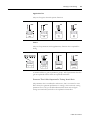
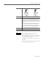
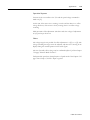
Throughout this manual, when necessary, we use notes to make you aware of safety considerations.
WARNING
IMPORTANT
CAUTION
Identifies information about practices or circumstances which may lead to serious personal injury or death, properity
damage, or economic loss.
Identifies information that is critical for successful application and understanding of the product.
Idnetifies information about proctives or circumstances that can lead to minor personal injury, properity damage,
ecconomic loss, or product malfuntion. However, depending on the situraiton, failutre to follow the directions
accompanying this symbol may also lead to serious consequences.
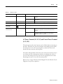
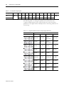
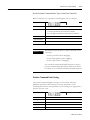
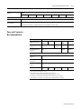
Summary of Change
You will see change bars to the left or right of a paragraph throughout this
manual to help you quickly indentify revisions.
Manual
Revision
Changes
Date
A
N/A
Jun 2011
1
CSD5 Servo Drive
SOC-2
Summary of Change
CSD5 Servo Drive
Table Of Contents
Summary of Change
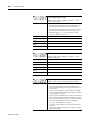
Preface
Who Should Use This Manual . . . . . . . . . . . . . . . . . . . . . . . . . . . . . . . . . . . .
About This Publication. . . . . . . . . . . . . . . . . . . . . . . . . . . . . . . . . . . . . . . . . .
Additional Resources . . . . . . . . . . . . . . . . . . . . . . . . . . . . . . . . . . . . . . . . . . .
Conventions Used in This Manual. . . . . . . . . . . . . . . . . . . . . . . . . . . . . . . . .
Table for Parameter Setting. . . . . . . . . . . . . . . . . . . . . . . . . . . . . . . . . . .
Terminology . . . . . . . . . . . . . . . . . . . . . . . . . . . . . . . . . . . . . . . . . . . . . . .
Notation Description. . . . . . . . . . . . . . . . . . . . . . . . . . . . . . . . . . . . . . . .
Manual Description Order . . . . . . . . . . . . . . . . . . . . . . . . . . . . . . . . . . .
Others. . . . . . . . . . . . . . . . . . . . . . . . . . . . . . . . . . . . . . . . . . . . . . . . . . . .
Safety Precautions . . . . . . . . . . . . . . . . . . . . . . . . . . . . . . . . . . . . . . . . . . . . . .
Usage . . . . . . . . . . . . . . . . . . . . . . . . . . . . . . . . . . . . . . . . . . . . . . . . . . .
Storage . . . . . . . . . . . . . . . . . . . . . . . . . . . . . . . . . . . . . . . . . . . . . . . . . . .
Transportation . . . . . . . . . . . . . . . . . . . . . . . . . . . . . . . . . . . . . . . . . . . .
Installation and Wiring . . . . . . . . . . . . . . . . . . . . . . . . . . . . . . . . . . . . .
Maintenance and Repair . . . . . . . . . . . . . . . . . . . . . . . . . . . . . . . . . . . . .
P-1
P-1
P-1
P-1
P-2
P-3
P-3
P-5
P-5
P-6
P-6
P-6
P-6
P-7
P-7
Chapter 1
Before Using the CSD5 Servo
Drive
Product Type and Each Part Name . . . . . . . . . . . . . . . . . . . . . . . . . . . . . . . .
Model Number of the Drive . . . . . . . . . . . . . . . . . . . . . . . . . . . . . . . . . . . . .
Name of Each Motor Part . . . . . . . . . . . . . . . . . . . . . . . . . . . . . . . . . . . . . . .
Model Number of the Motor . . . . . . . . . . . . . . . . . . . . . . . . . . . . . . . . . . . . .
1-1
1-2
1-3
1-4
Chapter 2
Installation
Servo Drive Installation . . . . . . . . . . . . . . . . . . . . . . . . . . . . . . . . . . . . . . . . .
Precautions . . . . . . . . . . . . . . . . . . . . . . . . . . . . . . . . . . . . . . . . . . . . . . . .
Installation Environment. . . . . . . . . . . . . . . . . . . . . . . . . . . . . . . . . . . . .
Servo Motor Installation. . . . . . . . . . . . . . . . . . . . . . . . . . . . . . . . . . . . . . . . .
2-1
2-1
2-4
2-4
Chapter 3
Wiring
i
Before You Begin . . . . . . . . . . . . . . . . . . . . . . . . . . . . . . . . . . . . . . . . . . . . . . 3-1
Electric Circuit . . . . . . . . . . . . . . . . . . . . . . . . . . . . . . . . . . . . . . . . . . . . . . . . 3-2
Name and Function . . . . . . . . . . . . . . . . . . . . . . . . . . . . . . . . . . . . . . . . . 3-2
AC Power Terminal (L1, L2, L3) and Control Power Terminal (L1C, L2C). . . 3-3
Regenerative Register Connection Port . . . . . . . . . . . . . . . . . . . . . . . . . 3-4
Electric Circuit Diagram . . . . . . . . . . . . . . . . . . . . . . . . . . . . . . . . . . . . . 3-5
Using the Socket and Lever. . . . . . . . . . . . . . . . . . . . . . . . . . . . . . . . . . . 3-6
I/O Signal (I/O) . . . . . . . . . . . . . . . . . . . . . . . . . . . . . . . . . . . . . . . . . . . . . . . 3-8
I/O Connection Diagram . . . . . . . . . . . . . . . . . . . . . . . . . . . . . . . . . . . . 3-8
(I/O) Input Signal. . . . . . . . . . . . . . . . . . . . . . . . . . . . . . . . . . . . . . . . . . . . . 3-10
Sequence Input Signal (Allocation) . . . . . . . . . . . . . . . . . . . . . . . . . . . . 3-10
General Input Signal (Fixed) . . . . . . . . . . . . . . . . . . . . . . . . . . . . . . . . . 3-11
(I/O) Output Signal . . . . . . . . . . . . . . . . . . . . . . . . . . . . . . . . . . . . . . . . . . . 3-13
Sequence Output Signal (Allocation) . . . . . . . . . . . . . . . . . . . . . . . . . . 3-13
General Output Signal (Fixed) . . . . . . . . . . . . . . . . . . . . . . . . . . . . . . . 3-14
(I/O) Input Circuit and Interface . . . . . . . . . . . . . . . . . . . . . . . . . . . . . . . . 3-16
CSD5 Servo Drive
ii
Pulse Command Input Circuit . . . . . . . . . . . . . . . . . . . . . . . . . . . . . . .
Analog Voltage Input Circuit . . . . . . . . . . . . . . . . . . . . . . . . . . . . . . . .
Sequence Input Circuit . . . . . . . . . . . . . . . . . . . . . . . . . . . . . . . . . . . . .
Emergency Stop Signal . . . . . . . . . . . . . . . . . . . . . . . . . . . . . . . . . . . . .
(I/O) Output Circuit and Interface . . . . . . . . . . . . . . . . . . . . . . . . . . . . . . .
Line Drive Output . . . . . . . . . . . . . . . . . . . . . . . . . . . . . . . . . . . . . . . . .
Photo-Coupler Output . . . . . . . . . . . . . . . . . . . . . . . . . . . . . . . . . . . . .
Encoder Wiring (Motor Feedback) . . . . . . . . . . . . . . . . . . . . . . . . . . . . . . .
Pin Arrangement of Motor Feedback. . . . . . . . . . . . . . . . . . . . . . . . . .
Terminal Type . . . . . . . . . . . . . . . . . . . . . . . . . . . . . . . . . . . . . . . . . . . .
Encoder Signal Process . . . . . . . . . . . . . . . . . . . . . . . . . . . . . . . . . . . . .
General Articles Wiring . . . . . . . . . . . . . . . . . . . . . . . . . . . . . . . . . . . . . . . .
Precautions . . . . . . . . . . . . . . . . . . . . . . . . . . . . . . . . . . . . . . . . . . . . . . .
Capacity of the Drive and Fuse. . . . . . . . . . . . . . . . . . . . . . . . . . . . . . .
Noise Protection . . . . . . . . . . . . . . . . . . . . . . . . . . . . . . . . . . . . . . . . . .
Wiring when Using Several Drives . . . . . . . . . . . . . . . . . . . . . . . . . . . .
Connection to Peripheral Equipment . . . . . . . . . . . . . . . . . . . . . . . . . .
3-16
3-17
3-18
3-19
3-20
3-20
3-20
3-22
3-22
3-23
3-24
3-27
3-27
3-28
3-29
3-33
3-34
Chapter 4
Operator, Basic Setting and
Startup
Before You Begin . . . . . . . . . . . . . . . . . . . . . . . . . . . . . . . . . . . . . . . . . . . . . . 4-1
About Servo-ON Signal . . . . . . . . . . . . . . . . . . . . . . . . . . . . . . . . . . . . . 4-1
Operator . . . . . . . . . . . . . . . . . . . . . . . . . . . . . . . . . . . . . . . . . . . . . . . . . . . . . 4-4
Name and Function of Each Part . . . . . . . . . . . . . . . . . . . . . . . . . . . . . . 4-4
Icons for the Key Buttons . . . . . . . . . . . . . . . . . . . . . . . . . . . . . . . . . . . . 4-4
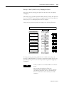
Structure of the Entire Mode . . . . . . . . . . . . . . . . . . . . . . . . . . . . . . . . . 4-5
Status Display Mode . . . . . . . . . . . . . . . . . . . . . . . . . . . . . . . . . . . . . . . . 4-7
Overview of the Parameter Setting Mode . . . . . . . . . . . . . . . . . . . . . . . 4-9
Overview of the Monitor Mode . . . . . . . . . . . . . . . . . . . . . . . . . . . . . . 4-10
Overview of the Operation Mode. . . . . . . . . . . . . . . . . . . . . . . . . . . . . 4-11
Basic Setting . . . . . . . . . . . . . . . . . . . . . . . . . . . . . . . . . . . . . . . . . . . . . . . . . 4-12
Overview of the Basic Setting . . . . . . . . . . . . . . . . . . . . . . . . . . . . . . . . 4-12
Control Mode Setting . . . . . . . . . . . . . . . . . . . . . . . . . . . . . . . . . . . . . . 4-13
Motor Setting . . . . . . . . . . . . . . . . . . . . . . . . . . . . . . . . . . . . . . . . . . . . . . . . 4-16
Startup . . . . . . . . . . . . . . . . . . . . . . . . . . . . . . . . . . . . . . . . . . . . . . . . . . . . . . 4-21
Before Startup . . . . . . . . . . . . . . . . . . . . . . . . . . . . . . . . . . . . . . . . . . . . 4-21
Startup . . . . . . . . . . . . . . . . . . . . . . . . . . . . . . . . . . . . . . . . . . . . . . . . . . 4-21
Chapter 5
Function for Control Mode
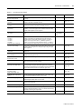
Sequence I/O (Input/Output) Signal . . . . . . . . . . . . . . . . . . . . . . . . . . . . . . 5-1
What is Sequence I/O Signal?. . . . . . . . . . . . . . . . . . . . . . . . . . . . . . . . . 5-1
Function of Input Signal . . . . . . . . . . . . . . . . . . . . . . . . . . . . . . . . . . . . . 5-2
Function of Output Signal. . . . . . . . . . . . . . . . . . . . . . . . . . . . . . . . . . . . 5-4
Input Signal Allocation Method . . . . . . . . . . . . . . . . . . . . . . . . . . . . . . . 5-5
Output Signal Allocation Method . . . . . . . . . . . . . . . . . . . . . . . . . . . . . . 5-7
Notice for Signal Allocation . . . . . . . . . . . . . . . . . . . . . . . . . . . . . . . . . . 5-8
Position Control Mode . . . . . . . . . . . . . . . . . . . . . . . . . . . . . . . . . . . . . . . . . 5-10
Overview . . . . . . . . . . . . . . . . . . . . . . . . . . . . . . . . . . . . . . . . . . . . . . . . 5-10
Standard Wiring Example . . . . . . . . . . . . . . . . . . . . . . . . . . . . . . . . . . . 5-11
iii
Position Command Pulse . . . . . . . . . . . . . . . . . . . . . . . . . . . . . . . . . . . 5-11
Position Command Pulse Setting . . . . . . . . . . . . . . . . . . . . . . . . . . . . . 5-15
Electrical Specifications of Position Command Pulse . . . . . . . . . . . . . 5-17
Electronic Gear . . . . . . . . . . . . . . . . . . . . . . . . . . . . . . . . . . . . . . . . . . . 5-18
Position Error Clear </PCLR> . . . . . . . . . . . . . . . . . . . . . . . . . . . . . . 5-25
Pulse Command Inhibition</INHIB> Input . . . . . . . . . . . . . . . . . . . 5-25
Expansion of Electronic Gear Setting . . . . . . . . . . . . . . . . . . . . . . . . . 5-26
The Second Group of Electronic Gear </GEAR> Input . . . . . . . . . 5-27
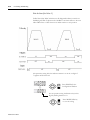
Position Completion Signal Detection </P-COM>, Approach Signal
Detection </NEAR> Output . . . . . . . . . . . . . . . . . . . . . . . . . . . . . . . 5-28
Output Width of Allowable Position Error . . . . . . . . . . . . . . . . . . . . . 5-31
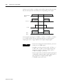
Input / Output Signal Timing Diagram . . . . . . . . . . . . . . . . . . . . . . . . 5-31
Speed Control Mode. . . . . . . . . . . . . . . . . . . . . . . . . . . . . . . . . . . . . . . . . . . 5-32
Overview . . . . . . . . . . . . . . . . . . . . . . . . . . . . . . . . . . . . . . . . . . . . . . . . 5-32
Standard Wiring Example . . . . . . . . . . . . . . . . . . . . . . . . . . . . . . . . . . . 5-33
Speed Command Input . . . . . . . . . . . . . . . . . . . . . . . . . . . . . . . . . . . . . 5-34
Zero Clamp </Z-CLP> Input . . . . . . . . . . . . . . . . . . . . . . . . . . . . . . . 5-35
Rotation Direction Switch Input </C-DIR> . . . . . . . . . . . . . . . . . . . 5-36
Motor Rotation Start/Stop Input</START>. . . . . . . . . . . . . . . . . . . 5-37
Speed Coincidence Output Signal </V-COM> . . . . . . . . . . . . . . . . . 5-38
Rotation Detection </TG-ON> Output . . . . . . . . . . . . . . . . . . . . . . 5-39
Speed Limit Function and Speed Limit Detection </V-LMT> Output . . . 5-41
Torque Control Mode. . . . . . . . . . . . . . . . . . . . . . . . . . . . . . . . . . . . . . . . . . 5-43
Overview . . . . . . . . . . . . . . . . . . . . . . . . . . . . . . . . . . . . . . . . . . . . . . . . 5-43
Standard Wiring Example . . . . . . . . . . . . . . . . . . . . . . . . . . . . . . . . . . . 5-44
Torque Command Input . . . . . . . . . . . . . . . . . . . . . . . . . . . . . . . . . . . . 5-44
Torque Limit and Torque Limit Detection </T-LMT> Output . . . . 5-46
Multi-Step Speed Mode . . . . . . . . . . . . . . . . . . . . . . . . . . . . . . . . . . . . . . . . 5-51
Overview . . . . . . . . . . . . . . . . . . . . . . . . . . . . . . . . . . . . . . . . . . . . . . . . 5-51
Standard Wiring Example . . . . . . . . . . . . . . . . . . . . . . . . . . . . . . . . . . . 5-52
Multi-Step Speed Command Setting . . . . . . . . . . . . . . . . . . . . . . . . . . . 5-52
Mixed Control Mode and </C-SEL> Function . . . . . . . . . . . . . . . . . . . . . 5-56
Chapter 6
Tuning by Gain Setting
Before You Begin . . . . . . . . . . . . . . . . . . . . . . . . . . . . . . . . . . . . . . . . . . . . . . 6-1
Mark Description . . . . . . . . . . . . . . . . . . . . . . . . . . . . . . . . . . . . . . . . . . . 6-1
Gain Introduction . . . . . . . . . . . . . . . . . . . . . . . . . . . . . . . . . . . . . . . . . . 6-1
Inertia Ratio . . . . . . . . . . . . . . . . . . . . . . . . . . . . . . . . . . . . . . . . . . . . . . . 6-4
Gain Setting Configuration. . . . . . . . . . . . . . . . . . . . . . . . . . . . . . . . . . . . . . . 6-5
Auto Gain Setting . . . . . . . . . . . . . . . . . . . . . . . . . . . . . . . . . . . . . . . . . . . . . . 6-8
Auto Tuning . . . . . . . . . . . . . . . . . . . . . . . . . . . . . . . . . . . . . . . . . . . . . . . 6-8
Off-line Auto Tuning. . . . . . . . . . . . . . . . . . . . . . . . . . . . . . . . . . . . . . . . 6-8
On-line Auto Tuning . . . . . . . . . . . . . . . . . . . . . . . . . . . . . . . . . . . . . . . 6-10
On-line Vibration Suppression . . . . . . . . . . . . . . . . . . . . . . . . . . . . . . . 6-11
Online Vibration Suppression Gain Setting . . . . . . . . . . . . . . . . . . . . . 6-13
Manual Gain Setting . . . . . . . . . . . . . . . . . . . . . . . . . . . . . . . . . . . . . . . . . . . 6-14
Gain Setting Flowchart . . . . . . . . . . . . . . . . . . . . . . . . . . . . . . . . . . . . . 6-14
Basic Gain Setting . . . . . . . . . . . . . . . . . . . . . . . . . . . . . . . . . . . . . . . . . 6-15
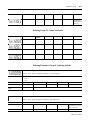
Position, Speed, Torque Related Gain Setting. . . . . . . . . . . . . . . . . . . . . . . 6-18
iv
Torque Control Related Gain . . . . . . . . . . . . . . . . . . . . . . . . . . . . . . . .
Speed Control Related Gain . . . . . . . . . . . . . . . . . . . . . . . . . . . . . . . . .
Position Control Related Gain . . . . . . . . . . . . . . . . . . . . . . . . . . . . . . .
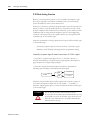
Tip to get fast response . . . . . . . . . . . . . . . . . . . . . . . . . . . . . . . . . . . . . . . .
Feedforward function . . . . . . . . . . . . . . . . . . . . . . . . . . . . . . . . . . . . . .
Speed Bias Function . . . . . . . . . . . . . . . . . . . . . . . . . . . . . . . . . . . . . . .
P/PI Mode Setting Function. . . . . . . . . . . . . . . . . . . . . . . . . . . . . . . . .
Initial Torque Bias . . . . . . . . . . . . . . . . . . . . . . . . . . . . . . . . . . . . . . . . .
</G-SEL> Function. . . . . . . . . . . . . . . . . . . . . . . . . . . . . . . . . . . . . . .
Gain Switching Function . . . . . . . . . . . . . . . . . . . . . . . . . . . . . . . . . . . .
6-19
6-21
6-25
6-27
6-27
6-28
6-30
6-33
6-36
6-37
Chapter 7
Applications
Motor Suspension . . . . . . . . . . . . . . . . . . . . . . . . . . . . . . . . . . . . . . . . . . . . . . 7-1
Overview . . . . . . . . . . . . . . . . . . . . . . . . . . . . . . . . . . . . . . . . . . . . . . . . . 7-1
Servo Alarm . . . . . . . . . . . . . . . . . . . . . . . . . . . . . . . . . . . . . . . . . . . . . . . 7-1
OverTravel <P-OT>, <N-OT>. . . . . . . . . . . . . . . . . . . . . . . . . . . . . . . 7-2
Dynamic Brake. . . . . . . . . . . . . . . . . . . . . . . . . . . . . . . . . . . . . . . . . . . . . 7-3
Motor Brake Contorl . . . . . . . . . . . . . . . . . . . . . . . . . . . . . . . . . . . . . . . . . . . 7-6
Change the Motor Rotation Direction. . . . . . . . . . . . . . . . . . . . . . . . . . . . . 7-11
Reneration Resister . . . . . . . . . . . . . . . . . . . . . . . . . . . . . . . . . . . . . . . . . . . . 7-12
Reneration Resister . . . . . . . . . . . . . . . . . . . . . . . . . . . . . . . . . . . . . . . . 7-12
External Regenerative Resistor . . . . . . . . . . . . . . . . . . . . . . . . . . . . . . . 7-13
Regenerative Resistor Selection Standard . . . . . . . . . . . . . . . . . . . . . . . 7-14
Setting for Smooth Operation . . . . . . . . . . . . . . . . . . . . . . . . . . . . . . . . . . . 7-17
Speed Limiting Function . . . . . . . . . . . . . . . . . . . . . . . . . . . . . . . . . . . . . . . 7-21
Postion Feedback to the Host Controller . . . . . . . . . . . . . . . . . . . . . . . . . . 7-24
Overview . . . . . . . . . . . . . . . . . . . . . . . . . . . . . . . . . . . . . . . . . . . . . . . . 7-24
Direction Change of Output Pulse . . . . . . . . . . . . . . . . . . . . . . . . . . . . 7-24
Pulse Dividing Circuit . . . . . . . . . . . . . . . . . . . . . . . . . . . . . . . . . . . . . . 7-25
Analog Monitor Output . . . . . . . . . . . . . . . . . . . . . . . . . . . . . . . . . . . . . . . . 7-28
Use of Absolute Encoder . . . . . . . . . . . . . . . . . . . . . . . . . . . . . . . . . . . . . . . 7-31
What is an Absolute Encoder? . . . . . . . . . . . . . . . . . . . . . . . . . . . . . . . 7-31
Contact with the Host Controller . . . . . . . . . . . . . . . . . . . . . . . . . . . . . 7-32
Battery. . . . . . . . . . . . . . . . . . . . . . . . . . . . . . . . . . . . . . . . . . . . . . . . . . . 7-33
Reset of Absolute Encoder . . . . . . . . . . . . . . . . . . . . . . . . . . . . . . . . . . 7-34
Data Transmission of Absolute Encoder . . . . . . . . . . . . . . . . . . . . . . . 7-36
Operation Mode Function . . . . . . . . . . . . . . . . . . . . . . . . . . . . . . . . . . . . . . 7-41
Things to Know First . . . . . . . . . . . . . . . . . . . . . . . . . . . . . . . . . . . . . . 7-41
Jog Operation (run-00) . . . . . . . . . . . . . . . . . . . . . . . . . . . . . . . . . . . . . 7-41
Off-line Auto Tuning Operation (run-01) . . . . . . . . . . . . . . . . . . . . . . 7-43
Auto Adjustment of Speed Command Offset (run-03) . . . . . . . . . . . . 7-44
Auto Adjustment of Torque Command Offset (run-04). . . . . . . . . . . 7-46
Alarm Reset (run-08) . . . . . . . . . . . . . . . . . . . . . . . . . . . . . . . . . . . . . . . 7-49
Absolute Encoder Reset (run-10) . . . . . . . . . . . . . . . . . . . . . . . . . . . . . 7-50
2-Group Gain Storing (run-11) . . . . . . . . . . . . . . . . . . . . . . . . . . . . . . . 7-50
Parameter Initialization (run-12) . . . . . . . . . . . . . . . . . . . . . . . . . . . . . . 7-50
Monitor Mode Function. . . . . . . . . . . . . . . . . . . . . . . . . . . . . . . . . . . . . . . . 7-52
Monitor Mode Function . . . . . . . . . . . . . . . . . . . . . . . . . . . . . . . . . . . . 7-54
Key Button Operation . . . . . . . . . . . . . . . . . . . . . . . . . . . . . . . . . . . . . . 7-55
v
Chapter 8
Inspection and Protection
Functions
Inspection . . . . . . . . . . . . . . . . . . . . . . . . . . . . . . . . . . . . . . . . . . . . . . . . . . . .
Inspection of Motor. . . . . . . . . . . . . . . . . . . . . . . . . . . . . . . . . . . . . . . . .
Inspection of Drive . . . . . . . . . . . . . . . . . . . . . . . . . . . . . . . . . . . . . . . . .
Part Inspection . . . . . . . . . . . . . . . . . . . . . . . . . . . . . . . . . . . . . . . . . . . . .
Battery Inspection for Absolute Encoder. . . . . . . . . . . . . . . . . . . . . . . .
Protection Function . . . . . . . . . . . . . . . . . . . . . . . . . . . . . . . . . . . . . . . . . . . .
Servo Warning . . . . . . . . . . . . . . . . . . . . . . . . . . . . . . . . . . . . . . . . . . . . .
Servo Alarm . . . . . . . . . . . . . . . . . . . . . . . . . . . . . . . . . . . . . . . . . . . . . . .
Confirmation before Requesting for A/S. . . . . . . . . . . . . . . . . . . . . . . .
8-1
8-1
8-2
8-2
8-3
8-3
8-3
8-5
8-9
Appedix B
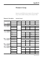
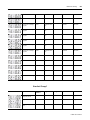
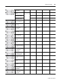
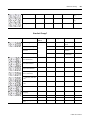
Parameter Group
Parameter Description . . . . . . . . . . . . . . . . . . . . . . . . . . . . . . . . . . . . . . . . . . B-1
Standard Group 0 . . . . . . . . . . . . . . . . . . . . . . . . . . . . . . . . . . . . . . . . . . B-1
Standard Group 1 . . . . . . . . . . . . . . . . . . . . . . . . . . . . . . . . . . . . . . . . . . B-3
Standard Group 2 . . . . . . . . . . . . . . . . . . . . . . . . . . . . . . . . . . . . . . . . . . B-6
Standard Group 3 . . . . . . . . . . . . . . . . . . . . . . . . . . . . . . . . . . . . . . . . . . B-7
Standard Group 4 . . . . . . . . . . . . . . . . . . . . . . . . . . . . . . . . . . . . . . . . . . B-7
Standard Group 5 . . . . . . . . . . . . . . . . . . . . . . . . . . . . . . . . . . . . . . . . . . B-8
Parameter Description . . . . . . . . . . . . . . . . . . . . . . . . . . . . . . . . . . . . . . . . . . B-9
Standard Group 0 . . . . . . . . . . . . . . . . . . . . . . . . . . . . . . . . . . . . . . . . . . B-9
Standard Group 1 . . . . . . . . . . . . . . . . . . . . . . . . . . . . . . . . . . . . . . . . . B-25
Standard Group 2 . . . . . . . . . . . . . . . . . . . . . . . . . . . . . . . . . . . . . . . . . B-38
Standard Group 3 . . . . . . . . . . . . . . . . . . . . . . . . . . . . . . . . . . . . . . . . . B-42
Standard Group 4 . . . . . . . . . . . . . . . . . . . . . . . . . . . . . . . . . . . . . . . . . B-47
Standard Group 5 . . . . . . . . . . . . . . . . . . . . . . . . . . . . . . . . . . . . . . . . . B-49
Indexing Drive Parameters. . . . . . . . . . . . . . . . . . . . . . . . . . . . . . . . . . . . . . B-53
Indexing Group 0 - Indexing System . . . . . . . . . . . . . . . . . . . . . . . . . . B-53
Indexing Group 1 - Homing . . . . . . . . . . . . . . . . . . . . . . . . . . . . . . . . . B-54
Indexing Group 2- Index Option . . . . . . . . . . . . . . . . . . . . . . . . . . . . . B-54
Indexing Gorup 4 - Index Position/Distance . . . . . . . . . . . . . . . . . . . B-55
Indexing Group 7 - Index Dwell. . . . . . . . . . . . . . . . . . . . . . . . . . . . . . B-55
Indexing Gorup 8 - Index Velocity. . . . . . . . . . . . . . . . . . . . . . . . . . . . B-56
Indexing Group 10 - Index Acceleration . . . . . . . . . . . . . . . . . . . . . . . B-56
Indexing Gorup 11 - Index Deceleration . . . . . . . . . . . . . . . . . . . . . . . B-56
Indexing Gorup 12 - Index Next Index . . . . . . . . . . . . . . . . . . . . . . . . B-57
Indexing Parameter Gorup 0 - Indexing System . . . . . . . . . . . . . . . . . B-57
Indexing Parameter Garoup 1 - Homing . . . . . . . . . . . . . . . . . . . . . . . B-59
Indexing Parameter Group 2 - Indexing Options . . . . . . . . . . . . . . . . B-62
Indexing Parameter Group 4 - Index Position/Distance . . . . . . . . . . B-63
Indexing Parameter Group 7 - Index Dwell. . . . . . . . . . . . . . . . . . . . . B-63
Indexing Parameter Group 8 - Index Velocity . . . . . . . . . . . . . . . . . . . B-63
Indexing Parameter Group 10 - Index Acceleration . . . . . . . . . . . . . . B-63
Indexing Parameter Group 10 - Index Deceleration . . . . . . . . . . . . . . B-64
Indexing Parameter Group 12 - Index Next Index . . . . . . . . . . . . . . . B-64
Run Parameter. . . . . . . . . . . . . . . . . . . . . . . . . . . . . . . . . . . . . . . . . . . . . . . . B-64
Display Parameter . . . . . . . . . . . . . . . . . . . . . . . . . . . . . . . . . . . . . . . . . . . . . B-65
Warning and DRive Display. . . . . . . . . . . . . . . . . . . . . . . . . . . . . . . . . . . . . B-65
vi
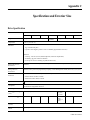
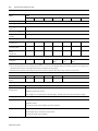
Appedix C
Specification and Exterior Size
Drive Specification . . . . . . . . . . . . . . . . . . . . . . . . . . . . . . . . . . . . . . . . . . . . .
Fuse and Contactor Recommendations . . . . . . . . . . . . . . . . . . . . . . . . . . . .
Accessaries . . . . . . . . . . . . . . . . . . . . . . . . . . . . . . . . . . . . . . . . . . . . . . . . . . .
Drive Size and Exterial View . . . . . . . . . . . . . . . . . . . . . . . . . . . . . . . . . . . . .
C-1
C-3
C-4
C-4
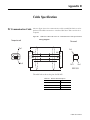
Appedix D
Cable Specification
PC Communication Cable . . . . . . . . . . . . . . . . . . . . . . . . . . . . . . . . . . . . . . D-1
Appedix E
I/O Setting and Indexing
Overivew . . . . . . . . . . . . . . . . . . . . . . . . . . . . . . . . . . . . . . . . . . . . . . . . . . . . . E-1
I/O Input Signal . . . . . . . . . . . . . . . . . . . . . . . . . . . . . . . . . . . . . . . . . . . . . . E-1
I/O Sequence Input Signal . . . . . . . . . . . . . . . . . . . . . . . . . . . . . . . . . . . E-1
Factory Default . . . . . . . . . . . . . . . . . . . . . . . . . . . . . . . . . . . . . . . . . . . . E-6
I/O Setting . . . . . . . . . . . . . . . . . . . . . . . . . . . . . . . . . . . . . . . . . . . . . . . . . . . E-7
Input Signal Allocation . . . . . . . . . . . . . . . . . . . . . . . . . . . . . . . . . . . . . . E-7
Output Signal Allocation . . . . . . . . . . . . . . . . . . . . . . . . . . . . . . . . . . . . . E-8
I/O Signal Description. . . . . . . . . . . . . . . . . . . . . . . . . . . . . . . . . . . . . . . . . . E-9
START and IMO (In Motion) . . . . . . . . . . . . . . . . . . . . . . . . . . . . . . . . E-9
I_SEL0~5 (Index Selection 0~5 Input) . . . . . . . . . . . . . . . . . . . . . . . . E-10
O_ISEL0~5(Index Selection 0~5 Output) . . . . . . . . . . . . . . . . . . . . . E-10
PAUSE(Index Pause). . . . . . . . . . . . . . . . . . . . . . . . . . . . . . . . . . . . . . . E-11
STOP (Index Stop) . . . . . . . . . . . . . . . . . . . . . . . . . . . . . . . . . . . . . . . . E-13
SHOM (Start Home), HOME (Home Sensor), HOMC (Axis Home). . . . E-14
Index Operation Options . . . . . . . . . . . . . . . . . . . . . . . . . . . . . . . . . . . . . . . E-15
Operation Setting after Index Movement (Action When Complete) . . E-16
Homing types . . . . . . . . . . . . . . . . . . . . . . . . . . . . . . . . . . . . . . . . . . . . . E-21
Homing Velocity . . . . . . . . . . . . . . . . . . . . . . . . . . . . . . . . . . . . . . . . . . E-26
S/W Limit . . . . . . . . . . . . . . . . . . . . . . . . . . . . . . . . . . . . . . . . . . . . . . . . . . . E-28
Dwell Time . . . . . . . . . . . . . . . . . . . . . . . . . . . . . . . . . . . . . . . . . . . . . . . . . . E-28
RUN . . . . . . . . . . . . . . . . . . . . . . . . . . . . . . . . . . . . . . . . . . . . . . . . . . . . . . . E-29
Index Alarm . . . . . . . . . . . . . . . . . . . . . . . . . . . . . . . . . . . . . . . . . . . . . . . . . E-30
Home Searching Failed. . . . . . . . . . . . . . . . . . . . . . . . . . . . . . . . . . . . . . . . . E-30
Axis not homed. . . . . . . . . . . . . . . . . . . . . . . . . . . . . . . . . . . . . . . . . . . . . . . E-30
Index Position Overflow . . . . . . . . . . . . . . . . . . . . . . . . . . . . . . . . . . . . E-30
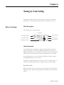
Preface
Read this preface to familiarize you with the rest of the manual.
Who Should Use This
Manual
•
Who Should Use This Manual
•
About This Publication
•
Additional Resources
•
Conventions Used in This Manual
•
Safety Precautions
This manual is intended for engineers or technicians directly involved in the
installation and wiring of the CSD5 servo drive, and programmers directly
involved in the operation, field maintenance, and integration of the CSD5
servo drive with a Motion Card.
If you do not have a basic understanding of the CSD5 servo drive, contact
your local RS Automation sales representative before using this product, for
information on available training courses.
About This Publication
This manual provides detailed installation instructions for mounting, wiring,
and troubleshooting your CSD5 servo drive, and system integration for your
drive/motor combination with a Motion Card.
Additional Resources
The following documents contain additional information concerning related
CSD5 servo drive products.You can view or download publications at
www.rsautomation.biz
To order paper copies of technical documentation, contact your local RS
Automation Korea distributor or sales representative.
Conventions Used in This
Manual
1
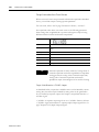
For
Read This Document
Information on the installation of your
CSD5 servo drive
CSD5 Servo Drive Installation Instructions
Information on the motors used together
with CSD5 servo drive
Servo Motor User Manual
The conventions starting below are used throughout this manual.
•
Bulleted lists such as this one provide information, not procedural steps
•
Numbered lists provide sequential steps or hierarchical information
CSD5 Servo Drive
P-2
Preface
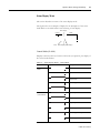
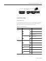
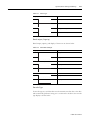
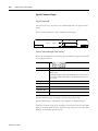
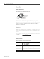
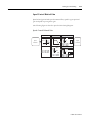
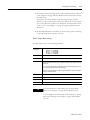
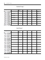
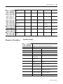
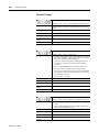
Table for Parameter Setting
This manual uses the following table for parameter description.
Example of Parameter Setting
Parameter
Parameter Name
Motor Forward Direction
Description
You can choose the rotational direction of the motor
Setting Value
• 0: CW
• 1: CCW
Initial Value
0
Applicable Mode
All
Others
Servo-OFF > Setting > End
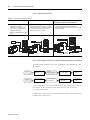
Table Description
Parameter: at the top-left side shows the parameter being described.
The setting window on the right of the parameter, is entered when the
ENTER key is pressed. The parameter must be set from the digit in black
color and the initial value shows the initial value of the parameter.
It is classified into a parameter selected among already set values (“selected
parameter”) and a parameter, which the users give appropriate value. The
selected parameter, as shown in the example above, displays both parameter
and setting window, and the latter parameter displays only the parameter and
not eh setting window.
Parameter Name: describes the value selectable by the user and the selected
value.
Description: describes the function and usage of parameter.
Setting Value: describes the value selectable by the user and the selected
value.
Initial Value: Initial Value displayed when the parameter is selected.
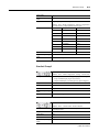
Applicable Mode: alphabetically displays the corresponding control mode in
setting parameter, and displays (ALL) if all are included.
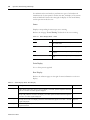
CSD5 Servo Drive
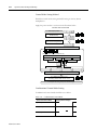
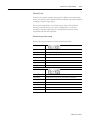
Mode
Position mode
Speed mode
Torque mode
Multi-step speed mode
Displa
y
F
S
C
P
Preface
P-3
Combinational control mode indicates the alphabets of two modes, combined
in a row.
ex) speed + position mode (SF), torque-speed mode (tS).
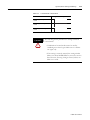
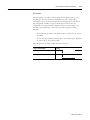
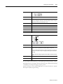
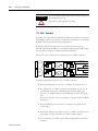
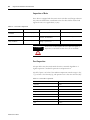
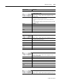
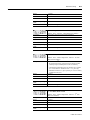
Others: normally, as described in an example of automobile, the driver cannot
manipulate parking brake of a running automobile, and the servo drive also
should be divided into Servo-ON status and Servo-OFF status when setting
the parameter.
Others
Description
Setting > End
Set regardless of the drive status.
Servo-OFF > Setting > End
Set it in Servo-OFF status
Servo-OFF > Setting > Power Off &
On > End
Set it in Serve-OFF status, and apply the power
again
Terminology
The following describes terminologies used in this manual.
• Servo Drive or Drive: Refer to the CSD5 Servo Drive
• Servo Motor or Motor: Refer to the servo motor exclusively for the
CSD5 drive.
• Host Controller : Refers to a controller or a device that gives
command to the drive and controls it.
• Initial Value: Refer to the value set at the factory before the
shipment.
• Setting Value: Refers to the initial value or the value changed and set
by the users.
• User’s Manual: Simply indicated as ‘manual’.
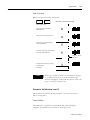
Notation Description
Within the sentences of this manual, the following is expressed as shown
below. Be fully aware of them when using the servo drive.
1. Use ‘/’ in front of Active Low signal.
3
CSD5 Servo Drive
P-4
Preface
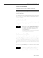
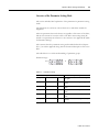
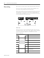
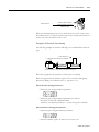
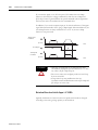
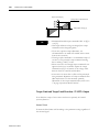
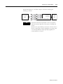
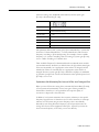
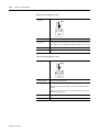
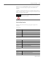
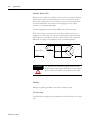
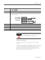
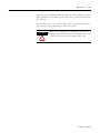
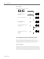
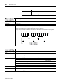
2. A figure box with both the top corners cut off diagonally represents a
circuit diagram. If I/O for I/O signal or a connector attached to the
servo driver is on the left, it is the output of I/O or servo drive.
Output
Example
R1
I/O
0[v]
Host Controller
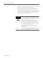
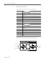
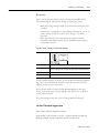
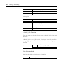
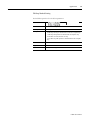
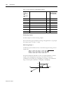
3. If I/O for I/O signal or a connector attached to servo driver is on
the right, it is the input from the host controller to I/O or servo
drive.
Input
Example
Speed Command
-10[v] ~ +10[v]
P
VCMD+
19
VCMD-
20
I/O
Host Controller
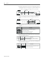
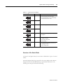
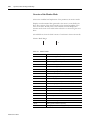
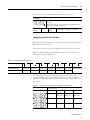
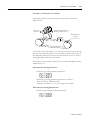
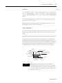
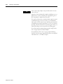
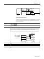
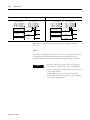
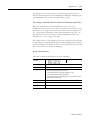
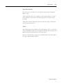
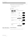
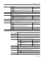
4. The following shows the symbols used on the circuit
diagram.
Signal
A
Description
B
1
1
2
2
3
3
Contact Point
The figure represents the pin number of the
connector, which can be marked with alphabets
tather than the numbers.
The contact is the connection between
the side A and B with the connector.
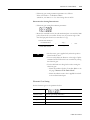
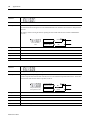
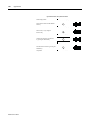
5. The following figure shows a symbol used to show a twist pair wires
to prevent the noise generation.
Signal
Figure
Description
The the wires where this symbol is located for
the noise prevention.
P
6. The following figure shows a symbol used to show a shield pair wire
to prevent the noise generation.
Signal
Figure
FG
Shield
CSD5 Servo Drive
Description
Shield the wires where this symbol is located
for the noise prevention.
Preface
P-5
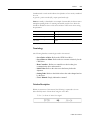
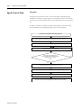
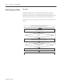
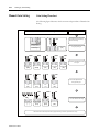
Manual Description Order
This manual is described in the view of users from the purchase to operation.
1. Descripbes things to know before using the product.
2. Describes the outline of product and marking.
3. Describes precations upon product installation.
4. Describes wiring with the host controller and peripheral
equipment.
5. Describes the operator for various settings.
6. Describes brief functions of the product.
7. Describes the basic settings that users should set.
8. Describes the fucntion of the product for each control modes.
9. Describes the tuning to implement optimum performance of load
system.
10.Describes simple supplementary functions.
11.Describes the protective function, fault diagnosis and
troubleshooting.
12.Describes items corresponding to various numerical data in the
Appendix.
Others
Each chapter or paragraph has a page called before you begin before
description. For easier understanding of this manual, be fully aware of the
contents of this page called before you begin in advance.
5
CSD5 Servo Drive
P-6
Preface
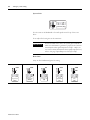
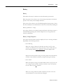
Safety Precautions
This is CSD5 User Manual describes safety matters using the following marks.
Safety marks deals with the important matters. If the following marks and
contents of each mark are indicated in the contents of this user's manual, you
must be fully aware of them and follow them.
Usage
CAUTION
WARNING
• Do not touch the inside of servo drive.
• Make sure that the servo drive and the motor are fully
grounded.
• Completely discharged before handling after power
off.
• Do not put excessive stress on the motor power and
encoder cable.
• Never touch the revolving part of the motor during
operation .
• Avoid using the product near wet places or corrosive
and inflammable materials.
• Operate the system with no load during pilot
operation.
• Never touch the heat sink directly.
Storage
WARNING
• Do not store the product near wet places, rain, toxic
gas or fluid.
• Keep the product out of the direct rays of the sun and
store it within the storage temperature and humidity
ranges.
• Avoid overloading if the product is stored in a
warehouse.
Transportation
WARNING
CSD5 Servo Drive
• Do not carry the product by holding the cable and the
motor shaft.
Preface
P-7
Installation and Wiring
WARNING
CAUTION
• Install a cooling fan to prevent excessive temperature
increase. (Refer to the Chapter 2)
• Be careful not to wiring cables around the heat sink.
• Install drives with regular space (at least 10 mm)
between them.
• Pay attention to the heat sink when wiring. (Refer to
Chapter 2)
Maintenance and Repair
WARNING
7
• Do not disassemble or remodel the product. Any
damage caused after the user disassembles or
remodels the product will be excluded from the
company's warranty.
• The company bears no responsibility for injuries or
physical damage caused by remodeling of this
product.
• Life-limited Parts by mechanical friction or heat
requires regular . Refer to the Chapter 8.
• In case of a failure that cannot be dealt with, please
contact the company’ s technical support team or
after-sales service center.
CSD5 Servo Drive
P-8
Preface
CSD5 Servo Drive
Chapter 1
Before Using the CSD5 Servo Drive
This chapter describes the general matters and optional specifications that you
should know before using the CSD5 SERVO DRIVE.
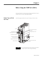
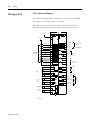
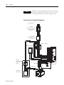
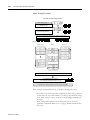
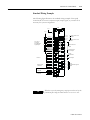
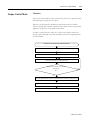
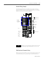
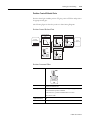
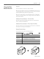
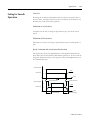
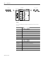
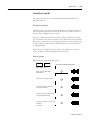
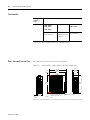
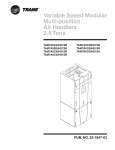
Product Type and Each
Part Name
The following figure introduces the name of each part of the servo drive.
Operator
Communication and Operator
Connector
Analog Output Terminal
I/O Signal Connector <I/O>
Terminating Resistance Setting
AC Main Power Input Terminal
Control Power Input Terminal
Drive Nameplate
DC Link Negative Output
Regenerative Resistor Terminal
Motor Cable Terminal
TIP
1
Encoder Cable Connector <Motor
Feedback>
For more detail information about Operator, please refer to
“ Chapter 4 Operator, Basic Setting and Startup”.
CSD5 Servo Drive
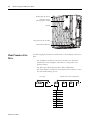
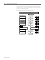
1-2
Before Using the CSD5 Servo Drive
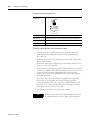
Mounting Hall (Top, Bottom)
Regenerative Resistor
(400 [W] or Higher Attached)
Heat Sink
Wiring Socket (6P, 2P, 3P) 3 PART
Ground Terminal (Heat Sink)
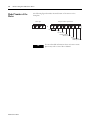
Model Number of the
Drive
The following figure describes the model name on the nameplate of the servo
drive.
• The nameplate is attached on the side of the drive case. Check the
model name on the nameplate, and check if it corresponds to the
product ordered.
• The drive type is RS Automation Servo Drive CSD5 Series.
• The serial number is included on the nameplate. Be careful not to erase
the serial number during the use.
Drive Type
CSD
KNX
Example of Servo Drvicve Specification
3
5
- A5
K
Mask
CSD5 Servo Drive
Rated
A5
50 [W]
01
100 [W]
02
200 [W]
04
400 [W]
08
800 [W]
10
1 [kW]
15
1.5 [kW]
B
A
X
P
1
0
Before Using the CSD5 Servo Drive
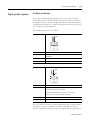
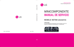
Name of Each Motor Part
1-3
The following figure shows the name of each more part.
A motor without a brake does not have a brake cable. The name of each motor
part may differ from the following figure according to the motor type.
TIP
For more detailed infroamtion about Servo Motor, please
refer to “ Servo Motor Manual” .
Break Cable
Motor Cable
Encoder Cable
Encoder
Motor Nameplate
Motor Frame
Motor Shaft
Mounting Hole
TIP
RS Automation does not provide cables. For more
information about specification and order code of cables
below, refer to "Servo Motor Manual (Publication
SMOTOR-UM002)".
• Motor 3 phase Power Cable
• Encoder Cable
• Motor Break Cable
• I/O Cable
• Communication Cable
3
CSD5 Servo Drive
1-4
Before Using the CSD5 Servo Drive
Model Number of the
Motor
The following figure describes the model name of the motor on the
nameplate.
Motor Type
C S M T
Example of Motor Specifcation
-
0 1 B B 1 A N T
Rated Output
3
Voltage
Encoder Type
Design Sequence
Motor Axis Key
Option
Manufacturer
Shaft Specification
TIP
CSD5 Servo Drive
For more detailed information about each motor name
plate items, refer to Servo Motor Manual.
Chapter 2
Installation
This chapter describes matters to consider when installing the servo drive and
the motor. Refer to the appendix for numerical data on the drive, motor, and
various peripheral equipments necessary for the installation.
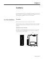
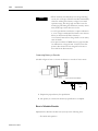
Servo Drive Installation
Precautions
Refer to the following figures when installing the servo drive.
The most important thing to consider when installing the drive is the ambient
temperature. Follow the operational temperature and mount the servo drive
vertically.
Install the Servo Drive Vertically
Servo drive less than 400 [W] applies the natural convective cooling, and the
servo drive with more than 0.8 [kW] uses the cooling fan. To increase the
cooling efficiency, install it vertically.
Natural
Natural
1
CSD5 Servo Drive
2-2
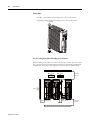
Installation
Fixing Bolt
• 400 [W] or less: M4xL1 0 mounting holes at the top & bottom
• 0.8 [kW] or more: M5xL10 mounting holes at the top & bottom
Fixing Bolt
Fixing Bolt
Use A Cooling Fan When Installing Several Drives.
When installing several drives, you must the following criteria. Install a cooling
fan to prevent excessive temperature increase.If the surrounding temperature
is higher than the operational temperature, it may reduce the performance.
Cooling Fan
Cooling Fan
More than
50 [mm]
Panel
More than 30 [mm]
CSD5 Servo Drive
More than 10
More than
50 [mm]
Installation
2-3
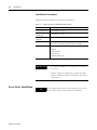
Use the Drive in a Clean Environment
Use the drive in a clean environment where there is no dust or humidity.
Ground
There is a grounding terminal at the bottom of the heat sink.
• 200 [W] or less: 1 mounting hole for M4 BOLT
• 400 [W] or above: 2 mounting holes for M4 BOLT
If not grounded, it may reduce the performance.
3
CSD5 Servo Drive
2-4
Installation
Installation Environment
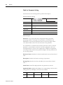
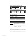
CSD5 Servo Drive installation environment is like below.
Table 2.1
CSD5 Servo Drive Installation Environment
Item
Installation Environment
Storing Temperature
Store it within -25 ~ 85 [℃]
Operational
Temperature
Use it within 0 ~ 50 [℃]
Operational
Humidity
Use it below 5 ~ 95 [%] RH at a place without condensations
Vibration
5-55Hz @ 0.35mm(0.014") double amplitude, continuous
displacement, 55-500Hz @ 2g peak constant acceleration
Operational Location Installation environment must meet the follwoing conditions:
• Indoors
• Well ventilation
• Easy checkup
• Without explosive gas
IMPORTANT
• To maintain reliability for a long time, use it within to
0~35 [℃].
• Install a separate cooling device at a place with high
ambient temperature and use it within the operational
temperature.
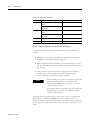
Servo Motor Installation
TIP
CSD5 Servo Drive
For numerical data related to the installation of the servo
motor, please refer to Servo Motor User Manual.
Chapter 3
Wiring
This chapter describes the information on motor, host controller and
other wiring connected to the servo drive, along with the circuit
diagram.
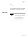
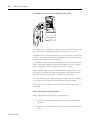
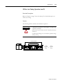
Before You Begin
Pay attention to the following precautions when wiring.
CAUTION
• Wiring should be done only by the qualified personal.
• High voltage remains in the drive even through the
power is off. Therefore, do not inspect components
unless inside Charge lamp is off.
• Pay attention to the polarity when wiring.
• The heat sink of the drive generates high heat. Pay
attention to the heat sink when wiring.
1
CSD5 Servo Drive
3-2
Wiring
In this chapter, the circuit is divided into electric circuit and signal
circuit for easier and convenient explanation. Be fully aware of the
names of each terminal when reading this user’s manual.
Operator
Communication and Operator
Connector
Analog Output Terminal
I/O Signal Connector <I/O>
RS485 Terminating Resistance Setting
AC Main Power Input Terminal
Contor Power Input Terminal
Drive Nameplate
DC Link Negative Output
Regenerative Resistor Terminal
Motor Cable Terminal
Encoder Cable Connector
<Motor Feedback>
The I/O signal connector I/O and encoder cable connector Motor
Feedback are included only in the description of the signal circuit. The
description of other connectors and omitted.
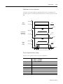
Electric Circuit
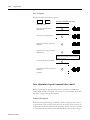
Name and Function
The terminal symbol is printed on the wiring socket at the electric
circuit terminal of the drive. Observe the drive to identify and
understand the terminals on the following table, and then wire
accordingly.
CSD5 Servo Drive
Wiring
Table 3.1
3-3
Electric Circuit
Terminal
Terminal Symbol
Purpose
AC Power Terminal
L1, L2, L3
400 [W] or lower
Single phase 200 ~ 240 [V] (50/60 [Hz]) (L3 port must not
be used)
800 [W] or higher
3 phase 200 ~ 240 [V] (50/60 [Hz]) (800 [W] can be used as
Single phase )
Single phase 200 ~ 240 [V] (50/60 [Hz])
Control Power Terminal
L1C, L2C
No output division
Motor Cable Terminal
U, V, W
Connect the motor cable.
Grounding Terminal
(Heat Sink)
Regenerative Register
Connection Port
Connect the power and motor cable to the grounding terminal.
B1, B2
200 [W] or lower
As the function for regenerative energy consumption is not
required, the regenerative resistor does not have to be
mounted.
400 [W] or higher
If the capacity of mounted regenerative resistor is
insufficient, remove it or connect it to the mounted
regenerative resistor in parallel.
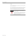
AC Power Terminal (L1, L2, L3) and Control Power Terminal
(L1C, L2C)
The main power and control power can be divided when connecting to
the drive. Therefore, the user can configure surrounding circuits when
the main power is cut off in an emergency or when the drive itself
checks the status and cuts off the power.
If the drive independently checks the status and only the main power is
cut off, but not the control power, the drive can display the cause of
cut-off of the main power. The user can take appropriate action after
identifying the cause of cut-off of the main power.
Refer to the 3-5 page "Electric Circuit Diagram"for the Electric Circuit
Diagram of the power separation.
3
CSD5 Servo Drive
3-4
Wiring
Motor Cable Connectors (U, V, W)
WARNING
The motor cable connectors (U, V, W) are output terminals.
Do not connect the input power. It may cause of the drive
damage.
Regenerative Register Connection Port
Refer to the 7-12 page "Reneration Resister" for more information the
Regeneration Resistor.
CAUTION
• When wiring the wiring socket, be careful not to expose
the core wire. It may cause an electric shock.
• Completely discharged before handling after power off.
CSD5 Servo Drive
Wiring
3-5
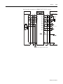
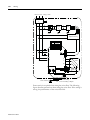
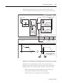
Electric Circuit Diagram
Power
MCCB (Molded Case Circuit Breaker)
MC (Magnetic Contactor)
1 MCCB
NOISE
FILTER
1 MC
1 MC
SW 1 OFF
SW 2 ON
Relay 1
<1>
<2>
<1>
For more than one second, press the
Push Button S/W which allows the
current to flow when pressed.
<2>
Connect this if the power needs to be
cut-off.
<3>
Attach a surge suppressor to the MC
relay coil.
SUP
<3>
Alarm Lamp
Relay 1
SERVO DRIVE
Servo Motor
1 MC
L1
U
L2
V
L3
Do not connect this to the
W
drive with less than 400 [W].
L1 C
L2 C
< Shield >
Motor Feedback
CN 2
PG
M
DCN
CN 1
I/O
Regenerative
Resistor
B1
45
SALM +
B2
1/ 2
+ 24V IN
46
SALM -
Heat Sink
CAUTION
5
Connect this to the
grounding terminal of the
Relay 1
24V
Use single-phase power in servo drive whose rated output
(capacity) is 400 [W] or lower. Thus, do not use the
terminal L3.
CSD5 Servo Drive
3-6
Wiring
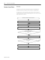
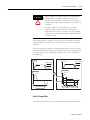
Using the Socket and Lever
This section describes the usage of wiring socket and lever provided
with servo drive.
• Connect only one wire at wire inlet of the socket.
• If the wire is pulled accidentally with an excessive force, rewire it
properly.
• The peeled wire can be used. (Keep the length of the peeled core wire
less than 8 [mm].)
• The use of phenol terminal is recommended for the reliability of wiring.
• Use a lever for wires provided with the product.
The following figure shows the sequence of assembling wire at the
socket.
1. As shown in the figure, insert lever in the socket and press it.
2. Insert wire into socket and release the lever.
3. Pull it slightly to check if the connection between the socket and wire is
normal.
Prepare the Wires
Strip of the
Phenol Terminial
Assemble the Socket
Wire
Terminal
+
Comress with the Phenol
Terminal Compressor
Socke
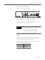
NOTE: Keep the length of the peeled wire less than 8
The thickness of wire allowed by the socket is shown below.
Thickness of Wire
Twist
CSD5 Servo Drive
AWG20 ~ AWG14
Lever
Wiring
CAUTION
NOTE
7
3-7
Insert the wire completely. If peeled core wire is exposed, it
may cause an electric shock.
The lever is a small tool, used when wiring. Keep it for
other wiring jobs.
CSD5 Servo Drive
3-8
Wiring
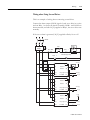
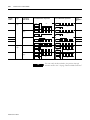
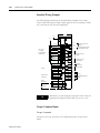
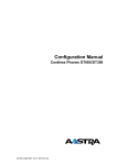
I/O Signal (I/O)
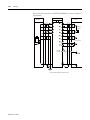
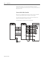
I/O Connection Diagram
This is the circuit diagram of a connector for I/O signal. It is divided
into input on the left and output on the right.
The Backup battery for absolute value encoder does not have the
separate terminal. It must be connected to motor encoder cable.
CN1
I/O
24V [or GND]
INPUT
OUTPUT
1
GND [or 24V]
2
37
INPUT1 (/SV-ON)(1)
(1)
INPUT2 (P-OT)
INPUT3 (N-OT)
(1)
INPUT4 (/P-CON)
24V
Active Low/High
Programmable
Digital Inputs
INPUT5 (/A-RST)
INPUT6 (/N-TL)
INPUT7 (/P-TL)
(1)
(1)
(1)
(1)
38
4
39
5
40
6
29
AM +
30
AM -
P
7
8
31
P
9
INPUT8
26
INPUT9
27
INPUT10
28
E-STOP
10
24V_PULS+
49
High Frequency
Position
Command
PULS +
11
PULS -
12
13
150
SIGN -
14
HF_PULS +
15
HF_PULS -
16
P
Speed Command
-10V to +10V
20
Current Command
-10V to +10V
22
21
41
P
CSD5 Servo Drive
42
43
P
P
16-bit
A/D
12-bit
A/D
50
Factory Default Value
46
44
47
19
(1)
18
45
SIGN +
24
P
150
2
23
36
17
2
25
HF_SIGN -
34
35
24V_SIGN+
HF_SIGN +
32
33
P
P
Position
Command
FAULT 1 / OUTPUT 4
3
48
Binary Fault Code Outputs
/ Digital Outputs
FAULT 2 / OUTPUT 5
FAULT 3 / OUTPUT 6
Binary Fault Code Ground
/ Digital Outputs Ground
FCOM/OUTCOM
BM +
BM -
Buffered
Encoder
Output
IM +
IM PS +
PS Z-PULSE +
Z-PULSE FAULT +
FAULT -
Absolute Position
Serial Output
Encoder
Marker
Pulse
Fault
Output
OUTPUT1+ (P_COM+)
OUTPUT1- (P_COM-)
OUTPUT2+ (TG_ON+)
OUTPUT2- (TG_ON-)
OUTPUT3+ (BK+)
OUTPUT3- (BK-)
24V
Programmable
Digital
Outputs
Wiring
3-9
Table 3.2 (I/O) Pin Arrangement for host controller connections
Pin
Symbol
Description
Pin
Symbol
Description
1
+24V IN
External 24 [V] input for contact point
input
26
INPUT8
Digital input 8
2
+24V IN
External 24 [V] input for contact point
input
27
INPUT9
Digital input 9
3
INPUT1
Digital input 1(/SV-ON)(1)
28
INPUT10
Digital input 10
4
INPUT2
Digital input 2(P-OT)(1)
29
AM+
Encoder signal output A+
5
INPUT3
Digital input 3(N-OT)(1)
30
AM-
Encoder signal output A-
6
INPUT4
Digital input 4(/P-CON)(1)
31
BM+
Encoder signal output B+
7
INPUT5
Digital input 5(/A-RST)(1)
32
BM-
Encoder signal output B-
8
INPUT6
Digital input 6(/N-TL)(1)
33
IM+
Encoder signal output Z+
9
INPUT7
Digital input 7(/P-TL)(1)
34
IM-
Encoder signal output Z-
10
ESTOP
ESTOP(Default:Disable)
35
PS+
Absolute Encoder Position data output+
11
PULS+
Position command pulse input+
36
PS-
Absolute Encoder Position data output-
12
PULS-
Position command pulse input-
37
FAULT1/
OUTPUT4
Alarm code output 1/Digital output 4
13
SIGN+
Position command sign input+
38
FAULT2/
OUTPUT5
Alarm code output 2/Digital output 5
14
SIGN-
Position command sign input-
39
FAULT3/
OUTPUT6
Alarm code output 3/Digital output 6
15
HF_PULS+
High frequency position command
pulse input+
40
FCOM/
OUTCOM
Alarm code/ Output ground
16
HF_PULS-
High frequency position command
pulse input-
41
OUTPUT1+
Digital output 1 +(P_COM+)(1)
17
Z-PULSE+
Encoder Z-pulse output (Open
collector)
42
OUTPUT1-
Digital output 1 -(P_COM-)(1)
18
Z-PULSE-
Encoder Z-pulse output (Open
collector)
43
OUTPUT2+
Digital output 2 +(TG_ON+)(1)
19
VCMD+
Speed command input+
44
OUTPUT2-
Digital output 2 -(TG_ON-)(1)
20
VCMD-
Speed command input-
45
FAULT+
Alarm generation signal output+
21
ICMD+
Current command input+
46
FAULT-
Alarm generation signal output-
22
ICMD-
Current command input-
47
OUTPUT3+
Digital output 3 +(BK+)(1)
23
HF_SIGN+
High speed position command sign
input+
48
OUTPUT3-
Digital output 3 -(BK-)(1)
24
HF_SIGN-
High speed position command sign
input-
49
24V_PULS+
Open collector pulse input + for 24 [V]
level
25
24V_SIGN+
Open collector sign input + for 24 [V]
level
50
NC
Not Available
(1)
9
Factory default values
CSD5 Servo Drive
3-10
Wiring
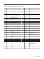
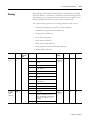
(I/O) Input Signal
Sequence Input Signal (Allocation)
Refer to the 5-1 page "Sequence I/O (Input/Output) Signal" for details
of sequence input signal.
Table 3.3
I/O Sequence Input Signal
Type
Description
Mode
Reference
</SV-ON> Servo-ON
When the servo is set to ON, voltage is applied to the servo
motor; when it is set to OFF, voltage is cut off.
All
4-1 page
</A-RST> Alarm Reset
It disables the Servo's Alarm.
All
7-49 page
</G-SEL> Gain Group
Conversion
Use 2-group gain where it is set to ON and use current gain
where it is set to OFF. It converts gain of 2 groups.
All
6-36 page
</P-CL> Forward Torque
Limit
When it is set to ON, limit the forward torque by the set value
[Ft-4.03].
All
5-46 page
</N-CL> Reverse Torque
Limit
When it is set to ON, limit the reverse torque by the set value
[Ft-4.04].
All
5-46 page
<P-OT> Prohibit Forward
Rotation
It prohibits the motor from rotating forward when the load
device reaches the limit of the available section.
All
7-2 page
<N-OT> Prohibit Reverse
Rotation
It prohibits the motor from rotating reversely when the load
device reaches the limit of the available section.
All
7-2 page
</P-CON> P Control
Conversion
It converts the Seed Controller from PI type controller to P
type controller. It is used to suppress the overshoot of the
excessive response and complete a faster response.
F, S, P, I
6-30 page
</C-SEL> Control Mode
Conversion
It is used to convert Control Mode when using it as
Combination Control Mode.
Combinational
Control Mode
Only
5-57 page
</C-DIR>
</C-SP1>
</C-SP2>
</C-SP3>
</C-SP4>
Contact Speed Command
At the Contact Speed Control Mode, these input combinations
decide the rotation direction of the motor </C-DIR> and the
rotation speed </C-SP1 ~ /C-SP4>. The rotation speed for </
C-SP1~/C-SP3> input is set in [Ft-2.05~Ft-2.11]. The
analogue speed command voltage decides the rotation speed
for </C-SP4>. </C-DIR> is used to change the motor rotation
direction in Speed Control Mode.
P
5-51 page
</Z-CLP> Zero Clamp
Ignores the input value in the Speed Control when the
command value is lower than the value set in the Speed Zero
Clamp Level [Ft-5.05].
S
5-35 page
</INHIB> Inhibit Pulse
Command
Inhibits the position command pulse where it is ON.
F
5-25 page
</ABS-DT> Absolute
Encoder Data Transmission
When it is set to ON, transmits the absolute encoder data to a
higher level through AM, BM signals.
F, I
7-50 page
</PCLR>Position Error Clear
Clears position command, position feedback, and position
error.
F, I
</START>Start
Set to start or stop the motor rotation by using the contact
signal in Speed/Contact Speed Control Mode.
S, P
</GEAR>Electronic Gear
Rate Shift
In the Position Control Mode, use the 2nd electronic gear
parameter [<:fc 2>Ft<:/fc>-3.05]and [Ft-3.06] where it is ON,
use the basic electronic gear parameter [Ft-3.01]and [Ft-3.02]
where it is OFF. It shifts between two electronic gear ratios.
F
</R-ABS>Absolute Encoder
Multi-rotation Data Reset
Reset the multi-rotation data of the absolute motor.
All
CSD5 Servo Drive
5-25 page
5-37 page
5-27 page
7-34 page
Wiring
Table 3.3
3-11
I/O Sequence Input Signal
Type
Description
Mode
Reference
</BANK_SEL>Gain Bank
Select
Uses the 3rd and the 4th Gain Bank when it is set to ON.
All
6-38 page
</A-CL>Analog Torque Limit Current Limit Function is activated by the analogue torque
command input values when it is set to ON.
S, P
</H_SENS>Home Sensor
When activated, the sensor indicates the Return to Home
sequence that is detected.
I
</SHOME>Start Homing
When activated, the system starts returning to home.
I
.
</PAUSE>Index Pause
When activated, it decelerates until stop and pause the index
sequence. It decides whether to stop or to continue the motion
by constantly monitoring the input status.
I
.
</STOP>Index Stop
When activated, index movement ends.
I
.
</I-SEL0>
Index Selection 0 Input
</I-SEL1>
Index Selection 1 Input
</I-SEL2>
Index Selection 2 Input
</I-SEL3>
Index Selection 3 Input
</I-SEL4>
Index Selection 4 Input
</I-SEL5>
Index Selection 5 Input
Used for the combinations to allocate indexes.
I
.
</H_STOP>Homing Stop
Stops Homing operation when it is set to ON.
I
</START_I>Start Indexing
Starts Indexing when it is set to ON.
I
</ABS-MD> Absolute
Position Data Transfer Mode
Absolute Data transfered to host contoller by photo coupler
output which output Fault Code when it is set to ON.
F
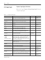
General Input Signal (Fixed)
Power
Table 3.4
Power Input Signal
Signal Name
Symbol
Function
Mode
External power
input
+24V IN
As control power input for contact point signal, +24 [V]
power should be prepared by users.
All
Reference
Power Specifications: 21.6 ~ 26.4V, 210mA
11
CSD5 Servo Drive
3-12
Wiring
Emergency Stop
Table 3.5
Emergency Stop Input Signal
Signal Name
Symbol
Function
Mode
Reference
Emergency Stop
E-STOP
Connect and use an extra emergency stop switch to
quickly act upon emergency situation, users can select
whether to use in [Ft-0.05] constant.
All
3-18 page
Position Command
Table 3.6
Position command input signal
Signal Name
Symbol
Function
Mode
Reference
Pulse Command
PULS+
Receives position command by pulse input. Can
respond to line drive or 12 [V] & 5 [V] open collector
output of the host controller.
F
5-10 page
Connect the high frequency pulse input to this terminal.
(Line Drive less than 3 [Mpps])
F
For Open Collector 24 [V] pulse input, connect to this
terminal without a pull-up resistance.
F
Receives analog speed command.
(-10 [V] ~ +10 [V])
S
5-32 page
Receives analog torque command.
(-10 [V] ~ +10 [V])
C
5-43 page
PULSSIGN+
SIGNHigh Frequency
Pulse Command
HF_PULSE+
HF_PULSEHF_SIGN+
HF_SIGN-
Open Collector(24
[V]) Pulse
Command
24V_PULSE+
PULS24V_SIGN+
SIGN-
Speed Command
Input
VCMD+
Torque Command
Input
ICMD+
CSD5 Servo Drive
VCMD-
ICMD-
Wiring
3-13
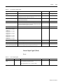
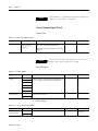
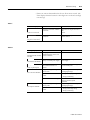
Sequence Output Signal (Allocation)
(I/O) Output Signal
Refer to the 5-1 page "Sequence I/O (Input/Output) Signal" for details
of sequence output signal.
Table 3.7
I/O Sequence Output Signal
Signal Name
Description
Mode
Reference
</S_ALM> Alarm
Outputs when Servo Alarm sets off.
All
8-5 page
</P-COM (+, -)> Position
Completion Detection
Turns to ON, when the position error is within the set value of
the position completion range [Ft-5.00].
F, I
5-28 page
</NEAR (+, -)> Position
Proximity Detection
Turns to ON, when the position error is within the set value of
the position completion range [Ft-5.02].
F, I
5-28 page
</V-COM (+, -)> Speed
Match Detection
Turns to ON when the deviation between the speed command
and the motor rotation speed is within the set value of the
speed match decision range [Ft-5.03].
F, S, P, I
5-38 page
</TG-ON (+, -)> Rotation
Detection
Turns to ON when the motor is rotating above the set value of
the rotation detection level [Ft-5.04].
All
5-39 page
</T-LMT (+, -)> Torque Limit
Detection
Turns to ON when torque reaches the set value of the torque
limit.
All
5-46 page
</V-LMT (+, -)> Speed Limit
Detection
Turns to ON when speed reaches the set value of the speed
limit.
All
5-41 page
<BK (+, -)> Brake Control
It is the signal for the brake control installed inside or outside
of the servo motor.
All
7-6 page
</A-VLD> Absolute Position
Valid
Turns to ON when the absolute position data is valid while
using the absolute motor.
All
</RDY> Drive Ready
Means getting the operation ready while in the Servo-OFF
status.
All
</WARN (+, -)> Warning
Turns to ON when a Servo warning is detected.
All
8-3 page
</HOMC (+,-)> Axis Homing When activated, it shows the completion of the Homing
operation.
I
.
</IMO (+,-)> In Motion
Turns to ON when in motion.
I
.
</I-DW> In Dwell
When activated, it indicates that the motor is on the hold
position in the index movement and on stand-by for the dwell
time assigned.
I
.
</O_ISEL0>
Index Selection 0 Input
</O_ISEL1>
Index Selection 1 Input
</O_ISEL2>
Index Selection 2 Input
</O_ISEL3>
Index Selection 3 Input
</O_ISEL4>
Index Selection 4 Input
</O_ISEL5>
Index Selection 5 Input
Used to output the index number in use in the selected
indexing operation.
I
.
</E_SEQU> Sequence
Operation Completion
Turns to ON when the index movement is complete.
I
13
CSD5 Servo Drive
3-14
Wiring
NOTE
In this manual, < > is applied to the names of sequence I/
O signal. ex) </SV-ON>, </P-COM>
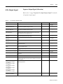
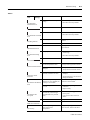
General Output Signal (Fixed)
Alarm Code
Table 3.8 Alarm Code Output Signal
Signal Name
Symbol
Function
Mode
Reference
Alarm code
FAULT1/OUTPUT4
(Alarm 1/Digital
output 4)
Upon servo alarm generation, it outputs the
types of the servo alarm with the 3-bit.
All
8-3 page
Maximum rating of open collector: DC 30 [V],
20 [mA]
NOTE
If one or more of Alarm code (FAULT1, 2, and 3) set to
Digital output, Alarm code does not output.
Encoder Signal
Table 3.9
Encoder Signal
Signal Name
Symbol
Function
Mode
Reference
Encoder Signal
Output
AM+
Displays multiplied encoder signal A, B, C pulse in the
form of line drive. According to the parameter setting,
the drive can logically invert output of A, B pulse.
All
7-24 page
Outputs the number of rotation by serial data when the
absolute encoder is used.
All
7-24 page
AMBM+
BMIM+
IM-
Absolute Encoder
Position S pulse
PS+
PS-
Servo Alarm
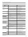
Table 3.10
Servo Alarm Output Signal
Signal Name
Symbol
Function
Mode
Reference
Servo alarm
Monitor Output
FAULT+
It is displayed if the servo alarm is generated.
All
7-28 page
CSD5 Servo Drive
FAULT-
Wiring
3-15
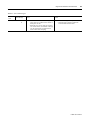
Encoder Z-pulse Display
Table 3.11
Encoder Z-pulse Output Signal
Signal Name
Symbol
Function
Mode
Encoder Z-pulse
Z-PULSE +
It is displayed if Z-Pulse of the encoder is detected.
All
Reference
Z-PULSE -
15
CSD5 Servo Drive
3-16
Wiring
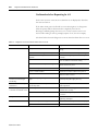
(I/O) Input Circuit and
Interface
Describes the connection circuit for input from the host controller to
the servo drive.
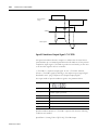
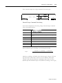
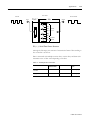
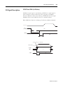
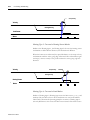
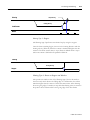
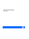
Pulse Command Input Circuit
The drive receives the pulse output of host controller by position
command in position control mode.
Host controller can output pulse in line drive or open collector type.
Refer to the 5-10 page "Position Control Mode" for the servo drive
setting according to the selection.
Line drive - Maximum allowable frequency 900 [kpps](Duty ratio: 50:50)
– Input pin number
• PULS+ (11), PULS- (12)
• SIGN+ (13), SIGN- (14)
Line Drive
150 [ Ω ]
1 [k Ω ]
SN75174
P
2.8 [V] ≤ (H Level) - (L Level) ≤
Host
I/O
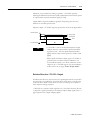
Open Collector (24 [V])- Maximum Allowable Frequency 250 [kpps]
– Input pin number
• 24V : PULS+ (49) , PULS- (12)
• 24V : SIGN+ (25), SIGN- (14)
Open Collector
Vcc
2
i
P
TR1
1
VF
VF = 1.5 ~ 1.8
I/O
Host Controller
NOTE
For Open Collector 24 [V] input, it does not need the
external resistance.
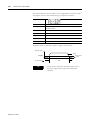
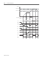
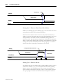
High Frequency Line Drive - Maximum Allowable Frequency 3 [Mpps]
– Input pin number
CSD5 Servo Drive
Wiring
3-17
• PULS+ (15), PULS- (16)
• SIGN+ (23), SIGN- (24)
Line Drive
SN75174
P
I/O
Host
Maximum allowable frequency of host controller’s pulse
command is
NOTE
• 900 [kpps] for the line drive
• 3 [Mpps] for high speed line drive
• 250 [kpps] for the open collector
If the maximum allowable frequency is exceeded,
[E.PoSEr] servo alarm of position command pulse is
generated. Make sure the output of host controller does not
exceed the maximum allowable frequency.
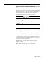
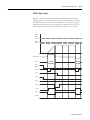
Analog Voltage Input Circuit
The drive receives analog voltage output of the host controller with
speed, speed of torque control mode and torque command.
Input impedance of speed and torque commands is about 10 [kΩ].
Maximum allowable voltage range of input signal is -10 [V] to +10 [V].
Input pin of I/O that uses analog voltage output of the host controller:
• Speed Command: VCMD+ (19), VCMD- (20)
• Torque Command: ICMD+ (21), ICMD- (22)
Analog Input Circuit
Speed
390 [ Ω ] (1/2
VCMD+
12 [V]
2
1000:1
Host
17
P
VCMD-
+
A/D
I/O
0 [V]
CSD5 Servo Drive
3-18
Wiring
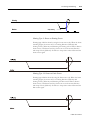
Analog Input Circuit
Torque
390 [ Ω ] (1/2
ICMD+
12 [V]
2
1000:1
P
+
A/D
ICMD-
I/O
0 [V]
Host
Sequence Input Circuit
Relay or open collector output of the host controller is used for the
sequence input circuit.
Make sure that the input current i is within 7 [mA] to 15 [mA].
Relay Circuit
i
DC 24 [V] 50 [mA] or
+24 [V]
3.3 [k Ω ]
P
I/O
Sequence Input
Signal
Host
Open Colletor Circuit
i
DC 24 [V] 50 [mA] or
Host
+24 [V]
3.3 [k Ω ]
P
Sequence Input
Signal
I/O
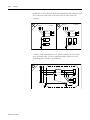
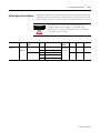
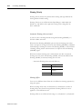
Emergency Stop Signal
This drive has a built-in circuit for the emergency stop situation.
To quickly respond to the equipment failure or dangerous situation, it
receives the emergency stop signal from #10 pin of I/O.
Emergency stop input can be done by the relay contact output of host
controller and installing a separate switch.
CSD5 Servo Drive
Wiring
3-19
Whether to use the emergency stop input can be set by the parameter
[Ft-0.05]; the initial value is set as not to use.
#10 pin of I/O assigned below is used as the input pin only for the
emergency stop.
Normal
External Power 24 [V]
+24 [V]
1/2
E-STOP
10
+24 [V]
1/2
E-STOP
10
E-STOP Switch
E-Stop
E-STOP Switch
Install a host
Controller or a
NOTE
19
External Power 24
I/O
• If the emergency stop signal is input, [E.EStoP] servo
alarm is generated.
• Refer to the 8-3 page "Protection Function" more
information on the servo alarm.
• If the emergency stop is released, reset the alarm by
referring to the 7-49 page "Alarm Reset (run-08)".
• You can check the status of emergency stop signal
through the monitor mode describe in the 7-52 page
"Monitor Mode Function".
CSD5 Servo Drive
3-20
Wiring
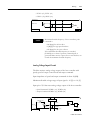
(I/O) Output Circuit and
Interface
There are 2 types for the servo drive output circuits. Design the input
circuit at the host controller suitable for the each output circuit.
• Line Drive Output
• Photo-Coupler output
Line Drive Output
Output signal (AM+, AM-, BM+, BM-) that converted the encoder
serial data into 2 phase (A phase and B phase) pulse, zero point pulse
signal (IM+, IM-) and S phase rotation amount signal (PS+, PS-), are
output to line drive circuit. It is used to configure the position control
loop from the host controller. Receive the pulse signal with the line
receiver circuit in the host controller.
Set R1 value to 330 [Ω].
R1
P
I/O
0 [V]
Host
Photo-Coupler Output
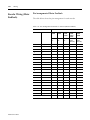
Servo alarm, sequence output signal and encoder Z-pulse signal output are the
photo coupler output circuits.
Connect to the photo-coupler circuit of the host controller:
DC 5~12 [V]
Photo-Coupler
P
0 [V]
I/O
CSD5 Servo Drive
0 [V]
Host
Wiring
3-21
Connect to the relay circuit of the host controller:
DC 5~24 [V]
Relay
P
0 [V]
I/O
Host
Connect to the line receiver circuit of the host controller:
DC 5~12 [V]
Line Receiver
P
I/O
21
0 [V]
Host
CSD5 Servo Drive
3-22
Wiring
Encoder Wiring (Motor
Feedback)
Pin Arrangement of Motor Feedback
The table below shows the pin arrangement for each encoder.
Table 3.12 Pin Arrangement for Encoder C onnector (Motor Feedback)
Drive
No.
Function
CSMT
CSMR
RSMQ
RSMZ
RSMS
RSMD
RSMH
CSMT
CSMR
RSMQ
RSMZ
RSMS
RSMD
RSMH
9 wire
Inc.
9 wire
Inc.
9 wire
Inc.
17-bit
17-bit
Serial
Serial
(Abs, Inc) (Abs, Inc)
1
EO [V]
8
11
G
8
G
2
-
-
-
-
-
-
3
A
1
1
A
-
-
4
/A
2
2
B
-
-
5
B
3
3
C
-
-
6
/B
4
4
D
-
-
7
C
5
5
E
-
-
8
/C
6
6
F
-
-
9
LMT-
-
-
-
-
-
10
S1/SD+
-
-
-
4
K
11
-
-
-
-
-
-
12
-
-
-
-
-
-
13
SD-
-
-
-
5
L
14
S2
-
-
-
-
-
15
-
-
-
-
-
-
16
S3
-
-
-
-
-
17
LMT+
-
-
-
-
-
18
-
-
-
-
-
-
19
-
-
-
-
-
-
20
E5 [V]
7
10
H
7
H
9
12
J
3
J
FG
CSD5 Servo Drive
Motors
Wiring
3-23
Terminal Type
The table below shows the terminal type and specifications of the
encoder cable.
Encoder Cable
CON A.
(Connect this to
Moter Feedback )
CON B.
Connect this to the
encoder cable of the
1 PIN 2 PIN
Connector CON A for connection to Motor Feedback of servo drive:
One type regardless of motor model and encoder.
Model Number
Manufacturer
10120-3000PE
10320-52F0-008(LATCH)
10320-52A0-008(SCREW)
3M
Connector CON B for connection to the encoder cable of servo motor:
Motor
Type
Housing
Terminal
Manufacturer
CSMT, CSMR
9 wire Inc.
Serial Absolute
Serial Inc.
172161-1
170361-1
or
70365-1
AMP
RSMZ, RSMQ
9 wire Inc.
171162-1
RSMS, RSMD,
RSMH, RSMF, RSMK,
RSML
9 wire Inc.
DMS 3108B20-29S or DMS 3106B 20-29S
DDK
Power cable connector for large capacity motor packed with the motor.
NOTE
23
Do not connect FG of servo drive to host controller if
GND and FG are common, or if there is no separate FG.
CSD5 Servo Drive
3-24
Wiring
Encoder Signal Process
Incremental encoder (9 wire Inc.) connection of CSMT/R motors.
Encoder
Servo Drive
Motor
Host
I/O
Incremental encoder (9 wire Inc.) connection of RSMS/D/F/H/K/L
motors.
Encoder
Servo Drive
Motor
CSD5 Servo Drive
I/O
Host
Wiring
3-25
Serial encoder connection of RSMS/D/F/H/K/L motors.
Encoder
Servo Drive
Motor
Host
I/O
Serial I/F Circuit
Up/Down
Counter
Serial I/F Circuit
* Connect when absolute encoder is used
25
CSD5 Servo Drive
3-26
Wiring
Serial encoder connection of CSMT/R, RSMKQ/Z motors (Absolute,
Incremental).
Encoder
Servo Drive
Motor
Host
I/O
Serial I/F Circuit
Up/Down
Counter
Serial I/F Circuit
* Connect when absolute encoder is used
CSD5 Servo Drive
Wiring
General Articles Wiring
3-27
This part describes wiring to implement optimum performance of the
servo drive in wiring and noise.
Precautions
Electric Circuit
• Use a thick wire as earth wire if possible.
• Class 3 grounding is recommended. (Recommendation: grounding
resistance lower than 100 [ Ω ])
• Only 1 point must be grounded.
• Select ground phase and ground point considering the power conditions
of installation area. If the power is supplied by the ground phase, wire it
so that L2 of AC main power input terminal (L1, L2, and L3) becomes
the ground phase.
• Use noise filter for the main power and control power.
• Electric circuit wiring and signal circuit wiring should be apart as much
as possible. (30 [cm] or more)
• Do not use same power with the electric ARC welding machine or
discharge processor equipment.
• The earth wire of the servo motor must be connected to the grounding
terminal of the drive. In addition, ground the grounding terminal of the
drive.
• If the wiring is inside the metal pipe, ground the pipe with class 1
grounding.
Signal Circuit
• The host controller should be installed as closely as possible to the drive,
and the noise filter must be used.
• I/O (I/O signal connector) and Motor Feedback (encoder cable) should
be twist pair wire and batch shield wire.
• Note that the signal circuit wire is very thin, thus pay attention when
handling it.
• If the noise is generated at command input cable, ground 0 [V] line (SG)
of the input line before the usage.
27
CSD5 Servo Drive
3-28
Wiring
NOTE
Refer to the servo motor manual more information on the
following cable Specifications and order code.
• Motor 3 phase power cable
• Encoder cable
• Motor brake cable
• I/O cable
• Communication cable
Others
• Use the breaker or fuse for wiring to protect the servo drive.
• Make sure there is no continuous bending and stress to the wire.
• Use noise filter in radio noise.
• If used around residential area or the radio disturbance is concerned,
install a noise filter on the input side of power line.
• As the drive is for industrial use, there are no measures for radio
disturbance.
• Attach a surge absorption circuit to the relay, solenoid, and coil of the
magnetic contactor.
Capacity of the Drive and Fuse
The table below shows the capacity of servo drive and fuse.
Table 3.13 Fuse Specifications
Drive
Capacity
Power Capacity per
1 Drive [kVA]
MCCB or Fuse Power
Capacity [Amps]
CSD5_A5BX1
50 W
0.25
4
CSD5_01BX1
100 W
0.40
4
CSD5_02BX1
200 W
0.75
4
CSD5_04BX1
400 W
1.2
8
CSD5_08BX1
800 W
2.3
8
CSD5_10BX1
1 kW
2.3
8
CSD5_15BX1
1.5 kW
3.2
10
The fuse capacity is the value when 100 [%] load is applied. When
selecting the MCCB (breaker for wiring) or fuse capacity, select the fuse
capacity considering the load ratio.
CSD5 Servo Drive
Wiring
3-29
Cut-off features: 200 [%]- 2 seconds or more. 700 [%] - 0.01 second or
more.
CAUTION
The high -speed cut-off fuse cannot be used. As the power
of the drive is condenser input type, the fuse may be blown
even during a normal situation if the high-speed cut-off
fuse is used.
Noise Protection
The high-speed switching device and microprocessor are used at the
main circuit of the servo drive. Thus, switching noise is affected by the
connection and grounding methods. Use the proper wiring and
grounding method to prevent any affects from the noise.
CAUTION
29
Use a wire of 3.5 [mm2] or thicker for the earth wire.
Separate the signal and power wiring.
CSD5 Servo Drive
3-30
Wiring
3 Phase AC 200 ~ 240 [V] <50/60
LINE FILTER
1
P
P
LINE
FILTER
2
P
AVR
Ralay Sequence Circuit
Signal Generating
Servo Drive
L1
L2
I/O 1
CN
L3
L1C
U
Servo
Motor
L2C
V
W
Heat Sink
Motor Feedback
CN 2
PG
M
Ground Plate
Earth Grounding
One Point Grounding
<Class 3 Grounding or Higher>
Extra caution is required when wiring the noise filter. The following
figure describes precautions when wiring the noise filter. If the wiring is
wrong, the performance of the noise filter falls.
CSD5 Servo Drive
Wiring
3-31
Separate the input and output wiring of the noise filter and do not tie up
them together.
Primary and
Secondary
Interference
FILTER
Primar Secondar
FILTER
Primar Secondar
Primary and
Secondary
Interference
Primary
Secondary
Secondary
Primary
FILTER
FILTER
Primar Secondar
Primar Secondar
Separation of
Separation of
Earth wire of the noise filter should be wired in distance to the output
wire and do not put other signal lines and earth wire in a same duct and
tie up them together.
Primary
Secondary
FILTER
Primar Secondar
31
Primary
Secondary
FILTER
Primar Secondar
CSD5 Servo Drive
3-32
Wiring
Earth wire of noise filter should be solely attached in the earth plate. Do
not connect the earth wire of the noise filter to other earth wire
together.
Primary
Primary
Secondary
FILTER
Secondary
FILTER
Primar Secondar
Primar Secondar
If there is noise filter inside the case (panel), connect all of the earth
wires and earth wires of other equipment inside of the case to the
grounding plate. And then, ground them.
FILTER
Primar Secondar
CSD5 Servo Drive
Wiring
3-33
Wiring when Using Several Drives
This is an example of wiring when connecting several drives.
Connect the alarm output (SALM) signal of each servo drive in a series
and run Relay 1 to detect the alarm. Normally, SALM+ and SALM- are
interconnected, and with 24 [V] supplied to Relay1, the servo drive runs
normally.
If the servo alarm is generated, 24 [V] supplied to Relay1 is cut off.
1 MCCB
NOISE
FILTER
1 MC
1 MC
SW 1 OFF
SW 2 ON
Relay
1
Relay
1
SUP
Alarm Display Lamp
1 MC
+ 24 [ V ]
I/O 1
CN
L1
L2
L3
FAULT +
45
FAULT -
46
L1C
+ 24 [ V] IN 1 / 2
L2C
E- STOP
L3
FAULT +
45
FAULT -
46
+ 24 [ V] IN 1 / 2
L2C
E- STOP
L1
L3
L1C
L2C
33
+ 24 [ V ]
0 [ V]
10
L1C
L2
Referenc
1
I/O 1
CN
L1
L2
Relay
Referenc
0 [ V]
10
I/O1
CN
FAULT +
45
FAULT -
46
+ 24 [ V] IN 1 / 2
E- STOP
10
+ 24 [ V ]
0 [ V]
+ 24 [ V ]
Reference
0 [ V]
CSD5 Servo Drive
3-34
Wiring
NOTE
Whether to use the emergency stop input can be set by the
parameter [Ft-0.05]; the initial value is set as not to use. Do
not wiring when it does not using the emergency stop.
Connection to Peripheral Equipment
AC 220 [V] Power
R S T
MCCB
Breaks the circuit if large
inruch current flows on
power line.
Noise Filter
Remove the noise from
the power line.
Magnetic Contactor
Renerative Resistor
RS-232/
RS485
I/O
Host
Magnetic
Contactor for the
Motor Break
Contorl
Motor Cable
Break Cable
Motor Break
Control Power
Motor Break Control
Servo Motor
CSD5 Servo Drive
Motor Feedback
Encoder Cable
Chapter 4
Operator, Basic Setting and Startup
This chapter introduces the operator mounted on the servo drive. In addition,
it describes the basic setting of servo drive, and also an example for simple
startup.
Before You Begin
About Servo-ON Signal
This part describes Servo-ON signal for the control of the servo drive.
What is Servo-ON?
Audio or TV can select and play music and display channel that the users want
from the moment the power switch is on.
However, the servo drive cannot run servo motor by simple applying the
power. To complete load the system and use the servo drive, Servo-ON signal
from the host controller is required.
Servo-ON signal should be applied and maintained from the host controller
for the servo drive to run the motor. In servo -OFF status, it cannot run the
motor.
1
CSD5 Servo Drive
4-2
Operator, Basic Setting and Startup
Servo-OFF and Servo-ON
Table 4.1
Servo-OFF and Servo-ON
Servo-OFF Status
Servo-ON Status
Input of commands such as position, speed
regarding servo-ON status and motor run
• If the servo-ON signal is not
applied after the power
application, it is same as the
servo driver and motor being
separated completely.
• This is a ready status to run the
motor.
• If the servo-ON signal is applied from the
host controller, the drive starts to apply
voltage to the motor. At this time, if there
is no motor run command, the drive
maintains the motor stopped.
• If the motor run command is input while the
servo-ON signal of the host controller is
maintained, the drive can run the motor according
to the command.
Powe
Powe
Powe
/SV-ON
Input of command
like position, speed
/SV-ON
Motor
Roation
Servo-ON Signal of the Host Controller and Running the Automobile
The following describes the servo drive in relation to the transmission of the
automobile.
Host
Driver
Apply power to
the drive
Receive
servo-On signal
Start automobile
Set transmission
at position D.
Receive command such
as position, speed
Run
accelerator
Motor
rotate
Automobil
e runs
As the transmission of the automobile should be positioned at 'D' to start the
automobile, the drive can be run only when the servo-ON of the host
controller is maintained.
Commands to run the motor such as the position, speed of host controller are
invalid in Servo-OFF status.
CSD5 Servo Drive
Operator, Basic Setting and Startup
4-3
Servo-ON/OFF Signal Indication
In this manual, the Servo-ON signal is indicated as shown below.
Servo-ON, </SV-ON>
Servo-OFF
Servo-ON Signal Input
Servo-ON signal from host controller is received through the sequence input
signal of I/O. Refer to the 5-1 page "Sequence I/O (Input/Output) Signal" for
the sequence I/O signals.
Servo Drive's Own Servo-ON
If the servo drive runs the motor without a command from the host controller
as in the operation mode (run-00), (run-01), the drive makes itself Servo-ON
for the operation.
TIP
• Refer to the 7-41 page "Operation Mode Function" for
the operation mode (run-00) to (run-02). In addition,
the operation mode (run-00) is described in the 4-21
page "Startup" Startup.
• (run-00), (run-01), (run-07), (run-08), (run-10), (run-12)
are not operated in Servo-ON status.
Alarm Occurrence and Servo-ON Status
If servo alarm is occurred by the self-diagnosis function of the drive while the
Servo-ON signal is applied to the drive, the drive make itself Servo-OFF to
stop the motor and displays the contents of servo alarm. Users should inspect
the contents of servo alarm, take necessary action, and reset the alarm (Refer
to the7-49 page "Alarm Reset (run-08)". At this time, if an appropriate action
against the servo alarm is taken and the servo-ON signal of host controller is
maintained, the drive returns to servo-ON status at the moment that alarm is
reset.
Refer to the 8-3 page "Servo Warning" for the information of the servo alarm.
TIP
3
• All parameter setting after Chapter 4 should be done
for the Servo-ON status and Servo-OFF status.
• In this manual, ‘the servo drive status’ means whether
the servo drive is in servo-ON status or servo-OFF
status.
CSD5 Servo Drive
4-4
Operator, Basic Setting and Startup
Operator
Name and Function of Each Part
The servo drive has a built-in operator for various status displays, parameter
setting, operation command, and monitoring.
• Displays various contents with six 7-segment LED display.
• Provides all key manipulation function without a separate external
operator.
The following figure shows the front side of the operator on the servo drive.
1
2
4
3
Table 4.2
Name and Function of Each Part
No.
Name
Function
1
7-Segment LED Display
Displays the status with 6-digit 7-segment LED display, sets parameter, commands operation
and displays monitoring.
2
MODE/SET Key
Enters display mode shift and parameter setting value.
3
ENTER Key
Enters into each window after changes the display mode. Completes setting and exits from it.
4
Top, Bottom, Left/Right Key
Moves the digit of 7-segment LED display and functions as the UP/DOWN of the number.
Icons for the Key Buttons
Icon is used in description throughout the manual. Thus, be fully aware of the
shape, name and function of icons.
CSD5 Servo Drive
Operator, Basic Setting and Startup
Table 4.3
4-5
Icons for the Key Buttons
Key Button(1)
Name
Function
Up
• Increases and decreases the value
• Press and hold this icon to continuously
increase/decrease the value
Down
Left
• Shifts the digits
Right
Direction
Key
• Used to indicate up, down, left, right keys
altogether
MODE/ SET
Key
• Changes the mode
• Saves the setting value
• Start running
ENTER Key
• To enter/exit each setting window after
changing the mode
• Select setting value
(1)
Black key button represents that it is pressed.
Structure of the Entire Mode
As shown in the figure below, the servo drive is divided into 5 types of control
modes:
The mode displayed after the power ON is the status display mode. Mode is
changed whenever the MODE/SET key is pressed. Be fully aware of the
following 5 mode types and read the following.
5
CSD5 Servo Drive
4-6
Operator, Basic Setting and Startup
Power Connection
Status Display
Parameter Setting Mode
Operation Mode
Index Mode
Monitor Mode
The displayed values in the above figure are the initial value of each mode.
If the value is changed in a mode and then returned, the changed value is
shown instead of the initial value.
CSD5 Servo Drive
Operator, Basic Setting and Startup
4-7
Status Display Mode
This section describes contents of the status display mode.
The figure below is an example of display for the description of the status
mode. Refer to the table below for the meaning of each display.
Row Display
Control
Point
Status
Row Display Row Display
Control Mode (Ft-0.00)
Displays control mode in use. In Servo-ON status (in operation), the display of
the control mode flickers.
Table 4.4
Status Display Modes - Control Mode
Display
Basic Control
Mode
Description
Position mode
Speed mode
Torque mode
Multi-step speed mode
Index mode
Combinational
Control Mode
Speed + position mode
Torque + speed mode
Torque + position mode
Multi-step speed + position mode
Multi-step speed + speed mode
Multi-step speed + torque mode
7
CSD5 Servo Drive
4-8
Operator, Basic Setting and Startup
In combinational control mode, it performs two types of selected mode
simultaneously for the operation. And at this time, the display of the current
mode is flickered. If the mode is changed, the display of new mode flickers,
and the previous mode does not.
Status
Displays corresponding character upon servo warning.
Refer to the 8-3 page "Servo Warning" for details of the servo warning.
Table 4.5
Status Display Mode - Status
Display
Description
It means the preparation for the operation in
Servo-OFF status.
Displays that it is running.
Displayed when forward operation prohibiting signal
is input.
Displayed when reverse operation prohibiting signal is
input.
Point Display
It is on if the power is applied.
Row Display
Refer to the reference pages on the right for more information on the row
display.
Table 4.6
Status Display Mode -Row Display
Row Display 1
Row Display 2
Row Display 3
Description
Reference
When using as a position mode, if the difference between load position and position command is
smaller than [Ft-5.00] value, the servo drive can display (</P-COM> position completion detection)
signal. It is on when </P-COM> signal is displayed.
page 5-28
When using as a speed mode, if the difference between motor speed and speed command is smaller
than [Ft-5.03] value, the servo drive can display (</V-COM> speed coincidence detection) signal. It
is on when </V-COM> signal is displayed.
page 5-38
When the rotation speed of the motor is higher than the setting value of rotation detection level
[Ft-5.04], the servo drive can display (</TG-ON> rotation detection) signal. It is on when </ TG-ON
> signal is displayed.
It is on when Z-pulse output of the encoder is detected. In case of linear motor, it is on when first hall
U signal is detected
CSD5 Servo Drive
page 5-39
Operator, Basic Setting and Startup
4-9
Overview of the Parameter Setting Mode
This section includes brief explanation of the parameters in parameter setting
mode.
The Parameter sets and saves various functions to make drive suitable for
equipment.
There is a parameter that can be always set regardless of the status of the drive,
and those that must be in certain status of the drive when setting them. Be
careful to set parameter in reference to the contents in the Appendix B "Table
for Parameter Setting".
The contents related to parameter setting are described in details in Chapter
#5, 6, 7, 8 and the Appendix along with the functional description of the servo
drive.
The table below is to aid the understanding of parameter group.
Parameter range:
From
Table 4.7
To
Parameter Group
Parameter Group
9
Parameter Group Description
Group 0
Ft-0.00 ~ Ft-0.32
33
User parameter related to basic setting and
I/O signal
Group 1
Ft-1.00 ~ Ft-1.42
43
User parameter related to gain and gain
tuning
Group 2
Ft-2.00 ~ Ft-2.13
14
User parameter related to speed control
mode
Group 3
Ft-3.00 ~ Ft-3.08
9
User parameter related to position control
mode
Group 4
Ft-4.00 ~ Ft-4.06
7
User parameter related to torque control
mode
Group 5
Ft-5.00 ~ Ft-5.16
17
User parameter related to supplementary
function
CSD5 Servo Drive
4-10
Operator, Basic Setting and Startup
Overview of the Monitor Mode
This section includes brief explanation of the parameters in monitor mode.
Displays several numerical data generated as the motor is controlled by the
drive. The contents of the monitor mode can be checked regardless of the
status of the drive. Be fully aware of the numbers and units displayed in
monitor mode shown in the table below and refer to it when using the servo
drive.
The table below shows the brief contents of each item in the monitor mode.
Monitor Mode Range:
From
Table 4.8
CSD5 Servo Drive
To
Monitor Mode
Item
Monitor Contents [Unit]
dIS-00
Speed feedback [rpm or mm/sec]
dIS-01
Speed command [rpm or mm/sec]
dIS-02
Speed error [rpm or mm/sec]
dIS-03
Torque command [%]
dIS-04
Position feedback [pulse]
dIS-05
Position command [pulse]
dIS-06
Position error [pulse]
dIS-07
Position command pulse frequency [kpps]
dIS-08
Electrical angle [ °]
dIS-09
Mechanical angle [ °]
dIS-10
Accumulated load rate of regenerative resistor [%]
dIS-11
DC Link voltage [V]
dIS-12
The number of rotation data of absolute encoder
dIS-13
Speed command offset [mV]
dIS-14
Torque command offset [mV]
dIS-15
I/O status
dIS-16
Alarm history
dIS-17
Firmware version
dIS-18
Motor & Encoder Type
dIS-19
Analog speed command vol [0.01V]
dIS-20
Analog torque command voltage [0.01V]
Operator, Basic Setting and Startup
Table 4.8
4-11
Monitor Mode
Item
Monitor Contents [Unit]
dIS-21
Drive rated output
dIS-22
Absolute encoder 1-time rotation data
dIS-23
Encoder feedback counter
The items like Posiotn feedback, Potion Command, and Encoder Feedback
Counter of the monitor mode Posiotn feedback, whose value is more than 6
digits, is not displayed at once by the 6-digit 7-segment LED display.
Therefore, it is displayed seperatly by left and right key. Refer to the 7-52 page
"Monitor Mode Function"for details on how to check such items.
Overview of the Operation Mode
This section includes brief explanation of the parameters in operation mode.
The motor can be run in operation mode. Each item provides a special
function, which can be used. Just as in the parameter setting mode, there is a
status where the operation is possible/impossible according to the status of
the servo drive, during the use of the operation mode. Refer to the 7-41 page
"Operation Mode Function"for details of operation mode.
The table below shows the brief functions of each item in the operation mode.
Operation Mode Range:
From
Table 4.9
To
Operation Mode
Item
Operation
run-00
Jog operation
run-01
Off-line auto tuning
run-03
Auto adjustment of the speed command offset
run-04
Auto adjustment of the torque command offset
run-08
Alarm reset
run-10
Absolute encoder reset
run-11
2-group gain storing
run-12
Parameter initialization
Refer to the 7-41 page "Operation Mode Function" for details of operation
mode and key button manipulation.
11
CSD5 Servo Drive
4-12
Operator, Basic Setting and Startup
Basic Setting
This section includes the introduction of the control mode and the basic
setting.
Overview of the Basic Setting
Basic setting must be done before using the servo drive.
• Other parameters can be set after the basic setting.
• The basic setting is possible only after connecting the control power of
the servo drive.
• After all setting three types of basic setting, reapply the power.
• The setting values of the basic setting are saved even if the power is cut
off or parameter is initialized by [run-12] function of the operation
mode.
• To change basic setting value, change it directly from corresponding
parameter and reapply the power.
As shown below, the basic setting uses two parameters to set 2 types.
Table 4.10
Basic Setting
Basic Setting Parameter
Setting
1
Control mode (optional) setting
2
Motor setting
• Motor type setting
• Motor capacity (rated output) setting
• Encoder type setting
The key button manipulation flow chart is provided in the description of the
basic setting to aid the understanding of the key buttons. While performing the
basic setting, get accustomed to key button manipulation. Key button
manipulation flowchart is not described after Chapter 5.
The following figure is an example of the nameplate attached to the motor.
Before performing basic setting, be sure to check the following three contents
of the model name.
Before mounting a motor to the equipment, check the model name of the
motor in advance. Depending on the motor type, the motor may be mounted
in such direction that the nameplate is not visible.
CSD5 Servo Drive
Operator, Basic Setting and Startup
Select a Motor
4-13
Check the model name on the motor
nameplate
< Example of >
R S M Z - 0 1 B A 1 A N K 3
Motor Type
Rated Output
Encoder Type
Control Mode Setting
Control Mode Type
As in the table below, there are 5 kinds of basic control modes and 6 kinds of
associated control modes. The table below shows the control mode types.
Refer to the Chapter 5 for function for each control mode.
Table 4.11
Contorl Mode Type
Display
Basic Contorl
Mode
Description
Position mode
Speed mode
Torque mode
Multi-step mode
Index mode
Associated
Control Mode
Speed + position mode
Torque + speed mode
Torque+ position mode
Multi-step speed + position mode
Multi-step speed + speed mode
Multi-step speed + torque mode
13
CSD5 Servo Drive
4-14
Operator, Basic Setting and Startup
Control Mode Setting Method
Describes control mode setting method focusing on the key button
manipulation.
Apply the power and set it as shown in the flowchart below.
Flowchart of the Contorl Mode
Status Display Mode
Select Parameter Setting Mode by
MODE/SET key
Press ENTER key and
Enter into the Setting Window
Using the Direction key, Create a Contorl Mode to Set
Displays Contol Mode by UP-DOWN key
An Alphabet representing each mode is displayed.
Multi-step Speed
Torque
Speed Control
Positon
Control Mode Selection Completion
Press MODE/SET key to save it.
The Setting window blinks and it is saved.
To complete the setting, turn power off and on again.
Combinational Control Mode Setting
Combinational control mode should be set as below.
Table 4.12
Combinational Control Mode
Associated Control Mode
Speed + position control
Torque + speed control
Torque + position control
CSD5 Servo Drive
Setting Window Display
Operator, Basic Setting and Startup
Table 4.12
4-15
Combinational Control Mode
Associated Control Mode
Setting Window Display
Multi-step speed + position
control
Multi-step speed + speed
control
Multi-step speed +Torque
control
CAUTION
The following are the precautions in setting associated
control mode.
• Combinational control mode cannot be used by
combining more than 3 types. Make sure to combine
two types only.
• If the setting is correctly entered, the setting window
blinks once when MODE/SET key is used to save the
data. However, if wrong setting is entered, it does not
blink nor is saved.
15
CSD5 Servo Drive
4-16
Operator, Basic Setting and Startup
Motor Setting
Select a motor to connect to the servo drive and set three items of the motor.
If a motor to connect to the drive is selected, verify the nameplate on the
motor. Motor setting is divided into three items as below.
Motor setting should be done from the parameters [Ft-0.01]. As shown in the
following figure, the setting window of [Ft-0.01] has a predefined place for
each item, and the same alphabet as the ones on the model name of the motor.
(Use both capital letters and lowercase letters).
C S M T - 0 1 B A 1 A N T 3
Motor Type
Rated Output
Encoder Type
Motor Type
Motor types of the servo motor are indicated in 4 digits, and the code starts
with CSM for all motors. Thus, the first 3-digit, CSM, is omitted in the display
of the motor. If first disit is displayed 'r', it sets RSMx motor serieses.
Table 4.13 Motor Type
Display
Model
CSMT
CSMR
CSMQ
CSMZ
RSMS(2004-RS**)
RSMD(2004-RD**)
RSMH(2004-RH**)
RSMF(2004-RF**)
CSD5 Servo Drive
Operator, Basic Setting and Startup
4-17
Table 4.13 Motor Type
Display
Model
RSMK(2004-RK**)
RSML(2004-RL**)
RSMQ(2004-RQ**)
RSMZ(2004-RZ**)
Rated output (Capacity)
Rated output (capacity) and display of the motor are shown below.
Table 4.14 Motor Rated Output
Display
Capacity
30 [W]
50 [W]
...
...
100 [W]
200 [W]
...
...
1 [kW]
1.5 [kW]
Encoder Type
In encoder type set, serial absolute encoder transmits encoder data to the drive
and automatically performs setting as it is connected to the drive. The encoder
type display is shown below.
17
CSD5 Servo Drive
4-18
Operator, Basic Setting and Startup
Table 4.15 Encoder Type Group 1
Motor Series
Display
CSMT/R
Number of
Pulse/1 Rotation
Encoder Type
131072
(resolution)
Serial Absolute
Serial Inc.
CSMT, CSMR, CSMQ, CSMZ
2048
9 wire Inc.
2500
11 wire Inc.(CSMQ/Z Only)
2048
Compact Absolute (CSMQ/Z Only)
Number of
Pulse/1 Rotation
Encoder Type
Table 4.16 Encoder Type Group 2
Motor Series
RSMS/D/H/F/K/L
Display
131072(resolution Serial Absolute
)
RSMZ/Q
Serial Inc.
CSD5 Servo Drive
2500
9 wire Inc.
2048
Compact Absolute (RSMZ Only)
Operator, Basic Setting and Startup
4-19
Precautions
Setting sequence is in order of motor model, rated output (capacity), and
encoder type. The encoder type is classified into group 1 and group 2,
according to motor model, and an encoder that corresponds to each motor
type is displayed. In addition, only the rated output of the motor that
corresponds to the type selected is displayed only. A setting example of an
encoder in the encoder type 1 is shown in the following motor setting
flowchart.
• In the following flowchart, the encoder type is in order of S, B, A, D, C,
Q, and R.
• In case of using a model in encoder type 2, the encoder type is displayed
in order of K, L, H, A, M, Q, and R .
The table below is a setting example for each motor type.
Motor model number
setting
CSMT-04BQ1ANT3
RSMD-10BA1ASK3
19
CSD5 Servo Drive
4-20
Operator, Basic Setting and Startup
Motor Setting Flowchart
Flowchart of Motor Setting Selection
Status Display Mode
Select Parameter Setting Mode
by MODE/SET key
Press ENTER key and Enter
into the Setting Window
Find Setting value from the Setting Itmes suitable for Each Digit
Find Setting Value of the Setting item by
Motor Type
Move to the Setting Item by
Rated
Encode
Motor Setting Completion
Press MODE/SET key to save it.
The Setting Window blinks and it is saved.
To complete the setting,turn Power off and on again completion
Basic setting is all finished for the use of the drive. Reapply the power.
• To connect other motor type after completing the basic setting of motor
connected to the servo drive initially, or to change the parameter setting
at the basic setting, be sure to enter into corresponding parameter and
change it.
• Basic setting value is preserved even if the power is cut off or the
parameter is initialized (Refer to the 7-51 page "Parameter Initialization
(run-12)") .
CSD5 Servo Drive
Operator, Basic Setting and Startup
4-21
• A flowchart for the key button manipulation is included in the
description of the basic setting of the servo drive to help the
understanding of the key button manipulation. But, it is not provided in
Chapter 6, 7 and 8. Read the following section on startup, and get
accustomed to the manipulation of the key buttons.
Startup
Before Startup
1. Please be aware of wiring in Chapter 3 and connect main power and
control power normally. In addition, by configuring emergency stop
input circuit, clear the emergency stop status.
2. Connect the motor and encoder properly.
3. Pereform basic setting in reference to the 4-12 page "Basic Setting".
4. Do not connect the load to the motor for safety purposes. If the motor
is mounted on the equipment, remove coupling of the motor shaft so
that load may not move.
CAUTION
Caution when Startup
• To prevent the injury, check the operation range of the
motor shaft or load upon operation, and keep it away
from the drive.
• Run the drive after preparing the E-stop circuit. Then,
you can cope quickly with an emergency situation.
• Refer to the 3-18 page "Emergency Stop Signal"for
E-stop information.
Startup
Start up 1: Start up the Drive by Using Jog Operation Function.
The jog operation is possible in Servo-OFF status. Remove the wiring between
the drive and the host controller, or apply Servo-OFF signal from the host
controller.
21
CSD5 Servo Drive
4-22
Operator, Basic Setting and Startup
The speed of the motor can be set from the drive for the jog operation. The
initial value of the jog operation speed is 50 [rpm]. At startup 1, runs the drive
at the factory setting speed, 50 [rpm].
Start up the drive according to the following flowchart.
Flowchart of the Startup using Jog Operation [run-00]
Turn Power On
Status Display Mode
Select run mode
by MODE/SET key
Create [run-00] by
Direction
Press ENTER and check
JOG operation
Press MODE/SET key
prepare JOG-ON operation
The Motor runs conter clockwise
while pressing the UP key
Press MODE/SET key and
clear JOG-OFF operation
Press ENTER key and
clear JOG-OFF operation
End
CSD5 Servo Drive
The Motor runs clockwise while
pressing DOWN key
Operator, Basic Setting and Startup
4-23
Start up 2: Start Up the Drive by Changing the Speed
Start up the drive by changing the speed from the initial value, 50 [rpm] to
1000 [rpm].
The change of Jog operation speed should be done at [Ft-2.01]. The speed set
here is not related to other operation, and applied only upon the Jog operation.
Setting range is 0 to 6000 [rpm]. Initial value is 50 [rpm].
Change the Jog operation speed by according to the following flowchart.
Flowchart of the Jog Operation Speed Change
Trun Power On
Status Display Mode
Select parameter setting
mode by MODE/SET key
Create [Ft-2.01] by
Direction key
Press ENTER and enter
into the Setting Window
Create 1000 [rpm]
by Direction key
Press MODE/SET key
to save. Blink!
Press ENTER to Exit
End
If setting is wrong, the setting window does not blink when saving it by
pressing the MODE/SET key. If setting is completed normally, retry the Jog
operation [run-00]. You can see that the speed is changed from 50 [rpm] to
1000 [rpm].
TIP
23
• At first, the drive is not tuned suitable for the load or
motor.
• Upon startup, first perform off-line auto
tuning(run-01) described in the 7-44 page "Off-line
Auto Tuning Operation (run-01)" then startup the
drive to run the motor more smoothly in a stable
condition.
CSD5 Servo Drive
4-24
Operator, Basic Setting and Startup
CSD5 Servo Drive
Chapter 5
Function for Control Mode
This chapter describes the sequence input/output function of I/O signal
connector CNI and the function for each control mode.
Sequence I/O (Input/
Output) Signal
What is Sequence I/O Signal?
To provide the optimum performance that is suitable for user’s equipment, 50
pin connector of I/O is used to allow the drive can input/output signals that
have various functions.
Input provides 25 functions and you can freely allocate input signal of each
function with 10 pins.
Output provides 16 functions and you can freely allocate output signal of each
function with three pairs of pins such as (41, 42), (43, 44), (47, 48) and pin
(37~40) of I/O.
Sequence I/O signal means the I/O signal of various functions that are
required for servo drive control by the host controller.
Sequence I/O signal is not to process input or output signal with the
designated pin of I/O, but to select the function that the user requires in terms
of circuit design of host controller and to directly allocate the selected
functions to the designated pin.
Therefore, the host controller can do the sequential control that fits to the
equipment to operate servo drive.
The following figure is sequence I/O part among 50 pins of I/O.
• Sequence Input is indicated as (INPUT#1) to(INPUT#10). (Digital
Input Channel)
• Sequence Output (OUTPUT#1) to (OUTPUT#6). (Digital Output
Channel)
1
CSD5 Servo Drive
5-2
Function for Control Mode
I/O 50-Pin Connector <I/O>
Input
Output
24V [or GND]
Sequence Output
1
37
GND [or 24V]
2
Sequence
Input Circuit
INPUT1 (/SV-ON)
3
INPUT2 (P-OT)
4
INPUT3 (N-OT)
5
INPUT4 (/P-CON)
6
INPUT5 (/A-RST)
8
INPUT7 (/P-TL)
9
INPUT8
26
INPUT9
27
INPUT10
28
FAULT 1/ OUTPUT 6
40
FCOM/OUTCOM
42
OUTPUT1+ (P_COM+)
OUTPUT1- (P_COM-)
43
P
7
INPUT6 (/N-TL)
FAULT 1/ OUTPUT 5
39
41
P
FAULT 1/ OUTPUT 4
38
OUTPUT2+ (TG_ON+)
44
OUTPUT2- (TG_ON-)
47
OUTPUT3+ (BK+)
P
48
OUTPUT3- (BK-)
Function of Input Signal
The following is the brief explanation on 25 functions of sequence input
signal. Details for each signal are explained in the reference pages listed on the
right side of the table.
Table 5.1 I/O Sequence Input Signal
Type
Description
Mode
Reference
</SV-ON> Servo-ON
When input is ON, voltage is applied to the servo motor and
when input is off, the voltage is cut off.
All
page 4-1
</A-RST> Alarm reset
It releases the servo alarm.
All
page 7-49
</G-SEL> Gain gorup
conversion
Use 2 group gain for the section where input is on, and current
gain for the section where input is OFF. It converts gain of 2
groups.
All
page 6-36
</P-TL> Limit forward torque
When a signal is on, it limits forward torque by the setting value
[Ft-4.03].
All
page 5-46
CSD5 Servo Drive
Function for Control Mode
5-3
Table 5.1 I/O Sequence Input Signal
Type
Description
Mode
Reference
</N-TL>
Reverse Torque Limit
When a signal is on, it limits reverse torque by the setting value
[Ft-4.04].
All
page 5-46
<P-OT> Prohibit forward
operation
It prohibits a motor from rotating forward when the load part
reaches to the limit of available section.
All
page 7-2
<N-OT> Prohibit reverse
operation
It prohibits a motor from rotating to the reverse direction when
the load part reaches to the limit of available section.
All
page 7-2
</P-CON> P Control
Conversion
It converts the Seed Controler from PI type controller to P type
controller. It is used to suppress the overshoot of the excessive
response and complete a faster response.
F, S, P, I
page 6-30
</C-SEL> Control mode
conversion
It is used to convert the control mode when using Mixed control
mode.
Combinational
Control Mode
Only
page 5-57
</C-DIR>
</C-SP1>
</C-SP2>
</C-SP3>
</C-SP4>
Terminal speed command
The rotation direction</C-DIR> and rotation speed </C-SP1 to /
C-SP4> of the motor are determined by the above input in
terminal speed control mode. Rotation speed of </C-SP1 to /
C-SP3> is set in [Ft-2.05 to Ft-2.11]. Rotation speed of </
C-SP4> is set by analog speed command voltage. </C-DIR> is
used to change motor rotation direction in speed control mode.
P
page 5-52
</Z-CLP> Zero clamp
When analog command value in the speed control is lower than
the setting value of speed zero clamp level [Ft-5.05], the input
value is ignored.
S
page 5-35
</INHIB> Inhibit pulse
command
It ignores position command pulse in the section where the
signal is on.
F
page 5-25
</ABS-DT> Absolute encoder
data transmission
Transmits absolute encoder data to host controller through EA
and EB when the signal is ON.
F, I
page 7-50
</PCLR>
Position Error Clear
Clear position command, position feedback, and position error.
F, I
</START> Start
Control motor rotation start or stop by using terminal signal in
speed or terminal speed control mode.
S, P
</GEAR>
Electronic Gear Rate Shift
In position control mode, the 2nd electronic gear parameters
[Ft-3.05] and [Ft-3.06] are used when input is ON. The basic
electronic gear parameters [Ft-3.01] and [Ft-3.02] are used when
input is OFF. Switch between two electronic gear ratios.
F
</R_ABS>
Absolute encoder
multi-rotation data reset
Reset the multi-rotation data of the absolute motor.
All
</BANK_SEL> Gain bank
select
Uses the 3rd and the 4th Gain Bank when it is set to ON. Uses
the 1st and 2nd Gain Bank when it is set to OFF.
All
</A-CL> Analog torque limit
The Current Limit Function is activated by the analog torque
command input values when it is set to ON.
S, P
</H_SENS> Home sensor
When activated, the sensor indicates the Return to Home
sequence that is detected.
I
</SHOME> Start homing
When activated, the system starts returning to home.
I
</PAUSE> Index pause
When activated, it decelerates until stop and pause the index
sequence. It decides whether to stop or to continue the motion by
constantly monitoring the input status.
I
</STOP> Index stop
When activated, index movement ends.
I
3
page 5-25
page 5-37
page 5-27
page 7-34
page 6-37
CSD5 Servo Drive
5-4
Function for Control Mode
Table 5.1 I/O Sequence Input Signal
Type
Description
Mode
</I_SEL0>
Index selection 0 Input
</I_SEL1>
Index selection 1 Input
</I_SEL2>
Index selection 2 Input
</I_SEL3>
Index selection 3 Input
</I_SEL4>
Index selection 4 Input
</I_SEL5>
Indexselection 5 Input
Used for the combinations to allocate indexes.
I
</H_STOP> Stop homing
Stops Homing operation when it is set to ON.
I
</START_I> Start indexing
Start Indexing operation when it is set to ON.
I
</ABS-MD> Absolute
Position Data Transfer Mode
Absolute Data transfered to host contoller by photo coupler
output which output Fault Code when it is set to ON.
F
Reference
Function of Output Signal
The following is the brief explanation on 8 functions of sequence output
signal. Details for each signal is explained in the pages listed on the right side
of the table.
Table 5.2 I/O Sequence Output Signal
Type
Description
Mode
Reference
</S_ALM> Alarm
It is on when the servo warning is detected.
All
page 8-5
</P-COM (+, -)> Positioning
Completion detection
It is on when the position error is within the output width of
position completion signal [Ft-5.00].
F, I
page 5-28
</NEAR (+, -)> Positioning
approach detection
It is on when the position error is within the output width of
position approach signal [Ft-5.02].
F, I
page 5-28
</V-COM (+, -)> Speed
coincidence detection
It is on when the speed difference between command speed and
the rotation speed are within the output width of speed
coincidence signal [Ft-5.03].
F, S, P, I
page 5-38
</TG-ON (+, -)> Rotation
detection
It is ON when the motor rotates with the speed more than the
setting value of rotation detection level [Ft-5.04].
All
page 5-39
</T-LMT (+, -)> Torque limit
detection
It is on when motor torque is reached the setting value of torque
limit.
All
page 5-46
</V-LMT (+, -)> Speed limit
detection
It is on when motor speed is reached the setting value of speed
limit.
All
page 5-41
<BK (+, -)> Breaker control
It is the signal for control of the brake that is mounted inside and
outside of the servo motor.
All
page 7-6
</A_VLD> Absolute position
valid
Turns to ON when the absolute position data is valid while using
the absolute motor.
All
</RDY> Drive ready
Means getting the operation ready while in the Servo-OFF
status.
All
CSD5 Servo Drive
Function for Control Mode
5-5
Table 5.2 I/O Sequence Output Signal
Type
Description
Mode
Reference
</WARN (+, -)> Warning
Turns to ON when a Servo warning is detected.
All
page 8-3
</HOMC(+,-)> Axis homing
When activated, it shows the completion of the Homing
operation.
I
</IMO (+,-)> In motion
Turns to ON when in motion.
I
</I_DW> In dwell
When activated, it indicates that the motor is on the hold
position in the index movement and on stand-by for the dwell
time assigned.
I
</O_ISEL0>
Index selection 0 Output
</O_ISEL1>
Index selection 1 Output
</O_ISEL2>
Index selection 2 Output
</O_ISEL3>
Index selection 3 Output
</O_ISEL4>
Index selection 4 Output
</O_ISEL5>
Index selection 5 Output
Used to output the index number in use in the selected indexing
operation.
I
</E_SEQU> Sequence
operation completion
Turns to ON when the index movement is complete.
I
TIP
The sequence I/O signal name is indicated by < > in this
manual.
Ex) </SV-ON>, </P-COM>
Input Signal Allocation Method
Refer to the table below to allocate to I/O pin by searching the function that is
suitable for your condition.
As shown in the table below, the related function is already allocated to the
sequence input parameter and its position in the setting window and it means
that you use the related function as setting certain value among‘1 to A’ except
‘0’ to the setting position.
For example, if you want to put certain function to I/O No. 5 pin, you can
find the related parameter of that signal and the position in the setting window
according to the table below and enter ‘3’ as the setting value.
Enter ‘0’ when the function of input signal is not used. If you want to make
input signal ‘ON’ all the time regardless of the wiring, set as ‘b’.
5
CSD5 Servo Drive
5-6
Function for Control Mode
Table 5.3 I/O Sequence Input Signal
Setting Value
b
A
Input Channel
No.
Always
valid
INPUT INPUT INPUT INPUT INPUT INPUT INPUT INPUT INPUT INPUT Always
#10
#9
#8
#7
#6
#5
#4
#3
#2
#1
invalid
I/O Pin No.
28
9
27
8
26
7
9
6
5
8
7
4
6
3
2
5
4
1
0
3
The following table is to arrange the parameter for each function and
7-segment number position in the setting window. Set so that the related
parameter of each signal and the number position in the setting window is not
in the wrong.
Table 5.4 7-Segment Number Position of Input Signal Parameter
Parameter
CSD5 Servo Drive
7-Segment Position
3
2
1
0
</P-CON>
Initial value:
4
<N-OT>
Initial value:
b
<P-OT>
Initial value: b
</SV-ON>
Initial value:
1
</C-SEL>
</P-TL>
Initial value:
7
</N-TL>
Initial value: 6
</A-RST>
Initial value:
5
</C-SP3>
</C-SP2>
</C-SP1>
</C-DIR>
</PCLR>
</G-SEL>
</INHIBIT>
</Z-CLP>
</GEAR>
</C-SP4>
</START>
</ABS-DT>
</ABS-MD>
</A-CL>
</BANK_SEL> </R_ABS>
</PAUSE>
</STOP>
</SHOME>
<H_SENS>
<I_SEL3>
<I_SEL2>
<I_SEL1>
<I_SEL0>
</START_I>
</H_STOP>
<I_SEL5>
<I_SEL4>
Function for Control Mode
5-7
The table below is the example to allocate sequence input signal.
Example
Enter ‘7’ in the 3rd position in setting window of the parameter
[Ft-0.01].
This value is set to use </P-CON> function. It means that the I/O
INPUT#7 pin is used as an input pin.
Applicable
Models
Other
Details
All
Drive Disable > Configure > Completed
Output Signal Allocation Method
Refer to the table below to allocate to I/O pin after searching the function that
is suitable for your condition.
Set the setting value as ‘0’ when the output of the related signal is not used.
Sequence output is displayed when situation that is meets the condition of
each ouput in drive was produced.
Table 5.5 I/O Output Signal Allocation
Setting Value
Input Channel No.
OUTPUT #6
OUTPUT #5
OUTPUT #4
OUTPUT #3
OUTPUT #2
OUTPUT #1
I/O Pin No.
39.40
38.40
37.40
47, 48
43, 44
41, 42
Always Invalid
The following table is to arrange the parameter for each function and
7-segment number position in the setting window. Set so that the related
parameter of each signal and the number position in the setting window is not
in the wrong.
Table 5.6 7-Segment Number Position of Output Signal Parameter
7-segment Position
Parameter
3
2
1
0
</V-COM>
</BK>
</TG-ON>
</P-COM>
Initial value: 3 Initial value: 2 Initial value: 1
7
</WARN>
</NEAR>
</V-LMT>
</T-LMT>
Reserved
Reserved
</RDY>
</A_VLD>
CSD5 Servo Drive
5-8
Function for Control Mode
Table 5.6 7-Segment Number Position of Output Signal Parameter
</O_ISEL0>
</HOMC>
</I_DW>
</IMO>
</O_ISEL4>
</O_ISEL3>
</O_ISEL2>
</O_ISEL1>
Reserved
Reserved
</E_SEQU>
</O_ISEL5>
The table below is the example to allocate sequence output signal.
Example
Set ‘3’ in the 3st position in setting window of the parameter
[Ft-0.23].
It is set to use </WARN> function and it means that we will use I/
O No. Output#47,48 pin as output pin.
Applicable
Models
All
Other
Details
Drive Disable > Configuration> Completed
Notice for Signal Allocation
When you allocate the different functions to the same pin of I/O as shown
below, the drive indicates servo warning in the status mode.
Set ‘4’ in the 2nd position in setting window of the
parameter [Ft-0.11].
It is set to use </N-TL>function and it means that I/O No.
INPUT#4 pin is used as an input pin
Set ‘4’ in the 2nd position in setting window of the
parameter [Ft-0.13].
It is set to use </INHIB> function and it means that I/O No.
INPUT#4 pin is used as an input pin.
When you allocate more than two signals to the same pin as described above,
the servo warning is indicated.
Status Display Mode
In this case, when you reapply the power after completing
the input allocation, the status display mode indicates servo
warning (Pin).
Check if you allocate more than two signals to the same pin
of I/O.
CSD5 Servo Drive
Function for Control Mode
TIP
9
5-9
• Through monitor mode in the 7-52 page "Monitor
Mode Function", you can check if the sequence I/O
signal is input.
• E-STOP lamp (Emergency stop) uses the fixed input
pin of I/O contrary to sequence input according to the
allocation.
• SALM +, - lamp (Servo alarm) uses the fixed output
pin of I/O in contradiction to sequence output
according to the allocation.
• Servo drive has self-diagnostic function.
• The (servo alarm) and (servo warning) is divided
according to the importance of error diagnostic. For
the details, see Chapter 8.
CSD5 Servo Drive
5-10
Function for Control Mode
Position Control Mode
Overview
The position control mode is used when the position command pulse is
received from the host controller to move the load to a target position.
To operate the servo drive in position control mode, connect the position
command pulse signal to PULS and SIGN input pins, connect other necessary
input signals and set as follows.
Flowchart for Position Control Mode Operation
Select Sequence I/O function and allocate them.[Ft-0.10] ~ [Ft-0.31]
Set the Position Command Pulse and Signal Type according to the Host Contreller Output,
[Ft-3.00]
Startup the Motor in Position Contorl Mode as Low-speed Pulse Command Frequency is
Check the Position Pulse Command
(dis-07) in Monitor Mode.
OK ?
No
Yes
Set the Electronic Gear.[Ft-3.01], [Ft-3.02]
Check the Speed Command (dis-01) in
Monitor Mode.
OK ?
Yes
Set the Direction of Encoder Ouput Pulse and Division Ratio. [Ft-3.00], [Ft-3.03],
Tune the Servo Drive by Adjusting the Gain according to the Load Condtion.
CSD5 Servo Drive
No
Function for Control Mode
5-11
Standard Wiring Example
The following figure illustrates the standard wiring example of position control
mode. You can set the sequence input/output signal, as you want if it is
necessary for the system configuration.
CN1
I/O
24V [or GND]
INPUT
OUTPUT
1
GND [or 24V]
2
37
INPUT1 (/SV-ON)(1)
3
38
(1)
4
39
(1)
5
40
INPUT2 (P-OT)
24 [V] Active
Low/High
Programmable
Digital Input
INPUT3 (N-OT)
(1)
6
INPUT5 (/A-RST)
(1)
7
(1)
8
INPUT7 (/P-TL)
(1)
9
INPUT8
26
INPUT9
27
INPUT10
28
INPUT4 (/P-CON)
INPUT6 (/N-TL)
P
Position
High Postion
Command
E-STOP
10
24V_PULS+
49
2
PULS +
11
150
PULS -
12
24V_SIGN+
25
2
SIGN +
13
150
SIGN -
14
HF_PULS +
15
HF_PULS -
16
HF_SIGN +
23
HF_SIGN -
Speed
Command
Torque
Command
AM -
34
35
P
36
17
P
18
45
P
46
41
P
42
43
P
44
47
24
19
20
21
22
P
FCOM/OUTCOM
AM +
33
P
FAULT 3 / OUTPUT 6
30
32
48
Analog Alarm Code
Output
FAULT 2 / OUTPUT 5
29
31
P
FAULT 1 / OUTPUT 4
BM +
BM -
Analog Alarm Code
GND
Encoder Division
IM +
IM PS +
Absolute Position
Serial Output
PS Z-PULSE +
Z-PULSE FAULT +
FAULT -
Encoder
Marker Pulse
Alarm Output
OUTPUT1+
OUTPUT1OUTPUT2+
OUTPUT2OUTPUT3+
24 [V]
Programmable Digital
Output
OUTPUT3-
16-bit
A/D
12-bit
A/D
50
Position Command Pulse
10 pins of I/O receive 3 kinds of commands related to the position control
mode.
Host controller sends the position command with the pulse input and sign
input.
When the position control mode is used, there are line drive method, high
speed line drive and open collector method as the input types of the host
controller. The servo drive supports three types of input.
11
CSD5 Servo Drive
5-12
Function for Control Mode
When It is Line Drive Output
Maximum allowable frequency
• For the line drive output : 900 [kpps]
• For the high speed line drive output : 3 [Mpps]
Line Drive Pulse Input
Pulse Input
P
Signal
P
PULS +
11
PULS -
12
SIGN +
13
SIGN -
14
I/O
Host
Following circuit shows above figure.
Line Dirve
150 [ Ω ]
Corresponding
SN75174
P
2.8 [V] ≤ (H Level) - (L Level) ≤
Host
High Speed Line Drive
Pulse Input
Pulse Input
Signal
Host Contoller
CSD5 Servo Drive
1 [k Ω ]
P
P
HF_PULS
PULS +
15
HF_PULS
PULS -
16
HF_SIGN
HF_PULS
SIGN +
23
HF_SIGN
HF_PULS
SIGN -
24
I/O
I/O
Function for Control Mode
5-13
When It is Open Collector Output
Maximum allowable frequency: 250 [kpps]
Vcc
Open Collector
R1
2
i
P
TR1
1
VF
VF = 1.5 ~ 1.8
I/O
Host
- 5 [V], 12 [V] open collectors, connect the external resistance R1 in the middle
of the general line drive input (Pin No. 11, 12, 13, and 14).
- For the 24 [V] open collector, directly connect it to Pulse (Pin No. 49, 12)
Sign (Pin No. 25, 14) without the pull up resistance R1.
IMPORTANT
Caution is needed on the highest allowed frequency. (When
the duty ratio for Pulse is 50:50).
• For the general line drive input: 900 [kpps]
• For the high-speed line drive input: 3 [Mpps]
• For the open collector input: 250 [kpps]
Cautions
In the figure above, when it is open collector method and TR1 of host
controller is ON, the servo drive identifies as low level input logic and if TR1 is
OFF, the servo drive identifies as high level input logic.
In addition, set the Pull Up resistor R1 value to be within 7 [mA] to 15 [mA] by
referring to the application example below.
13
Vcc of Host Controller
R1
12 [V] ± 5 [%]
1.2 [k Ω ]
5 [V] ± 5 [%]
270 [ Ω ]
CSD5 Servo Drive
5-14
Function for Control Mode
TIP
• When you use open collector method for the output of
host controller, it is recommended to use 24 [V] for
Vcc. In doing so, the operation is stable even in the
environment with serious noise problem..
• When input voltage of 12, 14, 16and 24 of I/O is not
exactly low level (less than 0.6 [V]) or R1 value is higher
than the suggested value, an error can occur. Therefore,
use 24 [V] for Vcc of the host controller.
• Position command wiring length
– Line Drive : 5 [m] or less
– Open Collector: 1 [m] or less
CSD5 Servo Drive
Function for Control Mode
5-15
Set the Position Command Pulse Type for the Host Controller.
Refer to table below to set position command pulse of host controller.
Parameter
Parameter Name
Position Command Plulse Input Selection
Setting Value
• 0: Use the line drive ouput of the host contoller
• 1: Use the open collector ouput of the host controller
• 2 : Use the high speed line drive output of the host contorller
Initial Value
0
Applicable Mode
F
Others
Servo-OFF > Setting > End
IMPORTANT
Maximum allowable frequency of pulse command of host
controller is
• For the general line drive: 900 [kpps]
• For the high-speed line drive: 3 [Mpps]
• For the open collector: 250 [kpps]
If it exceeds the maximum allowable frequency, excessive
position command pulse [E.OvPUL] alarm occurs. Please
be careful not to exceed the maximum allowable frequency.
Position Command Pulse Setting
The position command supports 10 types as shown below. Check the
applicable specification with reference to electric specification of the
command pulse. If the electric specification such as timing is not appropriate, a
position error can occur.
Parameter
15
Parameter Name
Position Command Pulse From Selection
Settomg Value
0 ~ 6 : Refer to the table below
Initial Value
0
Applicable Mode
F
Others
Servo-OFF > Setting > End
CSD5 Servo Drive
5-16
Function for Control Mode
Setting
Value
Logic
Command
Pulse Form
0
Positive
Logic
CW + CCW
2
Pulse Train+
Sign
Forward Direction Operation
PULS
SIGN
PULS
PULS
Phase A+ Phase
B
5
6
1
Negative
Logic
3
CW + CCW
Pulse Train+
Sign
SIGN
"L "
"L "
1
PULS
PULS
SIGN
SIGN
PULS
"H "
SIGN
PULS
PULS
TIP
"L "
Duple
Quadruple
-
PULS
SIGN
SIGN
CSD5 Servo Drive
"H "
Input
Muliplicat
ion
-
PULS
SIGN
SIGN
4
"L "
Reverse Direction Operation
SIGN
"H "
-
"H "
You can verify the data related to the position through
monitor mode in the 7-52 page "Monitor Mode Function".
Function for Control Mode
5-17
Electrical Specifications of Position Command Pulse
Table 5.7
Electrical Specifications of Position Command Pulse
Command Pulse
Form
Electrical Specification
CW + CCW
t1
Maximum Allowable
Frequency
t2
Line Drive: 900 [kpps]
t3
High Speed Line Drive: 3
[Mpps]
CCW
τ
T
Open Collector: 250 [kpps]
(Duty ratio should be 50:50)
CW
Foward Direction
Reverse Direction
• t1, t2 ≤0.1 us
• τ≥1.1 us
• t3 > 3 us
• τ/T x100 ≤50 %
Pulse Train+ Sign
t7
t3
SIGN
τ
T
PULS
t4 t1
t2
t5
Foward Direction
t6
Reverse Direction
• t1, t2, t3, t7 ≤0.1 us
• t4, t5, t6 > 3 us
• τ ≥1.1 us
2 Phase Pulse Train of
90 Difference
A Phase + B Phase
t1
t2
PHASE A
PHASE A
τ
T
PHASE B
PHASE B
Foward Direction
Reverse Direction
• t1, t2 ≤0.1 us
• τ ≥1.1 us
• τ/T x100 ≤50 %
17
CSD5 Servo Drive
5-18
Function for Control Mode
Electronic Gear
Electronic Gear
The electronic gear is to set the amount of load movement per input
command pulse.
The following is the example of Encoder that generates 2048 pulses
(Resolution 8192) per rotation.
• Encoder that the number of pulse is 2048 rotates once when the host
controller transfers 2048 pulses to the drive. Then, is it possible to make
a motor rotate once as transferring 1000 pulse (or other number of
pulses)? -> Yes, it can
• Let's suppose that the ball screw load is operated by the pitch (Unit of
load to be moved per rotation) with 15 [mm]. When the host controller
transfers 8192 pulses, the load moves 15 [mm]. For easier calculation, is
it possible to move one pitch (15 [mm]) with 1500 pulses? -> Yes, it can
• When you want to control the accurate angle using the servo drive, and
if you control 360 degree with 8192 pulses, the number of pulse and the
moving unit of the last mechanical part are different. So it is difficult to
calculate. Therefore, the electronic gear is set for easier calculation of
the input pulse of the host controller in respect to the distance or angle
that is the moving unit of last mechanical part.
• When you use the electronic gear, the host controller can control
without considering the number of pulse of the encoder or the
reduction ratio of mechanical part.
Before Setting the Electronic Gear
The following table explains the contents that you should know before setting
the electronic gear
• Motor: Check the number of pulse of the encoder used. Refer to the 4-5
page "Structure of the Entire Mode".
• Load: Check the reduction ratio applied from shaft to the mechanical
part.
Reduction Ratio
For the reduction ratio that is mentioned in electronic gear setting, refer to the
explanation below.
CSD5 Servo Drive
Function for Control Mode
5-19
Number of Motor Rotation
Reduction Ratio
=
Rotation Number of the End
Mechanical Part
When the mechanical part rotates once while the motor rotates 5 times, then
the reduction ratio is ‘5’. When the device part rotates 5 times while the motor
rotates once, then the reduction ratio is ‘0.2’.
Example 1of Electronic Gear Setting
The following example on ball screw will help you to understand the electronic
gear.
Pitch of ball Screw
(Linear Movement Distance per Rotation)
Number of Encoder Output Pulse per Rotation= 5000 pulses
Boll screw is applied to the load above and the pitch is 10 [mm].
When we suppose that the number of pulse of the encoder is 5000 [pulse]
(Resolution 20,000), the reduction ratio is ‘1’ because it is 1:1.
Electronic Gear Setting Numerator:
• Electronic gear setting numerator parameter:
• Electronic gear setting numerator parameter is as follows.
Resolution of Encoder × Reduction Ratio
Therefore, it is 20,000 (resolution)× 1 so that setting value is 20,000.
Electronical Gear Setting Denominator:
• Electronic gear setting denominator parameter:
• Enter the number of pulse to make a motor rotate once.
19
CSD5 Servo Drive
5-20
Function for Control Mode
• If you want to rotate a motor once by the host controller sending 1000
pulse to the servo drive, enter 1000 as a setting value.
As a result, the boll screw rotates once with 1000 pulses, so the ball
screw with the movement pitch of 10 [mm] moves 10 [μm].
• If you want to roate a motor once by the host contoller sending 10000
pulses to the servo drive, enter 10000 as a setting value. As a result, the
ball screw rotates once with 10000 pulse, so the ball screw with the
movement pitch of 10 [mm] moves 1 [μm].
CAUTION
When you set up the denominator as 10000, the ball screw
moves 1 [μm] per pulse of the host controller so that it
shows better resolution than set with 1000.
If so, can you realize much better the resolution is if the
denominator is set as 40000 ? No, you cannot. The
resolution of the encoder that is selected is2000. So the
electronic gear has to satisfy the following formula because
it is set according to the selected encoder.
Number of Encoder Pulse× Reduction Ratio× 4 ≥ Setting
Valuen[Ft-3.02]
Therefore, the example 1 above can make a motor rotate
with maximum of 20000 pulses from the host controller.
CSD5 Servo Drive
Function for Control Mode
5-21
Example 2 of Electronic Gear Setting
This chapter explains the electronic gear setting for a belt load with the
reduction ratio.
When motor
rotates once
End mechnical part 0.2 rotation.
Therefore, reduction ratio is 5.
Diameter of Pully
is 50 [mm]
Load
For the ball screw in the example 1, you can easily recognize the pitch through
the ball screw specification, but you cannot find the load pitch that consists of
belt and pulley. Therefore, let's suppose that the distance we want to move is
100 [μm] per pulse from the host controller.
Let's suppose that the number of pulse of the encoder is 2048 pulses and the
reduction ratio is ‘5’.
Electronic Gear Setting Numerator:
• Electronic gear setting numerator parameter:
• Electronic gear setting numerator parameter is as follows.
Pulse of Encoder × Reduction Ratio
Therefore, it is 2048 × 4 × 5 so that setting value is 40960.
Electronic Gear Setting Denominator:
• Electronic gear setting denominator parameter:
21
CSD5 Servo Drive
5-22
Function for Control Mode
• Rotate the pulley of the final mechanical part once with the 1570 pulses
from the host controller. In this case, the linear moving distance of the
final load per pulse from host controller is 100 [μm].
Load Movement Amount per
1
3.14 × 50
=
Movement Amont by 1 Pulse
from the Host Controller
=
1570
100
• You can enter the numerator and denominator by reduction of fraction
as the following.
Electronic Gear Setting
Numerator [Ft-3.01]
40960
=
Electronic Gear Setting
Denominator [Ft-3.02]
4096
=
1570
157
Example 3 of Electronic Gear Setting
The following explains the electronic gear setting when it is a turn- table load
with the reduction ratio.
Rotation
Desired rotation destance per one pulse
from host controller = 0.1[°]
Load Rotates once when motro rotates three
times.
Redunction Ratio= 3.
Let's suppose the distance we want to rotate per command pulse from the host
controller is 0.1 [°].
Let's suppose that the number of pulse of the encoder 2048 pulse (Resolution
8192) and the reduction ratio is '3'.
Electronic Gear Setting Numerator:
• Electronic gear setting numerator parameter:
CSD5 Servo Drive
Function for Control Mode
5-23
• Electronic gear setting numerator parameter is as follows.
Pulse of Encoder × 4 × Reduction Ratio
Therefore, it is 2048 × 4 × 3 so that setting value is 24576.
Electronic Gear Setting Denominator:
• Electronic gear setting denominator parameter:
• Rotate the turntable load of the end mechanical part once with the 3600
pulses from the host controller. In this case, the rotation angle of the
final load per pulse from host controller is 0.1 [°].
Load Movement Amount per
1 Load Shaft Rotation
360 [°]
=
Movement Angle by 1 Pulse
from the Host Controller
TIP
=
3600
0.1 [°]
• The electronic gear is applied only when the position
control mode is used.
• You can easily adjust the distance or the angle of pulse
command and load from the host controller by setting
the eletronic gear.
• You should check two things below when setting the
electronic gear.
– Check the number of pulse of encoder. Refer to the
4-5 page "Structure of the Entire Mode".
– Check the reduction ratio that is applied from shaft
to the end mechanical part.
Electronic Gear Setting
Set the electronic gear to the parameter below.
Parameter
23
Parameter Name
Electronic gear setting (Numerator)
Description
Pulse of Encoder× 4 (Resolution) × Reduction Ratio
Setting Value
1~ 65535
Initial Value
4
CSD5 Servo Drive
5-24
Function for Control Mode
Unit
pulse
Applicable Mode
F
Others
Servo-OFF > Setting > End
Parameter
Parameter Name
Electronic gear setting (Denominator)
Description
The number of position command pulse of the host controller to
rotate the load (Load shaft) once
Setting Value
1 ~ 65535
Initial Value
1
Unit
pulse
Applicable Mode
F
Others
Servo-OFF > Setting > End
TIP
The Initial value of the electronic gear parameter is
automatically set as the number of pulse of related encoder at
the same time when the parameter is initialized [run-12].
Precautions and Other Specification
Setting value of the electronic gear should satisfy the following relationship. If
the relationship below is not formed, you can use it as pulse command but the
resolution is not guaranteed.
Number of Pulse per 1/4 Rotation of Motor × Reduction Ratio × 4 ≥ Setting Value of
[Ft-3.02]
Maximum resolution is 1 / (Number of Pulse Rotation of Motor× Reduction Ratio × 4 ).
If the setting value of [Ft-3.02] does not satisfy the relationship above,
• Reduce the distance or angle needs to be moved with one command
pulse. ( = Reduce the resolution.)
• Use the high-resolution encoder, which outputs the number of pulse
higher than the value set in [Ft-3.02] divided by 4, or increase the
reduction ratio.
CSD5 Servo Drive
Function for Control Mode
TIP
5-25
• Position control resolution of CSD5 Servo drive is ± 1
pulse.
• In the example 1 on ball screw load, [Ft-3.01]=20000
and the maximum value for [Ft-3.02] is 5000 ×
4=20000. Therefore, the minimum unit which moved
by 1 command is 10 [mm] / 20000 = 0.5 [μm].
• When actually applying, design with sufficient amount
more than the minimum unit.
• Servo drive can output the encoder by the host
controller.
• Refer to the7-24 page "Postion Feedback to the Host
Controller" (position feedback with the host controller)
with the understanding of the electronic gear setting.
Position Error Clear </PCLR>
If this signal is inputted, the position command, the position feedback, the
position error, and encoder feedback counter (dIS-23) are cleared to '0'. If the
position command pulse is not inputted any more, the motor can be stopped
from the current state.
It can be stop instantly when it receive signal during operation, so stop the
motor before operating.
Position error clear input signal is assigned to sequence input, and the
parameter is set in [Ft-0.13].
It clears just once at a falling edge of the position error clear signal.
Pulse Command Inhibition</INHIB> Input
The position command counter can be stopped in the position control mode
by setting the pulse command inhibition</INHIB> by the sequence input
signal.
While </INHIB> input is ON, it is ignored even though the host controller
sends the position command pulse to the servo drive. Therefore, it locks the
servo status in the current position.
If </INHIB> signal is ON/OFF while the host controller continuously sends
the position commands, the following operation occurs according to the </
INHIB> signal status.
25
CSD5 Servo Drive
5-26
Function for Control Mode
In the figure below, Td is about 10 [msec].
360 [°]
360 [°]
OFF
ON
OFF
360 [°]
0.1 [°]
Position
Command
Counter
Motor
Td
Motor
Td
Motor Stop
Motor
</INHIB> is a sequence input signal. To use the </INHIB> signal, allocate
the </INHIB> signal with the reference to the sequence input/output signal
in the 5-1 page "Sequence I/O (Input/Output) Signal".
CAUTION
If the setting value is 'b' the setting signal is always valid
regardless of the wiring, as shown in Input signal allocation
method in the 5-5 page "Input Signal Allocation Method".
Therefore, when setting the pulse command inhibition
<INHIB> input as 'b', the position command pulse is
inhibited to lock the servo and the servo motor does not
run.
Expansion of Electronic Gear Setting
When the electronic gear ratio needs to be changed in position control mode,
the </GEAR> input can be used to switch from the first group of gear
parameters to the second group of electronic gear parameters in [Ft-3.01] and
[Ft-3.02] When the </GEAR> input is OFF, the first group of electronic gear
parameters in Ft-3.01 and Ft-3.02 will be used. The Details of the newly added
second group of electronic gear parameters are shown below.
CSD5 Servo Drive
Function for Control Mode
5-27
Parameter
Parameter
Name
Change the setting method of electronic gear parameters [Ft-3.01] and
[Ft-3.02]
Setting Value
0 - Change electronic gear parameters only when Servo-OFF
1 - Change electronic gear parameters no matter what Servo-OFF or
Servo-ON
Initial Value
0
Applicable
Mode
F
Others
Servo-OFF > Setting > End
The Second Group of Electronic Gear </GEAR> Input
When the electronic gear ratio needs to be changed in position control mode,
the </GEAR> input can be used to switch from the first group of gear
parameters to the second group of electronic gear parameters in [Ft-3.01] and
[Ft-3.02]. When the </GEAR> input is OFF, the first group of electronic
gear parameters in [Ft-3.01] and [Ft-3.02] will be used. The Details of the
newly added second group of electronic gear parameters are shown below.
Parameter
Parameter
Name
Second electronic gear setting (numerator)
Description
Pulse of Encoder x 4(Resolution) x Deceleration Ratio
Setting Value
1~65535
Initial Value
4
Unit
pulse
Applicable
Mode
F
Others
Servo-OFF > Setting > End
Parameter
27
Parameter
Name
Second electronic gear setting (denominator)
Description
The number of position command pulses from a controller necessary to
turn load axis one revolution
Setting Value
1~65535
Initial Value
1
CSD5 Servo Drive
5-28
Function for Control Mode
Unit
pulse
Applicable
Mode
F
Others
Servo-OFF > Setting > End
CAUTION
If the gear ratio is changed frequently or if the change in gear
ratio is large, severe machine vibration due to rapid
acceleration/deceleration may occur in Servo ON state.
Position Completion Signal Detection </P-COM>, Approach
Signal Detection </NEAR> Output
Position Completion Signal Detection </P-COM>
The position completion signal detection</P-COM> can be output with
sequence output signal.
When you set the position command completion time to Servo drive that
receives the position command from host controller, and the difference
between position feedback and position command is less than Setting value,
the position completion signal detection </P-COM> can be output.
Setting the Output Sidth of Position Completion Signal
Set the output width of position completion signal (Standard) to output the </
P-COM> signal to the parameter below.
Parameter
CSD5 Servo Drive
Parameter Name
Output width of position completion signal
Description
When the number of position error pulse is within the value above,
position completion signal detection </P-COM> signal is generated.
Setting Value
0 ~ 2500
Initial Value
10
Unit
pulse
Applicable Mode
F
Others
Setting > End
Function for Control Mode
5-29
Position Approach Signal Detection </NEAR>
The position approach signal detection </NEAR> signal can be output with
sequence output signal.
When setting the position command approach signal time to the servo drive
that receives position command from the host controller, and the difference
between the position feedback and position command is less than setting
value, the position approach signal detection </NEAR> signal can be output.
Setting the Output Width of Position Approach Signal
Set up output width of position approach signal (Standard) to generate </
NEAR> signal to the parameter below.
Parameter
Parameter Name
Output Width of Position Approach Signal
Description
When the number of position error pulse is within the value above,
position Approach Signal detection </NEAR> signal is generated.
Setting Value
0 ~ 2500
Initial Value
20
Unit
pulse
Applicable Mode
F
Others
Setting > End
Other Explanation
Position approach signal detection </NEAR> signal with position
completion signal detection </P-COM> signal is useful to reduce the
necessary operation at the position completion signal time. First, check the
approach signal and preparing the next sequence before the host controller
verifies the position completion signal detection signal. The setting of these
parameters above do not influence on the accuracy of final position decision.
Therefore, you can adjust timing to output </P-COM> signal and </
NEAR> signal by adjusting the number of position error pulse of [Ft 5.00]
and [Ft-5.02].
If the position completion signal detection, </P-COM> signal, is detected,
the segment LED in line indication 1 of status indication mode is on.
However, </NEAR> signal is not on.
29
CSD5 Servo Drive
5-30
Function for Control Mode
Figure Explanation
Sequence output </P-COM> and </NEAR> signal output as shown below.
Position Error
[Ft-5.02]
[Ft-5.00]
Time
0
/NEAR
ON
OFF
ON
/P-COM
ON
OFF
ON
Thus, </P-COM> and </NEAR> output are ON when satisfying the
following conditions. However, the position pulse command frequency should
be 100 [pps] and less.
• Position Error < Setting valuen of [Ft-5.00]: /P-COM Output
• Position Error < Setting valuen of [Ft-5.02]: /NEAR Output
CAUTION
TIP
CSD5 Servo Drive
When [Ft-5.00] is set with high value during the low-speed
operation (less 100 [pps]), </P-COM> output signal
remains ON.
• </P-COM> and </NEAR> are sequence output
signal. To use </P-COM> and </NEAR> function,
allocate </P-COM> and </NEAR> signal and refer
to sequence input/output signal in the 5-1 page
"Sequence I/O (Input/Output) Signal".
• You can use </P-COM> and </NEAR> signal as the
reference signal for the next operation of the system
with </V-COM> of speed control mode.
• When the position completion signal detection </
P-COM> signal is output, the servo drive turns line
indication 1 on to allow verification of </P-COM>
signal output.
• For status indication mode, refer to the 4-7 page
"Status Display Mode".
Function for Control Mode
5-31
Output Width of Allowable Position Error
Set allowable position error limit.
Parameter
Parameter Name
Output width of allowable position error
Description
If position error is bigger than setting value, the position error
overflow servo alarm [E.PoSEr] occurs.
Setting Value
0 ~ 2147483647
Initial Value
99999
Unit
pulse
Applicable Mode
F
Others
Setting > End
Input / Output Signal Timing Diagram
The figure below is a timing diagram of Input/Output signal in position
control mode.
Servo-ON Command of Host
OFF
Servo-On Operation by the Drive
ON
OFF
T1
T2
Postion Command Sign Input
Position Command Pulse Input
T3
Position Command Phase A
Position Command Phase B
/P-COM Output
31
ON
T4
OFF
ON
T5
OFF
T1
T2
T3
T4
T5
Max. 40 [ms]
Max. 6 [ms]
Min. 40 [ms]
Min. 2 [ms]
Min. 2 [ms]
CSD5 Servo Drive
5-32
Function for Control Mode
Speed Control Mode
Overview
The speed control mode is used to control the speed as inputting speed
command of analogue voltage type that is generated by the host controller to
servo drive even if the position control loop is formed in the host controller or
not.
In order to operate servo drive in speed control mode, connect the analog
speed command to the related input pin and set as the following.
Flowchart for the Speed Contorl Mode Operation
Select sequence I/O function and allocation them. [Ft-0.10] ~ [Ft-0.31]
Run motor within 100 [rpm] as increasing analog speed command voltage.
Reset external speed command input gain in Servo-OFF state and run it
again as making Servo-ON. [Ft-2.00]
Check speed command [rpm] in
monitor mode (dis-00) and check speed
feedback [rpm] in (dis-00).
OK ?
Yes
If motor rotates even you command 0 [V], adjust motor not to rotate using
speed command offset adjustment function. [run-03]
If necessary, set the acceleration/deceleration time. [Ft-2.02],
Use the zero clamp function to reduce the offset of host controller command. [Ft-5.05]
Tune the servo drive by adjusting the gain according to the load condtion.
CSD5 Servo Drive
No
Function for Control Mode
5-33
Standard Wiring Example
The following figure illustrates the standard wiring example of the speed
control mode. You can set sequence input/output signal, as you want if it is
necessary for system configuration.
I/O
CN1
24V [or GND]
INPUT
OUTPUT
1
GND [or 24V]
2
37
INPUT1 (/SV-ON)(1)
38
(1)
4
39
(1)
5
40
6
29
AM +
30
AM -
INPUT2 (P-OT)
INPUT3 (N-OT)
24V Active
Low/High
Programmable
Digital Input
(1)
INPUT4 (/P-CON)
(1)
INPUT5 (/A-RST)
7
(1)
8
INPUT7 (/P-TL)
(1)
9
INPUT8
26
INPUT9
27
INPUT10
28
INPUT6 (/N-TL)
P
31
P
High Position
Command
P
Speed
Command
Torque
Command
10
24V_PULS+
49
2
PULS +
11
150
PULS -
12
24V_SIGN+
25
2
SIGN +
13
150
SIGN -
14
HF_PULS +
15
16
HF_SIGN +
23
HF_SIGN -
24
34
35
E-STOP
HF_PULS -
32
33
P
Position
FAULT 1 / OUTPUT 4
3
36
17
P
18
45
P
46
41
P
42
43
P
44
P
48
47
19
20
21
22
FAULT 2 / OUTPUT 5
FAULT 3 / OUTPUT 6
FCOM/OUTCOM
BM +
BM -
Analog Alarm Code
Output
Analog Alarm Code
GND
Encoder Division
Output
IM +
IM PS +
Absolut Postion
Serial Output
PS Z-PULSE +
Z-PULSE FAULT +
FAULT -
Encode
Marker Pulse
Alarm Output
OUTPUT1+
OUTPUT1OUTPUT2+
OUTPUT2OUTPUT3+
24 [V]
Programmable Digitial
Output
OUTPUT3-
16-bit
A/D
12-bit
A/D
50
TIP
33
Whether to use the emergency stop input can be set by the
parameter [Ft-0.05]; the initial value is set as not to use.
CSD5 Servo Drive
5-34
Function for Control Mode
Speed Command Input
Speed Command
Two pins of I/O (19, 20) receive one command related to the speed control
mode.
Host controller sends the voltage command of analog type.
Speed Command
- 10 [ V] ~ + 10 [ V]
P
VCMD+
HF_PULS
VREF
19
VCMDHF_PULS
V- REF SG
20
I/O
Host
Speed Command Input Gain Setting
Set the relationship between the analog speed command voltage and the speed
to the parameter below.
Parameter
Parameter Name
External speed command gain
Description
Set of speed command gain value [rpm] related to the analogue
voltage 1 [V].
This setting is used as external speed limit function if the servo drive
is not used in speed control mode. For speed limit function, refer to
the 7-6 page.
Setting Value
10.0 ~ 2000.0
Initial Value
500.0
Unit
Rotate Motor: [rpm/V]; Liner Motor: [mm/sec]
Applicable Mode
S
Others
Servo-OFF > Setting > End
Speed command is given according to the following relationship.
Speed Command (rpm) = Setting Value of [Ft-2.00](rpm/V) ?Input Voltage(V)
Therefore, If input voltage 6 [V] according to initial value, motor rotates 3000
[rpm] as the rated speed of motor, If input voltage 10 [V], motor rotates 5000
[rpm] as the maximum speed of motor.
CSD5 Servo Drive
Function for Control Mode
TIP
5-35
• Maximum allowable voltage of speed command input is
DC -10 [V] to +10 [V].
• If analog speed command voltage is more than the
maximum speed of set motor, over speed command
servo warning (“OSC”) occurs.
• Motor can rotate even though the speed command is
not output or the host controller inputs speed
command as 0 [V]. It is because of the voltage offset
between the host controller and the drive.
• The rotation of the motor can be prevented by offset
using the automatic adjustment of speed command
offset (Run-03). Refer to the 7-41 page “Operation
Mode Function”. For the automatic (manual),
adjustment of the speed command offset.
• In addition, the rotation of motor can be prevented
using the zero clamp function in the 5-35 page "Zero
Clamp </Z-CLP> Input".
Zero Clamp </Z-CLP> Input
Even though the analog speed command of the host controller is 0 [V], some
offset voltage can exist in servo drive input, resulting in slow rotation of the
motor. In this case, prevent the subtle rotation of motor according to offset
voltage using the zero clamp function.
</Z-CLP> is a sequence input signal. To use </Z-CLP> function, allocate
</Z-CLP> by referring to the sequence input/output signal in the 5-1 page
"Sequence I/O (Input/Output) Signal".
Set speed zero clamp level to the parameter below.
Parameter
35
Parameter Name
Speed sero clamp level
Description
Speed command that is below the value is ignored.
Setting Value
0 ~ 5000
Initial Value
0
Unit
[rpm]
Applicable Mode
S
Others
Setting > End
CSD5 Servo Drive
5-36
Function for Control Mode
If you turn the signal on or off to the pin of I/O where the zero clamp
function is allocated, the voltage command less than the zero clamp level
[Ft-5.05] or lower is ignored. When the speed command value is higher than
this level, the motor is accelerated to the command value.
In addition, if you set the sequence input as ‘b’ with the reference of the input
signal allocation method in the 5-5 page "Input Signal Allocation Method", the
zero clamp function is always valid and if it is set as ‘0’, the zero clamp
function is not processed.
Analog Speed
Command
[Ft-5.05]
Pr
- 5. 05
Time
0
/Z-CLP Input
OFF
ON
Actual Speed
Command
[Ft-5.05]
Pr
- 5. 05
Time
0
CAUTION
• Although /Z-CLP input is not allocated, the drive
automatically clamps the speed command as ‘0’ in case
any value is in [Ft-5.05] except ‘0’.
• Do not use when you configure position control loop
by host controller.
• The position loop may malfunction. Set the
acceleration time and deceleration time of [Ft-2.02] and
[Ft-2.03] as ‘0’ in this case.
Rotation Direction Switch Input </C-DIR>
Typically the direction of motor rotation in speed control mode is changed
according to the analog voltage polarity as shown below.
CSD5 Servo Drive
Function for Control Mode
5-37
Speed Command
Voltage
Motor Speed
Normal
Rotation
Reverse
Rotation
You can control the rotation direction using input </C-DIR>, which is also
used in Multi-step Speed Control Mode. When input </C-DIR> is ON, the
rotational direction of the motor will be inverted.
Speed Command
ON
/C-DIR
Motor Speed
Motor Rotation Start/Stop Input</START>
Generally, the motor begins to rotate when the speed command is entered
after Servo-ON in the Speed Control Mode. You can control the motor
rotation srat and stop using contact point input signal with setting </
START>input.
If the </START> input is assigned to an input pin, the </START> contact
point input acts as an enable and can be used to control motor rotation start or
stop.
Control mode can be applied: Speed Contorl Mode, Multi-step speed mode
37
CSD5 Servo Drive
5-38
Function for Control Mode
Speed Command
Voltage
/START
Motor Speed
Speed Coincidence Output Signal </V-COM>
The speed coincidence detection output is to indicate that the actual motor
speed matches up to command speed within the allowable error. Like position
completion output signal </P-COM> in position control mode, you can use it
as an inter-lock signal in the host controller..
</V-COM> is a sequence output signal. To use </V-COM> function,
allocate </V-COM> signal by referring to the sequence input/output signal
described in the 5-1 page "Sequence I/O (Input/Output) Signal".
Set output width of speed coincidence signal to the parameter below.
Parameter
Parameter Name
Output width of speed coincidence signal
Description
If speed error is within setting value, speed coincidence detection </
V-COM> signal is generated.
Setting Value
0 ~ 1000
Initial Value
10
Unit
[rpm]
Applicable Mode
All
Others
Setting > End
Speed coincidence detection </V-COM> output is ON when the following
conditions are satisfied.
Speed Error < Setting Value of [Ft-5.03]: /V-COM Output
CSD5 Servo Drive
Function for Control Mode
5-39
Therefore, you can adjust the timing to generate </V-COM> signal by
adjusting the difference between the speed command and actual rotation speed
to output width of speed coincidence signal [Ft-5.03].
Output width of speed coincidence signal [Ft-5.03] setting does not have
influence on the final speed control.
Sequence output </V-COM> signal is generated as shown in the figure below.
Rotation Speed
[Ft-5.0
Pr5. 02]
Setting Speed
Actual Speed
Time
0
/V-COM Output
TIP
OFF
ON
OFF
• </V-COM> is ON to the allocated sequence output
channel when the output width of speed coincidence
signal is Ft-5.03 = 100, the speed command is 2000
[rpm], and the actual rotation speed is in 1900 to 2100
[rpm].
• When speed coincidence output signal </V-COM> is
generated, the servo drive turns line indication 1 of
status indication mode, on to allow verification of the
output of the </V-COM> signal.. For status indication
mode, refer to the 4-7 page "Status Display Mode".
Rotation Detection </TG-ON> Output
It indicates that the servo motor rotates at a speed higher than the set speed. It
can be used as one condition to check the motor status when you change the
control mode in mixed control mode, or before you change one sequence to
other sequence among sequences.
</TG-ON>is a sequence output signal.To use </TG-ON> function, allocate
</TG-ON> signal by referring to the sequence input/output signal in the 5-1
page "Sequence I/O (Input/Output) Signal".
39
CSD5 Servo Drive
5-40
Function for Control Mode
Set rotation detection level in order to set the appropriate constant to satisfy
the purpose such as control mode change or sequence conversion.
Parameter
Parameter Name
Rotation Detection Level
Description
</TG-ON> signal is output if the motor rotates at a speed higher
than the set value.
Setting Value
1 ~ 5000
Initial Value
20
Unit
[rpm]
Applicable Mode
All
Others
Setting > End
Sequence output </TG-ON> signal is output as shown below.
Rotation Speed
Actual
Seeting Value
Time
[F-5.04]
Pr
- 5. 03
0
/TG-ON Output
TIP
CSD5 Servo Drive
OFF
ON
OFF
• If you set ration detection level [Ft-5.04] too low, </
TG-ON> signal can be output even with small
vibration.
Function for Control Mode
5-41
Speed Limit Function and Speed Limit Detection </V-LMT>
Output
You can limit the speed of servo motor within a set speed in order to avoid the
excessive operation of the load. Initial value is limited to 5000 [rpm] and you
can change the speed limit according to the parameter setting below.
Set speed level that you want to limit to the parameter below.
Parameter
Parameter Name
Speed Limit
Description
It limits the rotation speed of motor to keep below the speed of set
value.
Setting Value
1 ~ 6000
Initial Value
5000
Unit
[rpm]
Applicable Mode
F, S, P
Others
Servo-OFF > Setting > End
Even though you set the speed limit [Ft-2.12] as 1500 [rpm] and send analog
speed command related to 1500 [rpm] from the host controller, servo motor
runs in 1000 [rpm].
On this occasion, if the speed of motor reaches to speed limit as allocating
sequence output function speed limit detection </V-LMT>, you can generate
</V-LMT> signal to the allocated output pin.
</V-LMT> is sequence output signal. To use </V-LMT> function, allocate
</V-LMT> signal with reference to sequence input/output signal in the 5-1
page "Sequence I/O (Input/Output) Signal".
Speed limit detection </V-LMT> output is ON when the following
conditions are satisfied.
Rotation Speed≥ Setting value of [Ft-2.12]: /V-LMT Output
41
CSD5 Servo Drive
5-42
Function for Control Mode
TIP
CSD5 Servo Drive
• Initial value of speed limit is automatically set as
maximum speed of set motor at the same time when
motor type is set in the basic setting in the 4-12 page
"Basic Setting".
• Set speed limit [Ft-2.12] to maximum speed of motor if
there is no excessive load. If the set value is too small,
response performance is reduced.
• Except the speed limit method by setting of speed limit
[Ft-2.12], you can also limit the speed by the command
from the host controller.
• Among two methods, you can select where to limit
speed by speed limit selection [Ft-2.13].
• If you do not select the method by [Ft-2.12] in speed
limit selection [Ft-2.13], setting value of speed limit
[Ft-2.12] becomes invalid.
• For details on speed limit, refer to the 7-21 page "Speed
Limiting Function".
Function for Control Mode
Torque Control Mode
5-43
Overview
The torque control mode is used to control the tension or the pressure of the
mechanical part by using the servo drive.
Enter the voltage related to the desired torque from the host controller.
Various setting values related to operation torque limit of motor are generally
applied to the position or the speed control mode.
In order to operate the servo drive in a torque control mode, connect the
analog torque command to the related input pin and set the required process
as shown bellow.
Flowchart for the Torque Contorl Mode Operation
Select the sequence I/O function and allocate them.[Ft-0.10] ~ [Ft-0.31]
Check if the motor rotates while slowly increasing the analog torque command voltage.
Run as resetting the external torque command input again in Servo-ON,
Servo-On it again and retry running. [Ft-4.00]
Check torque command (%) in monitor
mode (dis-03).
No
OK ?
Yes
If motor torates even the command 0 [v] is input, then use the torque
command offset adjustment function to adjust the motor to prevent the rotation. [run-04]
Set the torque limit (internal or external). [Ft-4.01] ~ [Ft-4.04]
Tune the servo drive by adjusting the gain according to the load condition.
43
CSD5 Servo Drive
5-44
Function for Control Mode
Standard Wiring Example
The following figure illustrates the standard wiring example of the torque
control mode. The sequence input/output signal can be set according to needs
if it is necessary for the system configuration.
CN1
I/O
24V [or GND]
INPUT
OUTPUT
1
GND [or 24V]
2
37
INPUT1 (/SV-ON)(1)
38
(1)
4
39
(1)
5
40
(1)
6
29
AM +
INPUT5 (/A-RST)
(1)
7
30
AM -
(1)
8
INPUT7 (/P-TL)
(1)
9
INPUT8
26
INPUT9
27
INPUT10
28
INPUT2 (P-OT)
INPUT3 (N-OT)
INPUT4 (/P-CON)
24V Active
Low/High
Programmable
Digital Input
INPUT6 (/N-TL)
P
31
P
High Position
Command
P
10
24V_PULS+
49
2
PULS +
11
150
PULS -
12
24V_SIGN+
25
2
SIGN +
13
150
SIGN -
14
HF_PULS +
15
HF_PULS -
16
HF_SIGN +
23
HF_SIGN -
24
36
17
P
18
45
P
46
41
P
42
43
P
44
P
48
47
19
20
21
Torque
Command
34
35
E-STOP
Speed
Command
32
33
P
Position
FAULT 1 / OUTPUT 4
3
22
FAULT 2 / OUTPUT 5
FAULT 3 / OUTPUT 6
FCOM/OUTCOM
BM +
BM -
Analog Alarm Code
Output
Analog Monitor Output
GND /Digital Output
Encoder Division
Output
IM +
IM PS +
Absolute Postion
Serial Output
PS Z-PULSE +
Z-PULSE FAULT +
FAULT -
Encoder
Marker Pulse
Alarm Output
OUTPUT1+
OUTPUT1OUTPUT2+
OUTPUT2OUTPUT3+
2 4 [V]
Programmable Digital
Output
OUTPUT3-
16-bit
A/D
12-bit
A/D
50
TIP
Whether to use the emergency stop input can be set by the
parameter [Ft-0.05]; the initial value is set as not to use..
Torque Command Input
Torque Command
Two pins of I/O (21, 22) receive one command related to torque control
mode.
CSD5 Servo Drive
Function for Control Mode
5-45
Host controller outputs the voltage command of the analog type.
Torque
- 10 [ V] ~ + 10 [ V]
P
ICMD+
HF_PULS
TREF
21
ICMDHF_PULS
T- REF SG
22
I/O
Host
External Torque Command Gain Setting
Set the relationship between the analog voltage value and torque command
value to the parameter below.
Parameter
Parameter Name
External Torque Command Input Gain
Description
Set the gain of torque command value [%] related to analog voltage
1 [V].
Setting Value
0.0 ~ 1000
Initial Value
333
Unit
[%]/10 [V]
Applicable Mode
C
Others
Servo-OFF > Setting > End
Speed command is given according to the following relationship.
Torque
=
Setting Value of
X
Input Voltage
X
Rated Torque
10
Therefore, according to the Initial value, when the input voltage is 3 [V], 100
[%] torque that is rated torque of motor occurs. In addition, when input
voltage is 9 [V], 300 [%] torque that is maximum torque of motor occurs.
(Rated torque and maximum torque can be different according to motor type.)
45
CSD5 Servo Drive
5-46
Function for Control Mode
Torque Command [%]
Setting Value as when Delivered
Analog Input Voltage [V]
TIP
• Maximum allowable torque command is DC -10 [V] to
+10 [V].
• If the input reference voltage is changed, the torque
command can be changed together.
• If you want a precise torque adjustment, it is
recommended to use multi-turn variable resistor more
than 10-turn (rotation).
• If analog torque command is over maximum torque of
set motor, over (external) torque command warning,
Servo warning ("OTC") occurs.
• Motor can rotate even though torque command is not
approved or the host controller outputs the torque
command as 0 [V]. It is because of the voltage offset
between the host controller and the drive.
• The rotation of motor due to offset can be prevented
using automatic adjustment of torque command offset
(Run-04) function. For the automatic (manual)
adjustment of the torque command offset, refer to the
7-41 page “Operation Mode Function”.
Torque Limit and Torque Limit Detection </T-LMT> Output
It can limit the torque of servo motor and can set separately in forward
(reverse) direction.
Internal Limit
It means the drive limits itself according to the parameter setting regardless of
the external signal.
CSD5 Servo Drive
Function for Control Mode
5-47
External Limit
It receives the external sequence input signal. In addition, it sets up the limit
value to the parameter that is different from internal limit, and torque is limited
according to sequence input signal.
If the internal torque limit is set, the limit value is always valid. However,
external torque limit setting is not always valid because it is controlled
according to sequence input signal. It can be difference between internal
torque limit and external torque limit.
Internal torque limit setting
Set the following two parameters for the internal torque limit.
Parameter
Parameter Name
Forward Rotation Torque Limit (Internal Limit))
Description
It limits positive torque in [%] unit related to rated torque.
Setting Value
0 ~ 500
Initial Value
300
Unit
[%]
Applicable Mode
All
Others
Setting > End
Parameter
47
Parameter Name
Reverse Rotation Torque Limit (Internal Limit)
Description
It limits negative torque in [%] unit related to rated torque.
Setting Value
0 ~ 500
Initial Value
300
Unit
[%]
Applicable Mode
All
Others
Setting > End
CSD5 Servo Drive
5-48
Function for Control Mode
External torque limit setting
Set the following two parameters for the external torque limit.
Parameter
Parameter Name
External Torque Limit of Reverse Rotation </P-TL>
Description
If </P-TL> is ON, it limits positive torque in [%] unit related to
rated torque.
Setting Value
0 ~ 500
Initial Value
100
Unit
[%]
Applicable Mode
All
Others
Setting > End
Parameter
Parameter Name
External Forward Rotation Torque Limit </N-TL>
Description
If </N-TL> is ON, it limits negative torque in [%] unit related to
rated torque.
Setting Value
0 ~ 500
Initial Value
100
Unit
[%]
Applicable Mode
All
Others
Setting > End
Relationship between the internal and external torque limit
Internal Limit
Torqu
Ft
Pr - 4. 01
Speed
Negative Torque
Ft
Pr - 4. 03
Speed
ON
Ft
Pr - 4.
Speed
0
0
02
OFF
Torqu
CSD5 Servo Drive
ON
Speed
0
Troque
(- )
Torqu
/ P- TL
OFF
Positive Torque
(+)
External Limit
Sequence Input
/ N- TL
0
Ft
Pr - 4.
Torqu
04
Limited
Torque
Command
Function for Control Mode
5-49
Cautions
</P-TL> and </N-TL> are sequence input signals. To use </P-TL> and </
N-TL> functions, allocate </P-TL> and </N-TL> signals by referring to the
sequence input/output signal in the 5-1 page "Sequence I/O (Input/Output)
Signal".
External limit of positive torque uses </P-TL> signal and that of negative
torque uses </N-TL> signal.
Torque limit by internal limit [Ft-4.01] and [Ft-4.02] are prior to external
torque limit </P-TL> and </N-TL> signal.
More Explanation
Internal limit is used to limit maximum value of operation torque of motor (or
output torque) within set range to protect the load system or the object on
work.
Generally, the allowable torque limit of motor is as shown in the figure below.
Therefore, torque limit in the speed over rated speed is achieved within the
momentary operation range as shown in the figure. In high speed range,
torque limit according to current motor speed is automatically processed inside
Servo drive. If the values of [Ft-4.01] and [Ft-4.02] are set as shown in the
following figure, torque of motor is limited as the lined area in the figure.
Torqu
Momentary Allowable
Momentary
Maximum
Continuous Allowble Area
Torque Limit Setting
Value
Rated Torque
Rated
Speed
TIP
49
Maximum
Speed
Rotation
Depending on the motor type, there is a maximum
instantaneous torque that is less than 300 [%]. If you set
[Ft-4.01] and [Ft-4.02] to the value over maximum torque
that motor allows, it is limited to maximum torque value as
ignoring setting value.
CSD5 Servo Drive
5-50
Function for Control Mode
Torque Limit when Over Travel Occurs
When over travel occurs except external and internal torque limits described
above, you can limit torque as setting separate parameter.
For over travel, refer to the7-2 page "OverTravel <P-OT>, <N-OT>".
Set torque limit value when over travel occurs to the following parameter.
Same setting value is applied both to positive and negative torque as being
different from the internal and external torque limits.
Parameter
Parameter Name
Rotation Prohibition Torque Limit <P-OT>, <N-OT>
Description
Both forward and reverse rotation are limited by the same setting
value.
Setting Value
0 ~ 500
Initial Value
300
Unit
[%]
Applicable Mode
All
Others
Setting > End
TIP
Internal torque limit is always valid. So if setting values of
external torque limit and rotation prohibition torque limit
are bigger than the setting value of internal torque limit,
setting value of external torque limit and rotation
prohibition torque is meaningless. So be careful of setting.
Torque Limit Detection </T-LMT> Output
As described before, torque that is added to motor can be limited by various
setting. The state that torque is limited by setting value can be generated to
host controller by sequence output. That output is torque limit detection </
T-LMT> signal.
</T-LMT> is sequence output signal. To use </T-LMT> function, allocate
</T-LMT> signal with reference to sequence input/output signal in the 5-1
page "Sequence I/O (Input/Output) Signal".
CSD5 Servo Drive
Function for Control Mode
5-51
Torque limit detection </T-LMT> output is ON when satisfying the
following conditions.
Torque limit
Servo Motor
Torque
>
≥
=
Torque limit
/T-LMT
Output
Torque Limit for Over Travel occurrence
TIP
Internal and external torque limits can be set separately
when the rotation direction of the motor is forward and
reverse.
However, for torque limit by over travel </P-OT> and </
N-OT> signal input, torque is limited by one setting value
of rotation prohibition torque [Ft-4.05] regardless of
rotation direction of motor.
51
CSD5 Servo Drive
5-52
Function for Control Mode
Multi-Step Speed Mode
Overview
Multi-step speed mode is one of speed control method. It is to operate
according to sequence input after setting operation speed in advance by
parameter setting. It does not require separate speed command input or offset
adjustment because it operates only with parameter and sequence input.
To operate servo drive as multi-step control mode, set the required process as
follows.
Flowchart of Multi-Step Speed Mode Operation
Select sequence I/O function for multi-step speed contorl and allocate.
[Ft-0.10] ~ [Ft-0.31]
Check I/O state in monitor mode
(dis-15).
OK ?
No
Yes
Set the speed for each step. [Ft-2.05] ~ [Ft-2.11]
Check the speed command [rpm] in
monitor mode (dis-01).
OK ?
Yes
If necessary, set the acceleration / deceleration time. [Ft-2.02], [Ft-2.03]
Tune the servo drive by adjusting the gain according to the load condition.
CSD5 Servo Drive
No
Function for Control Mode
5-53
Standard Wiring Example
The following figure illustrates the standard wiring example of multi-step
speed control mode. The sequence input/output signal can be set according to
needs if it is necessary for the system configuration.
CN1
I/O
24V [or GND]
INPUT
OUTPUT
1
GND [or 24V]
2
37
INPUT1 (/SV-ON)(1)
38
(1)
4
39
(1)
5
40
6
29
AM +
30
AM -
INPUT2 (P-OT)
INPUT3 (N-OT)
(1)
24V Active
Low/High
Programmable
Digital Input
INPUT4 (/P-CON)
(1)
INPUT5 (/A-RST)
7
(1)
8
INPUT7 (/P-TL)
(1)
9
INPUT8
26
INPUT9
27
INPUT10
28
INPUT6 (/N-TL)
P
31
P
High Postion
Command
Speed
Command
P
34
35
E-STOP
10
24V_PULS+
49
2
PULS +
11
150
PULS -
12
24V_SIGN+
25
2
SIGN +
13
150
SIGN -
14
HF_PULS +
15
HF_PULS -
16
HF_SIGN +
23
HF_SIGN -
24
36
17
P
18
45
P
46
41
P
42
43
P
44
P
48
47
19
20
21
Torque
Command
32
33
P
Postion
FAULT 1 / OUTPUT 4
3
22
FAULT 2 / OUTPUT 5
Analog Alarm Code
Output
FAULT 3 / OUTPUT 6
FCOM/OUTCOM
Analog Alarm Code
GND
BM +
BM -
Encoder Division
Output
IM +
IM PS +
PS Z-PULSE +
Z-PULSE FAULT +
FAULT -
Absolute Postion
Serial Output
Encoder
Marker Pulse
Alarm Output
OUTPUT1+
OUTPUT1OUTPUT2+
OUTPUT2OUTPUT3+
24 [V]
Programmable Digital
Output
OUTPUT3-
16-bit
A/D
12-bit
A/D
50
TIP
Whether to use the emergency stop input can be set by the
parameter [Ft-0.05]; the initial value is set as not to use..
Multi-Step Speed Command Setting
Multi-step speed control mode does not have external signal input pin for each
control mode unlike position, speed and torque control mode and can be
53
CSD5 Servo Drive
5-54
Function for Control Mode
operated only by sequence input. Therefore, sequence input signal has input
signal that is exclusive for multi-step control mode and exclusive input signals
are as follows.
• /C-DIR
• /C-SP1
• /C-SP2
• /C-SP3
• /C-SP4
</C-DIR>
It is input signal to determine rotation direction of motor. If </C-DIR> signal
is OFF, motor rotates forward, and if it is ON, motor rotates reverse.
Table 5.8 </C-DIR> Signal to Determine Rotation Direction of Motor
</C-DIR> Signal
Motor Rotation Direction
1
OFF
0
Forward Rotation
2
ON
1
Reverse Rotation
</C-SP1>, </C-SP2>, </C-SP3>
3 kinds of input signal can make 8 kinds of number and each number can set
the rotation speed. In addition, parameter to set speed for each number is
already designated. Refer to the following table..
Table 5.9
Rotation Speed According to </C-SP1>, </C-SP2>, </C-SP3> Signal
Multi-step speed
</C-SP3>
</C-SP2>
</C-SP1>
0
0
0
Speed Command 1
0
0
1
Speed Command 2
0
1
0
Speed Command 3
0
1
1
Speed Command 4
1
0
0
Stop Command
CSD5 Servo Drive
Speed Setting Parameter
Initial Value (rpm)
0 [rpm]
Function for Control Mode
Table 5.9
5-55
Rotation Speed According to </C-SP1>, </C-SP2>, </C-SP3> Signal
Multi-step speed
Speed Setting Parameter
</C-SP3>
</C-SP2>
</C-SP1>
Speed Command 5
1
0
1
Speed Command 6
1
1
0
Speed Command 7
1
1
1
Table 5.10
Initial Value (rpm)
</C-SP1>, </C-SP2>, </C-SP3> Parameter Data
Setting Value
-6000 ~ 6000
Initial Value
0
Unit
[rpm]
Applicable Mode
P
Others
Setting > End
You can control the rotation direction of motor differently to forward and
reverse as approving </C-DIR> sequence input for each speed that is
designated to each speed parameter.
</C-SP4>
In Multi-step Speed Mode (Ft-0.00 = C), </C-SP4> can be used to change the
motor speed using analog speed input voltage without changing the control
mode. When </C-SP4> is ON and <C-SP1>, <C-SP2>, and <C-SP3> are
all OFF, the motor speed is controlled by analog speed input. The </Z-CLP>
input and zero clamp function are all available. If the </C-SP4> input is ON
55
CSD5 Servo Drive
5-56
Function for Control Mode
and any one of <C-SP1>, <C-SP2>, and <C-SP3> inputs is ON at the same
time, the motor speed is controlled by the corresponding contact inputs.
Speed Command
Voltage
/C-SP1, 2, 3
/C-SP4
Motor
Speed
To use sequence input signal </C-DIR>, </C-SP1>, </C-SP2>, </C-SP3>,
or </C-SP4> function, allocate signal with reference to sequence input/
output signal in the 5-1 page "Sequence I/O (Input/Output) Signal".
TIP
CSD5 Servo Drive
• If you do not change the rotation direction, you do not
need to use </C-DIR> input.
• In addition, you do not need to use all </C-SP1>, </
C-SP2> and </C-SP3>, and can adjust change level
using only </C-SP1> or both </C-SP1> and </
C-SP2> according to your needs.
• If you set up 'b' when you allocate sequence input signal
as described in sequence input/output signal in the 5-1
page "Sequence I/O (Input/Output) Signal".
• </START> input can be used.
Function for Control Mode
5-57
Multi-step Speed Mode
The following figure is to help you understand motor operation according to
sequence input signal in multi-step control mode.
( Ft
Pr- 2. 07)
When acceleration/deceleration time is not
( Ft
Pr- 2. 06)
Forward Operation
( Ft
Pr- 2. 08)
When acceleration/deceleration time is se
( Ft
Pr- 2. 05)
0[ rpm]
0[ rpm]
0[ rpm]
Reverse Operation
( Ft
Pr- 2. 11)
Ft 2. 09)
( PrFt 2. 10)
( Pr-
0
/ C - DIR
/ C - SP 3
0
0
0
0
1
0
1
1
1
0
/ C - SP 2
0
0
1
1
0
0
0
1
1
0
/ C - SP 1
0
1
0
1
0
0
1
0
1
0
1
2
3
4
5
6
7
Speed Command
TIP
Mixed Control Mode and
</C-SEL> Function
1
• Set sufficient acceleration/deceleration time within the
limit that does not disturb the response performance of
the system in order to alleviate the impact when the
speed is changed.
• For acceleration/deceleration time setting, refer to the
7-17 page "Setting for Smooth Operation".
Position control mode, speed control mode, torque control mode and
multi-step speed control mode described are called the basic control modes.
The servo drive provides combinational control mode function to combine
basic control modes to meet the user's condition.
Combinational control mode uses two basic control modes.
Setting of Combinational Control Mode
Set combinational control mode to meet your condition with reference to the
4-13 page "Control Mode Setting".
57
CSD5 Servo Drive
5-58
Function for Control Mode
Convert Two Control Modes by Sequence Input </C-SEL> Signal.
</C-SEL> is sequence input signal. To use </C-SEL> function, allocate </
C-SEL> signal with reference to sequence input/output signal in the 5-1 page
"Sequence I/O (Input/Output) Signal".
If you set combinational control mode, you should use sequence input </
C-SEL>. When you use combinational control mode, control mode is
determined by </C-SEL> input signal. The following table is the relationship
between </C-SEL> input signal and control mode conversion.
Table 5.11 Relationship Between </C-SEL> Input Signal and Control Mode Conversion
Mixed Control Mode Set in [Ft-0.00]
Control Mode & Display
</C-SEL> = OFF
</C-SEL> = ON
Speed-Position
Torque-Speed
Torque-Position
Multi-Step Speed+Position
Multi-Step Speed+Speed
Multi-Step Speed+Torque
Each basic control mode is already described before. If Servo is ON, the
current control mode is flashed and if the control mode is converted by </
C-SEL> signal, the alphabet of the control mode is flashed.
</C-SEL> is sequence input that is used only for combinational control
mode. If you set combinational control mode in [Ft-0.00] and do not allocate
</C-SEL> to sequence input, Servo drive indicate Servo warning “PIN” in
state indication mode.
CSD5 Servo Drive
Function for Control Mode
5-59
Precautions
Caution is needed when changing the control mode in the combination
control mode.
If the control mode is changed by solely using the </C-SEL> signal in the
combination control mode, the operation of the servo drive can become
unstable or the load can be damaged under certain circumstances.
While programming a higher control device, be sure to change the control
mode using </C-SEL> input signal after the sequence input/output
conditions are properly met as the table below.
Table 5.12
Condition for Control Mode Convention
Current Control Mode
Condition for Control Mode Convention
Position Control Mode
1. </P-COM> Output = ON
Speed Control Mode
1. < /V-COM> Output = ON
2. </TG-ON> Output = OFF
Torque Control Mode
1. </TG-ON> Output = OFF
Multi-step Speed Mode
1. </C-SP1> ~ </C-SP3> Input = All OFF
2. </TG-ON> Output = OFF
As described before, mixed control mode uses two basic control modes. If you
use two-control mode and one mode is working, other control mode input is
ignored.
For example, when the speed control mode is used, position command pulse
or analog torque command is ignored and only when the control mode is
converted by </C-SEL> signal, the related input will be valid.
TIP
Some parameter functions are valid in special control
mode.
For example, acceleration/deceleration time setting
[Ft-2.02] and [Ft-2.03], S-Curve Operation time setting
[Ft-2.04] are valid in speed control mode but invalid in
position or torque control mode.
Be careful when converting the control mode.
59
CSD5 Servo Drive
5-60
Function for Control Mode
CSD5 Servo Drive
Chapter 6
Tuning by Gain Setting
This chapter explains the servo drive setting that can achieve its optimum
performance to satisfy different load system as controlling servo motor.
Before You Begin
Mark Description
The following icon is used for tuning.
< Tuning Icon
Gain Setting Parameter
Gain Name and Unit
Gain Setting Private Icon
System Gain
[ Hz]
>
500
Maximum Setting Value
50
Initial Setting Value
10
0
Minimum Setting Value
Gain Introduction
As the audio system has equalizer to adjust the audio quality, the drive also
requires adjustment to achieve the optimum performance for each load.
Equalizer adjustment is not essential for the audio system, but the adjustment
is important fact that is directly connected to performance for servo drive.
You should adjust servo drive to satisfy load condition in order to achieve
optimum performance for each control.
In addition, the adjustment made to the motor that is connected to drive, to
achieve the optimum performance through gain setting, is called Tuning.
Servo Drive Gain
What kind of drive gains are there that acts like equalizers of audio system?
Parameter group 1 has gain setting parameter for tuning and it is classified as
follows.
1
CSD5 Servo Drive
6-2
Tuning by Gain Setting
System Gain
500
50
10
0
System Gain [ Hz]
It is the same as the Bandwidth of overall speed control loop of the servo
drive.
It can adjust five basic gains at the same time.
MPORTANT
In case of CSD5 servo drive, the system gain is limited to
10Hz at its minimum to guarantee a proper level of motion
characteristics when speed response level [Ft- 1.00] is set
too low. For more information about speed response level,
refer to 6-8 page "Speed Response Level [Ft-1.00]".
Basic Gain
They are five fundamental gains for tuning.
10000
60000
700
10000
10000
60
0
26
0
20
0
300
0
1000
0
Speed Loop
Proportion Gain
Speed Loop
Integration Gain
Position Loop
Proportion Gain
Torque
Command Filter
[Nms]
[ Nms2 ]
[Hz]
[Hz]
CSD5 Servo Drive
Speed Command
Filter
[Hz]
Tuning by Gain Setting
6-3
Applicable Gain
They are four gains that with separate functions.
1000
10000
100
2500
0
0
0
200
0
Position
Command Filter
Vibration
Suppression Filter
Postion FF
Gain
Postion FF
Filter
[Hz]
[Hz]
[%]
[Hz]
Others
They are four parameters with supplementary function that is required for
tuning.
P Contorl
Conversion Switch
[
]
3000
450
50000
100
0
0
1000
0
P Contorl
Conversion
Standard
[ Value
]
Speed Bias
Speed Bias
Standard Width
[rpm]
[pulse]
As mentioned above, gains in parameter group 1 and 13 parameters related to
gain are explained and the details are explained hereinafter.
Parameter That is Most Important for Tuning, Inertia Ratio
The parameter that is considered to make motor, that is connected to servo
drive achieve the optimum performance in tuning, is the inertia ratio setting
parameter. First of all, you should understand that inertia ratio and gain
settings are interlocked, and refer to the explanation hereinafter.
3
CSD5 Servo Drive
6-4
Tuning by Gain Setting
Inertia Ratio
What is Inertia Ratio?
The following figure explains the inertia ratio.
Motor Inertia
Load Inertia
It shows the ratio of load inertia compared to the motor (rotor) inertia.
If the motor (rotor) inertia is 3 [gfcms²] and the load inertia is 30 [gfcms²], the
inertia ratio is 10 [times]. For the motor inertia table, refer to the motor
specification in the appendix.
Setting Unit
Setting value of Inertia Ratio uses the unit, [times]. For example, if the motor
inertia is same as the load inertia, the Inertia Ratio is 1 [time] and the setting
value is ?
The setting value of the Inertia Ratio is determined by the following formula.
Load Inertia
Inertia Ratio
=
Motor Rotor Inertia
Setting Parameter
Set the Inertia Ratio to the following parameter.
Parameter
CSD5 Servo Drive
Parameter Name
Inertia Ratio
Descirption
It can be automatically set by off-line auto tuning function in the 7-44 페이
지의 "오프-라인 오토 튜닝 운전 (run-01)".
Setting Value
0.00~60.00
Initial Value
1.00
Tuning by Gain Setting
Unit
Times
Applicable Mode
All
Others
Setting > End
6-5
MPORTANT Based on the motor type and the rated output, the maximum
allowed inertia ratio is as below. When the allowed inertia ratio
exceeds the maximum, you cannot expect a fast response..
Motor
Capacity
Maximum Allowble Inertia Rotation
CSMT/R
less 100 [W]
30 [Times]
RSMQ/Z
less 1 [kW]
20 [Times]
1 [kW]
10 [Times]
All
10 [Times]
RSMS/D/H/F/K/L
Inertia Ratio and Gain
If the Inertia Ratio is adjusted by certain reason, it automatically changes the
following two basic gains at the same time with the adjustment. Therefore, the
Inertia Ratio setting means gain setting, so that you should be careful when
adjusting or setting the Inertia Ratio.
Two basic gains that are changed according to the adjustment of Inertia Ratio.
Gain Setting Configuration
5
10000
60000
60
0
26
0
Speed Loop
Integration Gain
Positon Loop
Proportaion Gain
[Nms]
[ Nms2 ]
This chapter explains the overall configuration (Position, Speed, and Torque)
related to the gain setting.
CSD5 Servo Drive
6-6
Tuning by Gain Setting
The following diagram will help you understand the gain configuration related
to position, speed and torque.
Starting point for position
mode gain setting
Position mode using the position pulse command of host controller includes all gains related to speed and torque from
starting point to the servo motor as shown in the figure below.
Servo drive first generates the speed command using the position command of the host controller, speed command
generates the torque command and finally, it transfers the torque command to the servo motor. Therefore, when you use
the position mode, the gain can be set properly.
If gain related to position control is set properly but the gain related to torque or speed is not set properly, the optimum
tuning cannot be achieved.
Starting point for speed
mode gain setting
Speed mode using speed command of the host controller includes all gains related to torque from starting point to the
servo motor as shown in the figure below.
Servo drive first generates torque command using speed command of the host controller and finally, it transfers the torque
command to the servo motor. Therefore, when you use the speed mode, the gains related to speed and torque can be set
properly.
If gain related to speed control is set properly but gain related to torque is not set properly, the optimum tuning cannot be
achieved.
Starting point for torque
mode gain setting
Torque mode using torque command of host controller includes all gains related to torque from starting point to servo
motor as shown in the figure below.
You can adjust gains related to torque in torque mode.
TIP
If gains related to position are set in the condition that
response quality is not sufficiently guaranteed through gain
settings related to speed control, system becomes unstable.
Therefore, firstly you should sufficiently secure the
response quality of speed control loop to make the
response quality of whole position control system good.
For speed limit details, refer to the 7-21 page "Speed
Limiting Function".
For torque details, refer to the 5-43 page "Torque Control
Mode".
CSD5 Servo Drive
Tuning by Gain Setting
6-7
Gain Diagram releated to Position, Speed and Torque
< Servo Drive
>
Position Contorl reated to Gain
Position FF Filter
Position FF Gain
Starting Point of
Position Mode
Gain Setting
Position Command Filter
[dB]
Speed
Command
Position Loop Proportion Gain
Position Command
Pulse
[Hz]
Speed Bias
Pr1.15
Ft-5.19
Pr- 1.15
Speed Control related to Gain
Speed Limit
Starting Point of
Speed Mode
Gain Setting
Speed Command F
Speed
Speed Loop Proprtion Gain
Torque
Command
[dB]
Speed Loop Proportion
Gain
Ft-2.12
Pr-2.14
Speed Command
Time
[Hz]
Torque Contorl related Gain
Torque Limit
1st Vibration
Suppression Filter
2nd Vibration Suppression
Filter
Torque Command Filter
Starting
Point of
Torque
Mode Gain
Setting
Torque
Command
~
Torque
~
Servo
Motor
[dB]
[dB
B]
˘ł
–
Speed
[Hz]
7
[dB]
˘ł
[Hz]
[Hz]
CSD5 Servo Drive
6-8
Tuning by Gain Setting
Auto Gain Setting
Auto Tuning
There are two functions, which automatically detects the load status inside
servo drive.
• Off-line auto-tuning
• On-line auto-tuning
Off-line Auto Tuning
Tuning Function
Two basic gains are automatically set based on the detected data.
Tuning Mode
There are inertial identification mode, inertia identification and resonance
frequency detection mode, and resonance frequency detection mode.
The operation mode of run-01 is set by the Auto tuning Mode Setting
[Ft-0.03] N0 [Ft-0.03] N0 = 2 (Resonance Frequency Detection). This is a
function that looks for only the resonance frequency of the system in a
stationary position unlike the inertia moment identification function. This
function is for the users who are interested in finding only the resonance
frequency, unlike [Ft-0.03] N0 = 1(inertia identification and resonance
frequency detection). However, as this function also requires the system's
inertia for an accurate operation, it can be useful when the vibration
suppression filter needs to be corrected once more by feeling the vibration
after performing [Ft-0.03] N0 = 0 (inertia moment identification) or [Ft-0.03]
N0= 1 (inertia moment identification and resonance frequency detection).
Operation (Tuning) Method
For Operation method for off-line auto tuning, refer to Off-line Auto Tuning
Operation (run-01) on page 7-44 page “Off-line Auto Tuning Operation
(run-01)”.
Speed Response Level [Ft-1.00]
This is used to automatically set an initial system gain by determining available
max. bandwidth based on the inertia ratio which is obtained from (run-01).
CSD5 Servo Drive
Tuning by Gain Setting
6-9
After auto tuning, max. bandwidth is determined, and the system gain
[Ft-1.01] is determined by [Ft-1.00].
Parameter
Parameter Name
Speed response level
Description
Define max. system gain % recommended by a system based on inertia
measured from auto tuning
Setting Value
1 ~ 150
Initial Value
50
Unit
[%]
Applicable Mode
All
Others
Setting > End
This parameter defines max. system gain [%] recommended by a system after
execution of “Nertia Identification”. or ‘nertia identification and resonance
frequency’ according to [Ft-0.03.N0] setting. For example, if ‘max. available
frequency’ of a system is ‘100 [Hz]’ after auto tuning, its system gain [Ft-1.01]
is set to ‘50Hz’ according to its default value.
"Max. Available Frequency"is determined based on estimated inertia and also
system characteristics. Therefore, its default value is 50 [%] and the related gain
values are automatially set to appropriate values when it is changed, and the
related Gain Values are automatically set to appropriate values when it is
changed. However, system gain [Ft-1.01] is limited to 10 [Hz] at its minimum
to guarantee a proper level of motion characteristics when speed response level
[Ft-1.00] is set too low.
Explanation of the Relationship Flow between Off-line Auto Tuning and Gain
When you run off-line auto tuning, drive automatically Inertia Ratio [Ft-0.04]
of load system and automatically set two basic gains as being suitable for
Inertia Ratio. Therefore, it is recognized that the response quality of
servomotor is improved at the same time.
In addition, load system sometimes does resonant (vibration) in the specific
frequency range because of vibration noise. For those situations, it intercepts
vibration of load system using resonant frequency that is automatically
detected by auto tuning. Resonant frequency of load system becomes the
setting value for resonance suppression filter [Ft-1.10] and if you know the
exact resonant frequency of the load, you can set it directly.
9
CSD5 Servo Drive
6-10
Tuning by Gain Setting
The response performance of the drive is increased than prior to the auto tuning.
10000
60000
100
0
100
0
Speed Loop
Proportion Gain
[ Nms]
Set the 2 basic gains automatically using the data
detected by the tuning.
Speed Loop
Integration Gain
[ Nms2]
< Automatic Adjustment of >
10000
0
Setting Range
0.00~60.00 times
Inertia Ratio
Vibration[ ]
Suppression Filter Hz
Off-Line Auto Tuning
the Basic Gain
Using the Off-line Tuning Function.
1. Detect the inertia ratio automatically
2. Detect the resonant frequency of the load
automatically
< Inertia ratio auto save>
>
< resonance frequecny auto detection>
>
Perform auto tuning by the off-line auto tuning
method.
Flowchart of the relartionship between the off-line auto tuning
TIP
Start
Only as operating off-line auto tuning, you can prevent
resonant noise caused by resonant frequency of load system
and three basic gains.
Off-line auto tuning automatically sets Inertia Ratio [Ft-0.04]
and resonant suppression filter [Ft-1.07], but when you know
exactly each value, you can directly set.
However, if the value set directly is not accurate, the response
quality is degraded and becomes the reason of resonant noise.
Therefore, be careful when setting it directly.
On-line Auto Tuning
Overview
On-line Auto Tuning is used when load is continuously changed during the
operation. It continuously changes the gain value according to load state in
order to maintain the regular response quality of system even though load state
is changed.
CSD5 Servo Drive
Tuning by Gain Setting
6-11
Precautions
Do not use On-line Auto Tuning for the cases below if possible, and we
recommend using the Off-line Auto Tuning or manual gain setting.
• When fine or large change is made to the Inertia ratio during the load
operation.
• If Inertia ratio is changed in two types during load operation, you do not
need to change. In this case, refer to the 6-36 page "</G-SEL>
Function".
• When big torque does not occur during load operation because
acceleration/deceleration time is long or maximum rotation speed or
torque limit is set low.
On-line Auto Tuning Coefficient Setting
Coefficient
9
On-line Auto Tuning
Coefficient
0
[-]
Coefficient Name
Speed response level
Description
If this value is not ‘0’. use on-line auto tuing function. The higher you set the
value, the more delicately it responses to load change and respond quickly.
Applicable Mode
All
Others
Servo-OFF > Setting > End
If load is quickly changed, you need to set the On-line Auto Tuning coefficient
high, but it can be momentarily unstable in the load environment that the
vibration is large. So, pay extra caution.
If the response quality of control loop is decreased during On-line Auto
Tuning, increase the value of system gain [Ft-1.01] and if noise or vibration
occurs, reduce that value.
For system gain [Ft-1.01], refer to the 6-15 page "Basic Gain Setting".
On-line Vibration Suppression
Select Online Vibration Suppression Mode.
Three modes can be selected on the first 7 segment: Disable, Normal and
High Speed Mode, and Slow Speed Mode without Initial Value.
11
CSD5 Servo Drive
6-12
Tuning by Gain Setting
Also, the second 7 segment supports Online Vibration Suppression Gain
function.
On-line Vibration Suppression Mode Selection
• Ft-1.22.N0 = 0
Operates based on the value of the fixed vibration suppression filter in
Ft-1.10 which is previously set by the offline tuning, and the online
function does not work.
• Ft-1.22.N0 = 1
It is a function to suppress the vibration online in the most general motion
conditions. However, for the online function to work properly, an initial
offline tuning is necessary. The inertia ratio set by offline is essential for
the maximum result of the online vibration suppression. Once the online
function starts by this mode, the existing value of [Ft-1.10] becomes
meaningless.
MPORTANT
The suggested online function can adversely affect when
the load condition is too great with a high strength or in
no load status. It is strongly advised not to use this
function and operate in Off-line Tuning Mode (its
parameter setting value is 0 in [Ft-0.03] ) for a better
result in those cases..
Generally, the suggested load condition brings a good result when using a
belt or a belt-incorporated system.
• Ft-1.22.N0 = 2
This function is used to detect the resonance frequency while in general
motion when no proper value exists in [Ft-1.10] because only the inertia
ratio was identified without measuring the resonance frequency in the
initial offline tuning stage.
MPORTANT
To use this function, it is extremely important that the
system gain [Ft-1.01] should be set low between 10 ~15
[Hz], and the maximum speed for the motion should be
lower than 100 [rpm].
Once the above conditions are met, while in general motion, and check what
value [Ft-1.10] changes to. If the system cannot identify an appropriate
resonance frequency, [Ft-1.10] does not change its initial value (10000).
CSD5 Servo Drive
Tuning by Gain Setting
6-13
Once the value is changed, it is difficult to increase the speed higher than 100
[rpm], but the gain can be increased within the bounds of the system; in that
case [Ft-1.10] can change again.
Even if it changes to a certain value, when the [Ft-1.22] N0 is changed to
another mode, the value of [Ft-1.10] that was measured online returns to the
initial value, which was set in the Disable online Vibration Suppression mode
in case [Ft-1.22] N0 is "0". That is because, the defined value of [Ft-1.22] N0
on "2"(Slow Speed mode without initial value) might not have the generality
since it is a value guaranteed only in the low-speed operation mode. However,
if a user decides that the device is always operated in the low-speed mode and
wants to keep the value permanently, he can reset Ft-1.22.N0 = 0 and write the
value measured online from [Ft-1.22] N0 "2" again onto Ft-1.10 then, the
value is stored in the memory of the drive for good.
If only resonance (or vibration) frequency is needed, execution of [run-01]
(offline auto tuning) after setting "[Ft-0.03] N0 =2 (Resonance Frequency
Detection)" enables the normal operation after locating the vibration
frequency.
The advantage of this function is that all the operation conditions are in the
low-speed range mentioned above (within 100 [rpm]); in case the gain is also
relatively low, the operation can be continued while adjusting for the optimum
[Ft-1.10].
MPORTANT
This function is available only when both the gain and the
operation speed (within 100 rpm) are low.
Online Vibration Suppression Gain Setting
As mentioned above "[Ft-1.22] N0 = 1” is the most suitable online function to
be used in general. However, this function may be vulnerable depending on
the load condition. Such an example is when the structure is complicated with
many belts connected. Initial value “[Ft-1.22] N1 = 0”can be applicable in
most cases; if there is a functional problem, set [Ft-1.22] N1 value to "1" so the
online vibration suppression gain could increase, and use the higher value of
[Ft-1.07](Torque command filter) than 1000 [Hz] to get a good result.
In the meantime “[Ft-1.22] N1” affects only when “[Ft-1.22] N0 = 1”.
13
CSD5 Servo Drive
6-14
Tuning by Gain Setting
Gain Setting Flowchart
Manual Gain Setting
The following figure illustrates whole structure and procedure of Manual Gain
Setting.
Flowchart of the Manual Gain Setting
Start
Automatically set the inertia ratio
and Vibration Suppression Filter by
off-line auto tuning.
500
50
Setting Range
0.00~60.00 [Times]
10
0
System Gain
[Hz]
Inertia Range
10000
60000
700
10000
10000
60
0
26
0
20
0
300
0
1000
0
Speed Loop
Proportion Gain
[Nms]
Speed Loop
Integration Gain
Postion Loop
Proportion Gain
Torque
Command Filter
Speed
Command Filter
[ Nms2]
[Hz]
[Hz]
[Hz]
1000
10000
100
2500
0
0
0
200
0
Postion Command
Filter
Vibration
Suppression Filter
Postion FF
Gain
[Hz]
[Hz]
[%]
P Contorl
Conversion Switch
[ - ]
Perform fine adjustment from each
basic gain.
Perform fine adjustment from
each applicable gain.
Postion FF
Filter
[Hz]
3000
50000
450
100
0
1000
0
0
P Control Conversion
Standard Value
Vaiable
[
]
Adjust to obtain the optimum tuning
using the system gain.
Speed Bias
Standard
Speed Bias
[pulse]
[rpm]
Use other functions for tuning.
Check the motion of the load system and if appropriate tuning is not done, repeat the above steps.
CSD5 Servo Drive
Tuning by Gain Setting
6-15
Basic Gain Setting
The following explains five Basic Gain Settings for Tuning.
Basic Gain Setting by System Gain and Inertia Ratio
• Firstly, execute the Off-line Auto Tuning for automatic setting of Inertia
Ratio [Ft-0.04].
• Set system gain to optimum Tuning level. If vibration noise occurs in
load system, reduce tuning level to prevent vibration noise.
• Adjust in each basic gain in detail.
• If the tuning is not sufficient, set again from the Off-line Auto Tuning.
The following figure illustrates the flowchart that Inertia Ratio and system gain
set basic gain as being interlocked. Adjust to make the optimum tuning as
making Inertia Ratio and system gain refer to each other whenever Inertia
Ratio is changed or the system gain is adjusted.
15
CSD5 Servo Drive
6-16
Tuning by Gain Setting
Adjust to obtain optimum tuning for the load.
Vibration Noise
Realizes the
optimum tuning.
Optimum Tuing
Reduces response
Performance
5 basic gains are set
automatically.
Speed Loop
Proportion Gain
Speed Loop
Integation Gain
Postion Loop
Proportion Gain
Torque
Command Filter
Speed
Command Filter
Setting from each basic gain
is possible.
5 basic gains are set for the
system gain.
interlocked
10
Inertia Ratio
Setting Range
0.00~60.00 [Times]
When the inertia ratio
of the load is known.
Off-line Auto
Tuning
<Direct input by user>
Syste Gain
The system gain is set by the user from
[Ft-1.01]
2 basic gains are set for the
inertia ratio.
Set after the user
checking the load status.
<Direct input by user>
or
When the off-line auto tuning in the chapter 7 is
performed, the inertia ratio of the currnet load
system is set automatically in [Ft-0.04].
Flowchart of the Basic Gain Setting
Auto detection of inertia ratio
using the off-line auto tuning.
Start
If response performance is decreased after Off-line Auto Tuning, increase the
value of system gain [Ft-1.01], and do Off-line Auto Tuning again. We
recommend securing the maximum response quality as increasing the value of
system gain [Ft-1.01] until noise or vibration occurs.
When maximum response quality is guaranteed in the condition that the value
of Inertia Ratio [Ft-0.04] is accurately set and there is no vibration noise in
load system, (When you set the value of system gain [Ft-1.01] as high as you
can), it becomes bandwidth of whole speed control loop.
As described above, as exactly set Inertia Ratio [Ft-0.04] and set basic gains
using system gain [Ft-1.01], you can get response quality.
The following table is for Inertia Ratio and system gain setting.
CSD5 Servo Drive
Tuning by Gain Setting
6-17
Parameter
Parameter Name
Inertia Ratio
Description
This is the parameter to set load inertia ratio to motor inertia.
When you change this value above, two basic gains [Ft-1.02, Ft-1.03] are
changed by referring to the value [Ft-1.01].
Setting Value
0.00~60.00
Initial Value
1.00
Unit
[%]
Applicable Mode
All
Others
Setting > End
Parameter
10
System Gain
Parameter Name
System Gain
Description
It is bandwidth of whole speed control loop. If you increase this value, gain
value increases in general and response quality is improved.
When you change this value above, basic five gains [Ft-1.02, Ft-1.03,
Ft-1.06, Ft-1.07, and Ft-1.08] are changed by referring to the Inertia Ratio
[Ft-0.04].
If you set the value too high compared to load condition, vibration noise may
occur.
Applicable Mode
All
Others
Setting > End
To over response characteristics, we will explain gain setting related to torque,
speed and position in the page "Position, Speed, Torque Related Gain Setting"
. In addition, the Chapter 6-27 page "Tip to get fast
response"will give you the detailed explanation on various functions to acquire
fast response quality in gain setting.
17
CSD5 Servo Drive
6-18
Tuning by Gain Setting
Position, Speed, Torque
Related Gain Setting
Torque Control Related Gain
There are resonance suppression filter and torque command filter gains related
to torque related gain.
The following figure is related to torque in Gain Setting Diagram.
Torque Control Related Gain
Torque Limit
Torque
1st Vibration
Suppression Filter
[dB]
2nd Vibration Suppression
Filter
Torque Command Filter
[ dB]
[ dB]
Torque
Command
Speed
Servo
Moter
[Hz]
[Hz]
[Hz]
10000
~
300
1000
[ Hz]
10
The 1st and 2nd Vibration Suppression Filter
If the vibration suppression filter is used in a ball screw or a belt system, it can
suppress the mechanical vibration by decreasing the specific frequency that
generates resonance. The frequency, depth, and width of the vibration
suppression filter can be adjusted. The vibration suppression filter works the
same way as a general notch filter.
The depth and width of the vibration suppression filter is as below.
CSD5 Servo Drive
Tuning by Gain Setting
6-19
Parameter
1st Vibration
Suppression Filter
2nd Vibration
Suppression Filter
Parameter Name
The 1st and 2nd Vibration Suppression Filter [Ft1.10], [Ft1.12]
Description
Two vibration suppression filters are provided. The width of the 1st
vibration suppression filter, the width and the depth of the 2nd vibration
suppression filter can be adjusted. The width range for the filter is 0~20, the
depth is 0~100. For the 1st vibration suppression filter, the depth is fixed as
100; the depth and width of the 2nd vibration suppression filter can be
adjusted.
When the load system causes resonance in a specific frequency band, it
suppresses the vibration caused by the resonance of the load.
If properly set, it allows other gains to be raised, so that the stability and
responsiveness of the overall system are improved enormously.
But if it is set in a wrong way, it can cause vibration or noise.
Applicable Mode
All
Others
Setting > End
TIP
Resonance frequency of load = it is setting value of
resonance suppression filter [Ft-1.07].
Resonance Suppression Filter [Ft-1.07] automatically find
out resonance frequency and set the value by itself when
you execute Off-line Auto Tuning.
For Off-line Auto Tuning, refer to the 6-8 page Off-line
Auto Tuning.
If you know exactly mechanical resonance frequency range
of load, you can directly enter the value.
19
CSD5 Servo Drive
6-20
Tuning by Gain Setting
Torque Command Filter
It suppresses high frequency factor that is included in torque command.
Parameter
10000
300
0
Torque Command
Filter
[Hz]
Parameter Name
Torque Command Filter
Description
It suppresses high frequency factor that is included in torque command. It
makes torque command itself smooth as suppressing high frequency over
set frequency, so it can reduce vibration or noise.
The more the value is, the better the response quality is, but if you set too
high, vibration can occur. If you reduce this value in the condition that the
load rigidity is high, you can suppress oscillation.
Do not set too small more than necessary because it is a delay factor. The
load system can be unstable.
Applicable Mode
All
Others
Setting > End
If load system uses belt or chain, rigidity is low so that you cannot expect the
fast response. In addition, if you excessively increase speed control or position
control related gains, it can be oscillated. For those loads, it is difficult to set
the value of torque command filter [Ft-1.07] within about 100 [Hz].
TIP
For torque mode that host controller directly approves
torque command through I/O of servo drive, you can
indirectly adjust gain of whole control loop as adjusting
external torque command input gain [Ft-4.00]. That is to
say, if you increase [Ft-4.00], it has the same effect as
increasing gain. And if you reduce [Ft-4.00], it has the same
effect as reducing gain.
For external torque command input gain [Ft-4.00], refer to
the 5-44 page "Torque Command Input".
For torque limit, refer to th 5-43 page "Torque Control
Mode".
CSD5 Servo Drive
Tuning by Gain Setting
6-21
Speed Control Related Gain
Speed related gain includes speed command filter, speed loop proportional
gain and speed loop integration gain.
The following figure is related to speed in Gain Setting Diagram.
Speed Control Related Gain
Speed
Command
Speed Limit
Speed Command Filter
Speed
[dB]
Speed Loop Proportion Gain
10000
Ft
Pr - 2.12
60
0
Time
KP
Torque
Command
[ Nms ]
[Hz ]
Speed Loop Integration Gain
10000
60000
1000
0 [ Hz]
26
0
K
[ Nms 2 ]
21
CSD5 Servo Drive
6-22
Tuning by Gain Setting
Speed Loop Proportion Gain
Parameter
10000
60
0
Speed Loop Propo
rtion Gain
[Nms]
Parameter Name
Speed Loop Proportion Gain
Description
The higher the value is set, the better response of speed control loop is.
Set as high as you can within the limit that vibration does not occur.
Applicable Mode
All
Others
Setting > End
Speed Loop Integration Gain
Parameter
60000
26
0
Speed Loop
Integration Gain
[ Nms2 ]
Parameter Name
Speed Loop Integration Gain
Description
It is to remove error in normal state as responding to very small input.
The higher the value is set, the better response is and completion time is
reduced.
Set this value to low level in the environment that load inertia is big or
vibration can easily occur.
CSD5 Servo Drive
Applicable Mode
All
Others
Setting > End
Tuning by Gain Setting
6-23
Speed Command Filter
Parameter
10000
1000
0
Speed
Command Filter
[Hz]
Parameter Name
Speed Command Filter
Description
It makes speed command itself smooth as suppressing high frequency that
is included in speed command.
If this value is’0’, speed command filter is not used.
Applicable Mode
All
Others
Setting > End
Speed Control Related Gain Setting Procedure
• Increase speed loop proportional gain [Ft-1.02] to the limit that
vibration noise does not occur.
• Confirm [Ft-1.02] as the value of 80 to 90 [%] of maximum setting
value.
• Increase speed loop proportional gain [Ft-1.03] as checking over
response (overshoot, completion time, whether vibration or noise
occurs). If you set it too low, response quality is degraded and if you set
too high, vibration or noise can occur. Maximum setting value of
[Ft-1.03] is as the following formula.
[Ft-1.03] ≤ 300 × [Ft-1.02]²× Inertia of applied motor (Appendix)
• If position control related gain of host controller is set high more than
necessary or in the environment where the noise is too big, reduce the
value of speed command filter [Ft-1.08].
• It is better to set the value of torque command filter [Ft-1.07] as long as
there is no vibration in load side.
• As repeating over response state, adjust gain in detail.
23
CSD5 Servo Drive
6-24
Tuning by Gain Setting
TIP
Value of [Ft-1.02] and [Ft-1.03] is scaled based on inertia
value of motor.
Therefore, if Inertia Ratio [Ft-0.04] for 100 [W] motor or 1
[kW] motor is same as 10 [times], the appropriate gain of
[Ft-1.02] and [Ft-1.03] becomes the same.
For speed mode that host controller directly approves speed
command through I/O of servo drive, you can indirectly
adjust gain of whole control loop as adjusting external speed
command input gain [Ft-2.00]. That is to say, if you increase
[Ft-2.00], it has the same effect as increasing gain. And if you
reduce [Ft-2.00], it has the same effect as reducing gain.
For external speed command input gain [Ft-2.00], refer to
the 5-34 page "Speed Command Input".
For speed limit, refer to the 7-21 page "Speed Limiting
Function"and 5-41 page "Speed Limit Function and Speed
Limit Detection </V-LMT> Output".
CSD5 Servo Drive
Tuning by Gain Setting
6-25
Position Control Related Gain
Position related gain includes position FF gain, position FF filter and position
loop proportional gain.
The following figure is related to position in Gain Setting Diagram.
Position Control Related Gain
Position Command
Filter
Position
Command Pulse
Position FF Gain
[dB]
Position FF FIlter
100
2500
0 [%]
200
0 [Hz]
Speed
Command
[Hz]
1000
Position Loop Integration Gain
700
0 [ Hz ]
20
[ Hz ]
0
Position Command Filter
Parameter
1000
0
Position
Command Filter
[Hz]
Parameter Name
Position Command Filter
Description
It makes position command itself smooth as suppressing high frequency
that is included in position command.
If this value is ’0’, position command filter is not used.
Max value is’1000’.
25
Applicable Mode
All
Others
Setting > End
CSD5 Servo Drive
6-26
Tuning by Gain Setting
Position Loop Proportion Gain
Parameter
700
20
0
Position Loop
Proportion Gain
[Hz]
Parameter Name
Position Loop Proportion Gain
Description
The higher the value is set, the better position control response is.
Applicable Mode
All
Others
Setting > End
Position Control Related Gain Setting Procedure
• Increase the value of speed loop proportional gain [Ft-1.06] in the
condition while the initial value of position loop proportional gain
[Ft-1.02] is set.
• If there is vibration noise in load, reduce the value of [Ft-1.02] as 80 to
90[%] of that moment.
• Increase the value of [Ft-1.06] again up to the level that vibration noise
does not occur in over response.
• Increase speed loop integration gain [Ft-1.03] as checking over response
(overshoot, completion time, whether vibration or noise occurs). If you
set too low, response quality is degraded and if you set too high,
vibration or noise can occur. Maximum setting value of [Ft-1.03] is as
the following formula.
[Ft-1.03] ≤ 300 × [Ft-1.02]²× Inertia of applied motor (Appendix)
• If necessary, you can suppress the excessive change of position
command as reducing the value of position command filter [Ft-1.09].
• It is better to set torque command filter [Ft-1.07] as high as possible
until vibration does not occur in load side.
• As repeating over response state, adjust gain in detail.
TIP
CSD5 Servo Drive
Position FF gain, position FF filter and speed bias function
are explained in the 6-27 page "Tip to get fast response".
Tuning by Gain Setting
Tip to get fast response
6-27
Feedforward function
For position feed forward (FF) diagram, refer to the 6-25 page "Position
Control Related Gain". Position FF makes differentiation factor on position
command in position control mode approved in speed command through feed
forward method. Therefore, over response characteristics is improved so that
you can reduce position output time.
The related parameter to set is as follows.
Parameter
100
0
Position FF
Gain
[%]
Parameter Name
Position Feed forward Gain
Description
The higher the value is set, the better position control response
performance.
Applicable Mode
F
Others
Setting > End
Parameter
2500
200
0
Position FF
Filter
[Hz]
Parameter Name
Position Feed forward Filter
Description
It makes position command itself smooth as suppressing high frequency
that is included in position command.
If torque command filter [Ft-1.15] is not ‘0’, it is valid.
If this value is ‘0’, position FF filter is not used.
Applicable Mode
F
Others
Setting > End
If you use position FF function, speed command increases or reduces much as
responding to increase or reduction of position command. Therefore, if
position command is entered as the type to be significantly changed (that is to
27
CSD5 Servo Drive
6-28
Tuning by Gain Setting
say, in case of high acceleration or high deceleration), position FF has
overshoot.
At this moment, if you want to reduce position output time, find out
appropriate value as slowly increasing the value of [Ft-1.07] as checking over
response.
In addition, it is good method to suppress high frequency factor of position
FF using speed command filter [Ft-1.08] or making position command itself
smooth using position command filter [Ft-1.09].
CAUTION
If you use it with On-line Auto Tuning, the system can be
unstable.
Speed Bias Function
It provides to add bias to speed command according to position error as
another method to reduce position completion time in position mode.
You can quickly reduce position error if you use this function because the part
where position error is big gives much bigger speed command to reduce the
error.
It has the same effect as applying relatively high position proportional gain in
the part where position error is big. So you can reduce position completion
time around maximum level.
The related parameter to set is as follows.
CSD5 Servo Drive
Tuning by Gain Setting
6-29
Parameter
450
0
Speed Bias
[rpm]
Parameter Name
Speed Bias
Description
If position error is more than setting value of bias standard width [Ft-1.20],
much bigger speed command that adds the setting value is sent.
It is valid only when the value of [Ft-1.20] is not ‘0’.
Applicable Mode
F
Others
Setting > End
Parameter
50000
1000
0
Speed Bias
Standard Width
[pulse]
Parameter Name
Speed Bias Standard Width
Description
When the position error is bigger than the value set here, the speed bias
amount [Ft-1.19] will be added to the speed command value.
When the value is more than '0', the speed bias function works.
Applicable Mode
F
Others
Setting > End
For speed bias function, refer to the Chapter 6-25 page "Position Control
Related Gain".
If absolute value of position error is more than the setting value of speed bias
standard width [Ft-1.20], speed command as much as setting value of speed
bias amount [Ft-1.19] is added to or reduced from the position control output.
Adjust [Ft-1.19] and [Ft-1.20] in turn while checking the over response.
TIP
29
As reference, if you set the value of [Ft-1.19] too high or
the value of [Ft-1.20] too low, vibration can occur.
CSD5 Servo Drive
6-30
Tuning by Gain Setting
P/PI Mode Setting Function
When you control speed or position, if you set speed loop integration gain
[Ft-1.03], it responds to the delicate command so that you can accurately
control and make the error in the normal state '0'.
However, if you increase speed loop integration [Ft-1.03] to increase response
quality, overshoot occurs in speed response as over response and as a result,
position completion time can be increased. Therefore, you can reduce position
completion time as setting instantly integration gain as '0' and suppressing
overshoot if necessary. In that case, speed control loop is changed from 'PI
controller' type to 'P controller' type.
There are two methods to change speed control loop from 'PI controller' type
to 'P controller' type.
• Control by sequence input P control conversion </P-CON> signal.
• Method to use P/PI mode switching function by parameter setting.
Control by sequence input P control conversion </P-CON> signal
</ P-CON> is sequence input signal. To use </ P-CON>, allocate </
P-CON>with reference to sequence input/output signal in the Chapter 5-1
page "Sequence I/O (Input/Output) Signal".
</ P-CON> signal is allocated and speed controller is determined as
following type according to allocated input channel signal.
OFF
PI Controller
ON
P Controller
/P -CON Input
Therefore, host controller checks analog output such as speed or torque of
servo drive and sequence output such as </P-COM>, < /V-COM>, </
TG-ON> and programs logics to convert controller from 'PI controller' type
to 'P controller' type.
CAUTION
Do not use this function when overshoot occurs.
If some offset is included in speed command when you use
speed mode, if you use 'P controller' type, motor does not
respond to the offset related to '0' speed command and
remains without moving.
CSD5 Servo Drive
Tuning by Gain Setting
6-31
The following figure illustrates the conversion of 'PI controller' and 'P
controller' using</P-CON> input in speed control loop (speed controller).
Servo Drive
Speed Controller
Speed Command
Torque
Command
Speed Feedback
Speed Command limiter
Speed Command Filter
10000
[dB]
60
0
Ft
(Pr-2.12)
Speed Loop
Proprtion Gain
[Nms]
[Hz ]
10000
60000
1000
0
26
0
Speed Loop
Integration Gain
[ Nms2]
Speed
Command Filter
[Hz]
/ P - CON
Analog Monitor
Host Controller
Sequence Output
Logical Decision
/ P - CON
Method to Use P/PI Mode Switching Function by Parameter S etting
Meanwhile, you can operate speed controller as 'P controller' type by
parameter setting without allocation external sequence input. According to
parameter setting, you can change speed controller to 'P controller' type.
• When internal torque command is bigger than certain value [%].
• When speed command exceeds certain value [rpm].
• When position error is bigger than certain value [pulse].
31
CSD5 Servo Drive
6-32
Tuning by Gain Setting
For setting related to cases above, use the following parameter.
Parameter
Parameter Name P control conversion switch
Description
0 : P/PI mode conversion is not used.
1 : If torque command is more than setting value of [Ft-1.18], PI -> P Control.
2 : If speed command is more than setting value of [Ft-1.18], PI -> P Control.
3 : If position error is more than setting value of [Ft-1.18], PI -> P Control.
4 : P/PI mode conversion automatically.
Applicable Mode F, S, P
Others
Servo-OFF> Setting > End
Parameter
Parameter Name P control conversion standard value
Setting Value
0~3,000
Description
Setting the P control conversion standard value is depending on the setting value
of [Ft-1.17].
Initial Value
100
Unit
Variable
Applicable Mode F, S, P
Others
TIP
Setting > End
Unit of P control conversion standard value [Ft-1.18]
follow the unit of command that is selected in selected
parameter of P control conversion switch [Ft-1.17].
• Position Error : [pulse]
• Speed Command : [rpm]
• Torque Command : [%]
CSD5 Servo Drive
Tuning by Gain Setting
CAUTION
6-33
Sequence input </P-CON> signal is converted prior to
setting of [Ft-1.17] and [Ft-1.18]. That is to say, if </
P-CON> is ON regardless of current motor condition or
setting of motor value, speed controller is converted to 'P
controller'.
To reduce overshoot of speed response or position
completion time using this function, you should set
appropriate value to [Ft-1.17 and [Ft-1.18]. For optimum
setting, check carefully speed, torque, and position and be
careful for setting.
The following figure is example of speed response when speed controller is
converted from ‘1 controller’ type to ‘P controller’ type in the over response
condition.
In the over response condition in acceleration-deceleration section, if torque
command is higher than setting value of P/PI mode conversion standard value
[Ft-1.18], it becomes ‘P controller’ type and the other section becomes ‘PI
controller’ type.
Speed
Speed
Speed Command
Speed Command
Speed Response
Speed Reponse
Torque Command
Torque Command
[Ft-1.18
(Pr -1.13)
(Pr - 1.13)
[Ft-1.18
P 1 Controller
P Controller P 1 Controller P Controller
Initial Torque Bias
It provides downturn by gravity of vertical shaft load during initial operation.
33
CSD5 Servo Drive
6-34
Tuning by Gain Setting
Downturn of Load by Gravity and Initial Torque Bias
Initial Torque bias
Load
Downturn of Load
by Gravity
If you approve Servo-ON signal to operate motor in the condition that load is
vertical as shown in the figure, downturn of load by gravity can occur.
In addition, when you change from Servo-On to Servo-OFF, you need to hold
or release motor brake. If you do not appropriately adjust the timing, instantly
load drops and vibration occurs in the device.
As characteristics of those vertical shaft load, speed overshoot occurs in motor
control and position output time is delayed. In addition, if you try to operate
motor as holding the brake, it can be the reason of Servo alarm.
Initial torque bias approves motor toward the direction against initial torque
that relates to downturn when approving initial Servo-ON signal in order to
prevent downturn by gravity when controlling vertical shaft load.
If you set initial torque bias appropriately against the strength that load drops,
you can prevent the downturn of vertical load during initial operation.
If you control the vertical shaft load, use the motor that has built-in brake or
install brake.
Initial Torque Bias Setting Procedure
Set the appropriate value following the procedure below.
1. Check motor rotation direction (forward/reverse) and load direction
(up/down).
2. Stop load in the special position using ? speed control or fixed location
control.
CSD5 Servo Drive
Tuning by Gain Setting
6-35
3. If it remains without moving, check torque command value in (dis-03)
of the Chapter 7-52 page "Monitor Mode Function"and set that value to
[Ft-4.06] below.
Set positive value if the direction that the load goes up is forward
direction of motor and negative value if the direction that the load goes
up is reverse direction of motor. For definition on forward and reverse
rotation, refer to the Chapter 7-11 page "Change the Motor Rotation
Direction".
4. Do detailed adjustment on the basis of current setting value as checking
torque, speed, position response of motor.
Initial Torque Bias Setting
Set initial torque bias to the following parameter.
Parameter
Parameter Name Initial Torque Bias
Setting Value
-100 ~ 100
Description
If you set this value as the value not ‘0’, as soon as you do Servo-ON, control is
started and the value of torque command is started from Setting value of
parameter.
Since torque to maintain the current state occurs from the beginning, you can
prevent the phenomenon that the load drops.
Therefore, you can suppress overshoot of speed response so that you can reduce
position completion time.
Initial Value
0
Unit
[%]
Applicable Mode All
Others
TIP
Setting > End
For other method to control brake, refer to motor brake
control in the Chapter 7-6 page "Motor Brake Contorl".
You can suppress the instant drop of the load only as setting
brake control timing in the Chapter 7-6 page "Motor Brake
Contorl".
35
CSD5 Servo Drive
6-36
Tuning by Gain Setting
CAUTION
If you set value of initial torque bias [Ft-4.06] too high, load
can temporarily goes up.
Be careful to make appropriate setting.
</G-SEL> Function
As shown in the figure below, two different conditions of load can be repeated.
For example, robot moves a object to other position and return to the original
position without any load after laying a object down.
If those movements are repeated too fast, On-line Auto Tuning is not
smoothly performed. In addition, if you operate different load condition with
the same gain, the response quality in one side is degraded.
In this case, you can effectively use sequence input </G-SEL> function.
Current Gain
1
With Load
Rotation
OFF
< /G -SEL > Input
2
Without
Load
Rotation
ON
2 Group Gain
The following details per step is to use </G-SEL> function.
1. Set the optimum gain to fit for No. 2 condition in the figure above.
2. Save gain in No. 2 condition using gain storage function (run-11). At
this moment, saved gains is 2nd group gain. Corresponding gain
[Ft-1.02 ~ Ft-1.08([Ft-1.04, Ft-1.05] excluded)] is stored in 2nd group
gain.
(For run-11 function, refer to the Chapter 7-41 page “Operation Mode
Function”.)
3. Set the optimum gain to fit for No. 1 condition in the figure above.
(current gain)
4. Allocate the input pin for sequence input </G-SEL> with reference to
the Chapter 5-1 page "Sequence I/O (Input/Output) Signal".
5. Use as matching </G-SEL> signal with the repeated movement No. 1
and No. 2.
CSD5 Servo Drive
Tuning by Gain Setting
6-37
Therefore, if you use as dividing different loads into current gain and 2nd
group gain, you can satisfy the response quality of both different load
conditions.
</G-SEL> is sequence input signal. To use </G-SEL> function, allocate </
G-SEL> signal with reference to sequence I/O signal in the Chapter 5-1 page
"Sequence I/O (Input/Output) Signal".
CAUTION
When you use </G-SEL> function, you cannot use
On-line Auto Tuning.
Gain Switching Function
CSD5 Servo Drive offers the following 4 gain groups to apply various
movements.
1 Group Gain
No.
Name
Ft-1.02
Speed Loop Proportional Gain
Ft-1.03
Speed Loop Integral Gain
Ft-1.06
Position Loop Proportional Gain
Ft-1.07
Torque Command Filter
Ft-1.08
Speed Command Filter
2 Group Gain
No.
Name
Ft-1.28
The 2nd Speed Loop Proportional Gain
Ft-1.29
The 2nd Speed Loop Integral Gain
Ft-1.30
The 2nd Position Loop Proportional Gain
Ft-1.31
The 2nd Torque Command Filter
Ft-1.32
The 2nd Speed Command Filter
3 Group Gain
37
No.
Name
Ft-1.33
The 3rd Speed Loop Proportional Gain
Ft-1.34
The 3rd Speed Loop Integral Gain
CSD5 Servo Drive
6-38
Tuning by Gain Setting
Ft-1.35
The 3rd Position Loop Proportional Gain
Ft-1.36
The 3rd Torque Command Filter
Ft-1.37
The 3rd Speed Command Filter
4 Group Gain
No.
Name
Ft-1.38
The 4th Speed Loop Proportional Gain
Ft-1.39
The 4th Speed Loop Integral Gain
Ft-1.40
The 4th Position Loop Proportional Gain
Ft-1.41
The 4th Torque Command Filter
Ft-1.42
The 4th Speed Command Filter
</BANK_SEL> Function
Four gain groups are selectable for use through </BANK_SEL>(Gain Bank
Selection).
</BANK_SEL> is set in [Ft-0.15] N1. When the set value is '0', Gain Bank 1
(1, 2 group gain), when the set value is '1', Gain Bank 2 (3, 4 group gain) is
selected.
[Ft-0.15] N1
0
Gain Bank 1 (1, 2 group gain)
1
Gain Bank 2 (3, 4 group gain)
Gain Switching Mode
Gain Switching Mode can be chosen in [Ft-0.06] N2.
[Ft-0.06] N2
CSD5 Servo Drive
Gain Switching Mode
Tuning by Gain Setting
Category
39
6-39
Value
Description
0
The 1st gain value is fixed (1, 3 group gain).
1
The 2nd gain value is fixed (2, 4 group gain).
2
When the set external signal is input, the 2nd gain value is used.
3
When the torque command value is higher than the set value, the
2nd gain value is used.
4
When the speed command value is higher than the set value, the 2nd
gain value is used.
5
When the position error is higher than the set value, the 2nd gain
value is used.
6
When the speed command value is higher than the set value, the 2nd
gain value is used.
7
Before the completion of In-position the 2nd gain value is used.
8
When the motor speed value is higher than the set value, the 2nd
gain value is used.
9
When the motor speed value is lower than the set value without any
speed command, the 2nd gain value is used.
CSD5 Servo Drive
6-40
Tuning by Gain Setting
TIP
Gain Switching function uses the existing </G-SEL>
function to enable the gain change in the 2 gain group change
function, and by adding 3, 4 group gains, allows to choose
between Gain Bank 1(1, 2 group gain) and Gain Bank 2 (3, 4
group gain) through </BANK_SEL>.
The gain value after the auto tuning is saved only in the 1 gain
group same as before, and it can be manually copied to other
groups and used after a fine tuning.
CSD5 Servo Drive
Chapter 7
Applications
This chapter describes the contents that the users should know in terms of
fragmentary application function, operation mode and monitor mode when
using the servo drive.
Motor Suspension
It describes the suspension of the motor except the stopping by normal
operation.
Overview
The general overview on the each situation when the motor is stopped is
explained.
With the exception of motor suspended by the normal operation, the servo
drive suspend its operation when the below situation occurs and result in
suspension of the motor.
• Servo Alarm Occurrence
• Over Travel Occurrence
The motor can be stopped by 2 above factors in normal operation of the drive,
and the method of stopping the motor for each suspension factors may be set
in several forms.
The method to suspend the motors by the servo drive is classified as below.
• Suspended by Using Dynamic Brake Function
• Suspended by Torque Control Consistent with Normal Operation
Servo Alarm
The content on servo alarm is described in detail in the Chapter 8-5.
1
CSD5 Servo Drive
7-2
Applications
OverTravel <P-OT>, <N-OT>
OverTravel(OT)
When the load exceeds the operation range while running, the load system
may be damaged. To respond to this situation, the sensor is installed at the
edge of the operation range as shown in the figure below to prevent the
damages to the load system.
Allow the operation within the range so that the loading does not reach the
sensor during the operation. The servo drive stops the motor to protect the
load system when the signal from the sensor occurs due to the loading
exceeding the operation range by a certain error. At this time, the signal
occurring in forward rotation of the motor is called <P-OT> signal and the
signal occurring in reverse rotation is called <N-OT> signal.
Limit Sensor
Signal Occurrence in Forward Operation
P-OT
Signal Occurrence in Reverse Operation
N-OT
Sequence
Input Signal
Loadin
Forward Operation
Reverse
Rotation Prohibition Signal In Over Travel Occurrence
The rotation prohibition signal in overtravel occurrence is the sequence input
signal and is classified as below.
Display
Signal Name
Description
<P-OT>
Prohibit forward operation
Signal occurs during
forward operation.
<N-OT>
Prohibit reverse operation
Signal occurs during reverse
operation.
Overtravel Signal Input
<P-OT> and <N-OT> are the sequence input signals. In order to use the
<P-OT> and <N-OT> functions, refer to the sequence input & output signal
in Chapter 5-1 page "Sequence I/O (Input/Output) Signal" and allocated the
<P-OT> and <N-OT> signals.
CSD5 Servo Drive
Applications
7-3
The No. 4 pin of I/O has the <P-OT> signal, and the No. 5 pin of I/O has
the <N-OT> signal allocation as a factory setting.
• The over travel signal is not the servo alarm signal but
it is a signal for the protection of the load system.
When the over travel signal is inputted, the drive status
display mode shows the characters that the signal is
inputted. Refer to the content of status display mode in
the Chapter 4-7 page "Status Display Mode".
NOTE
Selection of Stop Method in Overtravel Occurrence
Select the overtravel stop method from the below parameter. The information
on dynamic brake is described in the following section.
Parameter
Parameter Name
Selection of an over travel stop method
Parameter Name
Set the stop method in an over travel occurrence.
Setting Value
• 0: Stop the motor while continuing the normal torque control.
Refer to the Chapter 5-46 page "Torque Limit and Torque Limit
Detection </T-LMT> Output" for the torque limit in an overtravel
occurrence.
• 1: It is stopped in the way described in the dynamic brake
explained in the Chapter 7-3 page "Dynamic Brake".
Initial Value
0
Applicable Mode
All
Others
Servo OFF > Setting > End
NOTE
In case of an over travel incident, when the stop method
N1 of [Ft-0.02] is set to '0' to stop through the normal
torque control, the servo drive can limit the torque
transmitted to the motor. Refer to the Chapter 5-46 page
"Torque Limit and Torque Limit Detection </T-LMT>
Output" for the torque limit in an over travel occurrence.
Dynamic Brake
The CSD5 servo drive has the dynamic brake circuit.
3
CSD5 Servo Drive
7-4
Applications
Dynamic Brake (DB)
When the motor cable (U, V, and W) of the servo motor is all short circuited
and the motor shaft is rotated with hands, it is easy to find out that there is
much more loading in the rotation than when not short circuited. The drive
uses such characteristic of the motor when stopping the motor. This is
referred to as a dynamic brake (DB).
The following figure shows the internal DB circuit of the servo drive.
If the motor cable is connected to the servo drive and if the power is not
supplied to the servo drive, the switch in the below figure is short-circuited.
This indicates that the DB is in operation. Also, the servo drive controls the
DB switch according to the parameter setting for the DB operation.
i
Dynamic Brake
Drive
CAUTION
Servo
The DB cannot be used while stopping the motor with
normal torque control. The normal torque control is done
in servo-ON, but the DB is only operated in servo-OFF.
DB Stop
DB Stop is operating the DB to stop the motor during the run.
Free Run Stop
Free Run Stop is stopping the motor during the run by the friction of the load
only.
CSD5 Servo Drive
Applications
7-5
DB Stop Method Setting
Set the DB stop method on the below parameter.
Parameter
Parameter Name
Selection of DB Stop Method
Description
Set the stop method in an overtravel occurrence
Setting Value
• 0: DB Stop. DB stop is maintained even after the complete stop.
• 1: DB Stop. DB operation is released after the complete stop.
• 2: The DB is not used, but free run stop.
• 3: Free Run stop. DB operation is maintained after the complete
stop.
5
Initial Value
0
Applicable Mode
All
Others
Servo-OFF > Setting > End
CSD5 Servo Drive
7-6
Applications
Motor Brake Contorl
Motor Brake
This function is used when the motor is equipped with the mechanical brake.
• If the load is movable by the gravity (e.g.: When applied in the vertical
axis control)
• The fall can be prevented when the power is off or the drive servo is off.
Brake built in
Motor
When using the vertical
exis load, balance the
weigh if it is mechanically
possible.
Load
Thrusting due
to Gravity.
Brake built in
Motor
Load
Thrusting due
to Gravity.
Sequence Signal Allocation
In order to use the motor brake, refer to the sequence input & output signal in
the Chapter 5-1 page "Sequence I/O (Input/Output) Signal"first and allocate
the <BK> sequence output signal. The signal for brake control is outputted
with the allotted pin. The factory setting is OUTPUT#3 (No. 47 and No. 48
pins of I/O).
Circuit Configuration
The drive cannot use the high voltage and current that can directly control the
motor brake. Therefore, the motor brake cannot be connected directly to the
drive and used. And it is possible to control the brake indirectly by configuring
the external relay circuit. Refer to the indirect control circuit through the relay
shown below.
The output channel of I/O can be adjusted by the user according to the
condition since the sequence output signal is used. The example below is
based on a factory setting.
CSD5 Servo Drive
Applications
7-7
Relay 1
47
OUTPUT #3+
48
OUTPUT #3-
External Voltage
MOTOR
BRAKE
I/O
External Circuit
Configuration of the Motor
Motor Brake Control Setting
After the allocation of the brake output signal, the detailed setting on the brake
control can be made in the below parameter. Set appropriately by observing
the motion of the load.
Parameter
Parameter Name
Delay Time of Brake Output Signal after Servo ON
Description
Set delay time of brake ouput signal after servo on.
The motor brake has to be released first if the motor brake is in operation when the drive is about to start the motor.
At this time, if the brake is released before servo-ON (or simultaneously), the vertical load will immediately fall.
The drive has to be servo-on first and to prevent the fall of the vertical load, then release the brake.
This setting is used to secure the time from the servo drive becomes servo-ON to the release of the motor brake.
400 [ms] Fixed
Brake release
standby time
OFF
ON
/SV-ON command
excution of the Servo
OFF
ON
Operatin
Released
Motor Brake
Setting Value
0 ~ 10000
Initial Value
0
Unit
[ms]
Applicable Mode
All
Others
Servo-OFF > Setting > End
7
Setting Time
on [Ft-5.06]
/SV-ON command of
the Host Controller
CSD5 Servo Drive
7-8
Applications
Parameter
Parameter Name
Servo-OFF Delay Time
Description
Set Servo-OFF dely time.
The time between the receiving the servo-off command from the host controller to the actual servo-off by the drive
can be set.
This setting is used in securing the time for operating the motor brake while the host controller commanded the
servo-off.
Servo-OFF Dealy
Time
Setting Value
0 ~ 10000
Initial Value
0
Unit
[ms]
Applicable Mode
All
Others
Serve-OFF > Setting > End
Motor Brake
Released
/SV-ON Command of
the Servo Drive
ON
Operatin
OFF
Parameter
Parameter Name
Waiting Time When Outputting Brake Signal after Servo OFF
Description
Set saiting time when outputting brake signal after Servo OFF.
In order to stop the motor from the host controller, the servo-off command is outputted from the drive. At this time,
the actual time when the motor brake is operated, can be set.
/SV-ON command
of the Servo Drive
Waiting Time When Outputting
Brake Signal after Servo OFF
Setting Value
0 ~ 10000
Initial Value
500
Unit
[ms]
Applicable Mode
All
Others
Serve-OFF > Setting > End
CSD5 Servo Drive
Motor Brake
ON
OFF
Released
Operatin
Applications
7-9
Parameter
Parameter Name
Speed Value When Outputting Brake Signal after Servo OFF
Description
Set speed value when outputting brake signal after Servo OFF.
Host Controller outputs the Servo-OFF command to drvice to stop the motor. The motor speed when the motor
brake is operated, can be set.
/SV-ON command of
Servo Drive
Speed Value when
Outputting Brake Signal
after Servo-OFF
0 ~ 1000
Initial Value
100
Unit
Rotary Motor [rpm], Linear Motor [mm/sec]
Applicable Mode
All
Others
Servo-OFF > Setting > End
CAUTION
OFF
Motor Speed
Setting Speed
Motor Brake
Setting Value
ON
Released
Operatin
The brake attached to the motor should not be used to stop
the running motor. Use it to maintain the stop status of the
motor immediately before or after the stop.
Precautions when Setting
The below are the precautions when setting the time in Servo-ON and
Servo-OFF.
As shown on the right column, if the brake operates after the actual servo-off
is completed, it will temporarily be descended by the gravity in case of vertical
load. As shown on the left column, lowering of the load is prevented by
operating the motor brake early, before the actual Servo-OFF. In order to
prevent the fall by the gravity, set the time properly.
9
CSD5 Servo Drive
7-10
Applications
O
X
Brake Ouput Standbay
Servo-OFF Delay
Brake Ouput Standbay
Servo-OFF Delay
<
>
/SV-ON command of
the Servo Drive
ON
OFF
/SV-ON command of
the Servo Drive
ON
OFF
/SV-ON command
Excution of
ON
OFF
SV-ON command Excution
of
ON
OFF
Motor Brake
Released
Operatin
Motor Brake
Released
Operatin
Brake signal is outputted according to the priority among [Ft-5.08] and
[Ft-5.09].
Other
Even when the brake attached to the motor is not used, a separate brake may
be manufactured and installed by the user. When controlling the extra
manufactured brake, it can be controlled by the signal from the servo drive.
NOTE
CSD5 Servo Drive
• Sequence output signal <BK> that is to control the
motor brake is allocated at the time of the shipment.
• When not using the motor brake, allocate and use other
output signal needed.
• The detailed contents on the sequence input and
output is described in the Chapter 5-1 page "Sequence
I/O (Input/Output) Signal".
Applications
Change the Motor
Rotation Direction
7-11
Overview
The rotation direction of the motor is easily convertible.
When the rotation direction of the motor is wired differently than the intent of
user by the pulse input, the rotation direction of the motor can be reversed by
the below parameter setting without the separate wiring.
When the movement direction of the final mechanical part on loading side is
operated to the opposite direction of the setting, the motor rotation direction
can be easily converted.
Definition of Forward Rotation - CW (Clock Wise)
If the motor shaft rotates in clockwise when the motor is viewed from the
load, it is rotating in forward direction.
Definition of Reverse Rotation - CCW (Counter Clock Wise)
If the motor shaft rotates in counterclockwise when the motor is viewed from
the load, then it is rotating in reverse direction.
Rotation Direction Setting
Set the direction of the rotation in the below parameter.
Parameter
Parameter Name
Sepection of Rotation Direction
Description
Set the rotation direction
Setting Value
• 0: Forward rotation is set as the CW direction.
• 1: Forward rotation is set as the CCW direction.
Initial Value
0
Applicable Mode
All
Others
Servo-OFF > Setting > End
Forward Rotation
11
Reverse Rotation
CSD5 Servo Drive
7-12
Applications
Reneration Resister
Regeneration Resister
Regeneration Energy
When stopping the running motor, the motor operates like a generator and the
resulting energy is called the regeneration energy.
Regeneration Resistor
The regeneration energy occurring when the motor is stopped is absorbed by
the servo drive in some degree, but if the energy exceeds the capacity, a
separate device is needed to consume the regeneration energy. The
regenerative resistor is mounted on the exterior of servo drive in order to
consume the regeneration energy.
If there is excessive regeneration energy that causes the damage to the Servo
Drive, but the Servo Drive is equipped with the protective circuit to shield off
such phenomenon.
Regeneration Energy Generating Condition
• When the speed is decelerating
• When the motor is continuously rotated by the strength of the load for
example (-loading condition) or (When of operating the vertical axis
loading)
Precaution
Regenerative resistor equipped on the servo drive is designed to consume the
regeneration energy in relatively short period of time such as in between the
stops. It is not appropriate to the case when the regeneration energy is
generated too much, like the cases of minus loading condition and vertical load
that rotates the servo motor with the gravity. However, when the rated power
of regenerative resistor that is calculated by referring to the Chapter 7-14 page
"Regenerative Resistor Selection Standard" is smaller than the regenerative
resistor attached at the time of shipment, the internal regenerative resistor can
be used as is without any special actions.
CSD5 Servo Drive
Applications
Acceleration and Constant Speed
Deceleration
Speed
0
7-13
Speed
Time
Time
0
Regenerate
Regeneration Resister
Specification of Regenerative Resistor Mounted on the Drive
The allowable power is 25 [%] of the rated power of the regenerative resistor
mounted on the drive. But it is 50 [%] when using a cooling fan.
Table 7.1 Specification of regenerative resistor mounted on the drive
Servo Drive
Resistance
(Ω)
Rated Power
(W)
Allowble
Power (W)
Cooling Fan
200 [W] or less
-
-
-
-
400 [W]
50
30
7.5
X
800 [W]
30
70
35
O
1 [kW]
30
70
35
O
1.5 [kW]
30
70
35
O
External Regenerative Resistor
The regenerative resistor that the user connects to the outside for load is called
external regenerative resistor. The following is the description when using the
external regenerative resistor.
13
CSD5 Servo Drive
7-14
Applications
General Specifications
The user may consume the regeneration energy generated in the load system
by increasing the rated power of regenerative resistor and installing the
external regenerative resistor if the rated power of mounted regenerative
resistor consumes small regeneration energy.
In order to increase the allowable power of regenerative resistor, the mounted
regenerative resistor and external regenerative resistor are connected in
parallel. Another way is to remove the internal regenerative resistor and install
the separate external regenerative resistor.
Precautions
When the rated power is increased for regenerative resistor on the above two
methods, the following conditions have to be satisfied.
CAUTION
• The resistance of the total regenerative resistor has to
be 30~50 [ Ω ].
• The resistance for regenerative resistor can be ascended
to 200 degree or higher of the temperature on the rated
loading condition When the separate cooling fan is not
used, the temperature of the regenerative resistor may
increase excessively. Therefore, user should lower it to
25 [%] of the rated power.
• The contents relating to the regenerative resistor is
important. When the rated power of regenerative
resistor is increased, make sure to keep the above two
contents.
• When the wrong regenerative resistor is selected, it may
cause the product damage and may reduce the
performance.
Regenerative Resistor Selection Standard
Regenerative resistor selection standard through the allowable
number of repetition
The regenerative resistor has to be selected with the specification that meets
the load system of the user. One of the selection standards may be the
selection of optimal regenerative resistor that satisfies the load system by
calculating the frequency of repeated motion of the motor.
CSD5 Servo Drive
Applications
7-15
The repeated frequency means the frequency of operation that the motor
rotates and stops regardless of the rotation direction of the motor. The
permitted repetition frequency means the maximum repetition frequency per
minute.
The motor regenerative resistor selection by the repetitive frequency is limited
to the loading operated in the horizontal direction.
Refer to the below formula to calculate the maximum allowable repetition
frequency of the load system.
Allowble
Repetition
Frequency
Allowble Repetition
Frequency in without load
1+n
=
X
(
Maximum Speed
Setting Speed
)
2
[Cycles/Min]
• Contents necessary in calculation shall be referred to the below.
• n is the inertia ratio.
• The maximum speed shall be referred to the motor specifications of the
appendix.
CAUTION
• Make sure to use the actual repetition frequency of the
motor smaller than the permitted repetition frequency
calculated on the above formula.
It shows the acceleration and deceleration of the motor in certain operation
cycle in horizontal axis.
Speed
Time
0
NM Setting
Revolution
0
Time
Acceleration
TD
Deceleration Area
Regeneration Area
Torque
Time
0
τL
Repetition
Frequency
15
=
1
T
X 60 [Cycles/Min]
CSD5 Servo Drive
7-16
Applications
It shows the allowable repetition frequency per minute when operated without
the load. It is left as blank if there is no applicable capacity of the motor type.
Table 7.2 Allowble Repetition Frequency in Without Load [Cycles/Min]
Motor
Motor Capacity [W]
300
400
CSMT
320
CSMR
40
500
600
70
RSMD
800
900
53
35
RSMH
RSMQ
9
7
40
RSMZ
30
43
88
4
14
61
RSMS
1500
17
19
76
46
1200
31
14
54
1000
90
69
RSMF
RSMK
750
27
63
When the repetition frequency of actual motor is larger than the allowable
repetition frequency, perform as the following.
• Lower the possible setting speed.
• Refer to The Chapter 7-17 page "Setting for Smooth Operation" to set
the possible deceleration time in long period of time.
• 5-46 page "Torque Limit and Torque Limit Detection </T-LMT>
Output" Refer to The Chapter 5-46 page "Torque Limit and Torque
Limit Detection </T-LMT> Output" and limit the possible torque.
• Make the inertia of load system small.
CSD5 Servo Drive
Applications
Setting for Smooth
Operation
7-17
Overview
By setting the acceleration/deceleration time and S-curve operation time on
the servo drive, the impact that may occur in acceleration or deceleration can
be reduced to result in smoother operation.
Definition of Acceleration
Acceleration is the rate of change in speed from stop to the motor's rated
speed.
Definition of Deceleration
Deceleration is the rate of change in speed from the motor's rated speed to a
stop.
Speed Command and Acceleration/Deceleration
The figure below shows the implementation of the speed command by the
Servo drive after the Acceleration/Deceleration speed is set. It shows that the
longer the deceleration time is, the longer the time for the implementation of
the command becomes.
Motor Rated Speed
Speed
Motor Setting
Time
0
Actual Acceleration
Motor Rated Speed
Actual Deceleration Time
Speed
Motor Setting
0
17
Time
Acceleration Setting
Deceleration Setting
CSD5 Servo Drive
7-18
Applications
Acceleration/Deceleration Setting
Set the acceleration/deceleration on the below parameter.
Parameter
Parameter Area
Acceleration
Description
Set motor acceleration speed
Setting Value
1 ~ 2,147,483,647
Initial Value
41667
Unit
Rotary Motor [10-2xRev/sec2], Linear Motor [mm/ sec2 ]
Applicable Mode
All
Others
Setting > End
Parameter
CSD5 Servo Drive
Parameter Area
Deceleration
Description
Set motor deceleration speed
Setting Value
1 ~ 2,147,483,647
Initial Value
41667
Unit
Rotary Motor [10-2xRev/sec2], Linear Motor [mm/ sec2 ]
Applicable Mode
All
Others
Setting > End
Applications
7-19
Definition of S-curve Operation
As shown in the below figure, by performing the S-curve command at the
conversion point of acceleration/deceleration, more smooth operation can be
had.
Motor Rated
Speed
Command
Speed
Motor Setting
Time
0
Motor Rated
Acceleration/
Deceleration
Time Setting
Speed
Motor Setting
Time
0
Motor Rated
S-curve
Time
Setting
Speed
Motor Setting
Time
0
S-curve Time Setting
S-curve Operation Time Setting
Set the S-curve operation time on the below parameter.
Parameter
19
Parameter Area
S-curve Operation Time
Description
Set motor accelecation time
Setting Value
0 ~ 5000
Initial Value
0
Unit
[ms]
Applicable Mode
All
Others
Setting > End
CSD5 Servo Drive
7-20
Applications
Caution
The total command performance time differs by the acceleration-deceleration
and S-curve operation time.
If the total consumed time for initial speed command is 10 seconds, the total
time of speed command time after the acceleration-deceleration time setting is
(10 seconds + [Ft-2.03]). Also, the total time (10 seconds + [Ft-2.03] +
[Ft-2.04]) of speed command performance after the S-curve time setting.
CAUTION
If the S-curve setting value is set as '0', the S-curve
operation is not used.
Also, without the setting of acceleration/deceleration, the
S-operation alone shall not be used. For the use of S-curve
operation, first set the acceleration/deceleration that is
appropriate to the user's situation.
CSD5 Servo Drive
Applications
Speed Limiting Function
7-21
It describes the function to limit the rotation speed of the motor.
2 Ways to Limit the Speed
There are 2 ways to limit the speed as below.
• Limit the speed through the independent setting of the servo drive
(Internal speed limit).
• Limit the speed through the command from the host controller
(External speed limit).
Internal Speed Limit
Internal speed limit is operated by the value set by the user on the below
parameter. Therefore, when the faster speed command than the setting value
of below from the host controller, the servo drive is limited to the setting value
and operated.
Parameter
Paramter Name
Speed Limit
Description
It limits the rotation speed of the motor to operate under the setting
value.
Initial value is automatically set with the maximum speed of the
motor applicable together with the setting the motor model at the
basis setting of the Chapter 4-12 page "Basic Setting".
Setting Value
1 ~ 6000
Initial Value
5000
Unit
[rpm]
Applicable Mode
All
Other
Servo-OFF > Setting > End
External Speed Limit Value
The below figure is the input of function to allow the servo drive to make the
speed control by permitting the analog speed command at the host controller
when the servo drive is used as the speed mode. Refer to the speed mode in
the Chapter 5-32 page "Speed Control Mode".
If, the user does not use the speed mode and operate with other control mode
(position, torque, multi-step speed), the below input can be used as the
function limiting the speed. The speed limit utilizing the speed command input
pin is referred to as external speed limit.
21
CSD5 Servo Drive
7-22
Applications
When it is used as speed mode, the external speed limit function may not be
used and the speed may be limited by the internal speed limit.
The speed may be limited to a speed equivalent to the analog voltage
command inputted from the host controller.
When operated in Speed mode, the analog speed command of host contorller is
Speed Command
- 10 [ V] ~ + 10 [ V]
P
Host
VCMD+
HF_PULS
VREF
19
VCMDHF_PULS
V- REF SG
20
I/O
When operated in Speed mode, the analog speed command of host controller is executed.
Speed Command
- 10 [ V] ~ + 10 [ V]
P
Host
VCMD+
HF_PULS
VREF
19
VCMDHF_PULS
V- REF SG
20
I/O
External Speed Limit Value
The parameter below is the parameter setting the relationship between the
analog speed command voltage and the speed when operating with speed
mode. When it is not used as the speed mode, the speed is limited to the
applicable speed at the below parameter setting.
Select the analog command voltage and speed to be limited, and set the
external speed limit value of the below parameter.
Paramter
Parameter Name
External Speed Command Gain and External Speed Limit Value
Description
Set the speed command value [rpm] on analog voltage 1 [V], and
limit it with the set speed.
Setting Value
10.0 ~ 2000.0
Initial Value
500.0
Unit
[rpm/V]
Applicable Mode
S
Other
Servo-OFF > Setting > End
External speed limit value is given by the following relationship.
External Speed Limit (rpm) = Speed Command Gain(rpm/V) × Input Voltage(V)
CSD5 Servo Drive
Applications
7-23
Accordingly, when the input voltage is 6 [V] following the initial value, it is
limited to the rated speed of motor, 3000 [rpm], and limited to 5000 [rpm], the
maximum speed of motor when the input voltage is 10 [V].
The Voltage Command of Host Controller and External Speed Limit
When the speed mode is used with VCMD (No. 19 pin of I/O) and
VCMD-(No. 20 pin of I/O) of servo drive, the motor is rotated to the forward
direction in the + voltage. And the motor is rotated to the reverse direction in
the - voltage when permitting the analog speed command of -10 [V] to +10
[V] range. However, when of using it as external speed limit function, the
classification of + and- voltage is not made.
For example, when +1 [V] is permitted at the host controller and set with 500
for [Ft-2.00], the external speed limit value becomes 500 [rpm], and it is limited
in all forward and reverse directions. Also, if -1 [V] is permitted, both forward
and reverse directions are limited to 500 [rpm].
Speed Limit Selection
Select how to make the speed limit at the below parameter.
Paramter
Parameter Name
Speed Limit Selection
Description
Select the method of speed limit
Setting Value
• 0: The speed limit function is not used.
• 1: It is limited by the internal speed limit [Ft-2.12].
• 2: It is limited by the external speed limit.
• 3: Compare the internal speed limit [Ft-2.12] and external speed
limit to limit in small value.
23
Initial Value
0
Unit
All
Applicable Mode
Servo-OFF > Setting > End
CSD5 Servo Drive
7-24
Applications
Postion Feedback to the
Host Controller
Overview
Servo drive controls the servo motor by using several information received
from the encoder. Also, the servo drive has the function to output the encoder
information to host controller. In this the chapter, it describes the output
function of encoder information.
Types of Output Sent to Host Controller
The total of 5 below encoder signals is outputted to the host controller.
Table 7.3 Encorder signal which is outputted to the host contoller
Signal
Function
Type
AM+, /AM-
Output on Encoder A(/A)
Line drive
BM+, /BM-
Output on Encoder B(/B)
Line drive
IM+, /IM-
Output on Encoder I(/I)
Line drive
PS+, /PS-
Absolute Encoder Position Data Output
Line drive
/Z-PULSE+,/Z-PULSE-
Open Collector Output of Encoder Z (+/ Open Collector
-)
Example of Wiring with Host Controller
Refer to the Chapter 3-22 page "Encoder Wiring (Motor Feedback)" for the
example of wiring of the host controller and servo drive.
Direction Change of Output Pulse
The direction of encoder pulse outputted to the host controller is converted.
Set the below parameter to convert the direction of output pulse.
Parameter
CSD5 Servo Drive
Parameter Name
Encoder Output Pulse Direction
Description
Set the direction of output pulse
Applications
Setting Value
7-25
• 0: In forward rotation, the encoder output A phase have a lead of
90°over A phase.
90° of phase
Encoder Ouput A
Encoder Ouput B
• 1: In forward rotation, the encoder output A phase have a lead of
90°over B phase.
90° of phase
Encoder Ouput A
Encoder Ouput B
Initial Value
0
Applicable Mode
All
Other
Servi-OFF > Setting > End
Pulse Dividing Circuit
Overview
Servo drive may adjust the number of pulse of encoder through the dividing
circuit function before outputting to the host controller through the input
received from the encoder.
Adjustment calculation formula for pulse number
The number of output pulse is adjusted by the formula below.
([Ft-3.03]/[Ft-3.04]) × Number of Encoder Pulse= Ouput to Host Controller
When the type of encoder connected to the drive is outputted 2048 pulses per
1 revolution, and output 1000 pulses per 1 revolution with the host controller.
(1000/2048) ×2048 = 1000
Servo drive receives 2048 pulse per 1 revolution from the encoder, but outputs
1000 pulse to the host controller.
25
CSD5 Servo Drive
7-26
Applications
Servo Drive
Encorder
Input
M o t o r
CN2
Feedback
Host Contoller
Output
CN1
I/O
29
30
31
32
AM+
AMBM+
BM-
Encoder of
A, B, C
33 HF_P
IM+
CM+
34 HF_P
IMCM35
PS+ Absolute
36
Encoder
PS-
Setting
Set the pulse dividing circuit numerator and denominator from the below
parameter.
Parameter
Parameter Name
Number of Encoder Pulse per 1 Rotation (Numerator)
Description
Set the pulse dividing circuit numerator
Setting Value
1 ~ 32768
Initial Value
1
Unit
pulse
Applicable Mode
All
Other
Servi-OFF > Setting > End
Parameter
CSD5 Servo Drive
Parameter Name
Number of Encoder Pulse per 1 Rotation (Denominator)
Description
Set the pulse dividing circuit denominator.
Setting Value
1 ~ 32768
Initial Value
1
Unit
pulse
Applicable Mode
All
Other
Servo-OFF > Setting > End
Applications
7-27
The initial value of dividing circuit is automatically set the number of encoder
pulse applicable to the encoder type at the basic setting of The Chapter #4-5 at
the same time.
Even when the motor rotates at a fixed speed, the encoder output pulse may
have jittering of 33 [㎲] depending on the rotation speed.
CAUTION
27
Make sure to comply with the following condition in the
setting of alternative circuit. Therefore, numerator [Ft-3.03]
should be same or less than denominator [Ft-3.04].
CSD5 Servo Drive
7-28
Applications
Analog Monitor Output
Overview
The drive includes two analog outputs that a user can allocate for the variables
of the internal drive. A 4-pin connector, DF11-4DP-2DSA, is provided for
two analog outputs.
Analog Monitor Cable
The figure above shows when the connector is installed from the front; the pin
numbers are from the pins in the connector.
Pin
Description
1
Analog Output Ch 2
2
Analog GND
3
Analog Output Ch 1
4
Analog GND
Setting
Set the output type and range that the users want to confirm from the below
parameter.
Parameter
CSD5 Servo Drive
Parameter
Name
Analog Monitor Output CH1, CH2 Selection
Setting Value
0~28(Except 15, 23, 25, 26)
Initial Value
0, 1
Applicable
Mode
All
Other
Setting > End
Applications
7-29
Parameter
Parameter
Name
Analog Monitor Output CH1, CH2 Scaling
Description
Input signal amplitude of Channel 1 and 2 to display on oscilloscope
Setting Value
1~99999
Initial Value
500
Applicable
Mode
All
Other
Setting > End
Table 7.4 Types and Unit of Analog Monitor Ouput
29
Selection
No. of
[Ft-5.15](C
H1)
[Ft-5.16](C
H2)
Type
Unit
Range of
[Ft-5.15](CH1)
[Ft-5.16] (CH2)
0
Velocity Feedback
[rpm]
1~99999
1
Velocity Command
[rpm]
1~99999
2
Velocity Error
[rpm]
1~99999
3
Follower Position
[pulse]
0.001~99.999
4
Current Command
[pulse]
1~99999
5
Master Position
[pulse]
1~99999
6
Position Error
[pulse]
1~99999
7
Position Command Count Frequency
[kpps]
0.1~9999.9
8
Commutation Angle
[°]
0.1~9999.9
9
Mechanical Angle
[°]
0.1~9999.9
10
Shunt Power Limit Ratio
[%]
1~99999
11
Bus Voltage
[V]
1~99999
12
Absolute Rotations
-
-
13
Velocity Command Offset
[mV]
0.1~9999.9
14
Current Command Offset
[mV]
0.1~9999.9
15
Reserved
-
-
16
U Phase Current
[A]
0.001~99.999
17
V Phase Current
[A]
0.001~99.999
18
W Phase Current
[A]
0.001~99.999
19
Motor Utilization
[%]
1~99999
20
Analog Command - Velocity
[0.01V]
0.001~99.999
CSD5 Servo Drive
7-30
Applications
Table 7.4 Types and Unit of Analog Monitor Ouput
Selection
No. of
[Ft-5.15](C
H1)
[Ft-5.16](C
H2)
Type
Unit
Range of
[Ft-5.15](CH1)
[Ft-5.16] (CH2)
21
Analog Command - Current
[0.01V]
0.001~99.999
22
Current Feedback
[A]
0.001~99.999
23
Reserved
-
-
24
Position Feedback Position
[pulse]
1~99999
25
Reserved
-
-
26
Reserved
-
-
27
Instantaneous Shunt Power
[W]
1~99999
28
Drive Utilization
[%]
1~99999
Monitoring Sample
The below figures are the monitoring samples.
Set the monitoring type and input the setting value applicable to 1 [V] output.
The output range is .10 [V] to +10 [V].
Monitoring Sample 1
Confirm the speed command of host controller through the analog monitor
output CH1.
The speed command confirmation of host controller applicable to monitor
output 1 [V] is 500 [rpm]. By outputting of maximum of 10 [V], the
confirmation can be made up to 5000 [rpm]. Accordingly, the confirmation
range of entire speed command is -5000 [rpm] to 5000 [rpm].
V
10 V
1V
rpm
500
CSD5 Servo Drive
5000
Applications
Use of Absolute Encoder
7-31
It describes on the matters related to the absolute encoder, battery and other
absolute encoder.
What is an Absolute Encoder?
Absolute encoder is an encoder that can detect the absolute position of input.
Absolute encoder can store and memorize the absolute position information
of the load system by using the battery power if the power of servo drive is cut
off. Absolute encoder does not accumulate the error by the noise during the
signal transmission. Also, if the power is cut off as in the incremental encoder,
there is no need to adjust again for initial load position, and the operation of
equipment can immediately be executed by using the saved information.
When the host controller needs the absolute position of load system in the
power cut off, the motor that is equipped with the absolute encoder has to be
used.
Types of Absolute Encoder:
″ A, H Type Absolute Encoder(11bit Absolute Encoder)
• Q Type Absolute Encoder(17bit Serial Absolute Encoder)
Drive Output and Encoder Information Flow:
UVW
Motor
Feedback
To Be Connected with the
Informati
+
31
DC 3.6 [V]
AAA
-
CSD5 Servo Drive
7-32
Applications
Absolute Encoder has to be connected with the Battery. The battery
memorizes and maintains the absolute position of load system when the servo
drive power cut off.
Contact with the Host Controller
When the motor equipped with the absolute encoder is used, the standard
connection with the drive and host controller is as below figure.
For memorizing and maintaining the absolute position information, the
absolute encoder shall be connected to a battery.
The battery may be connected to motor encoder cable.
Servo Motor Encoder
I/O
Servo Drive
Host Controller
I/O
Serial I/F Circuit
Up/Down
Counter
EI
HF
EI
HF
Serial I/F
20 or 22
CSD5 Servo Drive
Applications
7-33
Battery
Battery
It describes the battery for absolute encoder information preservation.
When the power of servo drive is cut off, the battery memorizes the absolute
position of the load system and helps maintain it.
If the power of servo drive is cut off and discharged the battery power to lower
than the standard, the saved information in absolute encoder may be damaged.
Battery specification : 3.6 [V]
The voltage of battery is not directly monitored from the drive but the error is
checked indirectly through the encoder. Prepare the low voltage detection
circuit as needed basis.
Battery Voltage Diagnosis
The voltage monitored with encoder is displayed for servo warning and alarm
depending on the following situation.
• Servo Warning
When the voltage of battery for absolute encoder is 3.2 [V] or less,
?bsolute encoder battery low voltage warning. occurs. At this time, the
below warning characters are displayed in the status display mode.
Replace the battery before having ‘low voltage alarm for inside absolute
encoder’ occurs with the low battery voltage in having the warning.
• Servo Alarm
When the capacitor voltage of encoder inside is about 2.7 [V] or less, the
?ow voltage alarm for inside of absolute encoder. occurs. At this time,
the servo drive stops the operation.
When ‘low voltage alarm for inside of absolute encoder. occurs’ the
saved information on encoder may be damaged.
33
CSD5 Servo Drive
7-34
Applications
NOTE
• When 'absolute encoder battery low voltage warning'
occurs, the A, H type of absolute encoder automatically
clears the warning if the battery voltage is in normal
operation range, but the Q Type encoder is reset for
warning by performing the alarm reset (run-08). At this
time, multi-step rotation data is not reset.
• A or H type absolute encoder has a super condenser in
it, so its voltage is maintained for 30 min. even when its
battery is disconnected. When a battery is
re-connected, ‘internal low voltage alarm’ occurs. Then,
reset the alarm.
• The super condenser of RSMx motor Q type encoder
can maintain its voltage for min. 3.5 hours even after
power is disconnected if it is charged for 3 hours or
more before the disconnection.
Connecting Battery to Encoder
The below figure is how to connect the battery to encoder of servo motor.
To be Connected with Battery
+
DC 3.6V
AAA
1. Prepare the proper battery for specification.
2. The polarity is consistent if the battery specification is complied.
Reset of Absolute Encoder
Implement the absolute encoder reset (run-10) in the following cases.
• For initial trial operation
CSD5 Servo Drive
-
Applications
7-35
• When separate the drive and encoder cable after cutting off the power
and connected again.
• When wanting to reset the number of rotation data.
Caution has to be taken on the following;
• The reset operation of absolute encoder is possible only in servo-OFF
status.
• When of A Type encoder, resetting the encoder takes about 5 seconds.
Keep sufficient time on this.
• Depending on the encoder type, the performance content is different in
times of absolute encoder reset and alarm reset. Refer the below chart
and use it after a full understanding.
Table 7.5 Absolute Encoder Reset and Alarm Reset according to Encoder Type
Command
A Type Encoder
Q Type Encoder
Alarm Reset (run-08)
• Encoder related alarm and
warning reset
• Encoder related alarm and
warning reset
• The number of rotation data
reset
Absolute Encoder
Reset (run-10)
NOTE
35
• Encoder related alarm and
warning reset
• The number of rotation data
reset
• The number of rotation data
reset
• Encoder related alarm and
warning reset
• A Type encoder performs the same functions of
absolute encoder reset and alarm reset. Both two cases
have the number of rotation data resetting.
• When of using the encoder of Q Type, make sure to
perform the absolute encoder reset for resetting the
number of rotation data.
CSD5 Servo Drive
7-36
Applications
Refer to the below flow chart to make absolute encoder reset.
Flow Chart of the Absolute Encoder Reset
Status Display Mode
Select the operation mode with
MODE/SET key
Enter run-08 by using the direction
Prepare for encoder reset by pressing
the Enter Key
Execute the encoder reset by pressing
MODE/SET key
Complete it by pressing the ENTER key
Completed
Data Transmission of Absolute Encoder
This Chapter describes the sequence of drive receiving the data of absolute
encoder and sending it to the host controller. After sufficiently understand it,
and then design the host controller.
As shown in the figure below, the drive is outputted for absolute information
through the PS (+,-), AM (+,-), and BM (+,-) terminals.
CSD5 Servo Drive
Applications
Servo Drive
Encoder
Input
M o t o r
CN2
Feedback
Host Contoller
Output
I/O
CN1
29
30
31
32
33
34
35
36
7-37
AM+
AMBM+
BM-
Encoder
A, B, C
IM+
HF_
CM+
IMHF_
CM-
PS+
PS-
Absolute
Encoder
PS (+, -) Serial Data Frame Structure
Through the PS output, the structure of transmission frame of data sending to
host controller is as follows.
Data is structured with multiple rotation data,1 rotation data, and alarm. The
transmission size of data varies depending on the data.
Table 7.6 PS Output Data of Encoder
37
Absolute Encoder
The Number of
Rotation Data
1 Rotation Data
Transmission
Cycle
A, H Type Absolute
Encoder
13 bits
11 bit
About 50 [ms]
Q Type Absolute Encoder 16 bits
17 bit
About 50 [ms]
CSD5 Servo Drive
7-38
Applications
Structure of transmission frame is like below.
Structure of transmission frame (A, H type absolute encoder):
Absolute Data (Variable digit)
STX
Multi-Ration Data
(0~8191)
1 Rotation Data
(0~2047)
&
Data (3bit)
(Alarm
Contnet)
BCC ETX
Structure of transmission frame (Q type absolute encoder):
Absolute Data (Variable digit)
STX
Multi-Ration
Data (0~65535)
&
1 Rotation
Data
(0~131071)
&
Data (3bit)
(Alarm
Contnet)
BCC ETX
Table 7.7 Data Transmission Format
Item
Description
Data Transmission
Method
Asynchronous
Baud rate
9600 bps
Start Bit
1 bit
Stop Bit
1 bit
Parity
None
Character Code
ASCII
Data Format
10 - 19 Characters
NOTE
Through the monitor mode (dis-12) of The Chapter 7-52
page "Monitor Mode Function" the multi-step rotation
data of absolute encoder can be confirmed.
Division ratio is applied to 1 rotation data sent to PS output
(Not applied to A, H type encoder).
Cautions
STX indicates the beginning of transmission packet, and is applicable to ASCII
code 02H.
ETX indicated the end of transmission packet, and is applicable to ASCII code
03H.
CSD5 Servo Drive
Applications
7-39
Multi-step rotation data has the range of -32768 to +32767 (-4096 to +4095)
and +/- indicates rotation direction (The parenthesis is applicable to A, H
Type encoder).
Serial Data Transmission for AM (+, -) and BM (+, -)
For the host controller not receiving the serial data output using the PS (+, -),
the data of absolute encoder is sent to the host controller in the form of
incremental pulse form through the output of AM and BM, the incremental
encoder output signal. At this time, the pulse ouputted at a speed of 1 [Mpps].
From the absolute dta, send the 1 rotation data first, and then send the
multi-rotation data. The host controller multiplexes the received pulses by 4
times.
Sequence of receiving the absolute serial data through AM and BM.
1. Clear the Up/Down counter for incremental pulse counter to 0 and
make it in the absolute encoder data receiving standby status.
2. The /ABS-DT signal inputted to drive is maintained in low level for 10
[ms] or more. (For Sequence Input Signal/ABS-DT Signal Distribution,
refer to Chapter 5-1 page "Sequence I/O (Input/Output) Signal".)
3. After 100 [ms] since /ABS -DT OFF is off, receive the multi-ration data
transmitted from the drive.
4. Receive multi-rotation data , and receive the 1 rotation data transmitted
after 100 [ms].
5. AM and BM of drive are operated in normal incremental encoder
output signal after the lapse of about 50 [ms] after thransmitting the 1
rotation data to which division ratiro is applied.
PAO Serial data reception sequence:
For the meaing of each signal, refer to table below.
/ ABS- DT
Initial Incremental Pulse
ON
Multi-Rotation Da
Incrementral Pulse
1 Rotation Data
EA
EB
Maintain it for 10
39
100 ms
MAX.
66 ms
100 ms
MAX.
131 ms
50 ms
CSD5 Servo Drive
7-40
Applications
Table 7.8 Content of Each Signal
Signal
Status
Pulse
AM (+,-)
When initialize it by turning on the
power
Initial incremental pulse
In normal operation after the
initialization
Incremental pulse
When initialize it by turning on the
power
Initial incremental pulse
In normal operation after the
initialization
Incremental pulse
IM (+,-)
Always
Original Pulse
PS (+,-)
Always
Serial data of absolute encoder
BM (+,-)
When Using the Absolute Encoder Without a Battery
A, H Type Absolute Encoder can be used without a bettery for memory
backup.
1. When the power is connected initially, the internal low voltage alarm
(E.AbSbE) of the absolute encoder will go off.
2. After the elapsed time for a full charge of the internal capacitor of the
encoder, run multi-rotation data rest (run-10) and then, rerun the alarm
rest (run-08).
3. After a normal reset, the internal low voltage alarm of the absolute
encoder will go off. The alarm will continue until the battery is
connected, but the servo drive can still be operated.
NOTE
• While operating, if the power cut-off time is prolonged
until the internal capacitor of the encoder totally
discharges, [E.AbSbE] will go off again. In this case,
repeat the above process.
• The internal multi-rotation data of the encoder may be
damaged when the power is cut off while operating
without a backup battery.
The serial absolute encoder (Q type) checks if the battery is connected and
sends the data to the drive; [E.AbSbE] error will continue if there is no a
battery. At this time, adjusting the parameter so the serial absolute encoder can
be recognized as a serial incremental encoder will enable the operation of the
motor.
CSD5 Servo Drive
Applications
7-41
Operation Mode Function Things to Know First
First understand the below content before reading the description of the
operation mode.
• From the flow chart content, the content of display of status display
mode may be different from the actual condition.
• The content displayed in the flow chart and the key operation sequence
is the same with the actual condition.
• The black part of key button mark on the right means to press.
• The upper left side with servo-ON, servo-OFF means the status of
servo drives status in setting.
• It describes to the order from (run-00) to (run-12).
• Before using the functions of operation mode, the content of each
functions and flow chart shall sufficiently understand and operate it.
Adjust or operate in the black display status.
Sevo-ON
Servo-OFF
When the status of drive is not maintained, the following content is
displayed during the performance or storage of each operation mode.
Jog Operation (run-00)
Function Description
By using the direction key of the operator, the motor can be made for forward
rotation or reverse rotation.
It is an appropriate function when the trial operation of equipment or simple
operation is required.
The speed of the motor is determined with the setting value of [Ft-2.01].
Confirm the setting value of [Ft-2.01] in advance before operation and adjust it
for situation. The operation can be possible in the range of 0 to 6000 [rpm]
and the initial setting speed is 50 [rpm].
41
CSD5 Servo Drive
7-42
Applications
How to Operate
Refer the flow chart of the below and operate.
Servo-ON
Servo-OFF
Jog Operation Flow Chart
Status Disply Mode
Select Operation mode with the
MODE/SET key.
Make run-00. (Initial run-00)
Confirm the jog operation by pressing
the ENTER key.
Prepare the jog operation by pressing the
MODE/SET key.
Forward operation for motor while pressing
the above key (Clockwise direction).
Reverse operation for motor while pressing
the lower key (Countercolockwise direction).
Release the jog operation by pressing the
MODE/SET key.
Operation expiration by pressing the
ENTER key.
Completion
CSD5 Servo Drive
Applications
7-43
Off-line Auto Tuning Operation (run-01)
Function Description
Refer the Chapter 6-8 page "Auto Gain Setting" for detailed description on
off-line auto tuning.
Caution
The following shall be carefully reviewed before operation.
CAUTION
• With the jog operation of the Chapter 7-41 page "Jog
Operation (run-00)".
• The motor rotates 3 times in 360° forward and reverse
direction.
• Confirm the loading not to exceed the operation range
during tuning.
Loading Operation
Tuning Operation Range
Loading
Operation
Range
43
>
Tuning
Operation
Range
CSD5 Servo Drive
7-44
Applications
How to Operate
Refer to the below flow chart to operate.
Servo-ON
Servo-OFF
Flow Chart of OFF-Line Auto Tuning
Status Display Mode
Select operation mode with the
MODE/SET key.
make run-01 by using the direction
Prepare the auto tuning by pressing the
ENTER key.
Operate the auto tuning by pressing the
MODE/SET key.
Running Motor! Execute the optimal tuing for
the load. After the tuning, the setting value is
automatically stored.
Auto tuning automatically completed.
Completed the operation by pressing the
ENTER key.
Completion
Auto Adjustment of Speed Command Offset (run-03)
When of operating the speed mode by the host controller or combination
control mode related to the speed, it is a function to automatically adjust with
the offset voltage of the speed command.
Function Description
When the analog speed voltage command is made to 0 [V], the motor has to
stop. But there is such a case that the motor slowly rotates. This is because of
the phenomenon that the small amount of voltage offset by the host controller
or external circuit. This function automatically adjusts such an offset voltage.
CSD5 Servo Drive
Applications
7-45
Operation Sequence
Connect the host controller to the I/O and the speed voltage command is
made to 0 [V].
At this time, if the motor is not rotating, it can be said that there is no offset
voltage. However, if the motor is slowly rotating, there is an offset voltage
occurring.
Make automatic offset adjustment. The drive reads the voltage of adjustment
as 0 [V] and stops the motor.
Others
The voltage range that is possible for offset adjustment is .1 [V] to +1 [V]. The
voltage exceeding the range cannot be adjusted, and there is no showing in the
display during the normal operation in the below figure.
The size of actually offset voltage can be confirmed in [dis-13] of The Chapter
7-52 page "Monitor Mode Function".
Understand the speed zero-clamp function of speed mode of the Chapter 5-35
page "Zero Clamp </Z-CLP> Input" together.
45
CSD5 Servo Drive
7-46
Applications
How to Operate
Refer the below flow chart and operate.
Servo-ON
Servo-OFF
Flow Chart of the Speed
Status Display Mode
Select operation mode with the
MODE/SET key.
Make run-03 by using direction key.
Prepare the auto adjustment by
pressing ENTER key.
Operate the auto adjustment by pressing
the MODE/SET key.
Display the normal
execution
Completed the operation by pressing the
ENTER key.
Completed
Auto Adjustment of Torque Command Offset (run-04)
When the operation is made with torque control mode from the host
controller or combination control mode related to torque, it is a function to
automatically adjust with the offset voltage of the torque command.
Function Description
When the analog torque voltage command is made to 0 [V], the motor has to
stop. But there is such a case that the motor slowly rotates. This is because of
the phenomenon that the small amount of voltage offset by the host controller
or external circuit. This function automatically adjusts such an offset voltage.
CSD5 Servo Drive
Applications
7-47
Operation Sequence
Connect the host controller to the I/O and the torque voltage command is
made to 0 [V].
At this time, if the motor is not rotating, it can be said that there is no offset
voltage. However, if the motor is slowly rotating, there is an offset voltage
occurring.
Make offset automatic adjustment. The drive reads the voltage of adjustment
as 0 [V] and stops the motor.
Others
The voltage range that is possible for offset adjustment is -1 [V] to +1 [V]. The
voltage exceeding the range cannot be adjusted, and there is no showing in the
display during the normal operation in the below figure.
The size of actually offset voltage can be confirmed in [dis-13] of the Chapter
7-52 page “Monitor Mode Function”.
47
CSD5 Servo Drive
7-48
Applications
How to Operate
Refer the below flow chart and operate.
Servo-ON
Servo-OFF
Flow Chart of Auto Adjustment of Torque
Status Display Mode
Select operation mode with the
MODE/SET key.
Make run-04 by using the direction
Prepare the auto adjustment by
pressing the ENTER key.
Operate the auto adjustment by pressing
the MODE/SET key.
Display the normal
execution.
Completed the operation by pressing the
ENTER key.
Completio
.
CSD5 Servo Drive
Applications
7-49
Alarm Reset (run-08)
Servo drive may reset the servo alarm detected by the independent error
diagnostic function.
Function Description
The drive monitor the system with the independent error diagnosis function
from the moment the power is connected. At this time, if there is an error in
the servo drive, it displays the servo alarm.
User has to understand the content of alarm and resolve the causes of alarm
for a normal use of the drive. If an alarm occurs, find out the content of alarm
and resolve it. After that, reset it through the alarm-reset operation. When the
content of alarm is resolved with no further problems, the occurred alarm is
no longer displayed.
Even if the reset is made, if the action taken is not sufficient or other error
occurs, the drive continuously displays the alarm content.
How to operate
Refer to the flow chart below and operate.
Servo-ON
Servo-OFF
Flow Chart of Alarm Reset Execution
Status Display Mode
Select operation mode with the
MODE/SET key.
Make run-08 by using the direction
Prepare the alarm reset execution by
pressing the ENTER key.
Completion-Operate the alarm reset by
pressing the MODE/SET key.
Complete the operation by pressing the
ENTER key.
Completion
49
CSD5 Servo Drive
7-50
Applications
Alarm Reset by Sequence Input </A-RST> Signal
There is another way to reset the alarm by using the sequence input signal </
A-RST>. Refer to The Chapter 5-1 page "Sequence I/O (Input/Output)
Signal".
NOTE
• Chapter #8 describes the detailed content relating to
servo alarm.
• Also, the history of alarm occurred from the beginning
to this point can be inquired through the monitor
mode. (Refer to The 7-52 page "Monitor Mode
Function".)
Absolute Encoder Reset (run-10)
The reset of absolute encoder refers to the Chapter 7-50 page "Absolute
Encoder Reset (run-10)".
2-Group Gain Storing (run-11)
Function Description
Understand the content of the Chapter 6-36 page "</G-SEL> Function"
first.
When the optimal tuning that is appropriate to the load system is made, it is
stored.
CSD5 Servo Drive
Applications
7-51
How to Operate
Refer to the flow chart below and operate.
Servo-ON
Servo-OFF
Flow Chart of 2-Group Gain Storing
Status Display Mode
Select operation mode with the
MODE/SET key.
Make run-09 by using the direction
Prepare the 2 group gain storing by
pressing ENTER key.
Completion-Operate
the gain storing by
pressing the MODE/SET key.
Display for nomal
execution
Completed the operation by pressing
the ENTER key.
Completion
NOTE
When the </G-SEL> function of the Chapter 6-36 page
"</G-SEL> Function" is not used, the main storage
function meaningless. Understand the contents of the 6-36
page "</G-SEL> Function" first.
Parameter Initialization (run-12)
This function is to initialize the user parameter to the same status as the
factory setting values.
General Matter
The initialization of parameter is operated carefully. After initializing
parameter, the parameter has to be reset in meeting the load.
51
CSD5 Servo Drive
7-52
Applications
The below parameter is still maintained after initializing parameter. For
changing the below parameter, directly change from the parameter.
• [Ft-0.00] Control mode setting (optional)
• [Ft-0.01] Motor setting
How to Operate
Refer to the flow chart below and operate.
Servo-ON
Servo-OFF
Flow Chart of Paramter Initialization
Select operation mode with the
MODE/SET key.
Select operation mode with the
MODE/SET key.
Make run-012 by using the direction
Prepare the initialization by pressing
ENTER key.
Completion-initialize by pressing the
MODE/SET key.
Display for normal
exectuion
Completed the operation by pressing the
ENTER key.
Completion
Monitor Mode Function
Monitor Mode Function
The below chart describes the function expressed in each monitor.
CSD5 Servo Drive
Applications
7-53
Table 7.9 Monitor Mode
Monitor Mode Item
Name
Unit
Speed Feedback
[rpm]
Speed Command
[rpm]
Speed Error
[rpm]
Torque Command
[%]
Position Feedback
[pulse]
Position Command
[pulse]
The [dis-04] and [dis-05] are displayed each upper and lower digits ( 5 digits each, total 10
digits) separately by left and right key in case of overflowing count data.
Position Error
[pulse]
Position Pulse Command
Frequence
[kpps]
Electronic Angle
[°]
Mechanical Angle
[°]
Regeneration
Accumulation Loading
Rate
[%]
DC Link Voltage
[V]
Multi-rotation Data of
Absolute Encoder
-
Speed Command Offset
mV
Torque Command Offset
mV
Input & Output Signal Confirmation
53
CSD5 Servo Drive
7-54
Applications
Table 7.9 Monitor Mode
Monitor Mode Item
Name
Unit
When the sequence input & output, emergency stop and servo alarm signal are on, the
applicable displays of each position are lit.
Digital Inputs 1-10
10
9
8
3
(6
7
2
5
6
1
4)
5
4
3
3
2
2
1
1
Servo Alarm
Digital Outputs 3 - 1
E-Stop:
Not active
Alarm Codes 3 - 1:
(Digital Outputs 6 - 4)
Up to 8 Servo alarms are stored.
The alarm that occurs most recently is the number 1 servo alarm occurrence.
If all 8 alarms are stored, the alarm occurring thereafter is stored as number with the
earliest alarm (No. 8 alarm) is deleted.
Refer the Chapter 8-3 page "Servo Warning".
Servo Alarm
Occurrence
Content of the
Servo Alarm
It displays the software version of servo drive.
Example of Version Display:
Motor and Encoder Type
CSD5 Servo Drive
Applications
7-55
Table 7.9 Monitor Mode
Monitor Mode Item
Name
Unit
Example of CSMZ Motor, 400W, A(11wire Inc.) Type Encoder
Motor Type
Motor Capacity
Encoder Type
A3 : 30 [W]
A5 : 50 [W]
01: 100 [W]
02 : 200 [W]
Analog Speed Command
Voltage
[V]
Analog Torque Command
Voltage
[V]
Drive Rated Output
-
Absolute Encoder 1
Rotation Data
Encoder Feedback Data
[pulse]
When the number of digits increases, you can use left or right key to display the upper
significant bits and low significant bits (5 digits each, total 10 digits).
Key Button Operation
It describes the key button operation of monitor mode.
The content of monitor mode can be confirmed regardless of servo drive
status. Refer to the below flow chart to confirm the content of each monitor
item. Use the upper and lower direction key to confirm the alarm history
[dis-16].
55
CSD5 Servo Drive
7-56
Applications
Operation Flowchart of Key Button in Monitor
Status Display Mode
Select monitor mode with the MODE/
SET key
Enter dis-00 (-17) by using the
direction key.
Confirm the content of each monitor
by pressing the ENTER key.
Exit the monitor window by pressing the
ENTER key.
Completion
CSD5 Servo Drive
Chapter 8
Inspection and Protection Functions
In this chapter, the inspection and the protective function of servo drive are
described.
It describes the basic inspection, abnormality diagnosis and how to take action
of servo motor and drive. Also, it describes the protection function of drive
and action to take in times of alarm occurs as well as any action to take in times
of breakdown following the alarm code.
Inspection
Inspection of Motor
Motor does not have a brush that causes mechanically abrasive part. A simple
inspection is sufficient as follow. By considering the use environment,
determine the appropriate inspection time.
Table 8.1 Motor Inspection
Item
Period
Inspection and Repair
Action
Vibration and Noise
Daily Check
Determine with Sense and Hearing
It shall not be larger than normal times
Presence of Eternal
Foreign Substance
In Occurrence
Cleaning with Vacuum Cleaner
Insulation Resistance
1 Year
Measure with Insulation resistance
meter 500 [V] 10 [M Ω ]
Inquiry to the company if the measuring
value is 10 [M Ω ] or less
Oil Seal
5000 Hours
Oil Seal Replacement
Only for motor that has oil seal
Overall Inspection
20000 Hours (5 Years)
Inquiry to the Company
Disassembly and worn-out part
replacement
CAUTION
1
In the event of disassemble the servo motor for repair or
inspection; a care shall be taken for A/S not available.
CSD5 Servo Drive
8-2
Inspection and Protection Functions
Inspection of Drive
Servo drive is equipped with electronic circuit. The dust and foreign substance
may cause the breakdown or malfunction that the dust shall be cleaned and
tighten the nuts on a regular basis (1-year).
Table 8.2 Servo Drive Inspection
Item
Period
Inspection and Repair
Action
Cleaning of Main Body
and Board
Once or more per year
Do not have dust or oil
Clean with compressed air or fabric
Socket, Connector, Nut
Once or more per year
Do not allow loosening of\ socket,
connector, nut and others
Do not allow loosening
Abnormal Part on Main
Body and Board
Once or more per year
There is no discoloration by heat,
damage or open circuit
Inquiry to the company
CAUTION
In the event of disassemble the servo drive for repair or
inspection; a care shall be taken for A/S not available..
Part Inspection
The part below may have mechanical abrasion or material degradation. A
regular inspection is needed for prevention and preservation.
The life of parts is as below if the ambient temperature annual average is 30 [
℃], load rate is less then 80 [%], and operation rate is less than 20 hours/day.
Table 8.3 Servo Dirve’s parts life
CSD5 Servo Drive
Part
Use Period
Capacitor
3 Yeas
Cable
3 Yeas (based on flexible cable)
Power Device
3 Yeas
Regeneration Resister
2 Yeas
Dynamic Break Resister
2 Yeas
Fan
2 Yeas
Cooling Fan
4 - 5 Yeas
Fuse
10 Yeas
Inspection and Protection Functions
8-3
Battery Inspection for Absolute Encoder
Refer to Chapter 7-33 page "Battery" for absolute encoder battery.
Protection Function
It describes the equipped protection function and actions taken in times of
abnormal operation in order to protect the servo drive and load system. The
protection function is classified into two types depending on the importance.
• Servo warning: It displays a minimal abnormality that does not require
the suspension of operation when occurred.
• Servo alarm: It displays the very serious abnormality that requires the
suspension of operation when occurred.
It is classified depending on the importance, but when an abnormality occurs,
remove the cause immediately and use the servo drive in normal condition.
Servo Warning
There is a servo warning that displays a minimal abnormality as the protection
function by the self-diagnosis.
Servo Warning Indication
It displays the mark that is applicable to a warning through the Status Display
Mode.
Status Display
Waring Indicator
The warning is displayed on the 3 digit of 7-segment as shown on the left. The
character displayed the normal operation status does not flicker, but once the
abnormality applicable for servo warning is sensed, the applicable character is
displayed and flickers.
3
CSD5 Servo Drive
8-4
Inspection and Protection Functions
Servo Warning Types
Servo drive displays the warning characters for the following 7 situations.
Indicator
Cause
Action
Reset the Absolute Encoder.
Absolute Encoder Counter
Overflow
In the event the Q Type Absolute
Encoder is rotated forward or
reverses over 32768 revolutions,
it is displayed.
Low Voltage of Absolute
Encoder Battery
It occurs when the voltage of
battery or external power supply
of absolute encoder is 3.2 [V] or
less.
Replace the battery or external power
supply to make sure. 1
During the drive motor for
moving the control power has
been applied.
After making sure that the motor
stops turning off the control power.
Analog current scale setting
Inadequate.
Check if the scale constant is suitable
for range of the analog signal.
The system does not support the
motion profile.
• Check the speed loop tuning.
Current limit setting is
inappropriate.
Check if the current limit lower than
the current limited capacity of the
system.
Analog current scale setting
inadequate.
Check if the scale constant is suitable
for range of the analog signal.
The system does not support the
motion profile.
• Check the position loop tuning.
Digital input or output of the
allocation is inappropriate.
• When working in the preset mode,
check if it is allocated for preset.
Abnormal Initial Status of
Absolute Encoder
Over (external) Current
Command
Over(external) Speed
Command
Allocation Error of
Sequence Input and
Output
Over Motor Capacity
• Check the capacity of the system.
• Check the capacity of the system.
• When working in the normal /
override mode, check if it is
allocated for override function.
It occurs when motor power is
set higher than the drive rated
output.
• Use a motor suitable to the drive or
set the torque limit below the drive
capacity.
1 When replacing a battery, absolute position is lost. Homing may be required.
CSD5 Servo Drive
Inspection and Protection Functions
8-5
Servo Alarm
For protection function by the self-diagnosis, there is the servo alarm that
displays the important errors.
Table 8.4 Servo Alarm Types
Alarm
Code
Text Message
Motor overheating
Cause
Occurs when the motor overheat switch trips by
the following causes.
∞ High ambient temperature surrounding the
motor
∞ Excessive current
• Check the wiring of the motor.
Unsuitable motor selection
• Check if the motor selected is suitable.
Motor cable shorted
• Check if the motor power cable and the
connector are not shorted.
Occurs when the winding wire of the motor is
shorted internally.
• Disconnect the motor power cable from the
motor. If the motor will not be rotated by
hand, a replacement may be needed.
Occurs when exceeding the continuous power
rating while operating.
• Check if the ambient temperature is too
high.
• Operate within the continuous power
rating.
• Decrease the acceleration rate.
Occurs when an unsuitable IPM output, short
circuit or over current exist in the drive.
• Check the wiring connections that go from
• U, V, and W motor terminals to the DC
BUS after disconnecting the power and the
motor. If the connections are normal, check
the wires between terminals or have the
drive repaired.
AC line/AC power input is low.
• Check the voltage level of the incoming
AC power.
• Check the noise pulse of the AC power or
for a voltage drop.
• Install an Uninterruptible Power Supply
(UPS) to the AC input.
Attempted to activate the drive without turning on
the main power.
• Before activating the drive, turn on the
main power.
Occurs when the power regeneration is excessive.
That is, the drive generates an error to protect itself
from the overload when its main power supply
regenerates excessive peak energy while the motor
is run by the external mechanical power.
• Check the regenerative circuit.
• Adjust the motion profile and keep the
regeneration resistance within the limit.
• Replace the regenerative transistor.
• Replace the drive.
Excessive AC input voltage
• Confirm the input value.
BUS Low Voltage
5
• Operate within the continuous torque
rating (not exceeding) according to the
ambient temperature.
• Lower the ambient temperature or increase
the motor cooling.
Motor wiring error
IPM Error
BUS Over Voltage
Action
CSD5 Servo Drive
8-6
Inspection and Protection Functions
Table 8.4 Servo Alarm Types
Alarm
Code
Text Message
Cause
Action
Homing is incomplete within the time assigned in
Homing Time Limit (IN-01.11).
• Increase the time assigned in Homing Time
Limit (IN-01.11).
• Set the value other than '0' in Homing
Speed (IN-01.02) and Creep Speed
(IN-01.03).
• Check for an obstruction in homing.
• Check the homing related parameter
setting and mechanical parts.
Motor Over Speed
Motor speed exceeds the maximum.
• Check the wiring of the encoder.
• Retune the drive system.
• Check the input gain of the torque or the
external speed command.
Over the Position Error Limit
Occurs when the position error exceeds the allowed
value.
• Increase the Following Error Limit value.
• Check the position loop tuning.
Occurs when the internal filter that protects the
motor from overheating trips.
• Decrease the acceleration rate.
• Decrease the duty cycle (ON/OFF) of the
motion assigned.
• Increase the time for the motion allowed.
• Use a drive or motor with bigger capacity.
• Check the tuning.
Occurs when the drive average current exceeding
the rated capacity is needed for the motion
application.
• Decrease the acceleration rate.
• Decrease the duty cycle (ON/OFF) of the
motion assigned.
• Increase the time for the motion allowed.
• Use a drive or motor with bigger capacity.
• Check the tuning.
Home Searching Failed
Motor Continuous Current
Overload
Drive Overload
Absolute Position Transfer
Timeout
/ABS-DT input is not turned on within 5s from
Absolute Position Transfer Ready-On during
Absolute Position Transfer Mode using photo
coupler output.
/ABS-DT input is not turned off within 5s from
Absolute Position Transfer Ready-Off during
Absolute Position Transfer Mode using photo
coupler output.
Verify the sequential timing of Absolute Position
Transfer Ready & /ABS-DT, Absolute Position
Transfer Mode input.
Verify continuity of I/O cable and connector.
Absolute Position Transfer Mode input is not
turned off within 5s after absolute data transfer
completion.
Homing Incomplete
Occurs when an axis didn't return to home before
the drive can operate an absolute coordinate index.
Encoder Date Range Error
Occurs when the encoder is not properly
programmed.
• Replace the motor.
Occurs when the memory of the encoder is
damaged.
Encoder Cable Open
Occurs when the communication with the
interactive encoder cannot be established.
Hall Error
CSD5 Servo Drive
• Check the motor selected.
• Check whether the motor supports an auto
detection.
• Check the wiring of the encoder.
Inspection and Protection Functions
8-7
Table 8.4 Servo Alarm Types
Alarm
Code
Text Message
Encoder Date Parameter Error
Cause
Occurs when the encoder is not properly
programmed.
Action
• Replace the motor.
Occurs when the memory of the encoder is
damaged.
Occurs when the drive overheats..
• Check if the cooling pan is working (only
applicable to CSD5_08BX1,
CSD5_10BX1 and CSD5_15BX1).
• Check the tuning.
• Decrease the acceleration rate.
• Decrease the duty cycle (ON/OFF) of the
motion assigned.
• Increase the time for the motion allowed.
• Use a drive or motor with bigger capacity.
Occurs when the power is low.
• Increase the instant outage compensation
time.
Attempted to activate the drive without turning on
the main power.
• Before activating the drive, turn on the
main power.
A phase is not connected.
• Disconnect the power and check all
mechanical connections.
The alarm delay parameter is set too short.
• Increase the Alarm delay parameter value.
Drive Overheating
AC line Loss
User Parameter Initialization
Error
Current Feedback Offset
User Parameter Checksum
Error
An error exists in the parameter saved in the
memory.
Defective Hardware
User Parameter Range Error
Drive Initialization Error
Regenerative Overload
Protection
7
• Replace the drive.
Checksum Error
• Check the parameter and reset.
• Reset the values of the drive to the factory
settings.
Excessive System Noise
• Check the wiring and the installation
method.
Defective Hardware
• Replace the drive.
Watchdog Timeout
PWM Hardware Error
• Initialize the parameter.
• Reset the values of the drive to the factory.
Defective Hardware
Parameter range is invalid.
Hardware Error
• Contact your nearest dealer.
• Input the parameter within the range.
• Reset the values of the drive to the factory
settings.
• Replace the drive.
Exceeds the value allowed by the voltage of the
regeneration resistance.
• Adjust the motion profile and keep the
regeneration resistance within the limit.
Regeneration resistance is separated or damaged.
• Check the connection of the regeneration
resistance.
• Check the values of the regeneration
resistance.
CSD5 Servo Drive
8-8
Inspection and Protection Functions
Table 8.4 Servo Alarm Types
Alarm
Code
Text Message
Regenerative Over current
Protection
Regenerative Over current
Protection
Absolute Encoder Over Speed
Absolute Encoder Multi-turn
Count Error
Drive Setting
Motor Power Cable Open
Motor continuous current
overload
Motor Mismatch Fault
Encoder Type Mismatch
Encoder Communication Error
Serial Communication Error
Position Command Frequency
Error
Emergency Stop
Cause
The regenerative current exceeds the allowable
instant value.
• Check if the regeneration resistance is
shorted or damaged.
• Check if the overload energy is excessive
while decelerating.
The constant of the encoder backup battery is set
as 'installed,' but the battery is not installed.
• Set the constant of the encoder backup
battery as 'not installed.'
The battery voltage is detected under 2.7 [V] DC.
• Check the battery voltage and the
connections.
• Replace the battery.
The encoder rotates mechanically at high speed
while turning off the drive, when it is powered by
the battery.
• Remove the motor from the system.
• Turn off and on the drive and reset the
Warning.
Noise from Encoder
• Turn off and on the drive and reset the
Warning.
Defective Encoder
• Replace the motor.
The drive operation mode and the motor selection
are not compatible.
• Change the operation mode and/or motor
selection, and reset the drive.
The motor cable is not connected.
• Check the power connection between the
motor and the drive.
The motion profile requires peak current for a
lengthy time.
• Check the wiring of the motor.
• Adjust the acceleration/deceleration time.
• Check if the motor selected is suitable.
There is a defect in the current feedback detection.
• Check the phase current.
The dynamic control current of the selected motor
exceeds double the value of the drive peak current
rating.
• Install a different motor.
The motor encoder signal does not match the drive
configuration.
• Check the motor selected.
Defective Encoder
• Replace the motor.
The wiring between the drive and the encoder is
cut off or problematic. Or encoder signals are
interrupted by the EMI (noise).
• Check the wiring of the encoder.
• Contact your nearest dealer.
Communication error between the host and the
drive (noise)
• Check the serial communication cable.
• Check the noise of the serial
communication interface.
The input frequency value exceeds that limit.
• Check if the hardware type selected in the
drive matches the physical hardware.
• Change from an open collector to a line
drive.
• Decrease the speed command.
• Manipulate the gear.
Emergency Stop (E-STOP) is detected.
• Remove the emergency stop condition..
• Erase E-STOP signal.
The constant of the index position deviate the
Index Position Range Overflow range.
CSD5 Servo Drive
Action
• Use a value in the range between
-2,147,483,647 ~ +2,147,483,647.
Inspection and Protection Functions
8-9
Table 8.4 Servo Alarm Types
Alarm
Code
Text Message
Motor Phase Over current
9
Cause
• When the error occurs while turning on the
power, there is a problem in the control or
main power circuit.
• When this error occurs while in operation,
over current exists. (Current that is 300 [%]
over the rated current is supplied to the
motor at more than 250 [ms]).
Action
• Check the wiring and the power.
• Check the power and set or adjust the
acceleration/deceleration time.
CSD5 Servo Drive
8-10
Inspection and Protection Functions
Confirmation before Requesting for A/S
In the event an error occurs in servo alarm that is not displayed, it describes
the cause and action.
If the main circuit power is allowed in a cause investigation, it is dangerous.
After the power shall be disconnected to completely turn out the
discharge-confirming lamp, take action on it. In the event the error is not
resolved after taking an action, promptly request for A/S to the company.
The chart below shows the diagnosis on errors when the alarm does not occur.
Table 8.5 Diagnosis on errors when the alarm does not occur
Errors
Cause
Inspection and Action
The motor does not run.
The power is not inputted.
Make correction after confirming the power
wiring.
Motor and encoder wiring is erroneously made.
Make corrections after confirming the wiring.
External command and position command is not
inputted.
Confirm the wiring of input terminal and input it
correctly.
Servo-ON is not made.
The allotted parameter of sequence input signal
(Ft-0.10) shall be confirmed for setting.
The selection of command pulse is wrong.
Refer to Chapter 5-10 page "Position Control
Mode" and correctly set it.
Over trouble input is turned off.
P-OT, N-OT input signal is made to ON.
It is in overload condition.
Release the overload condition and operate it.
Servo alarm occurs.
Remove the cause for alarm and implement the
alarm reset then re-start it.
Motor vibrates or has large
overshoot in accelerating or
decelerating.
The speed loop integration gain of servo is too
high.
Lower the system gain [Ft-1.01]. Heighten the
speed loop integration gain [Ft-1.03].
The motor rotates at the speed
command ‘0’.
The speed command offset adjustment is
erroneously made.
In put ‘0’ to the speed command and redo the
offset adjustment.
The encoder type setting error
or encoder circuit alarm occurs.
The setting of motor and encoder is erroneous.
Confirm the motor setting parameter [Ft-0.01],
and then set it correctly.
Motor and encoder wiring is erroneous.
Refer to the wiring in Chapter 3 and make a
correction.
Strange noise is made.
Mechanical installation condition is bad.
Confirm the installation condition (coupling, nut
tightening) and adjust.
Motor or drive is overheated.
The ambient temperature is high.
Lower the ambient temperature. (under 50 [°C] )
It is in overloaded condition.
Release the overload condition and operate it.
CSD5 Servo Drive
Appedix B
Parameter Group
Parameters control CSD5 Servo drive operations. They are grouped by
the type of drive, Standard or Indexing, and the settings they define.
Parameter Description
No.
Standard Group 0
Name
Modbus
Address
Digit No.
Range
Init.
Note
Operation Mode
0000
N/A
1~12(F~I)
1(F)
-
Motor Configuration
0001,0002
N/A
Encoder Type
0
0x0~0xF
0x1(9 Line)
-
Rated Power
1~2
A5,01,02,04,
08,10,15
04(400W)
Power
Motor Type
3~4
0x11(CSMT)
Motor ID
Selection of 4 Basic
Mode
N/A
Bit Field
Fault and Disable
Braking
0
0~3
0(Brake and
Hold)
-
Over Travel stop
method
1
0~1
0(Current
control)
1: Dynamic
Brake
Command Polarity
2
0~1
0(Normal)
1: Inverted
AC Lime Loss Check
3
0~2
0(Enable)
-
Selection of Auto
Tuning Function
1
0003
0004
N/A
Bit Field
Off-line Tuning Mode
0
0~2
1(Inertia Moment
and RFD)
-
Auto Tuning Speed
2
2~9
7(700 [rpm])
Value*100
[rpm]
0~6000
100
Value/100
Inertia Ratio
0005
N/A
Auxiliary Funtion
Selection 1
0006
N/A
Bit Field
Encoder Backup
Battery
0
0~1
0(Installed)
-
Selection of Speed
Observer
1
0~1
0(Disabled)
-
Gain Change Enable
2
0~1
0(Disabled)
-
Emergency Stop Input
3
0~1
0(Disabled)
-
CSD5 Servo Drive
B-2
Parameter Group
Auxiliary Function
Selection 2
CSD5 Servo Drive
0007
N/A
Bit Field
Automatic Motor
Identification
0
0~1
1(Enable)
-
Incremental Feedback
Loss
1
0~1
0(Monitored)
-
Mode of Gain Change
2
0~9
0
-
Absolute Feedback
Conversion
3
0~2
0
Drive Address
0008
N/A
1~247
1
-
Password
0009
N/A
0~9999
0
-
Serial Port
Configuration
0010
N/A
Bit Field
RS-232,485
Communication Speed
(Baud rate)
0
0~5
5(57600 [bps])
-
Data bits, Parity, Stop
bit
1
0~5
0(88bits, No
parity, 1 stop)
-
Protocol
2
0~1
0(ASCII)
-
Communication
Method
3
0~1
0(RS232)/
1(RS485)
-
Allocation of Input
Signal 1
0011
0x0000~0xab
bb
-
0x4bb1
Bit Field
Allocation of Input
Signal 2
0012
0x0000~0xaaa a
0x0765
Bit Field
Allocation of Input
Signal 3
0013
0x0000~0xaaa a
0x0000
Bit Field
Allocation of Input
Signal 4
0014
0x0000~0xaaa a
0x0000
Bit Field
Allocation of Input
Signal 5
0015
0x0000~0xaaa a
0x0000
Bit Field
Allocation of Input
Signal 6
0016
0x0000~0xaaa a
0x0000
Bit Field
Allocation of Input
Signal 7
0017
0x0000~0xaaa a
0x0000
Bit Field
Allocation of Input
Signal 8
0018
0x0000~0xaaa a
0x0000
Bit Field
Allocation of Input
Signal 9
0019
0x0000~0xaaa a
0x0000
Bit Field
Reserved
0020
-
-
-
-
Parameter Group
Reserved
0021
-
-
-
-
Reserved
0022
-
-
-
-
Allocation of Output
Signal 1
0023
0x0000~0x66
66
-
0x0321
Bit Field
Allocation of Output
Signal 2
0024
0x0000~0x66
66
-
0x0000
Bit Field
Allocation of Output
Signal 3
0025
0x0000~0x00
66
-
0x0000
Bit Field
Allocation of Output
Signal 4
0026
0x0000~0x66
66
-
0x0000
Bit Field
Allocation of Output
Signal 5
0027
0x0000~0x66
66
-
0x0000
Bit Field
Allocation of Output
Signal 6
0028
0x0000~0x00
66
-
0x0000
Bit Field
Reserved
0029
-
-
-
-
Reserved
0030
-
-
-
-
Reserved
0031
-
-
-
-
Reserved
0032
-
-
-
-
I/O Control Authority
0033
0x00~0x12
-
0x00
Bit Field
B-3
Standard Group 1
No.
3
Name
Modbus
Address
Digit No.
Range
Init.
Note
Speed Regulator
Response Level
0100
N/A
1~150
50
[%]
System Gain
0101
N/A
10~500
50
[Hz]
Velocity Regulator P
Gain
0102
N/A
0~10000
60
-
CSD5 Servo Drive
B-4
Parameter Group
CSD5 Servo Drive
Velocity Regulator I
Gain
0103
N/A
0~60000
26
-
Velocity Regulator D
Gain
0104
N/A
0~1000
0
-
Velocity Error Filter
0105
N/A
0~2500
30
[Hz]
Position Regulator Kp
Gain
0106
N/A
0~700
20
[Hz]
Current Command
Lowpass Filter
Bandwidth
0107
N/A
0~10000
300
[Hz]
Velocity Command
Lowpass Filter
Bandwidth
0108
N/A
0~10000
1000
[Hz]
Position Command
Lowpass Filter
Bandwidth
0109
N/A
0~1000
0
[Hz]
1st Resonant
Frequency
Suppression Filter
0110
N/A
0~10000
10000
[Hz]
1st Resonant
Frequency
Suppression Filter
Width
0111
N/A
1~20
10
-
2nd Resonant
Frequency
Suppression Filter
0112
N/A
0~10000
10000
[Hz]
2nd Resonant
Frequency
Suppression Filter
Width
0113
N/A
1~20
10
-
2nd Resonant
Frequency
Suppression Filter
Depth
0114
N/A
0~100
100
-
Position Regulator Kff
Gain
0115
N/A
0~100
0
%
Position Regulator Kff
Bandwidth
0116
N/A
0~2500
200
[Hz]
Velocity Regulator I
Gain mode
0117
N/A
0~4
0 (PI Mode)
Bit Field
Velocity Regulator I
Gain disable threshold
0118
N/A
0~3000
100
-
Position Regulator
High Error Output
Offset
0119
N/A
0~450
0
[rpm] or [mm/
sec]
Position Regulator
High Error Output
Threshold
0120
N/A
0~50000
1000
pulse
Parameter Group
5
Current Regulator
Bandwidth
0121
N/A
0~2
1
Bit Field
On-line Vibration
Mode
0122
N/A
-
-
-
On-line Vibration
Suppression Mode
0
0~2
0 (Disable)
-
On-line Vibration
Suppression Gain
1
0~1
0 (Low)
-
Velocity Command
Filter on Follower
0123
1
0~1
0 (Disable)
Bit Field
Delay Time of Gain
Switching
0124
N/A
0~10000
0
-
Level of Gain
Switching
0125
N/A
0~10000
0
-
Hysteresis of Gain
Switching
0126
N/A
0~10000
0
-
Position Gain
Switching Time
0127
N/A
0~10000
0
-
2nd Velocity Regulator
P Gain
0128
N/A
0~10000
60
-
2nd Velocity Regulator
I Gain
0129
N/A
0~60000
26
-
2nd Position Regulator
Kp Gain
0130
N/A
0~700
20
[Hz]
2nd Current Command
Lowpass Filter
Bandwidth
0131
N/A
0~10000
300
[Hz]
2nd Velocity
Command Lowpass
Filter Bandwidth
0132
N/A
0~10000
1000
[Hz]
3rd Velocity Regulator
P Gain
0133
N/A
0~10000
60
-
3rd Velocity Regulator
I Gain
0134
N/A
0~60000
26
-
3rd Position Regulator
Kp Gain
0135
N/A
0~700
20
[Hz]
3rd Current Command
Lowpass Filter
Bandwidth
0136
N/A
0~10000
300
[Hz]
3rd Velocity Command
Lowpass Filter
Bandwidth
0137
N/A
0~10000
1000
[Hz]
B-5
CSD5 Servo Drive
B-6
Parameter Group
4th Velocity Regulator
P Gain
0138
N/A
0~10000
60
-
4th Velocity Regulator
I Gain
0139
N/A
0~60000
26
-
4th Position Regulator
Kp Gain
0140
N/A
0~700
20
[Hz]
4th Current Command
Lowpass Filter
Bandwidth
0141
N/A
0~10000
300
[Hz]
4th Velocity Command
Lowpass Filter
Bandwidth
0142
N/A
0~10000
1000
[Hz]
Standard Group 2
No.
CSD5 Servo Drive
Name
Modbus
Address
Digit No.
Range
Init.
Note
Velocity Scale
0200
N/A
10.0~2000.0
500.0
[rpm/V] or
[mm/sec/V]
Jog Velocity
Command
0201
N/A
0~6000
50
[rpm] or [mm/
sec]
Acceleration
0202, 0203
N/A
1~214748364
7
41667
10-2xRev/sec2,
or mm/sec2
Deceleration
0204, 0205
N/A
1~214748364
7
41667
10-2xRev/sec2,
or mm/sec2
S-Curve Time
0206
N/A
0~5000
0
[ms]
Preset Velocity 1
0207
N/A
-6000~6000
0
[rpm] or [mm/
sec]
Preset Velocity 2
0208
N/A
-6000~6000
0
[rpm] or [mm/
sec]
Preset Velocity 3
0209
N/A
-6000~6000
0
[rpm] or [mm/
sec]
Preset Velocity 4
0210
N/A
-6000~6000
0
[rpm] or [mm/
sec]
Preset Velocity 5
0211
N/A
-6000~6000
0
[rpm] or [mm/
sec]
Preset Velocity 6
0212
N/A
-6000~6000
0
[rpm] or [mm/
sec]
Parameter Group
Preset Velocity 7
B-7
0213
N/A
-6000~6000
0
[rpm] or [mm/
sec]
Manual Velocity Limit 0214
N/A
1~6000
5000
[rpm] or [mm/
sec]
Velocity Limit Mode
N/A
0~3
0
Bit Field
0215
Standard Group 3
No.
7
Name
Modbus
Address
Digit No.
Range
Init.
Note
Command Type
0300
0
0~6
0 (Step Up/Step
Down)
-
Controller Output Type
1
0~2
0 (Line Drive)
-
Encoder Output Forward
Direction
2
0~1
0 (A lead B at
Fwd Dir)
-
1st Gear Ratio Change
3
0~1
0 (Enable Only
on Disabled)
-
1st Gear Ratio, Follower
count (Numerator)
0301
N/A
1~65535
4
-
1st Gear Ratio, Master
count (Denominator)
0302
N/A
1~65535
1
-
Encoder Output Ratio,
Output (Denominator)
0303
N/A
1~32768
1
-
Encoder Output Ratio,
Motor (Numerator)
0304
N/A
1~32768
1
-
2nd Gear Ratio, Follower
count
0305
N/A
1~65535
4
-
2nd Gear Ratio, Master
count
0306
N/A
1~65535
1
-
Reserved
0307
-
-
-
-
Digital Filter Cutoff
Frequency
0308
N/A
-
Bit Field
Line Drive
0
0~7
3 (1.00MHz)
-
Open Collector
1
0~7
7 (0.525MHz)
-
High Frequency Line
Drive
2
0~7
0 (3.000MHz)
-
CSD5 Servo Drive
B-8
Parameter Group
Standard Group 4
No.
Name
Modbus
Address
0400
Digit No.
Range
Init.
Note
N/A
0~1000
333
[%] of motor
rated/[V]
Positive Internal
Current Limit
0401
N/A
0~500
300
[%] of motor
rated
Negative Internal
Current Limit
0402
N/A
0~500
300
[%] of motor
rated
Positive External
Current Limit
0403
N/A
0~500
100
[%] of motor
rated
Negative External
Current Limit
0404
N/A
0~500
100
[%] of motor
rated
Over Travel Current
Limit
0405
N/A
0~500
300
[%] of motor
rated
Initial Current Bias
0406
N/A
-100~100
0
[%] of motor
rated
Current Scale
Stand Group 5
No.
CSD5 Servo Drive
Name
Modbus
Address
Digit No.
Range
Init.
Note
In Position Size
0500
N/A
0~2500
10
pulse
Reserved
0501
N/A
-
-
-
Near Position Size
0502
N/A
0~2500
20
pulse
Speed Window
0503
N/A
0~1000
10
pulse
Up to Speed
0504
N/A
0~5000
20
pulse
Zero Clamp
0505
N/A
0~5000
0
[rpm]
Brake Inactive Delay
0506
N/A
0~10000
0
[ms]
Disable Delay
0507
N/A
0~10000
0
[ms]
Brake Active Delay
0508
N/A
0~10000
500
[ms]
Parameter Group
Disabled Braking
Speed
0509
N/A
0~1000
100
[rpm]
Following Error Limit
0510, 0511
N/A
0~214748364
7
99999
pulse
Reserved
0512
N/A
-
-
-
AC Line Loss Fault
Delay
0513
N/A
20~1000
20
[ms]
Analog Output CH1
Selection
0514, 0515
N/A
0~28
0 (Velocity
Feedback)
-
Analog Output CH2
Selection
0516, 0517
N/A
0~28
1 (Velocity
Command)
-
Analog Output CH1
Scale
0518, 0519
N/A
1~99999
500
Depend on
[Ft-5.13]
Analog Output CH2
Scale
0520, 0521
N/A
1~99999
500
Depend on
[Ft-5.14]
Parameter Description
B-9
Standard Group 0
Operations Mode
RSWare : Drive - Operation Modes (Main/Override)
9
Description
Set control mode (Optional)
Display (Value)
Operating Mode
F(1)
Position Control Mode Follower/None
S(2)
Speed Contorl Mode
Analog Velocity Input/ None
C(3)
Torque Contorl Mode
Analog Current Input/ None
SF(4)
Speed+Position
Contorl Mode
Analog Velocity Input/ Follower
CF(5)
Torque+Speed Contorl
Mode
Analog Velocity Current/ Follower
CS(6)
Torque+Speed Contorl
Mode
Analog Current Input/Analog Velocity
Input
P(7)
Multi-Step Speed +
Speed Contorl Mode
Preset Velocity / None
PF(8)
Multi-Step Speed +
Preset Velocity / Follower
Position Contorl Mode
PS(9)
Multi-Step Speed +
Torque Control Mode
Preset Velocity/
Analog Velocity Input
PC(10)
Multi-Step Speed +
Torque Contorl Mode
Preset Velocity/
Analog Current Input
I(12)
Indexing
Indexing Input/ None
RSWare Name
CSD5 Servo Drive
B-10
Parameter Group
Initial Value
1(F)
Applicable Operating
Mode
All
When Enabled
Servo-Off > Setting > After Power Cycle
Motor Configuration
Applicable Operating
Mode
Description
Setting Value
RSWare : Drive - Motor - Motor Model
All
Set motor type
• Set items such as motor type, motor rated output, and encoder type.
• Check out model name attached motor nameplate.
• With Up/Down direction key, Alphabet and Mumbers of item are displayed.
Example displays of model attached motor nameplate is as follow. Fill correct information in corresponding
position according to following picture.
C S M T - 0 1 B A 1 A N T 3
Motor Type
Rated Power
Encoder Type
Selection of 4 Basic Mode
Applicable Operating
Mode
Data Size
All
Digit 0
Fault and Disable Braking
Range
RSWare : Drive - Stopping Functions - Fault and Disable Braking
Value Description
RSWare Name
0
Keep DB after DB stop
Brake and hold
1
DB is released after DB stop
Brake and release
2
Stop Free run (operation) without DB stop
Free Stop
3
Keep DB after stop Free run
Free Stop and hold
4 digits
Initial Value
0
Digit 1
Overtravel stop method
RSWare : Drive - Stopping Functions - Overtravel Stop Method
CSD5 Servo Drive
Parameter Group
Range
Value Description
0
1
RSWare Name
Stop by normal torque contorl during overtravel.
Current Control
At this monent,can contorl torque by setting overtravel torque linit
[Ft-4.05].
Stop by the method set at the DB stop method selection in [Ft-0.02] when Dynamic Brake
overtravel occurs.
Initial Value
0
Digit 2
Motor Forward Dir.
RSWare : Drive - Command Polarity
Value Description
Range
0
1
RSWare Name
The command signal is not inverted so that a positive command value
Normal
results in CW Rotation, (as viewed from shaft end).
The command signal is inverted so that a positive command value results in Inverted
CCW Rotation, (as viewed from shaft end).
Initial Value
0
Digit 3
Power Input
Range
RSWare : Drive - AC Line Loss Check
Value Description
Initial Value
B-11
RSWare Name
0
Check input power
Enable
1
50~400W Servo Drive: Enable single-phase open check
800~1.5kW Servo Drive: 3-phase open check
Do not check the input power
2
Single-phase input
Single phase input
Disable
0
Selection of Auto Tuning Function
Applicable Operating
Mode
Data Size
All
Digit 0
Off-Line Tuning Mode
Range
RSWare : Drive - Tuning - Autotuning - Off-Line Tuning Mode
Value
Descirption
RSWare Name
4 digits
0
Inertia Moment Estimation
Inertia Moment Estimation
1
Inertia Moment Estimation and Resonant
Frequency Detection
2
Resonance frequency Detection
Inertia Moment Estimation
and Resonant Frequency
Detection
Resonant Frequency
Detection
Initial Value
1
Digit 1
Reserved
Digit 2
Autotuning Speed
Range
RSWare : Drive - Tuning - Autotuning - Autotuning Speed
Value
Description
2-9
Initial Value
11
The larger the setting value, the higher speed.
7
CSD5 Servo Drive
B-12
Parameter Group
Unit
Setting value* 100 [rpm]
Digit 3
Dynamic Tuning Response
Range
RSWare: Online Tuning Response
Value
Description
0
Off
1
Slowest
2
Slowest
3
Slow
4
Medium-Slow
5
Medium
6
Medium-Fast
7
Fast
8
Faster
9
Faster
Initial Value
0
When Enabled
Servo-Off > Setting
Inertia Ratio
Description
RSWare : Drive - Motor - Inertia Ratio
Inertial Ratio shows Load Inertia to Motor
Range
0 ~ 6,000
Initial Value
100
Unit
(Load inertia/Motor inertia) / 100
When Enabled
Immediately
Auxiliary Function Selection 1
Applicable Operation
Mode
All
Data Size
4 digits
Digit 0
Encoder Backup Battery
RSWare : Drive - Encoder - Encoder Backup Battery
Range
Value
Description
0
Backup Battery Installed
1
Backup Battery Not Installed
Initial Value
0
Digit 1
Velocity Observer
RSWare : Drive - Auxiliary Function Selection 1 - Velocity Observer
CSD5 Servo Drive
Parameter Group
Range
Value
Description
RSWare Name
0
Disable
Disable
1
Enable
Enable
Initial Value
0
Digit 2
Gain Change Enable
B-13
RSWare : Drive - Tuning - Gain Change Enable
Range
Value
Description
RSWare Name
0
Disable
Disable
1
Enable
Enable
Initial Value
0
Digit 3
Emergency Stop Input
RSWare : Drive - Auxiliary Function Selection 1 - Emergency Stop Input
Range
Value
Description
RSWare Name
0
Disable
Disable
1
Enable
Enable
Initial Value
0
When Enabled
Servo-Off > Setting > After power cycle
Auxiliary function Selection 2
Applicable Operation
Mode
All
Data Size
2 digits
Digit 0
Automatic Motor Identification
RSWare : Drive - Auto Motor Iden
Range
Value
Description
RSWare Name
0
Disabled
Disable
1
Enabled
Enable
Initial Value
1
Digit 1
Incremental Feedback Loss
RSWare : Drive - Encoder - Incremental Feedback Loss
Range
Value
Description
RSWare Name
0
Monitored
Monitored
1
Ignored
Ignored
Initial Value
0
Digit 2
Mode of Gain Switching
RSWare : Drive - Tuning - Mode of Gain Switching
13
CSD5 Servo Drive
B-14
Parameter Group
Range
Value
Description
RSWare Name
0
Fixed to the 1st gain.
1st Gain Fix
1
Fixed to 2nd gain.
2nd Gain Fix
2
2nd gain selection when the gain switching input is Digital Input (G-SEL)
turned on.
3
2nd gain selection when the toque command is larger
than the setups (level of gain control switching and
hysteresis of control switching).
4
2nd gain selection when the command speed is larger Velocity Command
than the setups (level of gain control switching and
hysteresis of control switching).
5
2nd gain selection when the positional deviation is Position Error
larger than the setups (level of gain control switching
and hysteresis of control switching).
6
2nd gain selection when more than one command pulse Position Command
exists between 200usec.
7
2nd gain selection when the positional deviation In-Position
counter value exceeds the setup of Positioning
completer range.
8
2nd gain selection when the motor actual speed Velocity
exceeds the setup (level of gain control switching and
hysteresis of control switching).
Switches to the 2nd gain while the position command
exists.
9
Switches to the 1st gain when no-position command
status lasts for the setup of delay time of gain
switching [x 200usec] and the speed falls slower than
the setups of gain control switching level and
hysteresis of control switching.
Initial Value
0
Digit 3
Absolute Feedback Transfer Type
Torque Command
Position command and
Speed
RSWare : Drive - Absolute Feedback Transfer Type
Range
Value
Description
RSWare Name
0
Same as Command Polarity
Same as Command
Polarity
1
Always CCW
Always CCW
2
Always CW
Always CW
Initial Value
0
When Enabled
Immediately
CSD5 Servo Drive
Parameter Group
B-15
Drive Address
RSWare : Drive - Communications - Drive Address
Applicable Operating
Mode
All
Range
1-247
Initial Value
1
When Enabled
Immediately
Password
RSWare : Drive Password
Applicable Operating
Mode
All
Range
0~9999
Usage Note. Unprotected Code: "777"
Initial Value
0
When Enabled
Immediately
Serial Port Configuration
RSWare : Drive - Communications
Applicable Operating
Mode
All
Data Size
4 digits
Digit 0
RS-232C, RS-485 Baud Rate
RSWare : Drive - Communications - Baudrate
Range
Value
Descriptions
RSWare Name
0
9600bps
9600bps
1
14400bps
14400bps
2
19200bps
19200bps
3
38400bps
38400bps
4
56000bps
56000bps
5
57600bps
57600bps
Initial Value
5
Digit 1
Data bits, Parity, Stop bit
RSWare : Drive - Communications - Frame Format
15
CSD5 Servo Drive
B-16
Parameter Group
Range
Value
Description
RSWare Name
0
8, No, 1
8 Data, No Parity, 1 Stop
bit
1
8, Even, 1
8 Data, Even Parity, 1 Stop
bit
2
8, Odd, 1
8 Data, Odd Parity, 1 Stop
bit
3
8, No, 2
8 Data, No Parity, 2 Stop
bit
4
8, Even, 2
8 Data, Even Parity, 2 Stop
bit
5
8, Odd, 2
8 Data, Odd Parity, 2 Stop
bit
Initial Value
0
Digit 2
Protocol
RSWare : Drive - Communications - Protocol
Range
Value
Description
RSWare Name
0
ASCII
ASCII
1
MODBUS-RTU
MODBUS-RTU
Initial Value
0
Digit 3
Communication Method
Range
Value
Description
RSWare Name
0
RS232
RS232
1
RS485
RS485
Initial Value
0
When Enabled
Immediately
Allocation of Input Signals 1
RSWare : Drive - Digital Inputs
Rage for All Digits
0-B, Where 0 is Off, B is On, and 1-A are digital input
Data Size
4 digits
Digit
Description
Init.
Unmapped IO Status
RSWare Parameter
0
Drive Enable
(/SV-ON)
1
ON
Drive Enable
1
Positive
Over-travel
(P-OT)
b
ON
Overtravel - Positive
2
Negative
Over-travel
(N-OT)
b
ON
Overtravel - Negative
3
Integrator Inhibit
(/P-CON)
4
OFF
Integrator Inhibit
Applicable Operating
Mode
All
When Enabled
Seveo Off > Setting
CSD5 Servo Drive
Parameter Group
B-17
Allocation of Input Signals 2
RSWare : Drive - Digital Inputs
Range for All Digits
0-B, Where 0 is Off, B is On, and 1-A are digital input
Data Size
4 digits
Digit
Description
Init.
Unmapped IO Status
RSWare Name
0
Fault Reset (/
A-RST)
5
OFF
Fault Reset
1
Negative Current
Limit (/N-TL)
6
OFF
Current Limit - Negative
2
Positive Current
Limit (/P-TL)
7
OFF
Current Limit - Positive
3
Operation Mode
0
Override (/C-SEL)
OFF
Operation Mode Override
Applicable Operating
Mode
All
When Enabled
Seveo Off > Setting
Allocation of Input Signals 3
RSWare : Drive - Digital Inputs
Range for All Digits
0-B, Where 0 is Off, B is On, and 1-A are digital input
Data Size
4 digits
Digit
Description
Init.
Unmapped IO Status
RSWare Name
0
Preset Direction
(/C-DIR)
0
OFF
Preset Direction
1
Preset Select 1
(/C-SP1)
0
OFF
Preset Select 1
2
Preset Select 2
(/C-SP2)
0
OFF
Preset Select 2
3
Preset Select 3
(/C-SP3)
0
OFF
Preset Select 3
Applicable Operating
Mode
All
When Enabled
Seveo Off > Setting
Allocation of Input Signals 4
RSWare : Drive - Digital Inputs
17
Range for All Digits
0-B, Where 0 is Off, B is On, and 1-A are digital input
Data Size
4 digits
Digit
Description
Init.
Unmapped IO Status
RSWare Name
0
Zero Speed Clamp
Enable (/Z-CLP)
0
OFF
Zero Speed Clamp Enable
1
Pause Follower
(/INHIBIT)
0
OFF
Pause Follower
CSD5 Servo Drive
B-18
Parameter Group
2
Alternate Gain
Select (/G-SEL)
0
OFF
Alternate Gain Select
3
Position clear
(/PCLR)
0
OFF
Position Clear
Applicable Operating
Mode
All
When Enabled
Seveo Off > Setting
Allocation of Input Signals 5
RSWare : Drive - Digital Inputs
Range for All Digits
0-B, Where 0 is Off, B is On, and 1-A are digital input
Data Size
4 digits
Digit
Description
Init.
Unmapped IO Status
RSWare Name
0
Position Strobe
(/ABS-DT)
0
OFF
Position Strobe
1
Start (/START)
0
OFF
Motor Moving Enable
2
Analog Speed
Command Select 4
(/C-SP4)
0
OFF
Analog Speed Command
Enable
3
0
2nd Electronic
Gear Bank
Selection (/GEAR)
OFF
2nd Electronic Gear Bank
Selection
Applicable Operating
Mode
All
When Enabled
Seveo Off > Setting
Allocation of Input Signals 6
RSWare : Drive - Digital Inputs
Data Size
4 digits
Digit
Description
Init.
Unmapped IO Status
RSWare Name
0
Reset multi-turn
data of Absolute
Encoder (/R-ABS)
0
OFF
Reset Multiturn Data
1
Gain Bank Select
(/BANK_SEL)
0
OFF
Gain Bank Select
2
Analog Current
Limit (/A-CL)
0
OFF
Analog Current Limit
3
Absolute Position
Data Transfer
Mode (/ABS-MD)
0
OFF
Absolute Position Transfer
Mode
Applicable Operating
Mode
All
When Enabled
Seveo Off > Setting
CSD5 Servo Drive
Parameter Group
B-19
Allocation of Input Signals 7
RSWare : Drive - Digital Inputs
Data Size
4 digits
Digit
Description
Init.
Unmapped IO Status
RSWare Name
0
Home Sensor
(/H_SENS)
0
OFF
Home Sensor
1
Start Homing
(/SHOME)
0
OFF
Start Homing
2
Stop Indexing
(/STOP)
0
OFF
Stop Indexing
3
Pause Indexing
(/PAUSE)
0
OFF
Pause Indexing
Applicable Operating
Mode
I
When Enabled
Seveo Off > Setting
Allocation of Input Signals 8
RSWare : Drive - Digital Inputs
Data Size
4 digits
Digit
Description
Init.
Unmapped IO Status
RSWare Name
0
Index Select 0
Input (/I_SEL0)
0
OFF
Indexing Select 0 Input
1
Index Select 1
Input (/I_SEL1)
0
OFF
Indexing Select 1 Input
2
Index Select 2
Input (/I_SEL2)
0
OFF
Indexing Select 2 Input
3
Index Select 3
Input (/I_SEL3)
0
OFF
Indexing Select 3 Input
Applicable Operating
Mode
I
When Enabled
Seveo Off > Setting
Allocation of Input Signals 9
RSWare : Drive - Digital Inputs
19
Data Size
4 digits
Digit
Description
Init.
Unmapped IO Status
RSWare Name
0
Index Select 4
Input (/I_SEL4)
0
OFF
Indexing Select 4 Input
1
Index Select 5
Input (/I_SEL5)
0
OFF
Indexing Select 5 Input
2
Stop Homing
(/H_STOP)
0
OFF
Stop Homing
CSD5 Servo Drive
B-20
Parameter Group
3
Start Indexing
(/START_I)
0
Applicable Operating
Mode
I
When Enabled
Seveo Off > Setting
OFF
Start Index
Allocation of Input Signals 10
RSWare : Drive - Digital Inputs
Data Size
4 digit
Digit
Description
Init.
Unmapped IO Status
0
Reserved
0
OFF
1
Reserved
0
OFF
2
Reserved
0
OFF
3
Reserved
0
OFF
Applicable Operating
Mode
Reserved
When Enabled
Reserved
Allocation of Input Signals 11
Data Size
4 digit
Digit
Description
Init.
Unmapped IO Status
0
Reserved
0
OFF
1
Reserved
0
OFF
2
Reserved
0
OFF
3
Reserved
0
OFF
Applicable Operating
Mode
Indexing
When Enabled
Reserved
Allocation of Input Signals 12
Data Size
4 digit
Digit
Description
Init.
Unmapped IO Status
0
Reserved
0
OFF
1
Reserved
0
OFF
2
Reserved
0
OFF
3
Reserved
0
OFF
CSD5 Servo Drive
Parameter Group
Applicable Operating
Mode
Reserved
When Enabled
Seveo Off > Setting
Setting Value
(Ft-0.10~21)
B
A
9
8
7
6
5
4
3
2
1
0
Input Channel
No.
Input
Signal On
10
9
8
7
6
5
4
3
2
1
Input
Signal Off
28
27
26
9
8
7
6
5
4
3
I/O Pin No.
B-21
Allocation of Output Signals 1
RSWare : Drive - Digital Outputs
Range for All Digits
0-3, Where 0 is Off, and 1-6 are digital output
Data Size
4 digits
Digit
Description
Init.
RSWare Name
0
Within Position
Window (/
P-COM)
1
Within Position
Window
1
Up to Speed
(/TG-ON)
2
Up to Speed
2
Brake Contorl
(BK)
3
Brake
3
Within Speed
Window (/
V-COM)
0
Within Speed Window
Applicable Operating
Mode
All
When Enabled
Servo Off > Setting
Allocation of Output Signals 2
RSWare : Drive - Digital Outputs
21
Range for All Digits
0-3, Where 0 is Off, and 1-6 are digital output
Data Size
4 digits
Digit
Description
Init.
RSWare Name
0
Current Limited
(/T-LMT)
0
Current Limited
1
Velocity Limited
(/V-LMT)
0
Velocity Limited
2
Within Near
Window (/
NEAR)
0
Within Near Window
3
Warning
(/WARN)
0
Warning
CSD5 Servo Drive
B-22
Parameter Group
Applicable Operating
Mode
All
When Enabled
Servo Off > Setting
Allocation of Output Signals 3
RSWare : Drive - Digital Outputs
Range for All Digits
0-3, Where 0 is Off, and 1-6 are digital output
Data Size
4 digits
Digit
Description
Init.
RSWare Name
0
Absolute Position
Valid (/A-VLD)
0
Absolute Position
Valid
1
Servo drive ready
(/RDY)
0
Ready
2
Reserved
0
3
Reserved
0
Applicable Operating
Mode
All
When Enabled
Servo Off > Setting
Allocation of Output Signals 4
RSWare : Drive - Digital Outputs
Range for All Digits
0-3, Where 0 is Off, and 1-6 are digital output
Data Size
4 digits
Digit
Description
0
In Motion (/IMO) 0
In Motion
1
In Dwell (/I-DW) 0
In Dwell
2
Axis Homed
(/HOMC)
0
Axis Homed
3
Index Select 0
Out (/O_ISEL0)
0
Index Select 0 Out
Applicable Operating
Mode
I
When Enabled
Servo Off >
Setting
Init.
RSWare Name
Allocation of Output Signals 5
CSD5 Servo Drive
Range for All Digits
RSWare : Drive - Digital Outputs
0-3, Where 0 is Off, and 1-6 are digital output
Data Size
4 digits
Digit
Description
0
Index Select 1 Out 0
(/O_ISEL1)
Init.
RSWare Name
Index Select 1 Out
Parameter Group
1
2
3
Applicable Operating
Mode
When Enabled
Index Select 2 Out 0
(/O_ISEL2)
Index Select 3 Out 0
(/O_ISEL3)
Index Select 4 Out 0
(/O_ISEL4)
I B-23
Index Select 2 Out
Index Select 3 Out
Index Select 4 Out
Servo Off >
Setting
Allocation of Output Signals 6
RSWare : Drive - Digital Outputs
Range for All Digits
0-3, Where 0 is Off, and 1-6 are digital output
Data Size
4 digits
Digit
Description
Init.
RSWare Name
0
Index Select 5
Out (/O_ISEL5)
0
Index Select 5 Out
1
End of Sequence
(/E_SEQU)
0
End of Sequence
2
Reserved
0
3
Reserved
0
Applicable Operating
Mode
I When Enabled
Servo Off >
Setting
Allocation of Output Signals 7
RSWare : Drive - Digital Outputs
Digit
Description
Init.
0
Reserved
0
1
Reserved
0
2
Reserved
0
3
Reserved
0
Applicable Operating
Mode
Reserved
When Enabled
Reserved
Allocation of Output Signals 8
23
Range for All Digits
RSWare : Drive - Digital Outputs
0-3, Where 0 is Off, and 1-6 are digital output
Data Size
4 digits
Digit
Description
Init.
CSD5 Servo Drive
B-24
Parameter Group
0
Reserved
0
1
Reserved
0
2
Reserved
0
3
Reserved
0
Applicable Operating
Mode
When Enabled
Reserved
Reserved
Allocation of Output Signals 9
Range for All Digits
RSWare : Drive - Digital Outputs
0-3, Where 0 is Off, and 1-6 are digital output
Data Size
4 digits
Digit
Description
Init.
0
Reserved
0
1
Reserved
0
2
Reserved
0
3
Reserved
0
Applicable Operating
Mode
When Enabled
Reserved
Reserved
Allocation of Output Signals 10
Range for All Digits
RSWare : Drive - Digital Outputs
0-3, Where 0 is Off, and 1-6 are digital output
Data Size
4 digits
Digit
Description
Init.
0
Reserved
0
1
Reserved
0
2
Reserved
0
3
Reserved
0
Applicable Operating
Mode
When Enabled
Reserved Reserved
I/O Contorl
CSD5 Servo Drive
Parameter Group
Description
B-25
Run & Input Control Selection
It is used for selection of run-xx or Input function using
Modbus. Input function on Hardware cannot be used in case that
the input function is used by Modbus with this parameter. Run
function cannot be used by key pad, similarly, if the run function
is used by Modbus.
0x00 - Not use both Run and Input function by Modbus
0x01 - Use Input function only
0x10 - Use run function only
0x11 - Use both Run and Input function by Modbus
0x12 - Use Run nput , Input function and Special Function by
Modbus
25
Data Size
2 digits
Digit 0
Drive -Communications-MODBUS Input Function Control
Range
RSWare: MODBUS Input Function Control
Value
RSWare Name
0x0
Disable
0x1
Enable
0x11
Disable + Special Function
Unit
-
Initial Value
0
Digit 1
MODBUS Run Function Control
Range
RSWare: Drive -Communications-MODBUS Run Function
Control
Value
RSWare Name
0x0
Disable
0x10
Enable
Initial Value
0
Applicable Operation
Mode
When Enabled
All
Servo Off > Setting
CSD5 Servo Drive
B-26
Parameter Group
Standard Group 1
Velocity Regulator Response level
Range
RSWare : Drive - Tuning - Velocity Regulator Response Level
Set system gain in proportion to speed response level
automatically by referring the estimated inertia ratio after auto
tuning.
1~150
Initial Value
50
Unit
[%]
Applicable Operating
Mode
When Enabled
All
Description
Immediately
System Gain
Description
RSWare : Drive - Tuning - System Gain
• A higher value results in higher position/speed/torque related
gain values and higher responsiveness. (However, excessive
values can result in noise and vibrations)
• Conversely, lower values result in smaller gain and lower
responsiveness; however, the whole system's stability is
increased.
• Refers to the bandwidth of the entire speed control loop.
• When this value is changed, the gain values [Ft-1.02],
[Ft-1.03], [Ft-1.06],[Ft-1.07], [Ft-1.08] are set automatically
according to the control mode while referring to the inertia
ratio parameter [Ft-0.04].
Range
• The lower limit is 10 [Hz].
10~500
Initial Value
50
Unit
[Hz]
Applicable Operating
Mode
When Enabled
All
Immediately
Speed Regulator P Gain
Description
CSD5 Servo Drive
RSWare : Drive - Tuning - Main Velocity Regulator Gains - P
• Parameter which determines the responsiveness of speed
control.
Range
• Value changed simultaneously with change of inertia ratio
[Ft-0.04] or system gain [Ft-1.01].
0~10000
Initial Value
60
Unit
-
Applicable Operating
Mode
F, S, P
Parameter Group
When Enabled
B-27
Immediately
Speed Regulator I Gain
Description
RSWare : Drive - Tuning - Main Velocity Regulator Gains Integrator Gain
• Removes steady state speed tolerance.
• Overshoot in speed response can occur if set value is too
large.
Range
• Value changed by change in inertia ratio [Ft-0.04] or system
gain [Ft-1.00].
0~60000
Initial Value
26
Unit
-
Applicable Operating
Mode
When Enabled
F, S, P
Immediately
Speed Regulator D gain
Range
RSWare : Drive - Tuning - Main Velocity Regulator Gains - D
The larger the setting value, the higher speed. Excessive values
can result in noise and vibration.
0~1000
Initial Value
0
Unit
-
Applicable Operating
Mode
When Enabled
F, S, P
Description
Immediately
Speed Error Filter
Description
RSWare : Drive - Tuning - Main Velocity Regulator Gains Error Filter Bandwidth
Suppresses high frequency components of speed tolerance.
Unit
0~2500
Initial Value
30
Unit
[Hz]
Applicable Operating
Mode
When Enabled
F, S, P
Immediately
Position Regulator Kp Gain
RSWare : Drive - Tuning - Main Position Regulator Gains - Kp
27
CSD5 Servo Drive
B-28
Parameter Group
Description
• Parameter which determines the responsiveness of position
control.
• Change set value according to rigidity of load.
Unit
• Value changed according to system gain [Ft-1.01].
0~700
Initial Value
20
Unit
[Hz]
Applicable Operating
Mode
When Enabled
F
Immediately
Current Command Low pass Filter Bandwidth
Description
RSWare : Drive - Tuning - Main Current Regulator Gains - Low
Pass Filter Bandwidth
• Suppresses high frequency components of torque command.
• Value changed according to system gain [Ft-1.01].
Unit
0~10000
Initial Value
300
Unit
Hz
Applicable Operating
Mode
When Enabled
All
Immediately
Speed Command Low pass Filter Bandwidth
Description
RSWare : Drive - Tuning - Main Velocity Regulator Gains - Low
Pass Filter Bandwidth
• Sets low pass cutoff frequency of speed command to suppress
high frequency components.
Unit
• Value changed according to system gain [Ft-1.01].
0~10000
Initial Value
1000
Unit
Hz
Applicable Operating
Mode
When Enabled
F, S, P
Immediately
Position Command Low pass Filter Bandwidth
Description
CSD5 Servo Drive
RSWare : Drive - Tuning - Main Position Regulator Gains - Low
Pass Filter Bandwidth
Sets low pass cutoff frequency of speed command to suppress
high frequency components.
Unit
0~1000
Initial Value
0
Unit
[Hz]
Parameter Group
Applicable Operating
Mode
When Enabled
B-29
F
Immediately
1st Resonant Frequency Suppression Filter
Description
RSWare : Drive - Tuning - Main Current Regulator Gains - 1st
Resonant Frequency Suppression Filter
Suppresses Vibration by cutting off Current Command in
assigned frequency band.
Unit
0~10000
Initial Value
10000
Unit
[Hz]
Applicable Operating
Mode
When Enabled
All
Immediately
1st Resonant Frequency Suppression Filter Width
Description
RSWare : Drive - Tuning - Main Current Regulator Gains - 1st
Resonant Frequency Suppression Filter Width
Set up the notch width of the 1st resonance suppressing filter in
20 steps. Higher the setup, larger the notch width you can obtain.
Unit
1~20
Initial Value
10
Unit
-
Applicable Operating
Mode
When Enabled
All
Immediately
2nd Resonant Frequency Suppression Filter
Description
29
RSWare : Drive - Tuning - Main Current Regulator Gains - 2nd
Resonant Frequency Suppression Filter
Suppresses Vibration by cutting off Current Command in
assigned frequency band.
Unit
0~10000
Initial Value
10000
Unit
[Hz]
Applicable Operating
Mode
When Enabled
All
Immediately
CSD5 Servo Drive
B-30
Parameter Group
2nd Resonant Frequency Suppression Filter Width
Description
RSWare : Drive - Tuning - Main Current Regulator Gains - 2nd
Resonant Frequency Suppression Filter Width
Set up the notch width of 2nd resonance suppressing filter in 20
steps. Higher the setup, larger the notch width you can obtain.
Unit
1~20
Initial Value
10
Unit
-
Applicable Operating
Mode
When Enabled
All
Immediately
2nd Resonant Frequency Suppression Filter Depth
Unit
RSWare : Drive - Tuning - Main Current Regulator Gains - 2nd
Resonant Frequency Suppression Filter Depth
Set up the 2nd notch depth of the resonance suppressing filter.
Higher the setup, shallower the notch depth and smaller the
phase delay you can obtain.
0~100
Initial Value
100
Unit
-
Applicable Operating
Mode
When Enabled
All
Description
Immediately
Position Regulator Kff Gain
Description
RSWare : Drive - Tuning - Main Position Regulator Gains - Kff
• Larger values result in faster position completion and smaller
position tolerances at transient response condition.
Unit
• Value can differ according to load's type or rigidity; too large
values result in vibration.
0~100
Initial Value
0
Unit
[%]
Applicable Operating
Mode
When Enabled
F
Immediately
Position Regulator Kff Bandwidth
RSWare : Drive - Tuning - Main Position Regulator Gains - Kff
Low Pass Filter Bandwidth
CSD5 Servo Drive
Parameter Group
B-31
Description
• Valid if position FF gain [Ft-1.15] is not '0'.
Unit
• If a value other than '0' set for [Ft-1.15] results in overshoot or
vibration, set this value to '0'.
0~2500
Initial Value
200
Unit
[Hz]
Applicable Operating
Mode
When Enabled
F
Immediately
Velocity Regulator I Gain Mode
Description
Range
RSWare : Drive - Tuning - Main Velocity Regulator Gains - Integrator Mode
During transient response, Speed Response Overshoot can be suppressed by speed
controller change from Proportion Integration (PI) Controller into Proportion (P)
Controller. It reduces Position completion time during Position Control.
Value
Description
RSWare Name
0
Do not use P/PI Mode Conversion.
Always On
1
When Current Command exceeds Current Value in
[Ft-1.18], Speed Controller is changed from PI
Controller to P Controller.
When Speed Command exceeds Speed Value in
[Ft-1.18], Speed Controller is changed from PI
Controller to P Controller.
When Position error exceeds Position error Value in
[Ft-1.18], Speed Controller is changed from PI
Controller to P Controller.
Automatically velocity controller is changed from PI
Controller to P Controller.
High Current Disable
2
3
4
Initial Value
0
Applicable Operating
Mode
When Enabled
All
Velocity Command
Disable
Position Error Disable
Automatic Disable
Servo Off > Setting
Speed Regulator I Gain Disable Threshold
Range
RSWare : Drive - Tuning - Integrator Hold Threshold
If the speed torque command or the position tolerance exceeds
the value set in this parameter, the speed controller changes from
PI type to P type.
0~3000
Initial Value
100
Unit
If [Ft-1.17] = 1, units are [%] of rated continuous current
Description
If [Ft-1.17] = 2, units are [RPM] for rotary motors units are [mm/
sec] for linear motors
Applicable Operating
Mode
When Enabled
31
If [Ft-1.17] = 3, units are Counts
F, S, P
Immediately
CSD5 Servo Drive
B-32
Parameter Group
Position Regulator High Error Output Offset
Range
RSWare : Drive - Tuning - Main Position Regulator Gains - High
Error Output Offset
In order to shorten the position decision time, if the position
tolerance is larger than the value of [Ft-1.20], a speed bias equal
to the value set here is applied.
0~450
Initial Value
0
Unit
Rotary: [RPM], Linear: [mm/sec]
Applicable Operating
Mode
When Enabled
All
Description
Immediately
Position Regulator High Error Output Threshold
Description
RSWare : Drive - Tuning - Main Position Regulator Gains - High
Error Output Threshold
[Ft-1.19] Speed bias value
Range
Position error standard value input to the speed controller.
0~50000
Initial Value
1000
Unit
pulse
Applicable Operating
Mode
When Enabled
All
Immediately
Current Regulator Bandwidth Reduction Scale
Description
RSWare : Drive - Tuning - Main Current Regulator Gains - Gain
Current control bandwidth
Range
Value Description
RSWare Name
0
High bandwidth
High
1
Medium bandwidth (0.6667 * Medium
high)
Low bandwidth (0.3334 * high) Low
2
CSD5 Servo Drive
Initial Value
1
Applicable Operating
Mode
When Enabled
All
Immediately
Parameter Group
B-33
On-line Vibration Mode
RSWare : Drive - Tuning - Autotuning - On-Line Vibration
Suppression Mode
Data Size
1 digit
Digit 0
On-line Vibration Suppression Mode
RSWare : Drive - Tuning - Autotuning - On-Line Vibration Suppression Mode
Range
Value
Description
RSWare Name
0
Disable
Disable
1
Normal Velocity Mode without Initial Value
Normal and High
Velocity
2
Slow Velocity Mode without Initial Value (below 100
[rpm])
Slow Velocity without
Initial Value
Initial Value
0
Digit 1
On-line Vibration Suppression Gain
RSWare : Drive - Tuning - Autotuning - On-Line Vibration Suppression Gain
Range
Value
Description
RSWare Name
0
Low
Low
1
High
High
Initial Value
0
Applicable Operating
Mode
All
When Enabled
Servo Off > Setting
Velocity Regulator Configuration
Description
Range
RSWare : Drive - Tuning - Velocity Regulator Configuration Velocity Command Filter on Follower
Select whether to use a filter on the speed command value in
Position Contorl Mode.
Value
Description
RSWare Name
0
Disable
Disable
1
Enable
Enable
Initial Value
0
Applicable Operating
Mode
When Enabled
All
Servo Off > Setting
Delay Time of Gain Switching
Description
33
RSWare : Drive - Tuning - Gain Switching - Delay Time of Gain
Switching
When gain value is switched from Second gain to first gain, you
can set delay time.
CSD5 Servo Drive
B-34
Parameter Group
Range
0~10000
Initial Value
0
Unit
0.2[ms]
Applicable Operating
Mode
When Enabled
F, S, P
Immediately
Level of Gain Switching
Range
RSWare : Drive - Tuning - Gain Switching - Level of Gain
Switching
Set standard value for gain switching. The setting value is for
Gain Switching Mode ([Ft-0.06]N1).
0~10000
Initial Value
0
Unit
-
Applicable Operating
Mode
When Enabled
F, S, P
Description
Immediately
Hysteresis of Gain Switching
Range
RSWare : Drive - Tuning - Gain Switching - Hysteresis of Gain
Switching
Operates Hysteresis based on operation level when gain
switching. The setting value is for Gain Switching Mode
([Ft-0.06]N10).
0~10000
Initial Value
0
Unit
-
Applicable Operating
Mode
When Enabled
F, S, P
Description
Immediately
Position Gain Switching Time
Range
RSWare : Drive - Tuning - Gain Switching - Position Gain
Switching Time
Adjust as Position Gain Switching Time step by step when
switching gain value from first gain to second gain.
0~10000
Initial Value
0
Unit
0.2 [ms]
Applicable Operating
Mode
When Enabled
F, S, P
Description
CSD5 Servo Drive
Immediately
Parameter Group
B-35
2nd Velocity Regulator P Gain
Description
RSWare : Drive - Tuning - 2nd Regulator Gains - P
Parameter which determines the responsiveness of speed control.
Range
0~10000
Initial Value
60
Unit
-
Applicable Operating
Mode
When Enabled
F, S, P
Immediately
2nd Velocity Regulator I Gain
Description
RSWare : Drive - Tuning - 2nd Regulator Gains - Integrator Gain
• Removes steady state speed tolerance.
Range
• Overshoot in speed response can occur if set value is too
large.
0~60000
Initial Value
26
Unit
-
Applicable Operating
Mode
When Enabled
F, S, P
Immediately
2nd Position Regulator Kp Gain
Description
RSWare : Drive - Tuning - 2nd Regulator Gains - Kp
• Parameter which determines the responsiveness of position
control.
Range
• Change set value according to rigidity of load.
0~700
Initial Value
20
Unit
[Hz]
Applicable Operating
Mode
When Enabled
F
Immediately
2nd Current Command Low pass Filter Bandwidth
Description
35
RSWare : Drive - Tuning - 2nd Regulator Gains - Lowpass Filter
Bandwidth (IReg)
Suppresses high frequency components of torque command.
CSD5 Servo Drive
B-36
Parameter Group
Range
0~10000
Initial Value
300
Unit
[Hz]
Applicable Operating
Mode
When Enabled
All
Immediately
2nd Velocity Command Low pass Filter Bandwidth
Range
RSWare : Drive - Tuning - 2nd Regulator Gains - Lowpass Filter
Bandwidth (VReg)
Sets low pass cutoff frequency of speed command to suppress
high frequency components.
0~10000
Initial Value
1000
Unit
[Hz]
Applicable Operating
Mode
When Enabled
All
Description
Immediately
3rd Velocity Regulator P Gain
Description
RSWare : Drive - Tuning - 3rd Regulator Gains - P
Parameter which determines the responsiveness of speed control.
Range
0~10000
Initial Value
60
Unit
-
Applicable Operating
Mode
When Enabled
F, S, P
Immediately
3rd Velocity Regulator I Gain
CSD5 Servo Drive
Description
RSWare : Drive - Tuning - 3rd Regulator Gains - Integrator Gain
• Removes steady state speed tolerance.
Range
• Overshoot in speed response can occur if set value is too
large.
0~60000
Initial Value
26
Unit
-
Applicable Operating
Mode
When Enabled
F, S, P
Immediately
Parameter Group
B-37
3rd Position Regulator Kp Gain
Description
RSWare : Drive - Tuning - 3rd Regulator Gains - Kp
• Parameter which determines the responsiveness of position
control.
Range
• Change set value according to rigidity of load.
0~700
Initial Value
20
Unit
[Hz]
Applicable Operating
Mode
When Enabled
F
Immediately
3rd Current Command Low pass Filter Bandwidth
Description
RSWare : Drive - Tuning - 3rd Regulator Gains - Lowpass Filter
Bandwidth (IReg)
Suppresses high frequency components of torque command.
Range
0~10000
Initial Value
300
Unit
[Hz]
Applicable Operating
Mode
When Enabled
All
Immediately
3rd Velocity Command Low pass Filter Bandwidth
Range
RSWare : Drive - Tuning - 3rd Regulator Gains - Lowpass Filter
Bandwidth (VReg)
Sets low pass cutoff frequency of speed command to suppress
high frequency components.
0~10000
Initial Value
1000
Unit
[Hz]
Applicable Operating
Mode
When Enabled
All
Description
Immediately
4th Velocity Regulator P Gain
Description
37
RSWare : Drive - Tuning - 4th Regulator Gains - P
Parameter which determines the responsiveness of speed control.
CSD5 Servo Drive
B-38
Parameter Group
Range
0~10000
Initial Value
60
Unit
-
Applicable Operating
Mode
When Enabled
F, S, P
Immediately
4th Velocity Regulator I Gain
Description
RSWare : Drive - Tuning - 4th Regulator Gains - Integrator Gain
• Removes steady state speed tolerance.
Range
• Overshoot in speed response can occur if set value is too
large.
0~60000
Initial Value
26
Unit
-
Applicable Operating
Mode
When Enabled
F, S, P
Immediately
4th Position Regulator Kp Gain
Description
RSWare : Drive - Tuning - 4th Regulator Gains - Kp
• Parameter which determines the responsiveness of position
control..
Range
• Change set value according to rigidity of load.
0~700
Initial Value
20
Unit
[Hz]
Applicable Operating
Mode
When Enabled
F
Immediately
4th Current Command Low pass Filter Bandwidth
CSD5 Servo Drive
Description
RSWare : Drive - Tuning - 4th Regulator Gains - Lowpass Filter
Bandwidth (IReg)
Suppresses high frequency components of torque command.
Range
0~10000
Initial Value
300
Unit
[Hz]
Applicable Operating
Mode
When Enabled
All
Immediately
Parameter Group
B-39
4th Velocity Command Low pass Filter Bandwidth
Range
RSWare : Drive - Tuning - 4th Regulator Gains - Lowpass Filter
Bandwidth (VReg)
Sets low pass cutoff frequency of speed command to suppress
high frequency components.
0~10000
Initial Value
1000
Unit
[Hz]
Applicable Operating
Mode
When Enabled
All
Description
Immediately
Standard Group 2
Velocity Scale
Description
RSWare : Drive - Mode Configuration - Analog- Velocity Scale
• Sets the speed command value[rpm] for the analog speed
command input pin (Pin 19,20 of I/O).
Range
• Speed command [rpm] = Ft-2.00 [rpm/V] × Input Voltage [V]
10.0~2000.0
Initial Value
500.0
Unit
Rotary Motor: [rpm/V], Linear Motor: [mm/sec/V]
Applicable Operating
Mode
When Enabled
S
Servo Off > Setting
Jog Velocity Command
Description
RSWare : Drive - (Right Side)Velocity Control Panel - Velocity
Command
Sets speed for jog operation using (run-00).
Range
0~6000
Initial Value
50
Unit
Rotary Motor: [rpm], Linear Motor: [mm/sec]
Applicable Operating
Mode
When Enabled
All
Immediately
Acceleration
Description
39
RSWare : Drive - Acceleration Limits - Acceleration
Acceleration means slope of the Speed Profile.
CSD5 Servo Drive
B-40
Parameter Group
Range
1~2147483647
Initial Value
41667
Unit
Rotary Motor: [10-2xRev/sec2], Linear Motor: [mm/sec2]
Applicable Operating
Mode
When Enabled
S, P
Immediately
Deceleration
Description
RSWare : Drive - Acceleration Limits - Deceleration
Deceleration means slope of the Speed Profile.
Range
1~2147483647
Initial Value
41667
Unit
Rotary Motor: [10-2xRev/sec2], Linear Motor: [mm/sec2]
Applicable Operating
Mode
When Enabled
S, P
Immediately
S-Curve Time
RSWare : Drive - Acceleration Limits - S-Curve Time
• S-operation time set for smooth operation.
• Applied only when acceleration/deceleration time have been set. If value is set to '0', S-operation is not performed; if a value other than
'0' is set, S-operation is performed on acceleration/ deceleration.
Motor Rated
Speed
Command Motor Set Speed
Speed
Time
0
Motor Rated
Acceldecel
Time Set
Speed
Motor Set Speed
Time
0
Motor Rated
S-curve
Time Set
Speed
Motor Set Speed
Time
0
S-curve Set Time
CSD5 Servo Drive
Parameter Group
Range
0~5,000
Initial Value
0
Unit
[ms]
Applicable Operating
Mode
When Enabled
All
B-41
Immediately
Preset Velocity 1
RSWare : Drive - Mode Configuration - Preset - Preset Velocity
1
• Sets each contact speed commands for contact speed control
mode.
Description
• The operation speed should be entered in advance into the
relevant parameters </C-SP1>, </C-SP2>, </C-SP3>.
• According to combination of the sequence input signals </
C-SP1>, </C-SP2>, </C-SP3>, operation at preset speed is
possible.
• In addition, sequence input signal </C-DIR> is used to
change the rotation direction of each speed command.
Range
• To reduce impact of speed change, set the acceleration/
deceleration time to a sufficient value which should not
interfere with system responsiveness.
-6000~6000
Initial Value
0
Unit
Rotary Motor: [rpm], Linear Motor: [mm/sec]
Applicable Operating
Mode
When Enabled
P
Immediately
Table B.1 Seed Set according to </C-SP1>, </C-SP2>, and </C-SP3> Signal
Contact Speed
</C-SP3>
</C-SP2>
</C-SP1>
0
0
0
Speed
Command 1
0
0
1
Speed
Command 2
0
1
0
Speed
Command 3
0
1
1
Speed
Command 4
1
0
0
Halt Command
41
Speed Set Parameter
0 (rpm)
CSD5 Servo Drive
B-42
Parameter Group
Table B.1 Seed Set according to </C-SP1>, </C-SP2>, and </C-SP3> Signal
Contact Speed
Speed Set Parameter
</C-SP3>
</C-SP2>
</C-SP1>
Speed
Command 5
1
0
1
Speed
Command 6
1
1
0
Speed
Command 7
1
1
1
Preset Velocity 2
Description
RSWare : Drive - Mode Configuration - Preset - Preset Velocity
2
Refer to description of [Ft-2.05]
Range
-6000~6000
Initial Value
0
Unit
Rotary Motor: [rpm], Linear Motor: [mm/sec]
Applicable Operating
Mode
When Enabled
P
Immediately
Preset Velocity 3
Description
RSWare : Drive - Mode Configuration - Preset - Preset Velocity
3
Refer to description of [Ft-2.05]
Range
-6000~6000
Initial Value
0
Unit
Rotary Motor: [rpm], Linear Motor: [mm/sec]
Applicable Operating
Mode
When Enabled
P
Immediately
Preset Velocity 4
CSD5 Servo Drive
Description
RSWare : Drive - Mode Configuration - Preset - Preset Velocity
4
Refer to description of [Ft-2.05]
Range
-6000~6000
Initial Value
0
Unit
Rotary Motor: [rpm], Linear Motor: [mm/sec]
Applicable Operating
Mode
When Enabled
P
Immediately
Parameter Group
B-43
Preset Velocity 5
Description
RSWare : Drive - Mode Configuration - Preset - Preset Velocity
5
Refer to description of [Ft-2.05]
Range
-6000~6000
Initial Value
0
Unit
Rotary Motor: [rpm], Linear Motor: [mm/sec]
Applicable Operating
Mode
When Enabled
P
Immediately
Preset Velocity 6
Description
RSWare : Drive - Mode Configuration - Preset - Preset Velocity
6
Refer to description of [Ft-2.05]
Range
-6000~6000
Initial Value
0
Unit
Rotary Motor: [rpm], Linear Motor: [mm/sec]
Applicable Operating
Mode
When Enabled
P
Immediately
Preset Velocity 7
Description
RSWare : Drive - Mode Configuration - Preset - Preset Velocity
7
Refer to description of [Ft-2.05]
Range
-6000~6000
Initial Value
0
Unit
Rotary Motor: [rpm], Linear Motor: [mm/sec]
Applicable Operating
Mode
When Enabled
P
Immediately
Manual Velocity Limit
RSWare : Drive - Velocity Limits - Manual Velocity limit
43
CSD5 Servo Drive
B-44
Parameter Group
Description
• Limits the operation speed to below this set value in all
control modes.
• There are two methods of speed limitation: limitation
thorough this value and limitation through speed command of
upper level controller. Configure by referring to speed limit
method selection of [Ft-2.13]..
• In addition, in torque control mode, the mode is changed
automatically to speed control mode if motor speed exceeds
this value; speed control is performed using limit speed
command.
• If the analog speed command exceeds motor's maximum
speed, the excessive speed command warning "OSC" is
issued.
Range
• If excessive speed command warning is issued, the speed
command is automatically reduced to the motor's maximum
speed.
1~6000
Initial Value
5000
Unit
Rotary Motor: [rpm], Linear Motor: [mm/sec]
Applicable Operating
Mode
When Enabled
F, S, P
Servo Off > Setting
Velocity Limit Mode
Description
RSWare : Drive - Velocity Limits - Velocity Limit Mode
Select velocity limit mode.
Range
Value Description
0
Disabled
RSWare Name
Disabled
1
Limit by [Ft-2.12].
Manual Limit
2
Limited by Analogue Speed Command
Value (except Analog Speed Mode).
Limited by lesser one between [Ft-2.12]
and Analogue Speed Command..
Analog Input
3
Initial Value
0
Applicable Operating
Mode
When Enabled
All
Servo Off > Setting
Standard Group 3
Follower
Data Size
RSWare : Drive - Mode Configuration - Follower
4 digits
Ditig 0
Command Type
RSWare : Drive - Mode Configuration - Follower - Command Type
CSD5 Servo Drive
Manual and Analog
Parameter Group
Range
Value
Description
RSWare Name
0
Step Up/Step Down, Positive logic
1
Step Up/Step Down, Negative logic
2
Step/Direction, Positive Logic
Step Up/Step Down. Positive
Logic
Step Up/Step Down. Negative
Logic
Step/Direction. Positive Logic
3
Step/Direction, Negative Logic
Step/Direction. Negative Logic
4
A phase+B phase, x1
Auxiliary Encoder. x1
5
A phase+B phase, x2
Auxiliary Encoder. x2
6
A phase+B phase, x4
Auxiliary Encoder. x4
Initial Value
0
Applicable Operating
Mode
Digit 1
Follower
Range
Controller Output Type
RSWare : Drive - Mode Configuration - Follower - Controller Output Type
Value
Descriptison
RSWare Name
0
Use Low speed Line Drive Output in Host Controller for isolated
electrical connection (Max.900 [kHz])
Line Drive
1
Use Open Collector in Host Controlle (Max. 250 [kHz])
Open Collector
2
Use High Frequency Line Drive Output in Host Controller (Max. 3 High Speed Line Drive
[MHz])
Initial Value
0
Applicable Operating
Mode
Digit 2
Follower
Range
Encoder Output Forward Direction
RSWare : Drive - Encoders - Encoder Output Forward Direction
Value
Description
0
1
Initial Value
0
Applicable Operating
Mode
Digit 3
All
Range
RSWare Name
During Forward Rotation, Encoder Output Phase A have a lead of A Leads B
90° over Phase B.
During Forward Rotation, Encoder Output Phase B have a lead of B Leads A
90° over Phase A.
1st Gear ratio change
RSWare : Drive - Mode Configuration - Follower - 1st Gear Ratio Change
Value
Description
RSWare Name
0
Enable Only on Drive Disabled
Enable Only on Drive Disabled
1
Always Enable
Always Enable
Initial Value
0
Applicable Operating
Mode
When Enabled
F
45
B-45
Servo Off > Setting
CSD5 Servo Drive
B-46
Parameter Group
1st Gear Ratio, Follower Counts
Description
RSWare : Drive - Mode Configuration - Follower - 1st Gear
Ratio (Second number)
• Numerator of Electronic gear.
• By using the electronic gear function, the amount of motor
rotation pr input command pulse can be set arbitrarily.
• The following relationship has to be satisfied "No. of pulses
per 1 motor rotation × Reduction ratio × 4 ≥[Ft-3.02]".
Range
• Maximum resolution = 1 / ( [No. of pulses per 1 motor
rotation] × [Reduction ratio] × 4 )
1~65535
Initial Value
4
Unit
-
Applicable Operating
Mode
When Enabled
F
Servo Off > Setting
1st Gear Ratio, Master Counts
Description
RSWare : Drive - Mode Configuration - Follower - 1st Gear
Ratio (First Nmuber)
Denominator of Electronic gear.
Range
1~65535
Initial Value
1
Unit
Applicable Operating
Mode
When Enabled
F
Servo Off > Setting
Encoder Output Ratio, Output Counts (Denominator)
Description
RSWare : Drive - Encoders - Output Ratio (First Number)
• Numerator of Position output pulse adjustment.
• Sets the number of pulses to be output through the servo
drive's encoder signal output (EA+, EA-, EB+, EB-) for one
motor rotation.
• [At [Ft-3.03], the numerator of the encoder's output divider
ratio is entered. Generally, the number of pulses to be output
at 1 motor rotation is entered.
• At [Ft-3.04], the denominator of the encoder's output divider
ratio is entered. Generally, the number of pulses output from
the encoder connected to the motor for 1 rotation is entered.
• For the encoder output division ratio, the relationship
[Ft-3.03] ≤ [Ft-3.04] has to be satisfied.
• For the No. of output pulses per rotation to the higher level
controller:
([Ft-3.03]/[Ft-3.04]) × output pulses per rotation = Output to
higher level controller
CSD5 Servo Drive
Parameter Group
Range
1~32768
Initial Value
1
B-47
Unit
Applicable Operating
Mode
When Enabled
All
Servo Off > Setting
Encoder Output Ratio, Motor Counts (Numerator)
Description
RSWare : Drive - Encoders - Output Ratio (Last Number)
Denominator of Position output pulse adjustment.
Range
1~32768
Initial Value
1
Unit
-
Applicable Operating
Mode
When Enabled
All
Servo Off > Setting
2nd Gear Ratio, Follower Counts
RSWare : Drive - Mode Configuration - Follower - 2nd Gear
Ratio (Second Number)
Description
• Numerator of 2nd Gear Ratio.
• By using the electronic gear function, the amount of motor
rotation pr input command pulse can be set arbitrarily.
• The following relationship has to be satisfied "No. of pulses
per 1 motor rotation × Reduction ratio × 4 ≥ [Ft-3.02]".
Range
• Maximum resolution=1/ ([No.of pulses per 1 motor rotation]
x [Reduction ratio] x 4)
1~65535
Initial Value
4
Unit
-
Applicable Operating
Mode
When Enabled
F
Servo Off > Setting
2nd Gear Ratio, Master Counts
RSWare : Drive - Mode Configuration - Follower - 2nd Gear
Ratio (First Number)
47
Description
Denominator of 2nd Gear Ratio.
Range
1~65535
Initial Value
1
Unit
-
Applicable Operating
Mode
F
CSD5 Servo Drive
B-48
Parameter Group
When Enabled
Servo Off > Setting
Reserved
Parameter
Reserved
Description
Reserved
Range
Reserved
Initial Value
Reserved
Unit
Reserved
Applicable Operating
Mode
Reserved
Digital Filter Cut-off Frequency
Digit 0
RSWare : Drive - Mode Configuration - Follower - Digital Filter
Cut-off Frequency
Low Drive Input
Range
RSWare : Drive - Mode Configuration - Follower - Digital Filter
Cut-off Frequency - Low Speed Line Driver Input
Value
Description
RSWare Name
3.000 MHz
3.000
1
1.750 MHz
1.750
2
1.500 MHz
1.500
3
1.000 MHz
1.000
4
0.750 MHz
0.750
5
0.625 MHz
0.625
6
0.562 MHz
0.562
7
0.525 MHz
0.525
Initial Value
3
Applicable Operating
Mode
Digit 1
F
Range
CSD5 Servo Drive
0
Open Collector Input
RSWare : Drive - Mode Configuration - Follower - Digital Filter
Cut-off Frequency - Open Collector Input
Value
Description
RSWare Name
0
3.000 MHz
3.000
1
1.750 MHz
1.750
2
1.500 MHz
1.500
3
1.000 MHz
1.000
4
0.750 MHz
0.750
5
0.625 MHz
0.625
6
0.562 MHz
0.562
7
0.525 MHz
0.525
Parameter Group
Initial Value
7
Applicable Operating
Mode
Digit 2
F
Range
B-49
High Frequency Line Drive Input
RSWare : Drive - Mode Configuration - Follower - Digital Filter
Cut-off Frequency - High Speed Line Driver Input
Value
Description
RSWare Name
0
3.000 MHz
3.000
1
1.750 MHz
1.750
2
1.500 MHz
1.500
3
1.000 MHz
1.000
4
0.750 MHz
0.750
5
0.625 MHz
0.625
6
0.562 MHz
0.562
7
0.525 MHz
0.525
Initial Value
0
Applicable Operating
Mode
When Enabled
F
Servo Off > Setting
Standard Group 4
Current Scale
Description
RSWare : Drive - Mode Configuration - Analog - Current Scale
• Set the speed command value[%] for 1[V] on the analog
torque command input pin(pin 21,22 of I/O).
Range
• Torque command[%] = [Ft-4.00] [%/V] x input voltage [V]
0-1000
Initial Value
333
Unit
[%] of rated continuous current/V/10
Applicable Operating
Mode
When Enabled
C
Servo Off > Setting
Positive Internal Current Limit
Range
RSWare : Drive - Current Limits - Positive Internal
Limits forward and reverse direction torque on motor separately.
(internally limited)
0~500
Initial Value
300
Unit
[%] of motor rated continuous current
Applicable Operating
Mode
All
Description
49
CSD5 Servo Drive
B-50
Parameter Group
When Enabled
Immediately
Negative Internal Current Limit
Description
RSWare : Drive - Current Limits - Negative Internal
Limits reverse direction torque on motor. (Internally limited)
Range
0~500
Initial Value
300
Unit
[%] of motor rated continuous current
Applicable Operating
Mode
When Enabled
All
Immediately
Positive External Current Limit
Description
RSWare : Drive - Current Limits - Positive External
• The torque imposed on the motor is internally limited automatically by the values set on [Ft-4.01], [Ft-4.02].
Additionally, it is also limited by the values set on [Ft-4.03], [Ft-4.04] when external </P-TL>,</N-TL>
signals are input through sequence input.
• The torque limit according to internal limit [Ft-4.01] and [Ft-4.01] takes precedence to external torque limit
</P-TL> and </N-TL> signals.
Internal Limit
External Limit
Sequence
Torqu
Torqu
/ P- TL
OFF
Forward
Pr - 4. 01
Ft
(+)
Torque
Command
Speed
(- )
Reverse
Torque
Range
0~500
Initial Value
100
Unit
[%] of motor rated continuous current
Applicable Operating
Mode
When Enabled
All
ON
Speed
0
Pr - 4. 03
Ft
Speed
0
0
Speed
ON
Pr - 4. 02
Ft
OFF
Torqu
/ N- TL
0
Ft
Pr - 4. 04
Limited
Torque
Command
Torqu
Immediately
Negative External Current Limit
CSD5 Servo Drive
Description
RSWare : Drive - Current Limits - Negative External
Refer to description of [Ft-4.03]
Range
0~500
Initial Value
100
Unit
[%] of motor rated continuous current
Parameter Group
Applicable Operating
Mode
When Enabled
B-51
All
Immediately
Over-travel Current Limit
Description
RSWare : Drive - Stopping Functions - Maximum Stopping
Current
• Limits the torque imposed on the motor if the motor is halted
by overtravel (<P-OT>,<N-OT>) input signal during rotation.
Range
• Unlike external and internal torque limit, the torque limit
value for overtravel input is same for forward and reverse
direction.
0~500
Initial Value
300
Unit
[%] of motor rated continuous current
Applicable Operating
Mode
When Enabled
All
Immediately
Initial Current Bias
Range
RSWare : Drive - Initial Current Bias
Initial torque value applied when the servo drive activated. This
is to keep vertical axis load.
-100~100
Initial Value
0
Unit
[%] of motor rated continuous current
Applicable Operating
Mode
When Enabled
All
Description
51
Immediately
CSD5 Servo Drive
B-52
Parameter Group
Standard Group 5
In Position Size
Range
RSWare : Drive - Position Functions - In Position Size
If position error < In Position Size for 1 ms and the In Position
Size output signal is assigned, the In Position output is turned
ON.
0~2500
Initial Value
10
Unit
pulse
Applicable Operating
Mode
When Enabled
F
Description
Immediately
Reserved
Parameter
Reserved
Description
Reserved
Range
Reserved
Initial Value
Reserved
Unit
Reserved
Applicable Operating
Mode
Reserved
Near Position Size
Range
RSWare : Drive - Position Functions - Near Position Size
If position error < Near Position Size and the Near Position
output signal is assigned, the Near Position output is turned ON.
0~2500
Initial Value
20
Unit
pulse
Applicable Operating
Mode
When Enabled
F
Description
Immediately
Speed Window
Range
RSWare : Drive - Speed Functions - Speed Window
If the speed error < Speed Window for 10 ms and the Within
Speed Window output signal is assigned, then the Within Speed
Window output is turned ON.
0-1000
Initial Value
10
Unit
Rotary Motor: [rpm], Linear Motor: [mm/sec]
Description
CSD5 Servo Drive
Parameter Group
Applicable Operating
Mode
When Enabled
B-53
F, S, P
Immediately
Up to speed
Range
RSWare : Drive - Speed Functions - Up to Speed
If the motor speed > Up to Speed and the Up to Speed output
signal is assigned, then the Up to Speed output is turned ON.
1~5000
Initial Value
20
Unit
Rotary Motor: [rpm], Linear Motor: [mm/sec]
Applicable Operating
Mode
When Enabled
All
Description
Immediately
Zero Clamp
Range
RSWare : Drive - Speed Functions - Zero Clamp
If the Analog Speed Command < Zero Clamp, then the analog
speed command is ignored and the motor command speed is set
to zero.
0~5000
Initial Value
0
Unit
Rotary Motor: [rpm], Linear Motor: [mm/sec]
Applicable Operating
Mode
When Enabled
S
Description
Immediately
Brake Inactive Delay
Range
RSWare : Drive - Digital Outputs - Brake Inactive Delay
Brake Inactive delay is the time from when the drive is enabled
to when the brake is released.
0~10000
Initial Value
0
Unit
[ms]
Applicable Operating
Mode
When Enabled
All
Description
Servo Off > Setting
Disable Delay
Description
Range
53
RSWare : Drive - Stopping Functions - Disable Delay
Disable Delay is the time from when Drive Disable command is
received to when the Drive Disable command is actually
executed.
0~10000
CSD5 Servo Drive
B-54
Parameter Group
Initial Value
0
Unit
[ms]
Applicable Operating
Mode
When Enabled
All
Servo Off > Setting
Brake Active Delay
Description
RSWare : Drive - Digital Outputs - Brake Active Delay
The Braking Application Speed is the feedback speed below
which the motor break is engaged, after disabling the drive.
Range
0~10000
Initial Value
500
Unit
[ms]
Applicable Operating
Mode
When Enabled
All
Servo Off > Setting
Disabled Braking Speed
Range
RSWare : Drive - Stopping Functions - Braking Application
Speed
The Braking Application Speed is the feedback speed below
which the motor break is engaged, after disabling the drive.
0~1000
Initial Value
100
Unit
Rotary Motor: [rpm], Linear Motor: [mm/sec]
Applicable Operating
Mode
When Enabled
All
Description
Servo Off > Setting
Following Error Limit
Range
RSWare : Drive - Faults - Following Error Limit
A following error fault occurs when the difference between
position command and actual position is greater than this
parameter.
0~2147483647
Initial Value
99999
Unit
pulse
Applicable Operating
Mode
F
Description
AC Line Loss Fault Delay
Description
CSD5 Servo Drive
RSWare : Drive - Faults - AC Line Loss Fault Delay
The AC Line Loss Fault is inhibited for this amount of time,
when a loss of AC power is detected.
Parameter Group
Range
20~1000
Initial Value
20
Unit
ms
Applicable Operating
Mode
When Enabled
All
B-55
Servo Off > Setting
Analog Output CH1 Selection
Range
RSWare : Drive - Analog Outputs - Analog Output 1 - Signal
The drive signal assigned to channel 1 from the Channel Setup
dialog box in the Oscilloscope window.
0~28 (Except 15, 23, 25, 26 )
Initial Value
0
Applicable Operating
Mode
When Enabled
All
Description
Immediately
Analog Output CH2 Selection
Range
RSWare : Drive - Analog Outputs - Analog Output 2 - Signal
The drive signal assigned to channel 2 from the Channel Setup
dialog box in the Oscilloscope window.
0~28 (Except 15, 23, 25, 26 )
Initial Value
1
Applicable Operating
Mode
When Enabled
All
Description
Immediately
Analog Output CH1 Scale
Range
RSWare : Drive - Analog Outputs - Analog Output 1 - Scale
The amplitude of the channel 1 input signal to be displayed by
the oscilloscope.
1 - 99999
Unit
Units depend on the channel selection.
Initial Value
500
Applicable Operating
Mode
When Enabled
All
Description
Immediately
Analog Output CH2 Scale
Description
Range
55
RSWare : Drive - Analog Outputs - Analog Output 2 - Scale
The amplitude of the channel 2 input signal to be displayed by
the oscilloscope.
1 - 99999
CSD5 Servo Drive
B-56
Parameter Group
Indexing Drive
Parameters
No.
Unit
Units depend on the channel selection.
Initial Value
500
Applicable Operating
Mode
When Enabled
All
Immediately
Indexing Group 0 - Indexing System
Name
Modubus
Address
5000
Digit No.
Range
Init.
Note
N/A
0~1
0
-
Abort Index
Deceleration
5001, 5002
N/A
1~2147483647 6250
Positive Deceleration
Distance
5003, 5004
N/A
0~2147483647 0
Rotary Motor:
[10-2xRev/sec2]
, Linear Motor:
[mm/sec2]
pulse
Negative Deceleration
Distance
5005, 5006
N/A
0~2147483647 0
pulse
Enable Software Limits 5007
N/A
0~1
0
-
Positive Software Limit 5008, 5009
N/A
- 2147483647
2147483647
pulse
- 2147483647
pulse
Auto Start Indexing
~2147483647
Negative Software
Limit
5010, 5011
N/A
- 2147483647
~2147483647
Indexing Group 1 - Homing
No.
Name
Modubus
Address
5200
Digit No.
Range
Init.
Note
N/A
0~8
1
-
Auto Start Homing on
Enable
5201
N/A
0~2
2
-
Homing Velocity
5202
N/A
-6000~6000
100
Rotary Motor:
[rpm] , Linear
Motor: [mm/
sec]
Homing Type
CSD5 Servo Drive
Parameter Group
Creep Velocity
5203
N/A
0~6000
20
Homing Acceleration/
Deceleration
5204, 5205
N/A
1~2147483647 6250
Offset Move Distance
5206, 5207
N/A
- 2147483647
Home Sensor Polarity
5208
N/A
Home Position
5209, 5210
N/A
B-57
0
Rotary Motor:
[rpm] , Linear
Motor: [mm/
sec]
Rotary Motor:
[10-2xRev/sec2]
, Linear Motor:
[mm/sec2]
pulse
0~1
0
-
- 2147483647
0
pulse
~2147483647
~2147483647
Moving distance After 5211, 5212
Home Sensor
N/A
0~2147483647 0
pulse
Home Current
5213
N/A
1~250
100
[%]
Home Current Time
5214
N/A
0~1000
0
[ms]
Homing Time Limit
5215
N/A
0~65535
60
[sec]
Stop Home
Deceleration
5216, 5217
N/A
1~2147483647 6250
Rotary Motor:
[10-2xRev/sec2]
, Linear Motor:
[mm/sec2]
Indexing Group 2- Index Option
No.
Name
Index 0 Option
Modubus
Address
5400
Digit No.
Range
0
0: Absolute
0
1: Incremental
0: Stop
0
1: Start next
index
2: Wait for Start
Reserved
1
2...3
Index 1 Option
5401
0
2...3
57
:
:
:
:
:
:
Note
-
0: Absolute
0
1: Incremental
0: Stop
0
1: Start next
index
2: Wait for Start
Reserved
1
:
:
:
Init.
:
:
:
:
:
:
-
:
:
:
:
:
:
CSD5 Servo Drive
B-58
Parameter Group
Index63 Option
5463
0
0: Absolute
0
1: Incremental
0: Stop
0
1: Start next
index
2: Wait for Start
Reserved
1
2...3
-
Indexing Gorup 4 - Index Position/Distance
No.
Name
Modubus
Address
Digit No.
Range
Init.
Note
Index 0 Position/
Distance
5800, 5801
N/A
- 2147483647
0
pulse
0
pulse
~2147483647
Index 1 Position/
Distance
5802, 5803
N/A
- 2147483647
~2147483647
:
:
:
:
:
:
Index 63 Position/
Distance
:
:
:
5926, 5927
:
:
:
N/A
:
:
:
- 2147483647
:
:
:
:
:
:
0
pulse
~2147483647
Indexing Group 7 - Index Dwell
No.
Name
:
:
:
CSD5 Servo Drive
Digit No.
Range
Init.
Note
Index 0 Dwell
Modubus
Address
6400
N/A
0~65535
0
ms
Index 1 Dwell
6401
N/A
0~65535
0
ms
:
:
:
Index 63 Dwell
:
:
:
6463
:
:
:
N/A
:
:
:
0~65535
:
:
:
0
:
:
:
ms
Parameter Group
B-59
Indexing Gorup 8 - Index Velocity
No.
Name
:
:
:
Digit No.
Range
Init.
Note
Index 0 Velocity
Modubus
Address
6600
N/A
0~6000
750
Index 1 Velocity
6601
N/A
0~6000
750
Rotary Motor:
[rpm] , Linear
Motor: [mm/
sec]
Rotary Motor:
[rpm] , Linear
Motor: [mm/
sec]
:
:
:
Index 63 Velocity
:
:
:
6663
:
:
:
N/A
:
:
:
0~6000
:
:
:
750
:
:
:
Rotary Motor:
[rpm] , Linear
Motor: [mm/
sec]
Indexing Group 10 - Index Acceleration
No.
Name
:
:
:
Digit No.
Range
Index 0 Acceleration
Modubus
Address
7000, 7001
N/A
1~2147483647 6250
Index 1 Acceleration
7002, 7003
N/A
1~2147483647 6250
:
:
:
Index 63 Acceleration
:
:
:
7126, 7127
:
:
:
N/A
Init.
:
:
:
1~2147483647 6250
Note
Rotary Motor:
[10-2xRev/sec2]
, Linear Motor:
[mm/sec2]
Rotary Motor:
[10-2xRev/sec2]
, Linear Motor:
[mm/sec2]
:
:
:
:
:
:
Rotary Motor:
[10-2xRev/sec2]
, Linear Motor:
[mm/sec2]
Indexing Gorup 11 - Index Deceleration
No.
59
Name
Digit No.
Range
Index 0 Deceleration
Modubus
Address
7200, 7201
Init.
N/A
1~2147483647 6250
Index 1 Deceleration
7202, 7203
N/A
1~2147483647 6250
Note
Rotary Motor:
[10-2xRev/sec2]
, Linear Motor:
[mm/sec2]
Rotary Motor:
[10-2xRev/sec2]
, Linear Motor:
[mm/sec2]
CSD5 Servo Drive
B-60
Parameter Group
Description
Causes the drive to begin the homing procedure automatically when the drive is enabled.
Range
0 - Active: Automatically starts homing every time the drive is enabled.
1 - Active After Reset Only: automatically starts homing when a drive is enabled, if the drive has not already
been homed.
2 - Inactive
0~2
Initial Value
2
Unit
N/A
Modbus Address
5201
Changeable Status
Applicable Operation
Mode
I
-
Always
When Enabled
Power Cycling
Homing Velocity
RSWare : Drive - Mode Configuration- Homing - Homing Velocity
Description
Range
Modbus Address
Applicable Operation
Mode
The commanded velocity used during homing. The sign of this value (+/-) indicates the direction of motion
during homing.
-6000~6000
Initial Value
100
Unit
Rotary Motor: [rpm] ,
Linear Motor: [mm/sec]
5202
Changeable Status
Servo-OFF
When Enabled
Disable drive
I
-
Creep Velocity
RSWare : Drive - Mode Configuration- Homing - Creep Velocity
Description
Range
Modbus Address
Applicable Operation
Mode
For the To Sensor, then Back to Marker Homing Type, the velocity used for all remaining homing motion after
the motor decelerates to a stop when it finds the sensor edge.
0~6000
Initial Value
20
Unit
Rotary Motor: [rpm] ,
Linear Motor: [mm/sec]
5203
Changeable Status
Servo-OFF
When Enabled
Disable drive
I
-
Homing Acceleration/Deceleration
RSWare : Drive - Mode Configuration- Homing - Homing Accel/Decel
Description
The rate of acceleration and deceleration used during homing.
Range
1~2147483647
Initial Value
6250
Unit
Modbus Address
5204, 5205
Changeable Status
Servo-OFF
When Enabled
Applicable Operation
Mode
I
-
Rotary Motor:
[10-2xRev/sec2] , Linear
Motor: [mm/sec2]
Disable drive
Offset Move Distance
Description
Range
Modbus Address
Applicable Operation
Mode
CSD5 Servo Drive
RSWare : Drive - Mode Configuration- Homing - Offset Move Distance
The distance the motor position will be from the marker edge (or sensor edge for Sensor only Homing Type) after
the homing sequence is complete.
-2147483647~2147 Initial Value
0
Unit
pulse
483647
5206, 5207
Changeable Status
Servo-OFF
When Enabled
Disable drive
I
-
Parameter Group
:
:
:
:
:
:
Index 63 Deceleration
:
:
:
7326, 7327
:
:
:
N/A
:
:
:
1~2147483647 6250
:
:
:
B-61
:
:
:
Rotary Motor:
[10-2xRev/sec2]
, Linear Motor:
[mm/sec2]
Indexing Gorup 12 - Index Next Index
No.
Name
:
:
:
Digit No.
Range
Init.
Note
Index 0 Next Index
Modubus
Address
7400
N/A
0~63
0
-
Index 1 Next Index
7401
N/A
0~63
0
-
:
:
:
Index 63 Next Index
:
:
:
7463
:
:
:
N/A
:
:
:
0~63
:
:
:
:
:
:
0
-
Indexing Parameter Gorup 0 - Indexing System
Auto Start Indexing
RSWare : Drive - Mode Configuration- Indexing - Auto Start Indexing
Description
When this field is set to "on", the drive will begin executing the selected index whenever the drive enables.
Range
0-Off
1-On
0~1
Initial Value
0
Unit
N/A
Modbus Address
5000
Changeable Status
Always
When Enabled
Power Cycling
Applicable Operation
Mode
I
-
Abort Index Deceleration
RSWare : Drive - Mode Configuration- Indexing - Abort Index Decel
Description
The deceleration used to stop motion when the Stop Index input terminates an index move.
Range
0~2147483647
Initial Value
6250
Unit
Modbus Address
5001
Changeable Status
Always
When Enabled
61
Rotary Motor:
[10-2xRev/sec2] , Linear
Motor: [mm/sec2]
Always
CSD5 Servo Drive
B-62
Parameter Group
Applicable Operation
Mode
I
-
Positive Deceleration Distance
RSWare : Drive - Mode Configuration- Indexing - Positive Deceleration Distance
Description
The stopping distance used when the drive encounters a positive overtravel limit.
Range
0~2147483647
Initial Value
0
Unit
pulse
Modbus Address
5003, 5004
Changeable Status
Always
When Enabled
Always
Applicable Operation
Mode
I
-
Negative Deceleration Distance
RSWare : Drive - Mode Configuration- Indexing - Negative Deceleration Distance
Description
The stopping distance used when the drive encounters a negative overtravel limit.
Range
0~2147483647
Initial Value
0
Unit
pulse
Modbus Address
5005, 5006
Changeable Status
Always
When Enabled
Always
Applicable Operation
Mode
I
-
Enable Software Limits
RSWare : Drive - Mode Configuration- Indexing - Enable Software Limits
Description
Select:
Range
0-Off: Turns off software overtravel limit checking
1-On: Causes the drive to compare the motor feedback position to the Positive and Negative Software Limits,
below, to determine if the drive has exceeded an overtravel limit.
0~1
Initial Value
0
Unit
N/A
Modbus Address
5007
Changeable Status
Applicable Operation
Mode
I
-
Servo-OFF
When Enabled
Disable Drive
Positive Software Limit
RSWare : Drive - Mode Configuration- Indexing - Positive Software Limit
Description
If the motor feedback position is greater than this value, the drive has exceeded the software overtravel limit.
Range
-2147483647~2147 Initial Value
483647
5008, 5009
Changeable Status
Modbus Address
Applicable Operation
Mode
I
2,147,483,647
Unit
pulse
Servo-OFF
When Enabled
Disable Drive
-
Negative S/W Limit
RSWare : Drive - Mode Configuration- Indexing - Negative Software Limit
CSD5 Servo Drive
Parameter Group
Description
If the motor feedback position is less than this value, the drive has exceeded the software overtravel limit.
Range
-2147483647~2147 Initial Value
483647
5010, 5011
Changeable Status
Modbus Address
Applicable Operation
Mode
I
- 2,147,483,647
Unit
pulse
Servo-OFF
When Enabled
Disable Drive
B-63
-
User Defined Distance Per Motor Revolution
RSWare : Drive - Mode Configuration- Indexing - User Defined Distance Per Motor Revolution
Description
Define user defined distance per motor revolution.
Range
Modbus Address
0~99999
5012
Initial Value
Changeable Status
Applicable Operation
Mode
I
-
0
Always
Unit
When Enabled
User Defined
Disable Drive
Indexing Parameter Garoup 1 - Homing
Homing Type
Description
RSWare : Drive - Mode Configuration- Homing - Homing Type
Select the type of homing operation the drive will perform.
Range
0-Home to Present Position
1-To Home sensor/Back to Marker
2-To Limit/Back to Marker
3-To Home sensor/Fwd to Marker
4- To Limit/Fwd to Marker
5- Home to Current Value
6-Home to Current Value/Back to Marker
7-To Home sensor/Move/Back to Marker
8-Home to Marker
9- To Home Sensor
10-To Limit Sensor
0~10
Initial Value
1
Unit
N/A
Modbus Address
5200
Changeable Status
When Enabled
Disable Drive
Applicable Operation
Mode
I
-
Servo-OFF
Auto Start Homing on Enable
RSWare : Drive - Mode Configuration- Homing - Auto Start Homing on Enable
Home Sensor Polarity
RSWare : Drive - Mode Configuration- Homing - Home Sensor Polarity
63
CSD5 Servo Drive
B-64
Parameter Group
Description
0-NORMAL CLOSE
Range
1-NORMAL OPEN
0~1
Initial Value
0
Unit
N/A
Modbus Address
5208
Changeable Status
Servo-OFF
When Enabled
Disable drive
Applicable Operation
Mode
I
-
0
Unit
pulse
Servo-OFF
When Enabled
Disable drive
Home Position
Description
Range
Modbus Address
Applicable Operation
Mode
RSWare : Drive - Mode Configuration- Homing - Home Position
The home position when a homing procedure is completed.
-2147483647~2147 Initial Value
483647
5209, 5210
Changeable Status
I
-
Moving distance After Home Sensor
Description
RSWare : Drive - Mode Configuration- Homing - Moving Distance After Home Sensor
This value is distance that the drive ignores the marker inputs after the home sensor is detected.
Range
0~2147483647
Initial Value
0
Unit
pulse
Modbus Address
5211, 5212
Changeable Status
Servo-OFF
When Enabled
Disable drive
Applicable Operation
Mode
I
-
Home Current
RSWare : Drive - Mode Configuration - Homing - Home Current
Description
Specifies the torque feedback at which the drive stops moving the motor at the Homing Velocity.
Range
Unit : Percentages of a motor rating torque
0~250
Initial Value
100
Unit
[%]
Modbus Address
5213
Changeable Status
When Enabled
Disable drive
Applicable Operation
Mode
I
-
Servo-OFF
Home Current Time
Description
RSWare : Drive - Mode Configuration- Homing - Home Current Time
The time to when the torque feedback is more than the home current to when the drive detects stopper.
Range
0~1000
Initial Value
0
Unit
[ms]
Modbus Address
5214
Changeable Status
Servo-OFF
When Enabled
Disable drive
Applicable Operation
Mode
I
-
Homing Time Limit
Description
CSD5 Servo Drive
RSWRSWare : Drive - Mode Configuration- Homing - Homing Timeout
Drive fault occurs when time for homing is over the homing time limit.
Parameter Group
B-65
Range
0~65535
Initial Value
60
Unit
[Sec]
Modbus Address
5215
Changeable Status
Servo-OFF
When Enabled
Disable drive
Applicable Operation
Mode
I
-
Rotary Motor:
[10-2xRev/sec2] , Linear
Motor: [mm/sec2]
Disable drive
Stop Home Deceleration
Description
RSWare : Drive - Mode Configuration- Homing - Stop Home decel
The rate of drive deceleration used when homing is stopped.
Range
1~2147483647
Initial Value
6250
Unit
Modbus Address
5216, 5217
Changeable Status
Servo-OFF
When Enabled
Applicable Operation
Mode
I
-
Indexing Parameter Group 2 - Indexing Options
Digit 0
Index 0~63 Type
RSWare : Drive - Mode Configuration- Indexing - Index 0 ~63 Setup - Mode
Description
Index 0 ~63 Setup Mode:
0-Absolute: moves from its starting position to the specified Position, below..
1-Incremental: moves from its starting position the specified Distance, below.
Range
Note: The axis must be homed before the drive can execute any index.
0~1
Initial Value
0
Unit
N/A
Modbus Address
5400, 5463
Changeable Status
Always
Applicable Operation
Mode
I
-
Digit 1
Index 0~63 Action When Complete
Description
Always
When Enabled
RSWare : Drive - Mode Configuration- Indexing - Index 0 ~63 Setup - Action When
Complete
0: Stop: ends the execution of indexed move commands (default setting).
1: Start next index: commands execution of the Next Index move without additional input, but after the
scheduled Dwell.
Range
2: Wait for Start: commands execution of the Next Index move the next time the Start Index input becomes
active.
0~2
Initial Value
0
Unit
N/A
Modbus Address
5400, 5463
Changeable Status
Applicable Operation
Mode
I
-
65
Always
When Enabled
Always
CSD5 Servo Drive
B-66
Parameter Group
Indexing Parameter Group 4 - Index Position/Distance
Index 0~63 Position/Distance
RSWare : Drive - Mode Configuration- Indexing - Index 0 ~63 Setup - Distance or Position
Description
• Position : For Absolute mode moves, the fixed position to which the motor will travel.
Range
• Distance : For Incremental and Registration mode moves, the relative distance the motor will travel.
-2147483647~2147 Initial Value
0
Unit
pulse
483647
5800 ~ 5927
Changeable Status
Always
When Enabled
Always
Modbus Address
Applicable Operation
Mode
I
-
Indexing Parameter Group 7 - Index Dwell
Index 0~63 Dwell
RSWare : Drive - Mode Configuration- Indexing - Index 0 ~63 Setup - Dwell
Description
Milliseconds to remain at current position before exec.
Range
0~65535
Initial Value
0
Unit
[ms]
Modbus Address
6400 ~ 6463
Changeable Status
Always
When Enabled
Always
Applicable Operation
Mode
I
-
Indexing Parameter Group 8 - Index Velocity
Index 0~63 Velocity
Description
RSWare : Drive - Mode Configuration- Indexing - Index 0 ~63 Setup - Velocity
Maximum velocity while in motion.
Range
0~6000
Initial Value
750
Unit
Modbus Address
6600 ~ 6663
Changeable Status
Always
When Enabled
Applicable Operation
Mode
I
-
Rotary Motor: [rpm] ,
Linear Motor: [mm/
sec]
Always
Indexing Parameter Group 10 - Index Acceleration
Index 0~63 Acceleration
Description
CSD5 Servo Drive
RSWare : Drive - Mode Configuration- Indexing - Index 0 ~63 Setup - Acceleration
Maximum acceleration while in motion.
Parameter Group
Range
1~2147483647
Initial Value
6250
Unit
Modbus Address
7000 ~ 7127
Changeable Status
Always
When Enabled
Applicable Operation
Mode
I
-
B-67
Rotary Motor:
[10-2xRev/sec2] , Linear
Motor: [mm/sec2]
Always
Indexing Parameter Group 10 - Index Deceleration
Index 0~63 Deceleration
Description
RSWare : Drive - Mode Configuration- Indexing - Index 0 ~63 Setup - Deceleration
Maximum deceleration while in motion.
Range
1~2147483647
Initial Value
6250
Unit
Modbus Address
7200 ~ 7327
Changeable Status
Always
When Enabled
Applicable Operation
Mode
I
-
Rotary Motor:
[10-2xRev/sec2] , Linear
Motor: [mm/sec2]
Always
Indexing Parameter Group 12 - Index Next Index
Index 0~63 Next Index
Description
RSWare : Drive - Mode Configuration- Indexing - Index 0 ~63 Setup -Next Index
The number (0 - 63) of the next indexed move to execute when Action When Complete is not set to "Stop”.
Range
0~63
Initial Value
0
Unit
N/A
Modbus Address
7400 ~ 7463
Changeable Status
Always
When Enabled
Always
Applicable Operation
Mode
I
-
Run Parameter
67
Run
Name
Modbus Address
run-00
Jog Operation
2000
run-01
Off-Line Auto Tuning
2001
run-03
Auto Adjustment of Speed Command Offset
2003
run-04
Auto Adjustment of Current Command Offset 2004
run-08
Alarm Reset
2008
run-10
Absolute Encoder Reset
2010
CSD5 Servo Drive
B-68
Parameter Group
Run
Name
Modbus Address
run-11
2-Group Gain Storing
2011
run-12
Parameter Initialization
2012
run-16
Hardware Reset
2016
Drive
Name [Unit]
Modbus Addres
dIS-00
Velocity Feedback [rpm or mm/sec]
0
dIS-01
Velocity Command [rpm or mm/sec]
1
dIS-02
Velocity Error [rpm or mm/sec]
2
dIS-03
Torque Command [%]
3
dIS-04
Position Feedback [pulse]
4~5
dIS-05
Position Command [pulse]
6~7
dIS-06
Position Error [pulse]
8~9
dIS-07
Pulse Command Frequency [kpps]
10
dIS-08
Electrical Angle [ °]
11
dIS-09
Mechnical Angle [ °]
12
dIS-10
Regeneration Load Ratio [%]
13
dIS-11
DC Link Voltage [V]
14
dIS-12
Multi-Turn Data
15
dIS-13
Offset in Velocity Command [mV]
16~17
dIS-14
Torque Offset [mV]
18~19
dIS-15
Input / Output Signal Status
20~24
dIS-16
Display Error History
25~32
dIS-17
Display Software Version
33
dIS-18
Display Motor info
34~35
dIS-19
Analog Velocity Command Voltage [0.01V]
36
dIS-20
Analog Current Command Voltage [0.01V]
37
dIS-21
Drive Rated Output Power
38
dIS-22
Absolute Single Turn Data
39~40
dIS-23
Encoder Feedback Counter
41~42
Display Parameter
Warning and DRive
Display
Warnings or errors are displayed by the drive as shown and explained in the
following tables.
• Warnings are drive abnormalities that allow motor control to continue.
The Warning display uses only the last three digits of the six-digit
display.
CSD5 Servo Drive
Parameter Group
B-69
• Errors are serious abnormalities that do not allow motor control. The
Error display alternates between a three-digit error code and a six-digit
text message.
Table C
Overtravel Display
Possible Cause
Action/Soluction
A Positive Overtravel condition
is detected.
Apply motion in a negative direction to
back
off limit.
A Negative Overtravel condition
is detected.
Apply motion in a positive direction
to back off limit.
Possible Cause
Action/Solution
The Q Type Absolute Encoder is
rotated forward or reverse over
32768 revolutions.
Reset the absolute encoder.
3.2V or less output from encoder
battery or external power supply.
Replace battery or verify external
power supply. 1
Control power is applied to the
drive while the motor is in
motion.
After verifying motor has stopped,
recycle control power.
Improper setting of analog
current scale.
Verify scaling parameter corresponds
to analog signal range.
System cannot meet motion
profile.
• Verify velocity loop tuning.
Incorrect current limit settings.
Verify current limits do not restrict
current to less than system
capabilities.
Improper setting of analog
velocity scale.
Verify scaling parameter corresponds
to analog signal range.
System cannot meet motion
profile.
• Verify position loop tuning.
Positive Overtravel
Negative Overtravel
Table D
Warning Display
Absolute Encoder Counter
Overflow
Absolute Encoder Battery
Power Up Overspeed
Over Current Command
Over Speed Command
69
• Verify system sizing.
• Verify system sizing.
CSD5 Servo Drive
B-70
Parameter Group
Table D
Warning Display
Possible Cause
Action/Solution
Inappropriate assignment of
digital inputs or outputs.
• If operated in preset mode, verify
presets are assigned.
Digital I/O Assignment
• If operated in a normal/override
mode, verify the override function
is assigned..
Motor power is set higher than
the drive rated output.
Over Motor Rated Output
Power
• Use a motor suitable to the drive or
set the torque limit below the drive
capacity.
1 Battery replacement causes loss of absolute position. Homing may be necessary.
Table E
Error
Code
Text
Message
Possible Cause
Action/Solution
Motor thermal switch trips due
to:
• Operate within (not above) the
continuous torque rating for the
ambient temperature.
Motor Overtemperature
• High motor ambient
temperature, and/or
• Lower ambient temperature, or
increase motor cooling.
• Excessive current
IPM Error
Motor cables shorted
Check motor wiring.
Incorrect motor selection
Verify the proper motor has been
selected.
Motor cables shorted
Verify continuity of motor power
cable and connector.
Motor winding shorted
internally.
Disconnect motor power cables from
the motor. If the motor is difficult to
turn by hand, it may need to be
replaced.
Operation above continuous
power rating.
• Verify ambient temperature is not
too high.
• Operate within the continuous
power rating.
• Reduce acceleration rates.
Drive has a bad IPM output,
short circuit, or overcurrent.
Remove all power and motors
connections,
then perform a continuity check from
the DC bus to the U, V, and W motor
terminals. If continuity exists, check
for wire fibers between terminals, or
send drive in for repair.
CSD5 Servo Drive
Parameter Group
B-71
Table E
Error
Code
Text
Message
Possible Cause
Action/Solution
Low AC line/AC power input.
• Verify voltage level of the
incoming AC power.
Bus Undervoltage
• Check AC power sources for
glitches or line drop.
• Install uninterruptible power
supply (UPS) on the AC input.
Bus Overvoltage
Home Search Failed
Attempted to enable drive
without main power active.
Apply main power before enabling
drive.
Excessive regeneration of power
(i.e., When the motor is driven
by an external mechanical force,
it may regenerate too much peak
energy through the drive’s
power supply and the drive
faults to save itself from an
overload.)
• Verify shunt circuit.
Excessive AC input voltage
Verify input is within specification.
Homing is not complete until the
time defined in Homing time
limit (IN-01.10) is elapsed.
• Increase the time defined in
Homing time limit(IN-01.10).
• Adjust motion profile to stay
within the range of the
regenerative resistor.
• Replace regenerative transistor.
• Replace drive.
• Set a value other than '0' in
Homing Velcoity (IN-01.02) and
Creep Velcoity(IN-01.03).
• Check if there is any obstacle
which disturbs Homing.
• Check mechanical parts and
parameter settings for Homing.
Motor speed exceeds maximum.
• Confirm encoder wiring.
• Retune drive system.
Motor Overspeed
• Verify input gain of external speed
or torque command.
Excess Position Error
Motor Continuous Current
Overload
Position error exceeds permitted
value.
• Increase following error limit.
The internal filter protecting the
motor from overheating has
tripped.
• Reduce acceleration rates.
• Check position loop tuning.
• Reduce duty cycle (ON/OFF) of
commanded motion.
• Increase time permitted for
motion.
• Use larger drive and motor.
• Check tuning.
Drive Overload
The motion application requires
average drive current in excess
of rated capability.
• Reduce acceleration rates.
• Reduce duty cycle (ON/OFF) of
commanded motion.
• Increase time permitted for
motion.
• Use larger drive and motor.
• Check tuning.
71
CSD5 Servo Drive
B-72
Parameter Group
Table E
Error
Code
Text
Message
Absolute Position Transfer
Timeout
Possible Cause
Action/Solution
/ABS-DT input is not turned on
within 5s from Absolute
Position Transfer Ready-On
during Absolute Position
Transfer Mode using photo
coupler output.
Verify the sequential timing of
Absolute Position Transfer Ready & /
ABS-DT, Absolute Position Transfer
Mode input.
/ABS-DT input is not turned off
within 5s from Absolute
Position Transfer Ready-Off
during Absolute Position
Transfer Mode using photo
coupler output.
Verify continuity of I/O cable and
connector.
Absolute Position Transfer
Mode input is not turned off
within 5s after absolute data
transfer completion.
Axis Not Homed
Encoder Data Range Error
A user tries absolute indexing
without homing operation
completed.
Complete homing before absolute
indexing.
Encoder not programmed
correctly.
• Replace motor.
Encoder memory corrupted.
Communication not established
with an intelligent encoder.
Encoder Cable Open
Hall error
• Verify motor selection.
• Verify the motor supports
automatic identification.
• Verify encoder wiring.
Encoder Data Parameter
Error
Encoder not programmed
correctly.
Replace motor.
Encoder memory corrupted.
Excessive heat exists in the
drive.
Drive Overtemperature
• Verify cooling fan operation
(CSD5_08BX1, CSD5_10BX1
and CSD5_15BX1 only).
• Check tuning.
• Reduce acceleration rate.
• Reduce duty cycle (ON/OFF) of
commanded motion.
• Increase time permitted for
motion.
• Use large drive and motor.
AC Line Loss
CSD5 Servo Drive
Poor quality power.
Increase Ride Through time.
Attempted to enable drive
without main power active
Apply main power before enabling
drive.
Phase connection missing.
Remove power and verify all physical
connections.
Fault Delay parameter is set too
short.
Increase the Fault Delay parameter
setting.
Parameter Group
B-73
Table E
Error
Code
Text
Message
Possible Cause
Action/Solution
Error in parameter memory
storage.
• Reinitialize parameter.
Defective hardware
Replace drive.
Checksum error
• Confirm and reset parameter.
User Parameter
Initialization Error
• Reset drive to factory defaults.
Current Feedback Offset
• Reset drive to factory defaults.
User Parameter Checksum
Error
Excessive system noise
Verify wiring and installation
methods.
Defective hardware
Replace drive.
Defective hardware
Contact your close sales
representatives.
Range of parameter is invalid.
• Enter parameter with value(s)
within range.
Watchdog Timeout
PWM Hardware Error
User Parameter Range
Error
• Reset drive to factory defaults.
Hardware error
Replace drive.
Power at regenerative resistor
exceeds the permitted value.
Adjust motion profile to stay within
the range of the regenerative resistor.
Shunt resistor is disconnected or
damaged.
• Verify resistor connection.
Shunt current exceeded
allowable instantaneous value.
• Verify shunt is not shorted or
damaged.
Drive Initialization Error
Shunt Overload Protection
Shunt Overcurrent
Protection
Absolute Encoder Battery
Error
• Verify resistance of shunt resistor.
• Verify load energy is not excessive
during deceleration.
Encoder Backup Battery
parameter is set to installed, but
a battery is not installed.
Set Encoder Backup Battery
parameter to Not Installed.
Battery voltage is sensed below
2.7 V dc.
• Confirm battery voltage and
connection.
• Replace battery.
Absolute Encoder
Overspeed
Absolute Encoder
Multi-turn Count Error
Drive Set Up
73
Battery powered encoder is
mechanically rotated at high
speed while drive is powered
down.
• Mechanically disengage motor
from system.
Noise in the encoder
Cycle power to drive and reset alarm.
Defective encoder
Replace motor.
The drive operating mode and
motor selection are
incompatible.
Change the operating mode and/or the
motor selection, and reset the drive.
• Cycle power to drive and reset
alarm.
CSD5 Servo Drive
B-74
Parameter Group
Table E
Error
Code
Text
Message
Possible Cause
Action/Solution
Motor cable open.
Verify power connection between
motor and drive.
Motion profile requires a peak
current for an excessive time
interval.
• Verify motor wiring.
Motor Power Cable Open
Motor Instantaneous
Current Overload
Motor Mismatch
Encoder Type Mismatch
Encoder Communication
Error
• Adjust accel/decel time.
• Confirm motor selection.
Defective current feedback
sensing.
Verify phase currents.
Dynamic braking current of the
selected motor exceeds twice the
drive peak current rating.
Install a different motor.
Motor encoder signals do not
match drive configuration.
Verify motor selection.
Defective encoder
Replace motor.
Wiring between drive and
encoder is faulty or
disconnected, or EMI (noise)
disrupts encoder signals.
• Verify encoder wiring.
Communications error between
host and drive (noise)
• Verify serial cable.
Input frequency limit exceeded.
• Verify hardware type selected in
the drive matches the physical
hardware.
Serial Communication
Error
Position Command
Frequency Error
• Contact your close sales
representatives.
• Check for noise on serial interface.
• Change from open collector to line
drive.
• Reduce the speed command.
• Apply gearing.
Emergency Stop
Emergency stop (E-STOP)
signal detected.
• Remove Emergency stop
conditions.
• Clear E-STOP.
Index Position Range
Overflow
Motor Phase Over Current
The value of a Position
Parameter for indexing is out of
the range.
• Use a value within the range of
-231~+231.
• Problem with control or main
power circuitry if this error
occurs when power is turned
on.
• Check wiring and power.
• Excessive current to the
motor if this error occurs
during operation (current
more than 300% of the rated
current to the motor more
than 250 ms).
CSD5 Servo Drive
• Check power and set/adjust
acceleration/decceleration time.
Appendix C
Specification and Exterior Size
Drive Specification
Drive
CSD5A5BX1
01BX1
Wight
0.9 kg (1.98 lbs)
Temperature
0 ~50 ° C (32~122 ° F)
Operating Shock and
Vibration
- Shock
02BX1
04BX1
08BX1
10BX1
1.2 kg
(2.65 lbs)
2.1 kg (2.65 lbs)
15BX1
15g, 11ms half-sine pulse
(3 positive and 3 negative pulses in each of 3 mutually perpendicular directions)
- Vibration
5-55Hz @ 0.35 mm (0.014") double amplitude, continuous displacement,
55-500Hz @ 2g peak constant acceleration
(10 sweeps in each of 3 mutually perpendicular directions)
Short Circuit Current
Rating with No Fuse
Restrictions
Suitable for use on a circuit capable of delivering not more than 5000 rms symmetrical amperes, 240 Volts
maximum.
Short Circuit Current
Rating with Fuse
Restrictions
Suitable for use on a circuit capable of delivering not more than 100,000 rms symmetrical amperes, 240 Volts
maximum, when protected by high interrupt capacity, current limiting fuses UL248 (Class CC, G, J, L, R, T).
Motor Overload
Protection
Utilizes solid state motor overload protection which operates.
• within 8 minutes at 200% overload.
• within 20 seconds at 600% overload.
Symbols Used on Drive
Certification and
Compliance
Protective ground conductor terminal
UL® listed to U.S. and Canadian safety standards (UL 508C File E226834)
CE marked for all applicable directives
Main Input Power
Nominal Input Voltage
(Vrms) 1,2
200-240V, 1 phase, 50 or 60 Hz
Input Current (Arms)
1.3 A
Maximum Inrush Current
(0-peak)
22.6 A
2.38 A
3.68 A
7.14 A
200- 240V,
1or3 phase,
50 or 60 Hz
200- 240V, 3 phase, 50 or 60 Hz
6.25 A (3
phase)
10.82 A (1
phase)
8.75 A
12.37 A
Maximum Power Cycles/ 2 power cycle/1 minute interval
Minute
1
CSD5 Servo Dirve
C-2
Specification and Exterior Size
Drive
CSD5A5BX1
DC Bus Discharge Time
01BX1
02BX1
04BX1
08BX1
10BX1
15BX1
5 minutes after removal of main AC power
Main Input Power
Nominal Input Voltage
(Vrms) 1,2
200-240V, 1 phase, 50 or 60 Hz
Input Current (Arms)
0.1 A
Maximum Inrush Current
(0-peak)
31 A
Inverter Output
Continuous Output
Current (Arms)
0.6 A
1.1 A
1.7 A
3.3 A
5.0 A
7.0 A
9.9 A
Intermittent Output
Current (0-peak)
2.55 A
4.67 A
7.21 A
14.0 A
21.21 A
29.70 A
41.99 A
Continuous Output
Power
(@ 240 Vac)
160 VA
300 VA
460 VA
890 VA
1350 VA
1890 VA
2670 VA
50 W
50 W
50 W
50 W+
30 W3
100 W+
70 W3
150 W+
70 W3
Power Dissipation
Maximum Power
Dissipation
1 Nominal values are listed. Absolute range is 170 to 264 Vrms.
2 The AC input voltage between any two input power pins (L1, L2, L3, L1C, L2C, and CHASSIS) must not exceed this rating. This note also applies to the
CHASSIS ground connection, which implies that transformer secondaries must be grounded.
3 Maximum Power Dissipation includes dissipative power of drive plus the Continuous Shunt Power rating of the drive’s internal shunt.
Internal Shunt Power
Continuous Shunt Power
30 W
70 W
Instantaneous Shunt
Power
3000 W
7000 W
Digital Input/Output Specifications
Type
Active Low, current sinking
External Power Supply
Requirements
Voltage: 21.6 to 26.4 V
Maximum Current Draw: 64 mA
Note: Digital I/O is not powered by an internal supply, customer must connect an external power supply.
Analog Input/Output Specifications
Inputs
Voltage range is -10 to +10 V
Impedance of10 kΩ
A/D conversion with 16-bit resolution and 12-bit resolution
Outputs
Voltage range is -10 to +10 V
Current output of up to 10 mA into a resistive load
D/A conversion with 12-bit resolution
CSD5 Servo Drive
Specification and Exterior Size
Drive
C-3
CSD5A5BX1
01BX1
02BX1
04BX1
08BX1
10BX1
15BX1
Motor Control Specifications
Feedback Device Power
5V supplied by drive for incremental and serial encoder devices.
Incremental Encoder
Requirements
Differential drivers for A, B, Z, and single-ended Hall signals S1, S2, and S3.
Maximum line frequency: 3,500,000 lines/second (14,000,000 counts second).
Fuse and Contactor
Recommendations
CSD5
Main Power Fuses 1
A5BX1,
01BX1
Recommended Fuse
Group 1 2
FNQ-R-7
Recommended Fuse
Group 2 3
N/A
02BX1
04BX1
08BX1,
10BX1
15BX1
FNQ
-R-10
FNQ-R-20
FNQ-R-30
LPJ-20
LPJ-30
100-C16xy
100-C23xy
Control Power Fuses 1
Recommended Fuse
Group 1 4
FRS-R-2-1/2
Recommended Fuse
Group 2 2
FNQ-R-7-1/2
Recommended Fuse
Group 3 3
LPJ-6
Contactor
100-M05N
xy
100-M09N
xy
100-M12N
xy
1 Fuses specified are Bussmann® fuses.
2 FNQ-R fuses are described as Time-Delay Fuses, Class CC..
3 LPJ fuses are described as Dual-Element Time-Delay Fuses, Class J.
4 FRS-R fuses are described as Dual-Element Time-Delay Fuses, Class RK5.
5 For contactors: x represents coil voltage, and y represents number of contacts.
3
CSD5 Servo Dirve
C-4
Specification and Exterior Size
Accessaries
Catalogue
Number or
Items
Description or Specification
AC Libe Filter
CSD5_A5BX1
CSD5_01BX1
CSD5_02BX1
CSD5_08BX1
CSD5_10BX1
CSD5_15BX1
CSD5_04BX1
2090-XXLF-TC116
(Tesch NF310/16)
2090-XXLF-TC316/ 2090-XXLF-TC316
(Tesch NF210/16)
2090-XXLF-TC116
(1 Phase)
1 Cable length (xx) is in meters. For the usable lengths of xx = 01, 03, 09, refer
to the Servo Motor User Manual(Publication GMC-SG001x-EN-P).
Drive Size and Exterial View
Drive dimensions are shown in the following diagrams.
Figure C.1
CSD5_A5BX1, CSD5_01BX1 and CSD5_02BX1 Size
5.0
(0.20)
153.4
(6.04)
141.0
(5.55)
53.0
(2.09)
50.0
(1.97)
145.0
(5.71)
48.3
4.7 (1.90)
(0.19)
5.0
(0.20)
155.0
(6.11)
Mounting hole (top) and slot
(bottom) require M4 x 10
bolts
Chassis ground terminal(1)
Dimensions are in millimeters (inches). Drives are designed to metric dimensions; inches are mathematical conversion
CSD5 Servo Drive
Specification and Exterior Size
Figure C.2
CSD5_04BX1 Size
5.0
(0.20)
153.4
(6.04)
141.0
(5.55)
58.0
(2.29)
50.0
(1.97)
145.0
(5.71)
9.7
(0.38)
48.3
(1.90)
C-5
5.0
(0.20)
155.0
(6.11)
Mounting hole (top) and
slot (bottom) require M4 x
10 bolt
Chassis ground terminals (2)
Dimensions are in millimeters (inches). Drives are designed to metric dimensions; inches are a mathematical conversio
Figure C.3
CSD5_08BX1, CSD5_10BX1 and CSD5_15BX1 Size
5.0
(0.20)
198.6
(7.82)
186.0
(7.34)
81.0
(3.19)
50.0
(1.97)
145.0
(5.71)
59.0
22.0 (2.32)
(0.87)
5.0
(0.20)
155.0
(6.11)
Mounting hole (top) and slot
(bottom) require M5 x 10
bolts)
Chassis ground terminals
(2)
Dimensions are in millimeters (inches). Drives are designed to metric dimensions; inches are a mathematical
conversion.
5
CSD5 Servo Dirve
C-6
Specification and Exterior Size
CSD5 Servo Drive
Appendix D
Cable Specification
PC Communication Cable
The next figure shows the communication cable assembly RS-232 that can be
purchased from RS Automation to interface CSD5 Servo Drive and the host
computer.
Figure D.1 CSD5 Servo Drive RS-232C PC Communication Cable Specifications
Wiring diagram
Computer end
Drive end
Pin 1
Pin 1
GND
Rx
RX
TX
Tx
5 GND
RX
3 Tx
Rx
TX
2
4
2
1
Pin 6
Pin 2
Pin 6
IEEE 1394
The table below shows the pins for RS-485.
Table D.1 RS-485 Pin Description
1
Drive Pin
Signal
5
DX+
6
DX-
4
GND
CSD5 Servo Drive
D-2
Cable Specification
CSD5 Servo Drive
Appendix E
I/O Setting and Indexing
Overivew
'This chapter describes the I/O setting and the indexing of CSD5 Servo Drive.
I/O Input Signal
I/O Sequence Input Signal
CSD5 servo drive allows users to configure the I/O signals.
I/O Sequence Input Signal
Type
Description
Mode
</SV-ON>
Servo-ON
When the servo is set to ON, voltage is applied to the servo motor; when it is set to
OFF, voltage is cut off.
All
</A-RST>
Alarm Reset
It disables the Servo's Alarm.
All
</G-SEL>
Gain Group Conversion
Use 2-group gain where it is set to ON and use current gain where it is set to OFF. It
converts gain of 2 groups.
All
</P-TL>
Forward Torque Limit
When it is set to ON, limit the forward torque by the set value [Ft-4.03].
All
</N-TL>
Reverse Torque Limit
When it is set to ON, limit the reverse torque by the set value [Ft-4.04].
All
<P-OT>
Prohibit Forward Rotation
It prohibits the motor from rotating forward when the load device reaches the limit of
the available section.
All
<N-OT>
Prohibit Reverse Rotation
It prohibits the motor from rotating reversely when the load device reaches the limit of
the available section.
All
</P-CON>
P Control Conversion
It converts the Seed Controller from PI type controller to P type controller. It is used to
suppress the overshoot of the excessive response and complete a faster response.
F, S, P, I(1)
</C-SEL>
Control Mode Conversion
It is used to convert Control Mode when using it as Combination Control Mode.
Combinational
Control Mode
Only
</C-DIR>
</C-SP1>
</C-SP2>
</C-SP3>
</C-SP4>
Contact Speed Command
At the Contact Speed Control Mode, these input combinations decide the rotation
direction of the motor </C-DIR> and the rotation speed </C-SP1 ~ /C-SP4>. The
rotation speed for </ C-SP1~/C-SP3> input is set in [Ft-2.05~Ft-2.11]. The analogue
speed command voltage decides the rotation speed for </C-SP4>. </C-DIR> is used to
change the motor rotation direction in Speed Control Mode.
P
</Z-CLP>
Zero Clamp
Ignores the input value in the Speed Control when the command value is lower than
the value set in the Speed Zero Clamp Level [Ft-5.05]..
S
</INHIB>
Inhibit Pulse Command
Inhibits the position command pulse where it is ON.
F
</ABS-DT>
Absolute Encoder Data
Transmission
When it is set to ON, transmits the absolute encoder data to a higher level through
AM, BM signals.
F, I
3
CSD5 Servo Drive
E-4
I/O Setting and Indexing
</PCLR>
Position Error Clear
Clears position command, position feedback, and position error.
F, I
</START>
Start
Set to start or stop the motor rotation by using the contact signal in Speed/Contact
Speed Control Mode.
S, P
</GEAR>
Electronic Gear Rate Shift
In the Position Control Mode, use the 2nd electronic gear parameter [<:fc 2>Ft<:/
fc>-3.05]and [Ft-3.06] where it is ON, use the basic electronic gear parameter
[Ft-3.01]and [Ft-3.02] where it is OFF. It shifts between two electronic gear ratios.
F
</R_ABS>
Absolute Encoder
Multi-rotation Data Reset
Reset the multi-rotation data of the absolute motor.
All
</BANK_SEL>
Gain Bank Select
Uses the 3rd and the 4th Gain Bank when it is set to ON.
All
</A-CL>
Analog Torque Limit
Current Limit Function is activated by the analogue torque command input values
when it is set to ON.
S, P
</H_SENS>
Home Sensor
When activated, the sensor indicates the Return to Home sequence that is detected.
I
</SHOME>
Start Homing
When activated, the system starts returning to home.
I
</PAUSE>
Index Pause
When activated, it decelerates until stop and pause the index sequence. it decides
whether to stop or to continue the motion by consantly monitoring the input status.
I
</STOP>
Index Stop
When activated, index movement ends.
I
</I_SEL0>
Index Selection 0 Input
</I_SEL1>
Index Selection 1 Input
</I_SEL2>
Index Selection 2 Input
</I_SEL3>
Index Selection 3 Input
</I_SEL4>
Index Selection 4 Input
</I_SEL5>
Index Selection 5 Input
Used for the combinations to allocate indexes.
I
</H_STOP>
Homing Stop
Stops Homing operation when it is set to ON.
I
</START_I>
Start Indexing
Starts Indexing when it is set to ON.
I
</ABS-MD>
Absolute Position Data
Transfer Mode
Absolute Data transfered to host contoller by photo coupler output which output Fault
Code when it is set to ON.
F
(1)
F: Follower, S: Analog Speed, P: Preset Speed, I: Indexing
CSD5 Servo Drive
I/O Setting and Indexing
E-5
Sequence Output Signal
Type
Description
Mode
</S_ALM>
Alarm
Outputs when Servo Alarm sets off.
All
</P-COM (+, -)>
Position Completion
Detection
Turns to ON, when the position error is within the set value of the position completion
range [Ft-5.00].
F, I
</NEAR (+, -)>
Position Proximity Detection
Turns to ON, when the position error is within the set value of the position completion
range [Ft-5.02].
F, I
</V-COM (+, -)>
Speed Match Detection
Turns to ON when the deviation between the speed command and the motor rotation
speed is within the set value of the speed match decision range [Ft-5.03].
F, S, P, I
</TG-ON (+, -)>
Rotation Detection
Turns to ON when the motor is rotating above the set value of the rotation detection
level [Ft-5.04].
All
</T-LMT (+, -)>
Torque Limit Detection
Turns to ON when torque reaches the set value of the torque limit.
All
</V-LMT (+, -)>
Speed Limit Detection
Turns to ON when speed reaches the set value of the speed limit.
All
<BK (+, -)>
Brake Control
It is the signal for the brake control installed inside or outside of the servo motor.
All
</A_VLD>
Absolute Position Valid
Turns to ON when the absolute position data is valid while using the absolute motor.
All
</RDY>
Drive Ready
Means getting the operation ready while in the Servo-OFF status.
All
</WARN (+, -)>
Warning
Turns to ON when a Servo warning is detected.
All
</HOMC (+, -)>
Axis Homing
When activated, it shows the completion of the Homing operation.
I
</IMO (+, -)>
In Motion
Turns to ON when in motion.
I
</I_DW>
In Dwell
When activated, it indicates that the motor is on the hold position in the index
movement and on stand-by for the dwell time assigned.
I
</O_ISEL0>
Index Selection 0 Output
</O_ISEL1>
Index Selection 1 Output
</O_ISEL2>
Index Selection 2 Output
</O_ISEL3>
Index Selection 3 Output
</O_ISEL4>
Index Selection 4 Output
</O_ISEL5>
Index Selection 5 Output
Used to output the index number in use in the selected indexing operation.
I
</E_SEQU>
Sequence Operation
Completion
Turns to ON when the index movement is complete.
I
5
CSD5 Servo Drive
E-6
I/O Setting and Indexing
Factory Default
Factory Default is the basic setting for the general servo functions and the
indexing. Need to be configured properly before the indexing.
Factory Default
Pin No.
Input
Pin No.
Output
3
INPUT #1 /SV-ON
41-42
OUTPUT #1 /P-COM
4
INPUT #2 P-OT
43-44
OUTPUT #2 /TG-ON
5
INPUT #32 N-OT
47-48
OUTPUT #3 /BK
6
INPUT #4 /P-CON
7
INPUT #5 /A-RST
8
INPUT #6 /N-TL
9
INPUT #7 /P-TL
26
INPUT #8
27
INPUT #9
28
INPUT #10
The table below is a sample of the I/O configuration with a home sensor but
without any limit switch. And the index is allocated by the I/O signal.
CSD5 Servo Drive
Pin No.
Input
Pin No.
Output
3
INPUT #1 /SV-ON
41-42
OUTPUT #1 /P-COM
4
INPUT #2 H_SENS
43-44
OUTPUT #2 /HOMC
5
INPUT #3 /SHOME
47-48
OUTPUT #3 /IMO
6
INPUT #4 /START
7
INPUT #5 /I_SEL0
8
INPUT #6 /I_SEL1
9
INPUT #7 /I_SEL2
26
INPUT #8
27
INPUT #9
28
INPUT #10
I/O Setting and Indexing
I/O Setting
E-7
Input Signal Allocation
Please refer to the table below to allocate the sequence input singal.
Setting Value
B
A
9
8
7
6
5
4
3
2
1
0
Input Channel
No.
Always
valid
INPUT
#10
INPUT
#9
INPUT
#8
INPUT
#7
INPUT
#6
INPUT
#5
INPUT
#4
INPUT
#3
INPUT
#2
INPUT
#1
Always
invalid
28
27
26
9
8
7
6
5
4
3
I/O Pin No.
As shown in the table below, the related function is already allocated to the sequence input parameter and its position in the setting window
and it means that you use the related function as setting certain value among‘1 to B’ except ‘0’ to the setting position..
For example, if you want to put certain function to I/O No. 5 pin, you can find the related parameter of that signal and the position in the
setting window according to the table below and enter ‘3’ as the setting value.
Enter ‘0’ when the function of input signal is not used.
If you want to make input signal ‘ON’ all the time regardless of the wiring, set as ‘B’..
The following table is to arrange the parameter for each function and 7-segment number position in the setting window. Set so that the
related parameter of each signal and the number position in the setting window is not in the wrong.
Parameter
Position
3
2
1
0
Ft-0.10
</P-CON>
Initial Value: 4
<N-OT>
Initial Value: b
<P-OT>
Initial Value: b
</SV-ON>
Initial Value: 1
Ft-0.11
</C-SEL>
</P-TL>
Initial Value:7
</N-TL>
Initial Value: 6
</A-RST>
Initial Value: 5
Ft-0.12
</C-SP3>
</C-SP2>
</C-SP1>
</C-DIR>
Ft-0.13
</PCLR>
</G-SEL>
</INHIBIT>
</Z-CLP>
Ft-0.14
</GEAR>
</C-SP4>
</START>
</ABS-DT>
Ft-0.15
</ABS-MD>
</A-CL>
</BANK_SEL>
</R_ABS>
Ft-0.16
</PAUSE>
</STOP>
</SHOME>
</H_SENS>
Ft-0.17
</I_SEL3>
</I_SEL2>
</I_SEL1>
</I_SEL0>
Ft-0.18
</START_I>
</H_STOP>
</I_SEL5>
</I_SEL4>
Example
Enter ‘7’ in the 3th position in setting window of the parameter
[Ft-0.01].
This is to use </P-CON> function and it means that the I/O No. DI#7
pin is used as an input pin..
Applicable
operation
Mode
7
All
Others
Drive Disable > Configure > End
CSD5 Servo Drive
E-8
I/O Setting and Indexing
Output Signal Allocation
'Allocate the sequence output signal referring to the table below.
Position
Parameter
3
2
1
0
Ft-0.22
</V-COM>
</BK>
Initial Value: 3
</TG-ON>
Initial Value: 2
</P-COM>
Initial Value: 1
Ft-0.23
</WARN>
</NEAR>
</V-LMT>
</T-LMT>
Ft-0.24
Reserved
Reserved
</RDY>
</A_VLD>
Ft-0.25
</O_ISEL0>
</HOMC>
</I_DW>
</IMO>
Ft-0.26
</O_ISEL4>
</O_ISEL3>
</O_ISEL2>
</O_ISEL1>
Ft-0.27
Reserved
Reserved
</E_SEQU>
</O_ISEL5>
Example
Set ‘3’ in the 3st position in setting window of the parameter
[Ft-0.23].
It is set to use </WARN> function and it means that we will use I/
O No. Output #47and 48 pin as output pin.
Applicable
operation
Mode
CSD5 Servo Drive
All
Others
Drive Disable > Configuration> End
I/O Setting and Indexing
I/O Signal Description
E-9
START and IMO (In Motion)
START is an input signal to start indexing, and IMO is an output signal to
show the index is in motion. When the active-going edge of START is
detected, CSD5 Servo Drive starts indexing, and IMO provides the output.
START is used to start the Wait for start or to override the Pause.
When CSD5 Servo Drive is in Homing or In Motion, START is inhibited.
Prwru#Vshhg
Servo
(/SV-ON)
OFF
ON
> 50ms
/START
OFF
ON
OFF
> 8ms
Change May according to IN
P Output Range
Motor Speed
ON
OFF
ON
OFF
ON
OFF
/P-COM
/IMO
/START
9
OFF
ON
OFF
CSD5 Servo Drive
E-10
I/O Setting and Indexing
I_SEL0~5 (Index Selection 0~5 Input)
I_SEL0~5 is the selection signal to define an index among the 64 indexes on
the index table. In the selectable position travel mode, CSD5 Servo Drive uses
the combinations of these signals at the active-going edge of START to set an
index. I_SEL0~5 signal is valid only when the active-going edge of START
maintains the status for at least 4ms before and for at least 8msec after. When
I_SEL0~5 signal is detected while in motion, the corresponding signal is
inhibited.
7ms~9ms
Index
Index 2
/I_SEL0
OFF
/I_SEL1
ON
ON
OFF
/I_SEL2
/START
OFF
OFF
> 4ms
ON
OFF
> 8ms
O_ISEL0~5(Index Selection 0~5 Output)
The drive outputs the operating index number while it's in motion. When the
motor is stopped, the drive outputs the previously completed index number.
from 0 to 5, 6 signals repeats ON and OFF, and shows one index combination
out of 64 indexes.
CSD5 Servo Drive
I/O Setting and Indexing
E-11
PAUSE(Index Pause)
When the system detects the active-going edge of PAUSE while indexing, the
motor remembers the index and starts decelerating until it completely stops
within the predetermined deceleration time. Since the motion is not complete,
IMO stays ON.
When CSD5 Servo derive detects the active-going edge of START while in
Pause, the index is reactivated to reach the index position using the motion
profiles such as Acceleration Time, Speed and Deceleration Time.
When the STOP turns to ON while in Pause, the indexing is cancelled and
ends. Then, the system prepares a new indexing. Please see 'PAUSE' for more
information. Pause is activated at the active-going edge of PAUSE; IMO (In
Motion) is still activated in Pause.
11
CSD5 Servo Drive
E-12
I/O Setting and Indexing
Position
Index 3 Position
Index 4 Position
Motor Speed
Index 3
Lqgh{
Index 4
z
(/SV-ON)
OFF
/START
ON
OFF
/I_SEL0
/I_SEL1
OFF
ON
ON
OFF
OFF
/HOMC
CSD5 Servo Drive
OFF
ON
OFF
/PAUSE
/IMO
ON
ON
/I_SEL2
/P-COM
OFF
OFF
ON
OFF
OFF
ON
OFF
ON
ON
ON
OFF
ON
OFF
ON
OFF
ON
OFF
I/O Setting and Indexing
E-13
STOP (Index Stop)
STOP is a signal to cancel indexing. When the STOP turns to ON while
indexing, the motor starts decelerating and stops. The indexing is cancelled.
The IMO also turns to OFF. Cancel is activated at the active-going edge of
STOP. STOP can be used only in the Operation Option because it is not a
homing type. When STOP is activated, IMO (In Motion) turns to OFF.
Position
Index 3
Position
Index 4
Position
Motor Speed
Index
Index 3
Index 4
Servo
(/SV-ON)
OFF
/START
ON
OFF
/I_SEL0
/I_SEL1
OFF
ON
OFF
OFF
ON
OFF
/STOP
/IMO
/HOMC
13
OFF
ON
/I_SEL2
/P-COM
ON
OFF
OFF
ON
ON
OFF
ON
OFF
ON
OFF
ON
OFF
ON
OFF
ON
CSD5 Servo Drive
E-14
I/O Setting and Indexing
SHOM (Start Home), HOME (Home Sensor), HOMC (Axis
Home)
Homing begins in the presence of the active-going edge of the SHOM signal.
All SHOM signals are inhibited while homing
When the second digit of the IN01.01 is set as 1, the SHOM signal is read.
HOME is an input signal from the Home Sensor.
HOMC is an output signal to indicate that the home search is complete.
HOMC turns to ON when the system returns to home.
Home Sensor Polarity Setting
CSD5 Servo Drive
Parameter
No.
Value
Details
Initial
Value
Range
Unit
Home Sensor
Polarity Setting
IN01.06
0
ActiveGoing Transition
0
0~1
N/A
1
Inactive-Going Transition
I/O Setting and Indexing
Index Operation Options
E-15
CSD5 Servo Drive stores 64 indexes and provides the operation settings after
completing 3 index movement types for 64 indexes. The three types are: stop,
start next index, wait for start. The 64 indexes are predefined by the memory.
The alarm goes off when a user tries indexing while the
homing operation is incomplete. (e.d., HOMC (Axis
Homing) is not activated). More information on the alarm
E-30 page Axis not homed.
CAUTION
.
Parameter
No.
7 -Sgnment
Digit
Value
Detals
Update
Timing
Defaul
t
Range
Unit
Indexing
Mode
IN02.00
1
0
Absolute Value
0
0~1
N/A
1
Incremental Type
When
turnning on
the power
0
Stop
0
0~2
N/A
1
Start Next Index
2
Wait for Start
~IN02.63
2
15
CSD5 Servo Drive
E-16
I/O Setting and Indexing
Operation Setting after Index Movement (Action When
Complete)
An index operation after the index movement is limited to one operation from
the following options.
Stop [Set Value: 0]
Stops the movement and executes the move command defined in the index
(default value).
CSD5 Servo Drive
ON
OFF
OFF
ON
I/O Setting and Indexing
E-17
Start Next Index : [Set Value: 1]
Moves all sequentially set indexes with one Start signal. This command
executes the next index movement without any additional input. However,
there is a dwell time after the designated movement. The stop time at each
index is determined by the dwell time defined by the index data. IMO turns to
the active mode when the movement begins and maintains the initial status
until it reaches the final index.
17
ON
OFF
ON
OFF
ON
OFF
OFF
ON
CSD5 Servo Drive
E-18
I/O Setting and Indexing
Wait for Start [Set Value: 2]
Unlike 'Start Next Index' which moves all designated indexes just with one
START signal, Wait for Start needs a START for each movement to the next
index. IMO turns to OFF whenever an index reaches to each position.
ON
OFF
OFF
ON
ON
OFF
ON
OFF
OFF
ON
ON
OFF
The operation setting after the index movement is set in the 1st digit of
7-segment in IN 02.00~63.
Press ENTER for the
Configuration Window
Sets an operation using the direction key in this
digit by shifting between 0~2.
Press MODE/SET key
to save the setting
CSD5 Servo Drive
I/O Setting and Indexing
E-19
While indexing, all 64 indexes are defined by the standard position, HOME.
Search for Home is a movement to find and set Home. After finding Home
and defining it, set the home position as 0. Several ways are available to find
Home, and CSD5 Servo Dirve provides 9 home search methods.
Homing
For a proper homing operation, the following parameters need to be set.
•
Homing Type (IN01.00), the distnace to Home (IN01.02)
•
Automatic Homing when activated (IN01.01)
•
Homing Velocity (IN01.02)
•
Creep Velocity (IN01.03)
•
Home Current (IN01.09)
•
Home Current Time (IN01.10)
•
Moving Distance Sensor after Homing (IN01.08)
•
Homing Offset (IN01.13)
Parameter
No.
7
-Sgnment
Digit
Value
Detals
Homing
Type
IN01.0
0
1
0
Mode 0 : Return to current position
Automatic
Homing
when
activated
19
IN01.0
1
1
Update
Timing
1
When
turnning on
Mode 1 : Return to Homing Sensor/ the power
Marker
2
Mode 2 : to Limit/Marker
3
Mode 3 : Forward to Homing
Sensor/Marker
4
Mode 4: Forward to Limit/Marker
5
Mode 5: Return to Current Value
6
Mode 6: Return to Current Value/
Marker
7
Mode 7: Return to Home Sensor/
Move/Marker
8
Mode 8: Return to Marker
9
Mode 9: Return to Homing Sensor
10
Mode 1o: Return to Limit Sensor
0
Reserved
1
Activate only after resetting: In
case the <:fc 2>drive<:/fc> is not
home, automatically starts homing
when the <:fc 2>drive<:/fc> is
activated.
2
Inactive
When
turnning on
the power
Defaul
t
Range
Unit
1
0~10
N/A
1
0~2
N/A
CSD5 Servo Drive
E-20
I/O Setting and Indexing
Time Limit
for Homing
IN01.1
1
N/A
N/A
Time Limit for Homing
Homing
Velocity
IN01.0
2
N/A
N/A
Creep
Velocity
IN01.0
3
N/A
N/A
Drive
Deactivated
60
0~65,53
5
[sec]
Homing Velocity
100
-6,000~
6,000
[rpm]
Creep Velocity
20
0~6,000
[rpm]
When an incremental motor is used, the position feedback is set to 0 when the
homing operation is complete. (when Offset is 0).
CAUTION
CAUTION
CAUTION
The alarm goes off when a user tries indexing while the
homing operation is incomplete. (i.e., HOMC (Axis Homing)
is not activated). Refer to the Index E-30 page Axis not
homed for more information about Fault .
When an aboluste motor is used, the position feedback is set
to 0 even when the Homing is complete and the
multi-rotation data of the absolute encoder is not reset. The
multi-rotation data of an abolute motor is not automatically
reset. It can be reset only by a user.
A homing type that uses a sensor for homing does not
complete a homing if the homing starts outside the sensor.
N-Limit Sensor
CSD5 Servo Drive
Home
P-Limit
I/O Setting and Indexing
E-21
Homing types
The Index supports 9 homing types by using homing sensor, limit (+)/(-)
sensor, stopper and marker.
Homing Type 0: Return to current position
Homing type 0 does not allow home searching. If you set the automatic start
homing to 0 when you activate IN01.01, CDS5 Servo Drive defines the
current position as home when the drive is activated. If you set the automatic
start homing to 1 when you activate IN01.01, SHOM's position is set as home.
Homing Type 1: Return to Home Sensor/Marker (Default)
Homing Type 1 defines home by using the home sensor and markers.
When the home searching begins, the motor moves to homing direction
(IN01.01) with homing velocity (IN01.02) until detecting the homing sensor.
At this point, the motor decelerates and stops; it starts moving reversly with
the creep velocity (IN01.03). When it hits the first marker after losing the
signal input from the home sensor, the deceleration stops, and it returns to the
position where it detected the active-going edge of the first marker.
Creepvelocity
Velocity
Creep
Velocity
Speed
Homing Velocity
Homing velocity
Home Sensor
Home Sensor
Maker
Marker
Home Type 2: Return to Limit/Marker
Homing Type 2 uses the limit sensor (+) or (-) and markers.
Only the limit sensor installed in the homing direction is used, and the
hardware limit fault is deactivated. Operating principles are same as Homing
Type 1. The only difference is that it uses the limit sensor instead of the home
sensor.
21
CSD5 Servo Drive
E-22
I/O Setting and Indexing
Creep
velocity
Creep
Velocity
Velocity
Speed
Homingvelocity
Velocity
Homing
Limit Sensor
Physical overtavel
Maker
Marker
Homing Type 3: Forward to Homing Sensor/Marker
Similar to the Homing Type 1, the Homing Type 3 also uses the homing sensor
and markers to define Home. However, the mechanism is different.
When the home sensor is detected, the speed decelerates to the creep velocity
and maintains until the active-going edge is detected. After it decelerates again
and stops, it moves reversly to the position where the active-going edge was
detected.
Velocity
Speed
Creep
velocity
Creep
Velocity
Homing Velocity
Homing velocity
Homing Sensor
Home Sensor
Maker
Marker
Homing Type 4: Forward to Limit/Marker
Similar to Homing Type 2, Homing Type 4 uses the limit sensor (+) or (-) and
markers. Only the limit sensor in the home direction is used, and hardware
Limit Fault is deactivated. Operating principles are same as Homing Type 3.
The only difference is that it uses the limit sensor instead of the home sensor.
CSD5 Servo Drive
I/O Setting and Indexing
Velocity
Speed
E-23
Creep
velocity
Creep
Velocity
Homing Velocity
Homing velocity
Limit Sensor
Physical overtavel
Maker
Marker
Homing Type 5: Stopper
The Homing Type 5 performs a mechanical stop by using the stopper.
Once the home searching begins, it moves in the homing direction with the
homing velocity (IN01.02). When the current is maintained higher than the
current of the home current time, it stops; Home is defined where it stops.
The home current is defined in the parameter IN01.09.
Velocity
Speed
Homing Velocity
Homing
velocity
Stopper
Stopper
Homing Type 6: Return to Stopper and Markers
The operation is similar to that of the Homing Type 5, but in this mode, it
moves reversly until it detects the falling edge of a marker when the current
maintains higher than the current of the home current time. After detecting
the active-going edge of a marker, it stops after decelerating. Then, it returns to
the position where it detected the active-going edge of the first marker.
23
CSD5 Servo Drive
E-24
I/O Setting and Indexing
Creep
CreepVelocity
velocity
Velocity
Speed
Homing Velocity
Homing
velocity
Stopper
Stopper
Marker
Marker
Homing Type 7: Return to Home Sensor/Move/Marker
Similar to the Homing Type 3, the Homing Type 7 uses the home sensor and
moving distance, after home sensoring and marking.
When the distance between the home sensor and a marker is minuscule, it
might not detect the first marker. To prevent this from happening, there is one
more parameter in this mode to define the minimum moving distance to
detect the marker. The minimum moving distance is defined in the parameter
IN01.10 as time. After detecting the home input, speed decelerates to the 2nd
homing velocity and is maintained until the active-going edge of a marker is
detected. The active-going edge of the marker is set as home.
Velocity
Speed
MMoving
oving distance
afterHome
homeSensor
sensor
Distance after
Homing
HomingVelocity
velocity
Creepvelocity
Velocity
Creep
Home Sensor
Home Sensor
Marker
Marker
Homing Type 8: Return to Marker
The Home Type 8 uses only markers. In this mode, additional sensors such as
home sensor or limit (+) or (-) are not required. Once the home searching
begins, it moves in the homing direction with the creep velocity. When it
detects a marker, it decelerates and stops. It moves to the position where the
active-going edge of a marker was detected and sets this position as Home.
CSD5 Servo Drive
I/O Setting and Indexing
E-25
Velocity
Speed
Marker
Marker
Creep
Creep velocity
Velocity
Homing Type 9: Return to Homing Sensor
Homing Type 9 defines home by using the home sensor only. When the home
searching begins, the motor moves to homing direction (IN01.02) with
homing velocity (IN01.02) until detecting the homing sensor. When it detects
home sensor, it decelerates and stop, then it moves in the reverse direction
with creep velocity (IN01.03). It returns to the position where it detected the
home sensor signal.
Homing Type 10: Return to Limit Sensor
Homing Type 9 defines home by using the limit sensor only. When the home
searching begins, the motor moves to homing direction (IN01.02) with
homing velocity (IN01.02) until detecting the limit sensor. When it detects
home sensor, it decelerates and stop, then it moves in the reverse direction
with creep velocity (IN01.03). It returns to the position where it detected the
limit sensor signal.
25
CSD5 Servo Drive
E-26
I/O Setting and Indexing
Homing Velocity
Homing Velocity means the speed used for homing. The sign indicates the
moving direction while homing.
Homing Velocity is set in IN01.02. The Input Range is -6000~6000, the
default is at 100, and the unit is rpm. The setting can be changed in the
Servo-Off mode.
Automatic Homing when activated
A user can select a homing method among Start Homing (SHOME) or /
SV-ON or Drive activation.
When the Start Homing (SHOME) option is selected, homing starts when
there is an input for the signal. However, Start Homing (SHOME) is inhibited
while indexing or homing. Even when Axis Homing (HOMC) is activated after
a homing, homing restarts whenever there is an input for the Start Homing
(SHOME) signal.
When the automatic homing start is selected when the drive is activated,
homing starts only when Axis Homing (HOMC) is deactivated. When Axis
Homing (HOMC) is activated, homing does not start.
• Automatic Homing when activated (IN01.01)
Value
Description
0
Active
1
Avtive only after
resetting
2
Inavtive
Homing Offset
User can set a different home from the one defined at a homing operation by
using this option.
When a homing offset exists, the final home is some distance (as much as
homing offset) away from the original home. Homing Offset can not be
applied to 17-bit absolute motors.
Homing Offset is set in IN01.05. The range is -2,147,483,647~2,147,483,647.
CSD5 Servo Drive
I/O Setting and Indexing
E-27
Moving Distance After Home Sensoring
When the Homing Type 7 is selected, all the markers that appear between the
active-going edge of the home sensor and the moving distance after home
sensoring are inhibited. The first marker that appears after moving distance
and home sensoring is used for defining Home.
The moving distance after home sensoring is set in IN01.08. The range is 0 ~
2,147,483,647.
Home Current and Home Current Time
When the Homing Type 5 or 6 are used for homing, the system decides
whether it actually reaches the stopper when the current higher than the home
current is maintained.
Home current is set at 1~250% of the rated current in IN01.09.
The home current time is set in IN01.10. The possible range is 0~1000 msec.
The default is 0.
27
CSD5 Servo Drive
E-28
I/O Setting and Indexing
S/W Limit
User can set limit (+) and (-) in random position. The operating principles of
S/W are same as that of H/W limit. When the system moves passing the S/W
limit, the alarm goes off and the motor stops according to the overtravel stop
method.
S/W limit operates when IN00.04 is '1'. When IN00.04 is '0', S/W limit does
not work. S/W limit does not work while homing.
• S/W Limit (+): IN00.05
• S/W Limit (-): IN00.06
• Overtravel Stop Method: Ft-0.02 7-segment digit 1
Dwell Time
Dwell time is the time the drive stays in the target position after the motor
reaches the position.
After it uses up the dwell time, the drive waits for the next command or runs
the next designated index. Dwell time function works in all indexes. (all index
types and all 'Action When Complete' options).
Dwell time can be set in IN-07.00~63. The input range is 0~65,535 with the
default at 0.
Press ENTER for the
Configuration Window.
Use the direction key to input a value between
0~65,535.
Press MODE/SET key
to save the setting.
CSD5 Servo Drive
I/O Setting and Indexing
RUN
E-29
Servo Drive supports total 8 Run function(run-00~12)s. It does not support
run-02,run-05~07, and run-09. In addition, run-00~01, run-03~04, run-08,
and run-10~12 provide the same existing functions..
The information for each Run function is as below.
29
Operation Mode
Description
run-00
Jog Operation
run-01
Off-Line Auto Tuning
run-03
Auto Adjustment of Speed Command Offset
run-04
Auto Adjustment of CurrentCommand Offset
run-08
Alarm Reset
run-10
Absolute Encoder Reset
run-11
2-Group Gain Storing
run-12
Parameter Initialization
CSD5 Servo Drive
E-30
I/O Setting and Indexing
Index Alarm
A new alarm for the new functions are added..
Home Searching Failed
"Home Searching Failed" alarm occurs when homing is not complete within
the designated time period(Homing Time Limit).
• HFAIL
Axis not homed
"Axis not homed" alarm occurs when an axis didn't return to home before the
drive can operate the absolute coordinate index.
• notHm
Index Position Overflow
"Index Position Overflow" occurs when the index position feedback exceeds
the range assigned in the absolute coordinate index, which is
-2,147,483,647~2,147,483,647.
• IrAnG
CSD5 Servo Drive
I/O Setting and Indexing
31
E-31
CSD5 Servo Drive
Publication number : CSD5-UM001A-Drive-EN June 2011
Printing Information
Offset-USLetter-CoatP-60G
Master-USLetter-MJ-70G
Copyright © 2011 RS Automation Co., Ltd. All rights reserved.