1
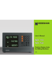
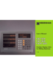
User’s Manual
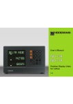
Position Display Units
for Milling Machines
6/99
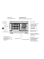
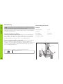
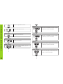
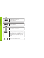
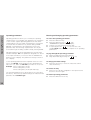
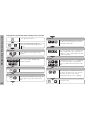
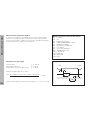
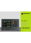
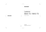
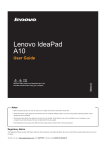
Position display
(ND 720 only two axes)
Numerical input
Status display:
SET = Datum setting
REF = blinking:
Traverse the
reference points.
On continuously:
Reference points
have been traversed.
∆ = Distance-to-go display
1
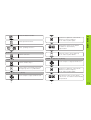
• Select coordinate axes
(ND 720 only X and Y)
• Select axis-specific operating parameters
• Change the algebraic sign
• Call the last dialog
• In the parameter list:
change parameters
• Confirm entry
• In the parameter list
page forward
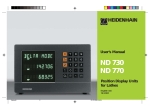
2 Datum 1 or 2
Inch = Display in inches
SCL = Scaling factor
->❘❘<- = Probing an edge /
centerline
R = Radius/diameter display
R+/– = Radius compensation
HEIDENHAIN
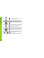
Call radius compensation
of the current tool
• Select special functions
• In the list of special functions
page forward
• Select datum 1 or 2
• Page backward in the list of
special functions
• Page backward in the list of
parameters
• Cancel entry
• Reset the operating mode
• Zero the selected axis
(if activated in P80)
• Select parameters
CL plus two-digit number
Part I Operating Instructions
ND 720 for two axes
ND 760 for three axes
Fundamentals
4
Switch-On, Traversing the Reference Points
9
AA00
AA00
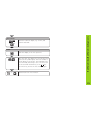
About this manual
This manual is divided into two parts:
Part I: Operating Instructions
• Fundamentals of positioning
• ND functions
Part II: Installation and specifications
• Mounting the display unit on the machine
• Description of operating parameters
• Switching inputs, switching outputs
Datum Setting
Datum setting with the tool
Datum setting with the KT Edge Finder
10
10
13
Tool Compensation
18
Moving the Axes with Distance-To-Go
19
Bolt Hole Circles and Bolt Circle Segments
21
Linear Hole Patterns
24
Working with a Scaling Factor
27
Error Messages
28
Part II
Installation and
Specifications
Page 29
Part I Operating Instructions
This manual is for the ND display units with the
following software numbers or higher:
3
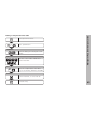
Fundamentals
Fundamentals
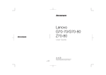
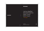
+Y
+Z
You can skip this chapter if you are already familiar with
coordinate systems, incremental and absolute dimensions,
nominal positions, actual positions and distance-to-go.
Graduation
+X
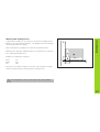
Coordinate system
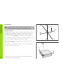
The Cartesian1) coordinate system is used to describe the geometry of
a workpiece. The Cartesian coordinate system consists of three
mutually perpendicular axes X, Y and Z. The point of intersection of
these axes is called the datum or origin of the coordinate system.
–X
Datum or origin
Think of the axes as scales with divisions (usually in millimeters) which
allow us to fix points in space referenced to the datum.
–Z
–Y
To determine positions on a workpiece, the coordinate system is
“laid” onto the workpiece.
Z
The machine axes are parallel to the axes of the coordinate system.
The Z axis is normally the tool axis.
Y
X
1)
4
Named in honor of the French mathematician and philosopher
René Descartes (1596 to 1650)
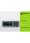
In the context of a numerical position display unit, datum setting
means bringing the workpiece and the tool into a defined position in
relation to each other and then setting the axis displays to the value
that corresponds to that position. This establishes a fixed relationship
between the actual positions of the axes and the displayed positions.
0
-125
-216,5
Fundamentals
250
125
216,5
0
1225
250
-250
150
0
750
320
-150
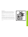
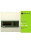
Relative
datum
0
The workpiece drawing always indicates one absolute datum (the
datum for absolute dimensions). However, it may contain additional
relative datums.
216,5
125
300±0,1
The workpiece drawing is used as the basis for machining the
workpiece. To enable the dimensions in the drawing to be converted
into traverse distances of machine axes X, Y and Z, each drawing
dimension requires a datum or reference point on the workpiece
(since a position can only be defined in relationship to another
position).
-250
-216,5
-125
Datum setting
900
950
700
450
325
Absolute
datum
0
0
You can set 2 absolute datum points and store them in nonvolatile
memory.
5
Fundamentals
Absolute workpiece positions
Z
Each position on the workpiece is uniquely defined by its absolute
coordinates.
Example
Absolute coordinates of position 1:
X =
10 mm
Y =
5 mm
Z =
0 mm
Y
If you are working according to a workpiece drawing with absolute
dimensions, then you are moving the tool to the coordinates.
X
1
5
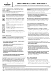
Relative workpiece positions
10
A position can also be defined relative to the previous nominal
position. The datum for the dimension is then located at the previous
nominal position. Such coordinates are termed relative coordinates or
chain dimensions. Incremental coordinates are indicated by a
preceding I.
Example
Relative coordinate of position 2 referenced to
position 1:
IX =
10 mm
IY =
10 mm
Z
Y
2
If you are working according to a workpiece drawing with incremental
dimensions, then you are moving the tool by the dimensions.
10
1
Sign for incremental dimensioning
6
A relative dimension has a positive sign when the axis is moved in the
positive direction, and a negative sign when it is moved in the
negative direction.
1
10
5
10
X
Z
The position to which the tool is to move is called the nominal
R
given moment is called the actual position ( I ).
The distance from the nominal position to the actual position is called
S
I
position ( S ). The position at which the tool is actually located at any
Y
the distance-to-go ( R ).
X
Fundamentals
Nominal position, actual position and distance-to-go
Sign for distance-to-go
When you are using the distance-to-go display, the nominal position
becomes the relative datum (display value 0). The distance-to-go is
therefore negative when the tool moves in the positive axis direction,
and positive when it moves in the negative axis direction.
7
Fundamentals
Position encoders
The position encoders on the machine convert the movements of the
machine axes into electrical signals. The ND display unit evaluates
these signals, determines the actual position of the machine axes and
displays the position as a numerical value.
Z
Workpiece
Y
If the power is interrupted, the relationship between the machine axis
positions and the calculated actual positions is lost. The reference
marks on the position encoders and the REF reference mark
evaluation feature enable the ND to quickly reestablish this
relationship again when the power is restored.
X
Position
encoder
Reference marks
The scales of the position encoders contain one or more reference
marks. When a reference mark is crossed over, a signal is generated
which identifies that position as a reference point (scale datum =
machine datum).
When this reference mark is crossed over, the ND's reference mark
evaluation feature (REF) restores the relationship between axis slide
positions and display values which you last defined by setting the
datum. If the linear encoders have distance-coded reference marks,
you only need to move the machine axes a maximum of 20 mm to do
this.
8
Scale in linear encoder
Reference marks
Reference marks
0è1
Turn on power (switch located on rear panel).
“REF” and decimal points in status display blink.
ENT...CL
ENT
Confirm reference traverse mode. “REF”
remains on continuously. Decimal points blink.
Cross over the reference marks in all axes in any
sequence. Each axis display becomes active
when its reference mark is crossed over.
Crossing over the reference marks stores the most recently defined
assignment of display values to axis slide positions for datum points 1
and 2 in nonvolatile memory.
Note that if you choose not to traverse the reference marks (by
clearing the dialog ENT ... CL with the CL key), this relationship will be
lost if the power is interrupted or when the unit is switched off.
If you wish to use multipoint axis error compensation you
must traverse the reference marks (see “Multipoint axis error
compensation”)!
Switch-On, Traversing the Reference Marks
Switch-On, Traversing the Reference Marks
9
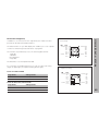
Datum Setting
Datum Setting
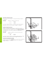
Datum setting with the tool
If you want to save the datum points in nonvolatile memory,
you must first cross over the reference marks.
Example:
Only after crossing over the reference marks can you set new datums
or activate existing ones.
Working plane
X / Y
Tool axis
Z
There are two ways to set datums:
Tool radius
R = 5 mm
Touch the workpiece with the tool and then set the desired datum
(see example). You can also touch two edges and set the centerline
between them as a datum. The dimensions of the tool used for this
are automatically accounted for (see “Tool Compensation”).
Axis sequence
for datum setting
X–Y–Z
Probe the workpiece with the edge finder and then set the desired
datum, or probe two edges and set the centerline as datum (see
example). The stylus radius and length are automatically accounted for
if they have been entered in parameters P25 and P26, respectively
(see “operating parameters”).
Z
R = 5 mm
After you have set a datum, it can be activated as follows:
Y
Select datum 1 or 2.
X
1
2
10
X position is captured. “SET” blinks.
Retract tool from workpiece.
The ❘<- status symbol lights.
ENT
SPEC
FCT
SPEC
FCT
or
Select special functions.
Select “probing function.”
0
PROBING
ENT
•
•
•
ENT
Select the Y axis. “SET” lights up.
The ❘<- status symbol blinks.
Y
Confirm selection.
Enter position value for the datum.
Tool radius is automatically
compensated.
Datum Setting
Select the datum number.
PROBE Y (appears only briefly)
PROBE EDGE
ENT
X
Touch workpiece edge 2 with the tool.
Confirm “Probe edge.”
Select X axis (if not already selected).
SET lights up. The ❘<- symbol blinks.
Y position is captured. “SET” blinks.
Retract tool from workpiece.
The ❘<- status symbol lights.
ENT
PROBE X (appears only briefly)
Touch workpiece edge 1 with the tool.
•
•
0
•
•
•
•
•
ENT
Enter position value for the datum
in the Y axis. Tool radius is automatically
compensated.
11
Datum Setting
Select the Z axis. “SET” lights.
The ❘<- status symbol blinks.
Z
PROBE Z (appears only briefly)
Touch the top of the workpiece with
the tool.
ENT
0
SPEC
SPEC
FCT
FCT
12
ENT
or
Z position is captured. “SET” blinks.
Retract the tool from the workpiece.
The ❘<- status symbol lights.
Enter the position value for the datum
in the Z axis.
After setting the datum, exit the
probing functions.
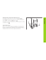
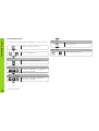
The ND position display units provide the following probing functions:
Edge Probing:
Setting a workpiece edge as datum
Center Probing: Setting a midpoint between two workpiece edges as
datum
Datum Setting
Datum Setting with the KT Edge Finder
The probing functions are accessible in the SPEC FCT mode of
operation.
Before using the edge finder you must enter the stylus diameter and
length in parameters P25 and P26, respectively (see “Operating
Parameters”).
During all probing functions, the ND position display unit accounts for
the entered dimensions.
The Edge Probing and Center Probing functions are describe on the
following pages.
13
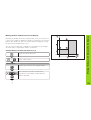
Datum Setting
Probing a workpiece edge to find a datum
Z
The edge to be probed is parallel to the Y axis. You can probe edges
and surfaces as described below to set all the coordinates of a datum.
Select a datum number.
Y
X?
SPEC
FCT
Select special functions.
Select “probing functions.“
SPEC
FCT
PROBING
ENT
Confirm “probing” function.
PROBE EDGE
ENT
14
•
•
•
Confirm “probe edge” function.
X
PROBE X (appears only briefly)
Move the edge finder to edge of workpiece until
indicator in edge finder lights. “SET” begins to
blink. The ND displays the position of the edge.
The ❘< status symbol lights.
Datum Setting
If required, select the X axis. “SET” lights.
The ❘< status symbol starts blinking.
X
Back the edge finder away from the workpiece.
5
2
SPEC
FCT
or
ENT
Assign a position value to this edge, e.g. 52.
Exit the probing function.
15
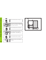
Datum Setting
Probing workpiece edges to find a midpoint datum
Z
The edges probed must be parallel to the Y axis.
Follow the procedure below for all midpoints between two edges.
Select a datum number.
Y
2
1
SPEC
FCT
SPEC
FCT
or
Select the special functions.
Select the probing function.
PROBING
ENT
Confirm the probing function.
PROBE EDGE
or
16
•
•
•
Select the midpoint probing function.
M
X?
X
Confirm the “probe midpoint” function.
“SET” lights.
ENT
X
Datum Setting
Z
PROBE MIDP.
ENT
If required, select the X axis and confirm with
ENT. The ->❘❘<- status symbol starts blinking.
Y
2
1
1ST POS X (appears only briefly)
M
X?
X
Move edge finder toward workpiece edge 1
until the indicator in the edge finder lights. Back
edge finder away from the workpiece.
2. POS X (appears only briefly)
Move edge finder toward workpiece edge 2 until
the indicator in the edge finder lights. “SET”
begins to blink. Back the edge finder away from
the workpiece. The ->❘❘<- symbol begins to blink.
2
6
SPEC
FCT
or
ENT
Set the position value for the midpoint between
the edges, e.g. 26.
Exit the probing functions.
17
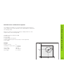
Tool Compensation
Tool Compensation
You can enter the axis, length and diameter of the current tool.
Z
Set the tool axis.
Select the special functions.
SPEC
FCT
TOOL AXIS
SPEC
FCT
SPEC
FCT
Select “tool diameter.”
or
TOOL DATA
Confirm tool data input mode.
ENT
TOOL DIAM.
2
TOOL
5
0
ENT
Enter the tool diameter, e.g. 20 mm,
and confirm with ENT.
LENGTH
0
ENT
•
•
•
1) only by ND 760
18
TOOL AXIS
1)
Enter the tool length, e.g. 50 mm,
and confirm with ENT.
or
Exit the special functions.
Normally, the display shows the actual position of the tool. However, it
is often more helpful to display the distance remaining to the nominal
position (the distance-to-go). You can then position simply by moving
the axis until the display value is zero.
You can enter the absolute coordinates in the distance-to-go display.
An active radius compensation will be considered.
Example: Milling a shoulder with distance-to-go
Select the special functions.
SPEC
FCT
SPEC
FCT
or
Select “delta mode.”
DELTA MODE
Confirm your selection, the ∆ symbol lights.
ENT
Y 2 0
R+-
Select the axis, enter the nominal value,
e.g. 20 mm, select radius compensation R+,
confirm with ENT.
Moving the Axes with Distance-To-Go Display
Moving the Axes with Distance-To-Go Display
ENT
•
•
•
19
Moving the Axes with Distance-To-Go Display
Move the machine axis to zero (1).
X
3
0
R+-
R+-
ENT
Move the machine axis to zero (2).
Y
5
R+-
0
Select the axis, enter the nominal
value, e.g. 50 mm, select radius
compensation R+, confirm with ENT.
ENT
Move the machine axis to zero (3).
SPEC
FCT
20
Select the axis, enter the nominal value,
e.g. 30 mm, select radius compensation
R–, and confirm with ENT.
or
ENT
If appropriate, switch off the distanceto-go display.
Bolt Hole Circles/Bolt Hole Circle Segments
Bolt Hole Circles and Bolt Circle Segments
Your display unit enables you to quickly and easily produce bolt hole
circles and bolt hole circle segments. The required data is requested in
the message field.
Each hole can be moved to by traversing to display value zero. This
requires entry of the following data:
Number of holes (maximum: 999)
Circle center
Circle radius
Starting angle for first hole
Angle step between the holes (only for circle segments)
Hole depth
Example
Y
30°
0
50
0
50
Circle radius
Starting angle
Hole depth
8
X = 50 mm
Y = 50 mm
20 mm
30 degrees
Z = –5 mm
R2
Number of holes
Coordinates of the center
0
•
•
•
•
•
•
X
21
Bolt Hole Circles/Bolt Hole Circle Segments
Select the special functions.
SPEC
FCT
CENTER X
Select “bolt hole” circle.
SPEC
FCT
X
5
Enter the X coordinate of circle center,
e.g. 50 mm, confirm with ENT.
0
Enter the Y coordinate of circle center,
e.g. 50 mm, confirm with ENT.
ENT
BOLT HOLE
CENTER Y
Confirm your selection.
ENT
ENT
FULL CIRCLE
if req.
5
Y
ENT
Confirm “full circle.”
RADIUS
2
NUMB. HOLES
8
ENT
•
•
•
Enter the number of holes, e.g. 8.
Confirm with ENT.
0
Enter the radius of the bolt hole circle,
e.g. 20 mm. Confirm with ENT.
ENT
START ANGLE
3
0
ENT
22
0
•
•
•
Enter the start angle for the first hole,
e.g. 30°. Confirm with ENT.
Enter the total hole depth, e.g. –5 mm, and
confirm with ENT.
5
ENT
START
ENT
After the start, the distance-to-go mode becomes
active (the ∆ symbol lights). The hole number is
shown briefly in the X axis. The individual holes
are reached by traversing to zero. The holes can
be selected with the ENT key or the 1 2 key.
The minus key shows the hole number again.
ENT
SPEC
FCT
Start the display of the hole positions.
or
Bolt Hole Circles/Bolt Hole Circle Segments
HOLE DEPTH
Exit the bolt hole circle function.
23
Linear Hole Patterns
Linear Hole Patterns
The linear hole pattern feature allows you to easily create rows of
holes to cover an area. The required data are requested in the
message field.
You can position to each hole by traversing to display value zero.
The following data are required:
•
•
•
•
•
•
•
Coordinates of the first hole
Number of holes per row (maximum: 999)
Spacing between holes
Angle between the rows and the reference axis
Hole depth
Number of rows (maximum: 999)
Spacing between rows
Example
Coordinates of the first hole
12
16
9
5
1
15
8
7
6
2
3
4
20
Number of holes per row
Spacing between holes
Angle
Hole depth
Number of rows
Spacing between rows
Y
X = 20 mm
Y = 15 mm
4
16 mm
15 degrees
Z = -30 mm
3
20 mm
15°
20
24
0
0
X
HOLES ROW
ENT
Select “hole pattern.”
SPEC
FCT
LIN. HOLE
Enter the number of holes per row,
e.g. 4, and confirm with ENT.
HOLE SPACE
Confirm “linear hole” pattern.
ENT
1
6
Enter the spacing between holes in the
row and confirm with ENT.
5
Enter the angle, e.g. 15 degrees,
and confirm with ENT.
Linear Hole Patterns
Select special functions.
SPEC
FCT
ENT
1ST HOLE X
2 0
ENT
Enter the X coordinate of the first holes,
e.g. 20, and confirm with ENT.
ANGLE
1
1ST HOLE Y
1 5
•
•
•
ENT
ENT
Enter the Y coordinate of the first holes,
e.g. 15, and confirm with ENT.
HOLE DEPTH
3
0
Enter the hole depth, e.g. –30 mm,
and confirm with ENT.
ENT
•
•
•
25
Linear Hole Patterns
NUMBER ROW
3
ENT
Enter the number of rows, e.g. 3,
and confirm with ENT.
ROW SPACE
2
0
ENT
Enter the spacing of the rows, e.g. 20,
and confirm with ENT.
START
ENT
The distance-to-go mode is now active (the ∆
symbol lights). The hole number appears briefly
in the X axis. Move to the individual hole
positions by traversing to the display value zero.
Hole can be selected with the ENT key or with
the 1 2 key. Pressing the minus key shows
the hole number again.
ENT
SPEC
FCT
26
Start the display of hole positions.
or
Exit the linear hole patterns function.
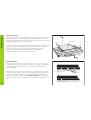
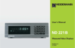
Scaling factors enable you to increase or decrease the display values
based on the actual traverse distance. The display values are changed
symmetrically about the datum.
Scaling Factor
Working with Scaling Factors
Y
Enter scaling factors separately for each axis in parameter P12.
∗ 3.0
Parameter P11 activates and deactivates the scaling factors in all axes
(see “Operating Parameters”).
Example for enlarging a workpiece:
3.5
3.0
ON
∗ 3.5
X
0
P12.1
P12.2
P11
0
1
2
This results in a larger workpiece as shown in the illustration at right:
1 is the original size, 2 is with axis-specific scaling factors.
If a scaling factor is active, “SCL” lights in the status display.
27
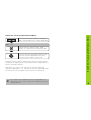
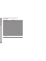
Error Messages
Error Messages
Message
RS TOO FAST
SIGNAL X
PROB. ERROR
DSR MISSING
ERR. REF. X
FORMAT. ERR.
FRQ. ERR X
ERR. MEMORY
28
Cause and Effect
Time interval between two commands
too short.
Encoder signal is too weak, e.g. when an
encoder is contaminated.
Before touching off on the workpiece,
the tool must move by a distance of at
least 0.2 mm.
The connected device is not
transmitting a DSR signal..
The spacing of the reference marks as
defined in P43 is not the same as the
actual spacing.
Data format, baud rate etc. do not
match.
The input frequency for this encoder
input is too high. This can occur when
the scale is moved too fast.
Check sum error: Check the datum,
operating parameters and compensation
values for multipoint axis error compensation. If the error recurs, contact your
service agency!
To erase error messages:
After you have removed the cause of error:
➤ Press the CL key.
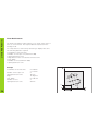
Items Supplied
30
Connections on Rear Panel
31
Mounting
32
Power connection
32
Connecting the Encoders
33
Operating Parameters
Entering/changing operating parameters
Operating parameter list
34
34
35
Linear Encoders
Setting the display step
Display step, signal period and subdivision
Compatible HEIDENHAIN linear encoders
38
38
38
39
Multipoint Axis Error Compensation
41
Pin Layout of X10
44
Data Interface RS-232-C/V.24
45
Measured Value Output
46
Specifications
Dimensions of ND 720/ND 760
52
53
Part II Installation and Specifications
Part II Installation and Specifications
29
Items Supplied
Items Supplied
• ND 720 for 2 axes
or
• ND 760 for 3 axes
• Power connector Id. Nr. 257 811-01
• User's Manual
Optional Accessories
• Tilting base for housing bottom
Id. Nr. 281 619-01
• KT 130 Edge Finder Id. Nr. 283 273-01
30
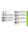
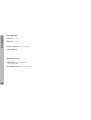
Connections on Rear Panel
Connections on Rear Panel
ID label
Power switch
Power input
• Edge finder input
• RS-232-C/V.24
data interface
Protective ground
Encoder inputs X1 to X3
Rubber feet with M4 thread
The interfaces X1, X2, X3, and X10 comply with the requirements for electrical separation according to EN 50178!
31
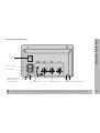
Mounting/Power Connection
Mounting
ND 720/ND 760
To mount the display unit on a support, use the M4 threaded holes in
the rubber feet. You can also mount the display unit on the optional
tilting base.
HE
IDE
NH
AIN
Tilting base
Support
Power Connection
Power leads: L and N ,
Connect protective ground to
!
• Danger of electrical shock!
Connect a protective ground. This connection must never
be interrupted.
• Unplug the power cord before opening the housing.
To increase the noise immunity, connect the ground terminal
on the rear panel to the central ground point of the machine.
(Minimum cross-section: 6 mm2).
32
The display unit will operate over a voltage range of 90 Vac to 260 Vac.
A voltage selector is therefore not necessary.
Your display unit will accept all HEIDENHAIN linear encoders with
sinusoidal output signals (7 to 16 µApp) and distance-coded or single
reference marks.
Assignment of the encoder inputs
Encoder input X1 is for the X axis
Encoder input X2 is for the Y axis
Encoder input X3 is for the Z axis (ND 760 only)
Encoder monitoring system
Your display unit features a monitoring system for checking the
amplitude and frequency of the encoder signals. If it detects a faulty
signal, one of the following error messages will be generated:
Z
Y
X
Connecting the Encoders
Connecting the Encoders
SIGNAL X
FRQ. X
Encoder monitoring can be activated with parameter P45.
If you are using linear encoders with distance-coded reference marks,
the encoder monitoring system also checks whether the spacing of
the reference marks as defined in parameter P43 is the same as the
actual spacing on the scales. If it is not, the following error message
will be generated:
ERR. REF. X
33
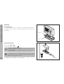
Operating Parameters
Operating parameters
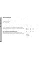
Entering and changing operating parameters
Operating parameters allow you to modify the operating
characteristics of your display unit and define the evaluation
of the encoder signals. Operating parameters that can be
changed by the user are called user parameters, and can be
accessed with the SPEC FCT key and the dialog “PARAMETER” (user parameters are identified as such in the
parameter list). The full range of parameters can only be
accessed through the dialog “CODE“ and by entering 95148.
To access the operating parameters
➤
➤
➤
➤
Operating parameters are designated by the letter P and a
number. Example: P11.. The parameter designation is shown
in the input field when you select it with the DATUM and
ENT key in the X display. The parameter setting is shown in
the Y display.
To page through the operating parameters
Some operating parameters have separate values for each
axis. In the ND 760, these parameters are identified by an
index of 1 to 3, and in the ND 720 by an index of one to two.
Example: P12.1 scaling factor, X axis
P12.2 scaling factor, Y axis
P12.3 scaling factor, Z axis (ND 760 only)
To change parameter settings
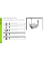
The operating parameters are preset before the unit leaves
the factory. These factory default settings are indicated in the
parameter list in boldface type.
➤
➤
➤
Page forwards by pressing the ENT key.
Page backwards by pressing the 1 2 key.
Press the minus key or enter the value and confirm
with the ENT key.
To correct an entry
➤
Press CL: the old value reappears in the input line and
becomes effective again.
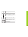
To exit the operating parameters
➤
34
Press the SPEC FCT key.
Press the SPEC FCT key or 1 2 , until
“PARAMETER” appears in the X display.
Confirm your selection by pressing ENT.
If required, press the 1 2 key to enter the code
number 95148 and access the complete list of operating
parameters.
Press the SPEC FCT or CL key.
P30.1 to P30.3 Counting direction
P1 Unit of measure 1)
Positive counting direction with
positive direction of traverse
DIRECT. POS
Negative counting direction with
positive direction of traverse
DIRECT. NEG
Display in millimeters
Display in inches
MM
INCH
P3.1 to P3.3 Radius/diameter display 1)
Display position value as radius
Display position value as diameter
RADIUS
DIAMETER
P11 Activate scaling factor 1)
Active
Not active
SCALING ON
SCALING OFF
P12.1 to P12.3 Define scaling factor 1)
Enter a scaling factor separately for each axis:
Entry value > 1: workpiece will “grow”
Entry value = 1: workpiece will remain the same size
Entry value < 1: workpiece will “shrink”
Input range:
0.100000 to 9.999999
Default setting:
1.000000
P32.1 to P32.3 Subdivision of the encoder signals
1024 / 1000 / 800 / 512 / 500 / 400 / 256 / 200 / 128 / 100 /
80 / 64 / 50 / 40 / 20 / 10 / 8 / 5 / 4 / 2 / 1 / 0.8 / 0.5 / 0.4 / 0.2 /
0.1
P33.1 to P33.3 Counting mode
Operating Parameters
List of Operating Parameters
0-1-2-3-4-5-6-7-8-9
0-2-4-6-8
0-5
P38.1 to P38.3 Decimal places
2/3/4/5/6/7/8
P25 Stylus diameter 1)
Input range (mm):
Default setting:
0.000 to 999.999
6
P26 Stylus length 1)
Input range (mm):
0.000 to 999.999
1)
User parameter
35
Operating Parameters
P40.1 to P40.3 Select type of axis error compensation
P45.1 to P45.3 Encoder monitoring
No axis error compensation
Amplitude and frequency
monitoring
No monitoring
Linear error compensation active,
multipoint error comp. not active
CORR. OFF
CORR. LIN
P48.1 to P48.3 Activate axis display
Multipoint error compensation active,
linear error compensation not active CORR. ABS
Axis display active
Not active
P41.1 to P41.3
P49.1 to P49.3 Axis designation for measured value output1)
Linear axis error compensation
AXIS ON
AXIS OFF
Input range (µm):
−99999 to +99999
Factory default setting:
0
Example: Displayed length
Ld = 620.000 mm
Actual length (as determined for example with
the VM 101 from HEIDENHAIN)
La = 619.876 mm
Difference ∆L = La – Ld = – 124 µm
Compensation factor k:
k = ∆L/Ld = – 124 µm/0.62 m = – 200 [µm/m]
An axis designation for the measured value output can be set
through the number of the ASCII character. The axis
designation is output together with the measured value.
P43.1 to P43.3 Reference marks
P50 Baud rate 1)
One reference mark
Distance-coded with
Distance-coded with
Distance-coded with
Distance-coded with
(SP: signal period)
500 • SP
1000 • SP
2000 • SP
5000 • SP
SINGLE REF.M.
500
SP
1000
SP
2000
SP
5000
SP
Input range:
Measured value output disabled
ASCII character from ASCII table
Default setting:
Evaluation
No evaluation
REF. X ON
REF. X OFF
0 to 127
0
1 to 127
P49.1
88
P49.2
89
P49.3
90
110 / 150 / 300 / 600 / 1200 / 2 400 / 4 800 / 9600 /
19 200 / 38 400
P51 Line feeds for measured value output 1)
Input range:
Default setting:
P44.1 to P44.3 Reference mark evaluation
36
ALARM ON
ALARM OFF
1)
User parameter
0 to 99
1
Set to zero with CL
No set to zero with CL
Operating Parameters
P80 Function of the CL key
CL....RESET
CL......OFF
P96 Measured value output for probing
Measured value output active
Measured value output not active
PROBE ON
PROBE OFF
P97 Characters for measured values
ASCII characters for designation of the measured values for
output through probing, contact, or pulse.
Input range:
No ASCII character
ASCII character from ASCII table
0 to 127
0
1 to 127
P98 Conversational language 1)
German
English
French
Italian
Dutch
Spanish
Danish
Swedish
Finnish
Czech
Polish
Hungarian
Portuguese
LANGUAGE
LANGUAGE
LANGUAGE
LANGUAGE
LANGUAGE
LANGUAGE
LANGUAGE
LANGUAGE
LANGUAGE
LANGUAGE
LANGUAGE
LANGUAGE
LANGUAGE
D
GB
F
I
NL
E
DK
S
FI
CZ
PL
H
P
1)
User parameter
37
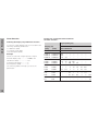
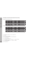
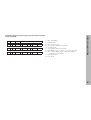
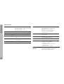
Linear Encoders
Linear Encoders
Selecting the display step with linear encoders
Signal period [µm]
To select a certain display step you must define the
following operating parameters:
Display step
[mm]
[inch]
2
4
10
20
40
100
200 12 800
P32: Subdivision
• Subdivision (P32)
• Counting mode (P33)
• Decimal points (P38)
0.000 005 0.000 000 2 400
Example
Linear encoder with a signal period of 10 µm
0.000 01
0.000 02
0.000 05
Desired display step ................ 0.000 5 mm
Subdivision (P32) ..................... 20
Counting mode (P33) ............... 5
Decimal places (P38) ............... 4
The following tables will help you select the
parameters.
38
Display step, signal period and subdivision
for linear encoders
–
–
–
–
–
–
–
0.000 000 5 200
0.000 001 100
0.000 002
40
–
–
80
–
–
–
–
–
–
–
–
–
–
–
–
–
–
–
–
–
–
0.000 1
0.000 2
0.000 5
0.000 005
0.000 01
0.000 02
20
10
4
40 100 200
20
50 100
8
20 40
–
–
80
–
–
–
–
–
–
–
–
–
0.001
0.002
0.005
0.000 05
0.000 1
0.000 2
2
1
0.4
4
2
0.8
10
5
2
40 100
–
20
50 100
8
20
40
–
–
–
0.01
0.02
0.05
0.000 5
0.001
0.002
0.2
–
–
0.4
–
–
1
2
0.5
1
0.2 0.4
4
2
0.8
10
5
2
20
10
4
–
–
256
0.1
0.2
0.005
0.01
–
–
–
–
0.1 0.2
–
–
0.4
–
1
–
2
–
128
64
20
10
4
MT xx
10
LS 303/303C
LS 603/603C
20
P 32
P 33
P 38
0,0005
4
5
4
0,0002
10
2
4
0,0001
20
1
4
-/single
0,00005
40
5
5
Recommended only for LIP 401
0,00002
100
2
5
0,00001
200
1
5
0,000005
400
5
6
single/5000 0,001
4
1
3
8
5
4
0,0005
0,0002
20
2
4
40
1
4
0,0001
0,00005
80
5
5
single
Recommended only for LIP 101
0,00002
200
2
5
0,00001
400
1
5
single
0,0005
20
5
4
0,0002
50
2
4
0,0001
100
1
4
single/1000 0,01
2
1
2
0,005
4
5
3
0,00002
0,00001
0,000005
0,000002
P 32
4
10
20
40
P 33
2
1
5
2
P 38
5
5
6
6
0,000001
0,0000005
0,0000002
0,00005
0,00002
0,00001
0,000005
0,000002
100
200
400
4
8
20
40
80
1
5
2
5
2
1
5
2
6
7
7
5
5
5
6
6
0,000001
0,0000005
0,00002
0,00001
0,000005
0,0005
0,0002
200
400
20
50
100
2
4
1
5
2
1
5
5
2
6
7
5
5
6
4
4
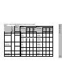
Linear Encoders
Decimal
places
Count
Display
step [inch]
Decimal
places
4
P 43
single
Inches
Display
step [mm]
Count
LF 103/103C
LF 401/401C
LIF 101/101C
LIP 501/501C
LIP 101
2
Millimeters
Subdivision
CT
MT xx01
LIP 401A/401R
Reference
marks
Subdivision
Model
Signal period
[µm]
Parameter settings for HEIDENHAIN linear encoders with 11 µAPP signals
39
P 32
20
40
P 33
1
5
P 38
3
4
8
5
3
single/2000 0,005
0,002
20
2
3
0,001
40
1
3
0,0005
80
5
4
Recommended only for LB 302
0,0002
200
2
4
0,0001
400
1
4
100
single/1000 0,005
20
5
3
0,002
50
2
3
0,001
100
1
3
12800 single
0,1
128
1
1
0,05
256
5
2
40
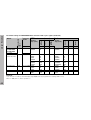
Decimal
places
P 43
single/1000 0,001
0,0005
Decimal
places
Display
step [inch]
Count
LIM 102
Inches
Display
step [mm]
Subdivision
LB 301/301C
20
Millimeters
Count
LS 106/106C
LS 406/406C
LS 706/706C
ST 1201
LB 302/302C
LIDA 10x/10xC
Reference
marks
Subdivision
Model
Signal period
[µm]
Linear Encoders
Parameter settings for HEIDENHAIN linear encoders with 11 µAPP signals (continued)
0,00005
0,00002
P 32
20
40
P 33
5
2
P 38
5
5
0,0002
0,0001
0,00005
0,00002
8
20
40
80
2
1
5
2
4
4
5
5
0,000001
0,0000005
0,0002
0,0001
0,00005
0,005
0,002
200
400
20
50
100
128
256
1
5
2
1
5
5
2
5
6
4
4
5
3
3
Example:
Your encoder: LS 303 C, desired display step: 0,005 mm (5 µm), parameter settings: P01 = mm,
P43 = 1 000, P32 = 4, P33 = 5, P38 = 3
40
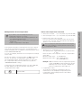
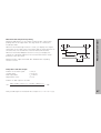
If you want to use the multipoint axis error
compensation feature, you must
• activate this feature with operating parameter 40
(see "Operating Parameters"),
• traverse the reference marks after switching on the
display unit,
• enter a compensation value table.
Your machine may have a nonlinear axis error due to factors
such as axis sag or drivescrew errors. Such deviations are
usually measured with a comparator measuring system (such
as the HEIDENHAIN VM 101).
Entries in the compensation value table
•
Axis to be corrected:
•
Axis causing the error: X, Y or Z (Z axis only with ND 760)
•
Datum for the axis to be corrected:
Here you enter the point starting at which the axis with
error is to be corrected. This point indicates the absolute
distance to the reference point.
Do not change the datum point after measuring the
axis error and before entering the axis error into the
compensation table.
•
You can, for example, determine the screw pitch error X=F(X)
for the X axis.
An axis can only be corrected in relation to one axis that has
an error. In each axis, a compensation value table with
16 compensation values can be generated. You can select
the compensation table with the SPEC FCT key and the
“PARAMETER\CODE” dialog.
To determine the compensation values (e.g. with a VM 101),
the REF display must be selected after selecting the
compensation-value table.
R+-
Select the REF.
X, Y or Z (Z axis only with ND 760)
Spacing of the compensation points
The spacing of the compensation points is expressed as
2x [µm].
Enter the value of the exponent x into the compensation
value table.
Minimum input value:
6 (= 0.064 mm)
Maximum input value: 20 (= 1048.576 mm)
23 (= 8388.608 mm)
Multipoint Axis Error Compensation
Multipoint Axis Error Compensation
Example: 900 mm traverse and 15 compensation points:
results in 60.000 mm spacing between points.
Nearest power of two: 216 [µm] = 65.536 mm
Entry in compensation value table: 16
•
Compensation value
You enter the measured compensation value (in
millimeters) for the displayed compensation point.
Compensation point 0 always has the value 0 and
cannot be changed.
41
Multipoint Axis Error Compensation
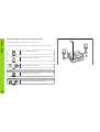
Selecting the compensation table, entering an axis correction
Select special functions.
SPEC
FCT
DATUM X
2
SPEC
FCT
7
Select the "Parameter" function if
required, by repeatedly pressing the
1 2 key
or
Enter the active datum for the error on
the axis to be corrected (e.g. 27 mm)
and confirm with ENT.
SPACING X
PARAMETER
Select dialog for entering the code
number.
ENT
CODE
1
0
1 0 5 2
9 6
Enter the spacing of the compensation
points on the axis to be corrected, for
example 210 µm (equals 1024 mm) and
confirm with ENT.
ENT
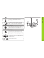
ENT
0
0
1
ENT
Compensation point no. 1 is displayed.
Enter the associated compensation
value (e.g. 0.01 mm) and confirm with
ENT.
28.024
X
ENT
Enter all further compensation points. If
you press the minus key, the unit will
show the number of the current
compensation point in the X display.
ENT
X
ENT
27.000
Enter code number 105296 and
confirm with ENT.
AXIS X
FCT. X
X
42
ENT
ENT
•
•
Enter the axis causing the error (e.g. X)
(screw pitch error), and confirm with
ENT.
SPEC
FCT
or
Conclude entry.
Select special functions.
SPEC
FCT
SPEC
FCT
Select “parameter.”
or
PARAMETER
Select the dialog for entering the code
number.
ENT
CODE
1 0 5 2
9 6
AXIS
Enter the code number 105296 and
confirm with ENT.
ENT
Multipoint Axis Error Compensation
Deleting a compensation value table
X
Select the compensation value table
(e.g., for the Z axis), and delete the table.
Z
DELETE Z
ENT
SPEC
FCT
Confirm with ENT, or cancel with CL.
Conclude entry.
43
Pin Layout of X10
Pin Layout of X10 for KT 130 Edge Finder and
Data Interface
Pin
Signal
1
Internal shield
2
Standby
3
RXD
Receive data
4
RTS
Request to send
5
CTS
Clear to send
6
7
UP
SIGN. GND
8
+5 V
Signal ground
UP
0V
9
TXD
Transmit data
10
DSR
Data set ready
11
DTR
Data terminal ready
12
Meas. value output by contact
13
Switching signals
14
Meas. value output by pulse
15
44
Function
CHASSIS
GND
Housing
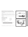
In addition to a connection for the edge finder, the X10 socket also
provides an RS-232-C/V.24 data interface.
Full wiring
ND
The data interface on your ND display unit enables you to use a printer
or a PC for transferring measured values or programs.
X10
CHASSIS GND 15
CHASSIS GND
TXD
9
TXD
RXD
RTS
CTS
3
4
5
RXD
RTS
CTS
The interface is permanently set to the following data format:
1 start bit
7 data bits
Even parity bit
2 stop bits
SIGNAL
DSR 10
GND 7
SIGNAL
DSR
GND
DTR
DTR 11
The baud rate is set with parameter P50.
For connection to peripheral devices you can use either full wiring
(figure at upper right) or simplified wiring (below right).
RS-232-C / V.24 Data Interface
RS-232-C/V.24 (Option)
Simplified wiring
Levels for TXD and RXD
Logic levels
ND
Voltage levels
“1”
– 3 V to – 15 V
“0”
+ 3 V to +15 V
Levels for RTS, CTS, DSR and DTR
Logic levels
Voltage levels
“1”
+ 3 V to +15 V
“0”
– 3 V to – 15 V
X10
CHASSIS GND 15
CHASSIS GND
TXD
9
TXD
RXD
RTS
CTS
3
4
5
RXD
RTS
CTS
DSR 10
GND 7
DSR
SIGNAL GND
DTR 11
DTR
SIGNAL
45
Measured Value Output
Measured Value Output
Measured values can be output over the RS-232-C/V.24 interface. This
can be done with the following functions:
Probing with the KT edge finder
Contact input on X10
Pulse input on X10
CTRL B over the RS-232-C interface
Code letters with the measured value
Parameter P97 allows you to select a code letter to be output together
with the measured value when using Probe, Contact or Pulse. The
decimal number you enter in the parameter is the ASCII character
number in the ASCII table. If you enter 0, no code letter will be output.
The code letter enables you to recognize whether the measured value
was generated with CTRL B or with an external signal.
Axis designation for measured value output
Parameter P49 allows you to enter an axis designation for each
measured value that is output. The decimal number you enter in the
parameter is the ASCII character number in the ASCII table. If you enter
0, no axis designation will be output.
46
Example of measured value output:
Parameter settings:
P49.1
P49.2
P49.3
P51
P97
=
=
=
=
=
Output:
E (CR)(LF)
X=...(CR)(LF)
Y=...(CR)(LF)
Z=...(CR)(LF)
88
89
90
0
69
(“X”)
(“Y”)
(“Z”)
(no blank lines)
(“E”)
Parameter P96 allows you to activate measured value output when
probing with the KT edge finder. The edge finder is connected to
D-sub input X10.
Whenever the Probe Edge function is used, your display unit outputs
the position of the edge in the selected axis and the actual positions of
the other axes over the TXD line of the RS-232-C/V.24 interface.
Whenever the Probe Midpoint function is used, your display unit
outputs the calculated midpoint in the selected axis and the actual
positions of the other axes.
Measured value output with CTRL B is disabled when a probing
function is active.
te
te
t1
t2
t3
tD
Measured Value Output
Measured value output when probing
Delay times with data output
Duration of the latch signal:
Storage delay:
Data output after:
Regeneration time:
te ≥ 4 µs
t1 ≤ 4.5 ms
t2 ≤ 50 ms
t3 ≥ 0
Duration of data output in seconds:
tD =
209 • number of axes + 11 • number of blank lines
Baud rate
* 1.08
Next possible signal for measured value output: tE = t1 + t2 + tD + t3 [s]
47
Measured Value Output
48
Examples of measured value output when probing
Example: Probe Edge, X axis
P
R
X
:
+ 58541 .
2504
R
<CR>
<LF>
Y
:
− 10122
. 8660
R
<CR>
<LF>
Z
:
+ 85903
. 3042
R
<CR>
<LF>
?
Example: Probe Midpoint, X axis
C
➀
➁
➂
➃
➄
➅
➆
➇
➈
➉
L
X
:
+ 34761 .
2504
R
<CR>
<LF>
Y
:
− 10122 .
8660
R
<CR>
<LF>
Z
:
+ 85903 .
3042
R
<CR>
<LF>
➀
➁
➂
➇
➈
➉
➃
➄
➅
➆
Probed axis <PR>, <CL> / other axes
Colon
Plus or minus sign
1 to 8 places before the decimal point
Decimal point
1 to 8 decimal places
Unit: blank = mm, " = inches, ? = error message
R = radius display, D = diameter display
Carriage Return
Line Feed
Measured value output over the contact input (pin 12 on X10) and
pulse input (pin 14 on X10) can be triggered when these inputs are
closed against 0 V.
The measured values are output over the TXD line of the RS-232-C
interface.
Measured Value Output
Measured value output over the contact and pulse inputs
X10
X10
Pin
12
Pin 12
Pin 8 (0V)
A commercially available switch can be attached to the contact input.
This switch generates a signal for data output when it makes contact
against 0 V.
X10
X10
)
The pulse input can be triggered with TTL logic devices (for example,
SN74LSXX).
Pin 8 (0V)
Pin
14
Pin 14
Delay times for data output
Latch signal duration: Pulse
Latch signal duration: Contact
Storage delay: Pulse
Storage delay: Contact
Data output after
Regeneration time
te
te
t1
t1
t2
t3
≥
≥
≤
≤
≤
≥
1.2 µs
7 ms
0.8 µs
4.5 ms
30 ms
0
te
Duration of data output in seconds:
tD =
te
t1
187 • number of axes + 11 • number of blank lines
Baud rate
* 1.08
t2
t3
tD
Next possible signal for measured value output:tE = t1 + t2 + tD + t3 [s]
49
Measured Value Output
Measured value output with CTRL B
If the control character STX (CTRL B) is received over the RS-232-C
interface, the measured value referenced to this time point will be
sent over the interface. CTRL B is received over the RXD line and the
measured values are output over the TXD line.
BASIC program for measured value output:
10
L%=48
20
CLS
30
PRINT "RS232/V.24"
40
OPEN "COM1:9600,E,7" AS#1
50
PRINT #1, CHR$ (2);
60
IF INKEY$<>""THEN 130
70
C%=LOC(1)
80
IF C%<L%THEN 60
90
X$=INPUT$(L%,#1)
100 LOCATE 9,1
110 PRINT X$;
120 GOTO 50
130 END
Delay times for data output
Storage delay
Data output follows t2
Regeneration time after data output
t1 ≤ 0.5 ms
t2 ≤ 30 ms
t3 ≥ 0 ms
CTRLB
t1
Duration of data output in seconds:
tD =
187 • number of axes + 11 • number of blank lines
Baud rate
CTRLB
* 1.08
t2
t3
tD
Next possible signal for measured value output: tE = t1 +t2 + tD + t3 [s]
50
E
<CR>
<LF>
X
=
+ 58541
.
2504
R
<CR>
<LF>
Y
=
- 10122 .
8660
R
<CR>
<LF>
3042
R
<CR>
<LF>
➇
➈
➉
Z
=
+ 85903 .
➀
➁
➂
➃
➄
➅
➆
➀
➁
➂
➃
➄
➅
➆
➇
Axis designation
Equality sign
Plus or minus sign
1 to 8 places before the decimal
Decimal point
1 to 8 places after the decimal
Unit: blank = mm, " = inches, ? = error message
R(r) = radius display, D(d) = diameter display,
( ) = distance-to-go display
➈ Carriage Return
➉ Line Feed
Measured Value Output
Example of measured value output over the contact and pulse
inputs or CTRL B:
51
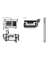
Specifications
52
Specifications
Housing
ND 720/ND 760
Bench-top design, cast-metal housing
Dimensions (W • H • D)
270 mm • 172 mm • 93 mm
Oper. temperature
0° to 45° C (32° to 113° F)
Storage temperature –20° to 70° C (–4° to 158° F)
Encoder inputs
For encoders with 7 to 16 µAPP
Grating period 2, 4, 10, 20, 40,
100, 200 µm and 12.8 mm
Refe rence mark evaluation for
distance-coded and single
reference marks
Input frequency
Max. 100 kHz for 30 m (98.5 ft)
cable length
Weight
Approx. 2.3 kg (5 lb)
Relative humidity
<75% annual average
<90% in rare cases
Display step
Adjustable
(see “Linear Encoders”)
Power supply
90 Vac to 260 Vac (−15% to +10%)
48 Hz to 62 Hz
Datums
2 (nonvolatile)
Functions
Power consumption
15 W
Protection
IP 40 as per IEC 529
− Tool radius compensation
− Distance-to-go display
− Probing functions
− Circular & linear hole patterns
− Scaling factor
− Measured value output
RS-232/V.24
Interface
Baud rates adjustable
110, 150, 300, 600, 1200, 2400,
4800, 9600, 19 200, 38 400
20°
8
.32"
4.
.18 5
"
15
.6"
4.
.18 5
"
92
3.622"
120 + 0.5
4.73 + .02"
38 ± 0.5
1.5 ± .02"
Specifications
Tilting base
56
2.205"
Dimensions in mm/inches
210 ± 0.2
8.268 ± .008"
240
9.45"
53
DR. JOHANNES HEIDENHAIN GmbH
Dr.-Johannes-Heidenhain-Straße 5
83301 Traunreut, Germany
{ + 49 / 86 69 / 31-0
| + 49 / 86 69 / 50 61
e-mail: [email protected]
{ Service
+ 49 / 86 69 / 31-12 72
{ TNC-Service + 49 / 86 69 / 31-14 46
| + 49 / 86 69 / 98 99
e-mail: [email protected]
http://www.heidenhain.de
54
341 696-21 . SW AA00 . 5 . 6/99 . F&W . Printed in Germany . Subject to change without notice