1
INTREPID User Manual
Library | Help | Top
Radiometrics theoretical background (R25)
1
| Back |
Radiometrics theoretical background (R25)
Top
Multi-channel spectra processing performs the following operations on multi-channel
airborne radiometric data:
•
Spectral noise cleaning
•
Live time/Dead time correction
•
Energy calibration (correction for photo-peak drift)
•
Aircraft, cosmic and radon background correction
Once the spectra have been successfully adjusted, standard potassium, uranium,
thorium and total count window data are extracted by integrating each spectrum over
the appropriate energy range.
Live/Dead time—introduction
The dead time of a gamma ray spectrometer is effectively the time taken by the
equipment to analyse a single gamma ray; during this period the equipment is busy
and cannot analyse any other gamma rays. You can calculate the true count N from
the measured count n if the dead time T is known, using the approximation:
N = n/(1–nT)
You can measure the dead time for your spectrometer empirically.
The live time of a gamma ray spectrometer is the time in a given time interval that
the spectrometer is available to accept data. The live time, L will normally be related
to the dead time (T) by the formula
L = 1 – nT
In some systems there may be factors other than the count rate contributing to a
reduction in the live time. For example, housekeeping functions such as on-line
energy calibration may cause the spectrometer to be unavailable for a short period.
Dead time correction for systems with these features is not accurate enough. Such
systems instead measure live time using the spectrometer and record it with the
spectral data (See "INTREPID 256 channel spectrum format" in Radiometrics—file
formats (R26)).
For systems using live time, the true count is given by
N = n/L
INTREPID can perform either dead or live time corrections.
Your spectrometer may behave differently for data in the cosmic channel (3–6 MeV),
so you may wish to perform dead time correction in the cosmic channel differently, or
omit it. INTREPID provides a facility for this. See Cosmic background corrections
for details about the cosmic background correction.
Library | Help | Top
© 2012 Intrepid Geophysics
| Back |
INTREPID User Manual
Library | Help | Top
Radiometrics theoretical background (R25)
2
| Back |
Energy calibration—introduction
INTREPID has a standard set of spectrum data with peaks and troughs typical of the
radiometric data you have produced. The standard spectrum depends on the aircraft
and the spectrometer. You must determine them empirically for the spectrometer
and aircraft that you are using. Count rate peaks and troughs occur at energies that
you can use as 'landmarks' for checking the measured energies of your data. It
compares your data with this standard to check and adjust the accuracy of the
energies reported by your spectrometer. INTREPID 'superimposes' your data on the
standard spectrum and looks for the landmark peaks and troughs. If your landmarks
occur at a different energy, INTREPID will adjust your reported energy range to
conform with the standard spectrum. In this way INTREPID calibrates your
spectrometer.
Rather than process the whole spectrum, you can examine a number of energy ranges
which contain the best landmarks for the calibration process. These are called
energy windows.
You can specify the energy windows directly or use the default set provided by
INTREPID.
INTREPID performs the calibration process one traverse line at a time. It integrates
the spectra for the line and aligns the data in the energy windows with that of the
standard spectrum. INTREPID calculates the calibration (the corrected high and low
bounds for the whole spectrum) for the whole traverse line and then updates all of the
individual spectra in the line using this calibration.
You can find a full description of this energy calibration technique in Minty et al1.
The technique involves iteratively adjusting the energy bounds of the spectrum using
double quadratic minimisation. It does not alter any of the count rates
To ensure that the quadratic minimisation converges, the initial estimation for the
energy bounds must be fairly close to the true values. You must specify a nominal
spectra energy range for this initial estimation.
1. Minty, B. R. S., Morse, M. P., and Richardson, L.M., 1990, Portable calibration sources
for airborne gamma-ray spectrometers: Expl. Geophys., 21.
Library | Help | Top
© 2012 Intrepid Geophysics
| Back |
INTREPID User Manual
Library | Help | Top
Radiometrics theoretical background (R25)
3
| Back |
Background corrections—introduction
Radiation not originating from the ground is regarded as background. The
background corrections are by far the largest and most difficult correction to make.
There are three main sources of background radiation:
•
radioactivity due to the aircraft and its contents
•
cosmic radiation
•
atmospheric radon (222Rn) and its daughter products.
Radon, cosmic and aircraft background radiation all originate in the atmosphere and
in the aircraft and its equipment. The shapes of these spectra are determined from
calibration of the airborne acquisition system. Calibration is achieved using a series of
test flights. The data from these calibrations is used to compute the various
coefficients or spectra which are required to perform the radiometric corrections.
Aircraft background radiation is due to the contamination of the aircraft structure
and equipment and the detector itself.
Primary cosmic radiation from outside our solar system and from the sun reacts with
atoms and molecules in the upper atmosphere and generates a complex secondary
radiation. This radiation reacts with the air, aircraft and detector to produce the
cosmic gamma-ray background.
Atmospheric 222Rn and its daughter products—specifically 214Bi and 214Pb, are the
major contributors to the background. 222Rn is very mobile and can escape into the
atmosphere from soils and rock fissures in response to the 'pumping' action of
changing temperatures and pressures. Its daughter products 214Bi and 214Pb attach
to airborne aerosols and dust particles and their distribution is thus a function of air
movements and wind patterns.
Aircraft background corrections
The aircraft background radiation spectrum is constant. It can be performed either
as a full spectrum correction before photo-peak extraction or as a window correction
after photo-peak extraction.
Cosmic background corrections
In the lower atmosphere this radiation has a constant energy distribution, but it
decreases in amplitude with decreasing altitude. The amplitude of the cosmic
spectrum is linearly related to the count rate in the 3–6 MeV range, the so called
cosmic channel. If you know the cosmic spectrum corresponding to a cosmic channel
base count rate, you can use the cosmic channel count rate for each spectrum to
calculate the cosmic background spectrum and subtract it from the spectrum.
Since the cosmic channel has an energy range outside that of the spectral data you
wish to use, you may have different arrangements for collecting this data, or your
spectrometer may behave differently in the 3–6 MeV range. You may therefore wish
to calculate the dead time for the cosmic channel differently. INTREPID has a
facility for independent dead time correction in the cosmic channel. See Live/Dead
time—introduction for more information about dead time correction.
You can perform cosmic background correction either as a full spectrum correction
before photo-peak extraction or as a window correction after photo-peak extraction.
Library | Help | Top
© 2012 Intrepid Geophysics
| Back |
INTREPID User Manual
Library | Help | Top
Radiometrics theoretical background (R25)
4
| Back |
Radon background estimation
You can estimate the radon background with the full spectrum analysis technique
known as the spectral ratio method.
For gamma-ray counts above the Compton continuum, the low energy 214Bi
photopeak at 0.609 MeV for atmospheric radiation suffers far less attenuation
relative to the 214Bi peak at 1.76 MeV than is the case for radiation from uranium in
the ground. Since thorium and potassium sources do not contribute appreciably to
these peak count rates, you can use them to estimate the contributions of radon and
uranium to the observed spectrum.
Before performing the radon background estimation, you must adjust the spectra for
dead time (See Live/Dead time—introduction), energy calibrate them (See Energy
calibration—introduction) and remove the cosmic and aircraft background
components (See immediately above).
Minty et al1 used portable calibration sources to measure pure U, Th and K spectra
over a range of altitudes, and Minty and Richardson2 derived aircraft and cosmic
spectra for the AGSO system from high-altitude calibration flights. You can derive
the radon spectrum from calibration flights at survey altitude over water and in the
presence of radon.
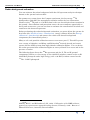
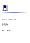
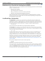
The following figure shows the 222Rn spectrum and the U, Th and K spectral
components relative to a low energy (0.54–0.68 MeV) window centred on the 214Bi
0.609 MeV photopeak and a high energy (1.65–1.96 MeV) window centred on the
214Bi
1.76 MeV photopeak.
1. ibid
2.Minty, B.R.S., and Richardson, L.M., 1989 - Calibration of the BMR airborne
gamma-ray spectrometers upward-looking detector, February, 1989. Bureau of
Mineral Resources, Australia, Record 1989/8.
Library | Help | Top
© 2012 Intrepid Geophysics
| Back |
INTREPID User Manual
Library | Help | Top
Radiometrics theoretical background (R25)
5
| Back |
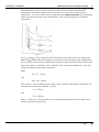
The important feature of these windows is that only the radon and uranium
components contribute significantly to gamma-ray counts above the Compton
continuum. You can estimate these count rates (the peak count rates) by integrating
under each peak but above the straight lines used to approximate the Compton
continuum.
Let Lob and Hob be the respective observed peak count rates in the low energy and
high energy peaks after correcting the spectrum for aircraft and cosmic background.
Let Lr and Hr be the radon contribution to the low energy and high energy peak count
rates respectively. Similarly, let Lu and Hu be the uranium contribution to the low
energy and high energy peak count rates.
Then
Lob = Lr + Lu(1)
and
Hob = Hr + Hu(2)
Also, since we can assume that the shape of the uranium and radon components are
constant for a particular altitude, we have
Lr = c1Hr(3)
and
Lu = c2Hu(4)
where c1 and c2 are constants that can be determined directly from the radon and
uranium spectra, respectively.
Library | Help | Top
© 2012 Intrepid Geophysics
| Back |
INTREPID User Manual
Library | Help | Top
Radiometrics theoretical background (R25)
6
| Back |
Equations 1 to 4 give
Lr = (Lob–c2Hob) / (1+c2/c1) (5)
You can then use the value of Lr with the radon calibration spectrum to calculate the
radon background spectrum correction, and subtract it from the observed spectra.
It is most important to correctly perform the energy calibration of the spectra. The
Bi214 0.609 MeV photopeak is relatively narrow and you need to energy calibrate the
observed spectra to a high degree of precision.
To obtain sufficiently good statistics to calculate the radon background, INTREPID
sums the spectra over a defined interval (default 100 readings). It then uses
Equation 5 to calculate the amplitude of the radon background spectrum and
subtracts it from each individual spectrum over the summed interval. INTREPID
repeats the procedure until it reaches the end of the line.
For the purposes of radon background estimation you can specify energy windows
surrounding the 214Bi 0.609 MeV and 1.76 MeV photopeaks. INTREPID 's default
Radon background calculation intervals are 0.54–0.68 MeV for the 'low' energy ('L')
window and 1.65–1.96 MeV for the 'high' energy ('H') window.
INTREPID also supports radon removal using the older upward looking detector
method.
Standard 3 (K U Th) channel data generation—introduction
After you have performed the corrections and calibration on the multichannel data,
you can extract the potassium, thorium and uranium count rates. The count rate for
each element is found by integrating (summing) the counts over a defined energy
range, or window. The International Atomic Energy Agency (IAEA) recommends the
following energy windows for the three elements:
Potassium
1.370–1.570 MeV
Uranium
1.660–1.860 MeV
Thorium
2.410–2.810 MeV
Using this method for each spectrum (i.e., each integration period / data point) you
can produce a complete set of K, Th and U data for your survey.
The calibration spectra
To carry out these adjustments on multi-channel spectra, you need to derive a set of
calibration spectra empirically from the aircraft and spectrometer that you are using.
The calibration spectra set must consist of five individual spectra, all 256 channel and
encompassing the energy bounds of the spectrometer you are using, normally 0.0–3.0
MeV. The five required calibration spectra are as follows:
Aircraft the aircraft background spectrum in counts/100 seconds.
Cosmic the cosmic spectrum corresponding to a count rate of 100 counts/second in
the 3–6 MeV cosmic channel.
Standard a typical spectrum at the nominal survey altitude.
Radon a typical spectrum due to Radon at the nominal survey altitude.
Library | Help | Top
© 2012 Intrepid Geophysics
| Back |
INTREPID User Manual
Library | Help | Top
Radiometrics theoretical background (R25)
7
| Back |
Uranium the spectrum due to uranium from the ground at the nominal survey
altitude.
INTREPID only uses the shape of the Standard, Radon and Uranium calibration
spectra, so the actual count rates for these spectra in the calibration spectra file are
immaterial.
The calibration spectra file must be in ASCII format and have the extension .asc
INTREPID will ignore blank lines and lines starting with #. We have included an
abbreviated sample calibration spectra file in this manual (See "Example of
calibration spectra file" in Radiometrics—file formats (R26)). You can use this as a
model for creating your own file. INTREPID also has a library of example
calibration spectra files in the config/calibration_spectra dir. You can use
these pre-existing calibrations files if you cannot derive them for your own data.
Standard 3 corrections theory
The elements Potassium (K), Uranium (U) and Thorium (Th) emit gamma rays.
These elements occur in most rocks and soils. The gamma rays are of different
energies which you can detect using a differential spectrometer. You can process and
analyse this data to provide information about the abundances of the three elements
in the rock or soil.
Gamma rays are attenuated by rock and overburden. As a result, approximately 90%
of the radiation comes from the top 150 to 200 mm of rock (or 300 to 400 mm of soil
cover). Gamma rays are also attenuated by the air between the source and the
aircraft. The radiation is reduced by half in passing through each 100 to 130 metres
of air.
Compton scattering in the source, air and the detector modifies the energy
distribution of the gamma-rays.
The spectrometer in the aircraft also measures a fairly constant background
radiation level which is due to sources other than the ground (cosmic, aircraft and
atmospheric radon gas). See Multi-channel gamma ray spectrometric processing
(C07) for a full discussion of background radiation, dead time and spectrum
calibration corrections, as well as calculation of the Potassium, Uranium, Thorium
and Total Count data.
We wish to remove the effects of height attenuation and Compton scattering, and end
up with count rates in the Potassium, Uranium and Thorium channels which are
directly proportional to the abundance of the three elements at the Earth's surface.
The S3GSC process performs the height correction and Compton scattering correction
(often called 'stripping' or 'energy stripping') of the Potassium, Uranium, Thorium
and Total Count data.
Library | Help | Top
© 2012 Intrepid Geophysics
| Back |
INTREPID User Manual
Library | Help | Top
Radiometrics theoretical background (R25)
8
| Back |
Compton scattering correction (stripping)—theory
Compton scattering contributes to the uranium and potassium count rates. Scattered
thorium radiation contributes counts to the lower energy uranium and potassium
channels. Scattered uranium contributes to the potassium channel only. The
coefficients for correction depend on altitude, the window widths employed, size,
number and spacing of radiation detectors, etc. Our stripping equations are as
follows:
NcTh = NTh
NcU = NU – α.NTh
NcK = NK – β.NcTh – γ.NcU(1)
where1
Np is the measured count rate for element p
Ncp is the corrected count rate for element p
α, β, γ are stripping ratios:
α = mαh + cα
β = mβh + cβ
γ = mγh + cγ
where
mx = slope (change per metre) of ratio x
cx = ground level value of ratio x
h = measured clearance (height above ground)
Height correction theory
It is in practice impossible for an aircraft to maintain a constant ground clearance. At
different heights radiation from the ground suffers different attenuations due to
variations in the mass of air it has to pass through. It is easier to compare data
within a survey if you adjust them to a standard distance above ground level. You
would typically use the nominal terrain clearance of your aircraft as this standard
distance.
In theory you might consider the geometry of the source whilst calculating this height
correction, in order to use a more complex attenuation formula. In practice, the
simpler process of applying a uniform exponential correction provides a satisfactory
height correction, as long as the ground clearance varies within reasonable limits.
1. For the AGSO system
α = .000518 h + 0.45500
β = .000804 h + 0.44100
γ = .000976 h + 0.80500
Library | Help | Top
© 2012 Intrepid Geophysics
| Back |
INTREPID User Manual
Library | Help | Top
Radiometrics theoretical background (R25)
9
| Back |
Our correction is based on the formula:
N0 = Ne–u(H–h)(2)
where1
N0 = height-corrected count
N = height-uncorrected count (Nc from the stripping correction (See Compton
scattering correction (stripping)—theory)
h = height above ground (measured and corrected for temperature and pressure if
possible (see below))
H = nominal flying height
u = attenuation coefficient (different for each energy of the gamma-rays—uK, uU, uTh)
The attenuation of the gamma rays with height in reality relates to the mass of the
column of air below the aircraft. This depends on the air pressure and temperature.
If air temperature and pressure data are available then you can adjust the measured
height of the aircraft above ground level for fluctuations in temperature and pressure.
We use the formula
( t0 p1 hm )
h = -------------------------( t1 + t0 ) p0
where
h = effective height
hm = measured height
t0 = 273.15
p0 = 1013.25
t1 = measured temperature (degrees C)
p1 = measured air pressure (millibars)
In practice the exponential attenuation correction for height does not yield
meaningful results for data which is collected above about 250 metres. It is common
practise to ignore data obtained from heights above this level.
1. For AGSO's system, current values of u are:
for total count (integral) u = 0.006560
for potassium u = 0.007550
for uranium u = 0.005570
for thorium u = 0.005570
Library | Help | Top
© 2012 Intrepid Geophysics
| Back |
INTREPID User Manual
Library | Help | Top
Radiometrics theoretical background (R25)
10
| Back |
Sensitivity conversions—theory
If you make traverses over a test strip of known ground concentrations in potassium,
uranium and thorium, and compare your spectrometer data with the known
concentrations, you can establish a relationship between the count rates recorded by
your spectrometer and the actual ground concentrations. You can thus establish the
sensitivity of the gamma ray spectrometer in terms of counts per unit concentration
per unit time. You can use this sensitivity to scale the corrected radiometric count
rate data to give ground concentrations. This provides a degree of data independence
from survey parameters such as crystal volume and survey flying height.
The best estimates for K, U, and Th are obtained using spectral smoothing (NASVD/
MNF) followed by conventional 3-channel processing.
It is standard practice to report total count in units of nGy/h (the equivalent air-absorbed
dose rate at 1m above the ground).
Library | Help | Top
© 2012 Intrepid Geophysics
| Back |