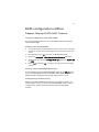
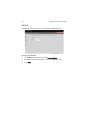
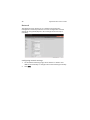
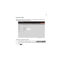
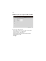
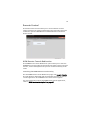
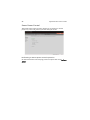
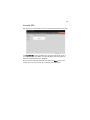
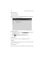
1
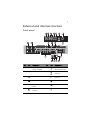
AR585 Series
User Guide
© 2010. All Rights Reserved.
Acer AR585 Series
User Guide
Acer AR585
Model Number :
Serial Number:
Purchase Date:
Place of Purchase:
iii
Information for your safety and
comfort
Safety instructions
Read these instructions carefully. Keep this document for future reference.
Follow all warnings and instructions marked on the product.
Turning the product off before cleaning
Unplug this product from the wall outlet before cleaning. Do not use liquid
cleaners or aerosol cleaners. Use a damp cloth for cleaning.
CAUTION for plug as disconnecting device
Observe the following guidelines when connecting and disconnecting power to
the power supply unit:
•
Install the power supply unit before connecting the power cord to the AC
power outlet.
•
Unplug the power cord before removing the power supply unit from the
computer.
•
If the system has multiple sources of power, disconnect power from the
system by unplugging all power cords from the power supplies.
CAUTION for accessibility
Be sure that the power outlet you plug the power cord into is easily accessible
and located as close to the equipment operator as possible. When you need to
disconnect power to the equipment, be sure to unplug the power cord from the
electrical outlet.
Warnings
•
Do not use this product near water.
•
Do not place this product on an unstable cart, stand or table. If the product
falls, it could be seriously damaged.
•
Slots and openings are provided for ventilation to ensure reliable
operation of the product and to protect it from overheating. These
openings must not be blocked or covered. The openings should never be
blocked by placing the product on a bed, sofa, rug or other similar surface.
This product should never be placed near or over a radiator or heat
register, or in a built-in installation unless proper ventilation is provided.
iv
•
Never push objects of any kind into this product through cabinet slots as
they may touch dangerous voltage points or short-out parts that could
result in a fire or electric shock. Never spill liquid of any kind onto or into
the product.
•
To avoid damage of internal components and to prevent battery leakage,
do not place the product on a vibrating surface.
•
Never use this product under sporting, exercising, or any vibrating
environment which will probably cause unexpected short current or
damage rotor devices, hard drives, optical drives, and even exposure risk
from lithium battery pack.
•
This product is not suitable for use with visual display workplace devices
according to B2 of the German Ordinance for Work with Visual Display
Units.
Using electrical power
•
This product should be operated from the type of power indicated on the
marking label. If you are not sure of the type of power available, consult
your dealer or local power company.
•
Do not allow anything to rest on the power cord. Do not locate this
product where people will walk on the cord.
•
If an extension cord is used with this product, make sure that the total
ampere rating of the equipment plugged into the extension cord does not
exceed the extension cord ampere rating. Also, make sure that the total
rating of all products plugged into the wall outlet does not exceed the fuse
rating.
•
Do not overload a power outlet, strip or receptacle by plugging in too
many devices. The overall system load must not exceed 80% of the branch
circuit rating. If a power strip is used, the load should not exceed 80% of
the power strip's input rating.
•
This product's power supply is equipped with a three-wire grounded plug.
The plug only fits in a grounded power outlet. Make sure the power outlet
is properly grounded before inserting the power supply plug. Do not insert
the plug into a non-grounded power outlet. Contact your electrician for
details.
Warning! The grounding pin is a safety feature. Using a power outlet that is
not properly grounded may result in electric shock and/or injury.
Note: The grounding pin also provides good protection from unexpected
noise produced by other nearby electrical devices that may interfere with
the performance of this product.
v
•
Use the product only with the supplied power supply cord set. If you need
to replace the power cord set, make sure that the new power cord meets
the following requirements: detachable type, UL listed/CSA certified, VDE
approved or its equivalent, 4.6 meters (15 feet) maximum length.
Product servicing
Do not attempt to service this product yourself, as opening or removing covers
may expose you to dangerous voltage points or other risks. Refer all servicing to
qualified service personnel.
Unplug this product from the wall outlet and refer servicing to qualified service
personnel when:
•
the power cord or plug is damaged, cut or frayed
•
liquid was spilled into the product
•
the product was exposed to rain or water
•
the product has been dropped or the case has been damaged
•
the product exhibits a distinct change in performance, indicating a need
for service
•
the product does not operate normally after following the operating
instructions
Note: Adjust only those controls that are covered by the operating instructions,
since improper adjustment of other controls may result in damage and will often
require extensive work by a qualified technician to restore the product to normal
condition.
This server should be located in a restricted access location or an area with similar
instruction.
Caution: Danger of explosion if battery is incorrectly replaced. Replace only
with the same or equivalent type recommended by the manufacturer. Dispose of
used batteries according to the manufacturer's instructions.
Caution: Use only a UL approved Laser Class I optical fiber transceiver with this
server. When an optical transceiver is used, a barrier should be provided to
cover the openings on the transceiver.
vi
Disposal instructions
Do not throw this electronic device into the trash when discarding.
To minimize pollution and ensure utmost protection of the global
environment, please recycle. For more information on the Waste
from Electrical and Electronics Equipment (WEEE) regulations, visit
www.acer-group.com/public/Sustainability/sustainability01.htm.
vii
Regulations and safety notices
FCC notice
This device has been tested and found to comply with the limits for a Class A
digital device pursuant to Part 15 of the FCC rules. These limits are designed to
provide reasonable protection against harmful interference in a residential
installation. This device generates, uses, and can radiate radio frequency energy
and, if not installed and used in accordance with the instructions, may cause
harmful interference to radio communications.
However, there is no guarantee that interference will not occur in a particular
installation. If this device does cause harmful interference to radio or television
reception, which can be determined by turning the device off and on, the user
is encouraged to try to correct the interference by one or more of the following
measures:
•
Reorient or relocate the receiving antenna.
•
Increase the separation between the device and receiver.
•
Connect the device into an outlet on a circuit different from that to which
the receiver is connected.
•
Consult the dealer or an experienced radio/television technician for help.
Notice: Shielded cables
All connections to other computing devices must be made using shielded cables
to maintain compliance with FCC regulations. In compliance with FCC
regulations, use shielded cables to connect to other computing devices. A
dual-link cable is recommended for DVI output.
Notice: Peripheral devices
Only peripherals (input/output devices, terminals, printers, etc.) certified to
comply with the Class A limits may be attached to this equipment. Operation
with non-certified peripherals is likely to result in interference to radio and TV
reception.
Caution
Changes or modifications not expressly approved by the manufacturer could
void the user's authority, which is granted by the Federal Communications
Commission, to operate this computer.
viii
Operation conditions
This device complies with Part 15 of the FCC Rules. Operation is subject to the
following two conditions: (1) this device may not cause harmful interference,
and (2) this device must accept any interference received, including interference
that may cause undesired operation.
Notice: Canadian users
This Class A digital apparatus complies with Canadian ICES-003.
Remarque à l'intention des utilisateurs canadiens
Cet appareil numérique de la classe B est conforme a la norme NMB-003 du
Canada.
Compliant with Russian regulatory certification
Notice: BSMI
Laser compliance statement
The CD or DVD drive used with this computer is a laser product. The CD or DVD
drive's classification label (shown below) is located on the drive.
CLASS 1 LASER PRODUCT
CAUTION: INVISIBLE LASER RADIATION WHEN OPEN. AVOID EXPOSURE TO
BEAM.
Appareil à laser de classe 1
Attention : Radiation laser visible et invisible en cas d’ouverture. Éviter toute
exposition aux rayons.
Laserprodukt der Klasse 1
Achtung: Beim Öffnen werden unsichtbare Laserstrahlen freigelegt. Setzen Sie
sich diesen Strahlen nicht aus.
Prodotto laser di classe 1
Attenzione: Radiazioni laser invisibili in caso d’apertura. Evitare l’esposizione ai
raggi.
ix
Producto láser de Clase 1
Precaución: Cuando está abierta, hay radiación láser. Evite una exposición al haz
de luz.
Produto Laser de Classe 1
Precaução: Radiação laser invisível quando aberto. Evite exposição ao feixe.
Laserproduct klasse 1
Voorzichtig: Onzichtbare laserstraling indien geopend. Voorkom blootstelling
aan straal.
Declaration of Conformity for EU countries
Hereby, Acer, declares that this system is in compliance with the essential
requirements and other relevant provisions of Directive 1999/5/EC.
List of applicable countries
This device must be used in strict accordance with the regulations and
constraints in the country of use. For further information, please contact local
office in the country of use. Please see http://ec.europa.eu/enterprise/rtte/
implem.htm for the latest country list.
x
1 System tour
System notes
External and internal structure
Front panel
Rear panel
Internal components
Mainboard layout
Mainboard jumper settings
Appendix A Server management tools
Server management overview
RAID configuration utilities
Adaptec Onboard SATA RAID Creation
MegaRAID 9260-8I SAS RAID Creation
Appendix B Acer Smart Console
Using Acer Smart Console
Software requirements
Accessing Acer Smart Console
Acer Smart Console user interface
System Information
Server Health
Configuration
Remote Control
Launch SOL
Virtual Media
Maintenance
KVM function description
Exit
Index
iii
vii
1
2
3
3
6
8
9
12
15
16
17
17
19
21
22
23
23
24
24
25
28
41
43
44
46
47
53
55
Contents
Information for your safety and comfort
Regulations and safety notices
xii
1 System tour
2
1 System tour
System notes
The AR585 is an outstanding 2U rack-mountable server that runs on
the AMD Opteron™ 6000 Series server platform. The following AMD
technologies are supported in this platform: AMD CoolCore™, AMD
PowerNow!™, Enhanced C1 state, AMD CoolSpeed, and APML (in
APML enabled platforms).
The AR585 targets small and medium businesses that require server
solution combined with performance, reliability and expandability.
AR585 is a flexible and high reliability rack server that satisfies growing
businesses and customers’ needs.
System features and support
•
Four G34 CPU sockets supporting the AMD Opteron™ 6000 Series
processors
•
AMD Embedded Enterprise Chipset (SR5690/SR5670 I/O bridge +
SP5100 south bridge)
•
32 quad channel DDR3 slots supporting up to 512 GB of RDDR3
modules or 128 GB of UDDR3 modules
•
Support for high speed peripherals using PCI Express Generation 2
technology (two PCIe x16 slots, one PCIe x8 slot, and choice of one
PCIe x8 or one Flex I/O slot)
•
Additional I/O option using one Universal I/O (UIO) expansion slot
•
HyperTransport™ 3 Technology allows high speed interconnection
between the processors and the I/O devices
•
Supports up to six 3.5-inch SAS/SATA hard disk drives
•
One DVD-ROM optical drive
•
I/O ports supported
•
•
Four USB ports (two each on the front and rear panels)
•
Two serial ports (one each on the front and rear panels)
•
One video port (VGA)
•
Two Gigabit LAN ports
•
One dedicated IPMI LAN port
•
One PS/2 mouse port, one PS/2 keyboard port
One 1400 W power supply unit (PSU), support for redundant PSU
3
External and internal structure
Front panel
No.
Icon
Component
No.
Icon
Component
1
Default power
supply unit (PSU)
7
Overheating/fan
failure LED indicator
2
Redundant PSU bay
8
LAN port 1/2 activity
indicators
3
USB 2.0 ports
9
HDD activity
indicator
4
Serial port
10
Power indicator
5
Optical disc drive
(ODD)
11
Reset button
6
Power failure LED
indicator
12
Power button
4
No.
1 System tour
Icon
Component
No.
Icon
Component
13
3.5-inch hard disk
drive (HDD) bays
16
HDD release button
14
HDD access/failure
LED indicator
17
HDD security lock
15
HDD rebuild/spare
LED indicator
18
2.5-inch hard disk
drives
Control panel LED indicator status
No.
Function
1
2
Icon
Status
Indicated behavior
Power
failure
Red - On
Power supply unit failure
Overheating
/fan failure
Red - On
System temperature
safety threshold breach
Red - Blinking
System fan failure
3
LAN port 1/2
activity
Green - Blinking
Network activity on LAN
port 1 or 2
4
HDD activity
Amber - Blinking
Hard drive activity
5
Power state
Green - On
System is powered on
5
Hot-plug HDD carrier LED indicator status
Hard drive status
Hard drive access
Green - Blinking
Off
Hard drive failure
Green - On for SAS HDD,
Off for SATA HDD
Red - On
Hard drive rebuilding
Green - Blinking
Red - Blinking
HDD hot spare
Green - Blinking
Red - Blinking
6
1 System tour
Rear panel
No.
Icon
Component
No.
Icon
Component
1
PS/2 mouse port
8
Expansion slot covers
2
PS/2 keyboard port
9
AC power plug for
the redundant PSU
3
Dedicated IPMI LAN
port (10/100)
10
AC power plug for
the default PSU
4
USB 2.0 ports
11
Gigabit LAN port link
indicator
5
Serial port
12
Gigabit LAN port
activity indicator
6
Video port (VGA)
13
IPMI LAN port
activity indicator
7
Gigabit LAN ports
14
IPMI LAN port link
indicator
7
Rear panel LED indicator status
No.
Function
Status
Indicated behavior
1
IPMI LAN port link
Green
100 Mbps network link
Off
10 Mbps network link
2
IPMI LAN port
activity
Amber - Blinking
Active connection
3
Gigabit LAN port
activity
Yellow - On
Active connection
Yellow - Blinking
Transmit/receive activity
Off
10 Mbps network link
Green
100 Mbps network link
Amber
1000 Mbps network link
4
Gigabit LAN port
link
8
1 System tour
Internal components
No.
Component
1
HDD backplane board
2
Default PSU
3
Mainboard
4
Air shroud
5
System fans
9
Mainboard layout
No.
Code
Component
1
DP1
IPMI heartbeat LED
2
PCI-E slot1
PCIe Gen 2 x8 expansion slot
3
PCI-E slot2
PCIe Gen 2 x16 expansion slot
4
PCI-E slot3
PCIe Gen 2 x8 expansion slot
5
PCI-E slot4
PCIe Gen 2 x16 expansion slot
6
CPU1
Processor 1 socket
7
ID
Unit identifier button
8
FAN9
Processor 1 fan
9
LAN2
Gigabit Ethernet port 2
10
1 System tour
No.
Code
Component
10
LAN1
Gigabit Ethernet port 1
11
FAN8
Chassis fan 8
12
VGA
Video port
13
P1 DIMM
DDR3 DIMM slots for processor 1
14
COM1
Serial port 1
15
IPMI/LAN/USB0/USB1
Dedicated IPMI LAN port/rear USB ports
16
Keyboard/Mouse
PS/2 keyboard and mouse ports
17
CPU3
Processor 3 socket
18
FAN7
Processor 3 fan
19
P3 DIMM
DDR3 DIMM slots for processor 3
20
FAN1
Processor 4 fan
21
JF1
Front panel board connector
22
CPU4
Processor 4 socket
23
P4 DIMM
DDR3 DIMM slots for processor 4
24
FAN2
Chassis fan 2
25
FAN3
Chassis fan 3
26
FAN4
Processor 2 fan
27
CPU2
Processor 2 socket
28
P2 DIMM
DDR3 DIMM slots for processor 2
29
FAN5
Chassis fan 5
30
FAN6
Chassis fan 6
31
JPW1
24-pin main ATX power connector
32
JPW4
+12V 8-pin power connector
11
No.
Code
Component
33
JPW2
+12V 8-pin power connector
34
JPW3
+12V 8-pin power connector
35
JOH1
Overheating warning header
36
JPI2C1
Power I2C header
37
DP3
Mainboard power-on LED
38
T-SGPIO1
Serial general purpose I/O header for
SATA
39
T-SGPIO2
Serial general purpose I/O header for
SATA
40
SATA0-SATA5
SATA connectors
41
USB4/5 header
USB header 4/5
42
USB2/3 header
USB header 2/3
43
USB6
USB Type A port
44
JTPM1
Trusted platform module header
45
JBT1 Battery
CMOS battery
46
COM2
Serial port 2
47
JL1
Chassis intrusion header
48
JBT1
Clear CMOS jumper
49
UIO slot
UIO or PCIe Gen 2 x8 expansion slot
50
JPB1
BMC jumper
51
JPG1
VGA jumper
52
JWD1
Watchdog jumper
53
JSMB1
SMB header
54
JPL1
LAN port jumper
12
1 System tour
Mainboard jumper settings
No.
Code
Function
Setting
1
JPL1
Enable Gigabit
LAN ports
1-2 Close: Enabled (default setting)
2
JWD1
Enable watchdog
2-3 Close: Disabled
1-2 Close: Reset (default setting)
2-3 Close: NMI
Open: Disabled
3
JPG1
Enable VGA port
1-2 Close: Enabled (default setting)
2-3 Close: Disabled
4
JPB1
Enable BMC
1-2 Close: Enabled
2-3 Close: Normal (default setting)
5
JBT1
Clear CMOS
To clear CMOS, use a metal object
such as a small screwdriver to touch
both pads at the same time to
short the connection.
13
Mainboard LED
No.
Code
Function
Status
Description
1
DP1
IPMI heartbeat
Flashing green
BMC normal
2
DP3
Mainboard power
Green
Power on
14
1 System tour
Appendix A
Server management
tools
16
Appendix A Server management tools
Server management overview
The server management tools supported by this system are listed in the
table below.
Tool
Function
Acer Smart Server
Manager
Remotely manage the server in a network
environment through a single management station.
For detailed instructions on how to install and use this
utility, please refer to the Acer Smart Server Manager
User Guide.
Acer Smart Setup
Allows you to install your choice of operating system
for the server, clone system to set up multiple
identical servers, set up BMC, and configure RAID for
the system hard drives. For detailed instructions on
this utility, please refer to the Acer Smart Setup Help
file.
Acer Smart Console
Remotely manage the server via a UPnP tool or a Web
browser. For detailed instructions on this utility,
please refer to "Appendix B Acer Smart Console" on
page 21.
17
RAID configuration utilities
Adaptec Onboard SATA RAID Creation
Configuring Adaptec onboard SATA RAID
This section briefly shows how to create RAID volume with Adaptec
onboard SATA RAID.
Enabling onboard SATA RAID
1
Turn on the server and the display monitor. If the server is already
turned on, please close all open applications and then restart the
server.
2
During POST, press <F2> to access the BIOS Setup Utility.
3
Select the Advanced > ATA Controller Configuration submenu.
4
Change the setting of the OnChip SATA Type field from Native IDE
to RAID.
5
Press <F10> and select Ok to save the setting and close the Setup
Utility.
Entering onboard SATA RAID BIOS Utility
To start Adaptec onboard SATA RAID BIOS Utility, press CTRL-A when
you see the RAID BIOS prompt during POST. After POST finished, the
Adaptec RAID Configuration Utility will display on the screen.
Loading Factory Default Setting
Adaptec onboard SATA RAID utility does not provide an option for
factory default setting. To reset onboard SATA RAID volume related
configurations, please delete the existing onboard SATA RAID
volumes.
18
Appendix A Server management tools
Creating a RAID Volume
1
Select Array Configuration Utility option.
2
Select Create Array.
The Select drives to create Array displayed.
3
Select desired hard drive disk and then press <Insert> to add it in
the Selected Drives area.
4
Press <Enter> to complete the selection.
5
Select Array Type.
6
Configure the array properties.
7
Press Done when finish.
8
Press <Y> when "Do you want to create an array? (Yes/No):"
displayed.
9
Press any key to continue.
10 Once the RAID volume is created, press <Esc> to exit.
Initialing a RAID Volume
During Adaptec onboard SATA RAID volume creation process, the
onboard SATA RAID volume will be automatically initiated once the
onboard SATA RAID volume has been created.
Assigning a Hot Spare Drive
A hot spare is a hard disk drive that automatically replaces any failed
drive in a RAID volume, and can subsequently be used to rebuild the
RAID volume.
1
2
Select Array Configuration Utility option.
Select Add/Delete Hotspare.
The Select drives to assign Spare displayed.
3
Select desired hard drive disk and then press <Insert> to add it in
the Assigned Hotspare drives area.
4
Press <Enter> to complete the selection.
5
Press <Y> when "Do you want to create a spare? (Yes/No):"
displayed.
6
Once a hot spare drive is created, press <Esc> to exit.
19
MegaRAID 9260-8I SAS RAID Creation
Configuring MegaRAID SAS 260-8I
This section briefly shows how to create RAID volume with MegaRAID
SAS 260-8I.
Entering RAID BIOS Utility
To enter the RAID BIOS Utility for MegaRAID SAS 260-8I, press <Ctrl> +
<H> when you see the RAID BIOS prompt during POST. After POST
finished, the Adapter Selection page will show on the screen. Click
Start to launch the Configuration menu.
Loading factory default setting
1
Select Adapter Properties from the Configuration menu.
The current adapter settings appear. Click Next to change the
setting.
2
Change the setting of Set Factory Defaults from No to Yes then
click Submit.
3
Press <Ctrl> + <Alt>+ <Del> to reboot the server.
Creating RAID Volume
1
Click Start to launch the Configuration menu.
2
Select Configuration Wizard.
3
Select Add Configuration (default) and click Next.
4
Select Custom Configuration (default) and click Next.
5
Hold the <Ctrl> key and select the drives that you want to add into
the array. After selecting the drives, click Add to Array.
6
Click Accept DG then Next.
7
Select the array you just created, click on Add to SPAN then Next.
8
Select the RAID level you want to use, create the logical volume by
specify the size at Select Size, then click Accept to create the
logical volume.
9
Click Next after creating the logical volume.
10 Click Accept then Yes to save the configuration.
20
Appendix A Server management tools
Initialing a RAID volume
1
After creating the logical volumes on all of the RAID volumes, click
Accept then Yes to save the configuration.
2
Click Yes to initialize the new logical drives.
You will see all the logical drives listed.
3
Click Home to go back to the Configuration menu.
Assigning a Hot Spare Drive
1
Select a free disk marked as UNCONF GOOD and listed under
Physical Drives.
2
Select Make Global Dedicated HSP or Make Dedicated HSP and
click Go.
3
Click Home to go back to the Configuration menu.
You will see the disk marked as Hotspare in pink and listed under
Physical Drives.
4
Reboot the server and install the operating system. Select Exit,
click Yes and press <Ctrl> + <Alt>+ <Del>.
Appendix B Acer
Smart Console
22
Appendix B Acer Smart Console
Using Acer Smart Console
Acer Smart Console has a user-friendly graphical user interface (GUI)
and a standard Internet browser. This article will help you become
familiar with the Acer Smart Console. Each function will be described
clearly.
Acer Smart Console offers:
System monitoring: Providing detailed information via a web UI,
including system information readings, system health overview, sensor
readings, and System Event Log readings. Green, amber and red
indicators give a clear system health overview and sensor readings to
help you to determine system status.
Remote system management: Via KVM/IP redirection lets you fully
control the system. You can remotely power on, off, reset system
through Acer Smart Console in-band or out-of-band. Acer Smart
Console implements media redirection for the CD/DVD ROM drive and
floppy drive. This feature enables remote installation of the operating
system or applications.
Notification: Via SNMP trap and email to inform a person or
management software when system status changes.
Platform neutrality: Acer Smart Console uses the standard HTTP
protocols. You can easily use a web browser to remotely manage
servers running different operating systems. Acer Smart Console also
provides cross-platform JAVA-based KVM redirection.
Security: SSL (Secured Socket Layer) and auto session time out ensure
higher security when using the web UI through HTTPS. When using
KVM and media redirection you can also encrypt the communication.
Account management: Acer Smart Console implements role-based
management. User accounts are separated into three levels: No access,
operator and administrator. Acer Smart Console also provides RADIUS
and LDAP Client Support.
23
Software requirements
Supported environments: Microsoft Windows Vista, XP, Windows 2000,
2003 and Server 2008.
JAVA: Version 6, update 12 or higher
Note: KVM Remote Console Redirection needs to run in a JAVA
environment. Ensure the JAVA Runtime Environment Tool is
installed.
Accessing Acer Smart Console
1
Open your web browser and enter the system’s IP address. You will
be prompted to enter a username and password.
2
Enter the root username and password in the login screen.
• Username: root
•
Password: superuser
3
Click Login. The Acer Smart Console page appears.
Note: The default username is root and the default password is
superuser. Both the username and password are case sensitive and
should be entered in lower case each time.
Important: Logging into the console allows you full administrative
rights. Once logged in, you should you change your password.
24
Appendix B Acer Smart Console
Acer Smart Console user interface
The Acer Smart Console page opens once you have logged in. This
page provides a central location for managing all connected servers.
The user interface includes a system status alert indicator, function list,
menu bar, function title, section information.
System status
The system status indicator, located in the upper left-hand corner of
the Acer Smart Console page, monitors and displays the system health
and stability. The system sensors allow you to monitor the system's
hardware parameters, such as fan performance, temperature sensors,
voltages, and power status. The following are the different system
health statuses that may be displayed on the console.
•
Normal: The system is in good health and no alerts were detected
on the sensors.
•
Warning: At least one sensor has a warning alert.
•
Critical: At least one sensor has a critical alert.
System Information
The System Information menu includes options that allow you to view
general system information and the system FRU (field replaceable
units). Selecting the System Information menu displays the system
information and FRU readings options in the left pane.
System Information
Displays general server information, such as the power status,
management network IP and management controller MAC address,
BMC firmware version and build time, FRU revision and SDR revision
and allows you to manage the chassis LED indicator.
FRU Reading
Provides information about major system components, including
chassis, main board and other product information.
25
Server Health
Displays data related to the server's health, such as sensor readings and
the event log. This menu has two options: Sensor Readings and Event
Log.
Sensor Readings
Allows you to monitor status of the voltages of the power supply, the
fan speed, processor and system temperature sensors.
Sensor Display Color
Indicates the health of the system processor, fan, temperature and
voltage in a box displayed before each sensor category.
•
Green: Indicates the system is in good health and no alerts were
detected on the sensors.
•
Amber: Indicates at least one sensor has a warning alert.
•
Red: Indicates at least on sensor has a critical alert.
26
Appendix B Acer Smart Console
Threshold
Click Show Thresholds to view the threshold parameters of each
sensor. It displays the Low Non-Critical (NC), High Non-Critical (NC),
High Critical Threshold (CT) threshold information, and these items can
not be modified. When each threshold matches alert level, system will
send the alert to the specified destinations. To configure the specified
destination, please go to Alert section. To refresh the sensor status, just
click Refresh.
27
Event Log
Provides a record of system events related to critical hardware
components. It logs the events when the sensor triggers an abnormal
state or is recovering from an abnormal state. When the log matches a
pre-defined alert, the system will send out a notification automatically
if pre-configured.
28
Appendix B Acer Smart Console
Configuration
Allows you to designate email recipients for notification of system
alerts, configure the Date and Time, configure the LDAP (Lightweight
Directory Access Protocol) and RADIUS settings, configure the mouse
mode settings, configure the network settings, configure the Dynamic
DNS, configure the remote session settings, configure the SMTP email
server settings, create an SSL certificate and manage users.
The Configuration menu has the following options:
•
Alerts
•
Date and Time
•
LDAP
•
RADIUS
•
Mouse mode
•
Network
•
Dynamic DNS
•
Remote Session
•
SMTP
•
SSL Certificate
•
Users
29
Alerts
Allows you to designate up to 15 email recipients for notification of
system alerts. When alerts occur, the system will send an email or a
SNMP (Simple Network Management Protocol) trap containing the
event detail to the designated recipients.
The Alerts page allows you to do the following:
•
Modify: Change the email address or the destination server.
•
Send Test Alert: Send a test alert to the designated email address.
•
Delete: Remove pre-set alert destination settings.
Setting up alerts
You can set up notifications to be sent via SNMP trap or via email.
Setting up SNMP traps
1
On the Alerts page click Modify.
2
Specify the event severity, such as Critical or Warning.
3
Enter the IP information.
4
Click Save.
30
Appendix B Acer Smart Console
Setting up email notifications
1
On the Alerts page click Modify.
2
Specify the event severity, such as Critical or Warning.
3
Enter the recipient's email address.
4
Enter a subject and message.
5
Click Save.
Date and Time
The Date and Time option allows you to set the BMC date and time.
31
LDAP (if available)
The LDAP option allows you to download the user account list and
authentication from the LDAP server and create Acer Smart Console
user accounts from this list.
Configuring LDAP settings
1
On the LDAP Settings page and check Enable LDAP
Authentication.
2
Enter the required information to access the LDAP server.
3
Click Save.
32
Appendix B Acer Smart Console
RADIUS
The RADIUS option allows you to configure the RADIUS option.
Configuring RADIUS
1
On the RADIUS Settings page check Enable RADIUS.
2
Enter the required information to access the RADIUS server.
3
Click Save.
33
Mouse mode
The Mouse mode option allows you to set a mouse mode to control
your mouse.
Setting the mouse mode
1
Select a mouse mode from the Mouse Mode page.
•
Absolute: Select this setting when using a Microsoft Windows
operating system.
•
Relative: Select this setting when using a Linux operating
system.
2
Click Save.
34
Appendix B Acer Smart Console
Network
The Network option allows you to configure and change the
management network parameters. You can configure the network
settings by using DHCP (Dynamic Host Configuration Protocol) or
manually.
Configuring network settings
1
On the Network Settings page, select whether to obtain an IP
address automatically or configure the network settings manually.
2
Click Save.
35
Dynamic DNS
The Dynamic DNS option allows you to configure and change the
management network parameters.
Configuring Dynamic DNS
1
On the Dynamic DNS Settings page, check Enable Dynamic DNS.
2
Enter the required information to access the Dynamic DNS server.
3
Click Save.
36
Appendix B Acer Smart Console
Remote Session
The following options allow you to enable or disable encryption on
KVM or Media data during a redirection session. Select the remote
session then press Save.
Configuring Remote Session settings
1
On the Remote Session page, select whether to enable KVM or
Media Encryption.
2
Select a Virtual Media Attach Mode.
3
Click Save.
37
SMTP
The SMTP option allows you to configure the SMTP (Simple Mail
Transfer Protocol) mail server settings.
Configuring the SMTP settings
1
On the SMTP Setting page, select a LAN channel number.
2
Enter the IP address of the SMTP server.
3
Enter the username and password.
4
Enter the email address for sending email notifications.
5
Enter the machine name.
6
Click Save.
38
Appendix B Acer Smart Console
SSL Upload
The SSL Certificate option allows you to upload a SSL certificate
manually.
Uploading an SSL certificate
1
On the SSL Upload page, click Browse to locate the SSL certificate
on your system.
2
Click Upload.
39
Users
The Users option allows you to create, edit, delete, and view user
accounts from the user list.
To configure user accounts in the User List page, you can select from
the following command buttons:
•
Delete User: Remove the user from the list.
•
Modify User: Edit the user profile.
•
Add User: Create a new user account.
40
Appendix B Acer Smart Console
User Privileges
The User List page includes a privilege setting for determining the
maximum privilege a user can have to the system. Users can be
configured to have certain access permissions, such as administrator
privilege, operator privilege, no access. The BMC (Baseboard
Management Controller) maintains a local database of remote access
users and their privileges. When the user logs in to the console, BMC
determines the user's privileges and executes commands according to
the privilege level.
The list below describes the privilege levels you can assign to a user.
•
No access: Users assigned this privilege have the least amount of
system access. This is considered the lowest privilege level.
•
Operator: The operator privilege has restricted access. All BMC
commands are allowed, except for the configuration commands
that allows the user to change the behavior of the out-of-band
interfaces. Operator privilege can not disable individual channels
or change user access privileges.
•
Administrator: The administrator privilege has full access and can
configure the software and add users. Administrator privilege
have access to all BMC commands, including configuration
commands for disabling a communication channel.
Modifying a user account
1
On the Users page click Modify User.
2
Enter the username.
3
Enter the password.
4
Re-enter the password.
5
Select a privilege level from the drop-down menu.
6
Click Modify.
41
Remote Control
The Remote Control menu allows you to start a Remote Console
session with the host system and manage power remotely. This menu
include two options: KVM Remote Console Redirection and Server
Power Control.
KVM Remote Console Redirection
The KVM Remote Console Redirection option allows you to start the
KVM Remote Console utility and remotely manage the server using the
monitor, mouse and keyboard as if you are connected directly to the
server.
Launching the KVM Remote Console utility
On the KVM Remote Console Redirection page, click Launch Console.
The web browser downloads and automatically launches the remote
console application. The KVM Remote Console screen appears.
For more information about the KVM Remote Console application,
refer to “KVM function description” on page 47.
42
Appendix B Acer Smart Console
Server Power Control
The Server Power Control option allows you to perform a remote
power on, power off, power cycle and reset your server.
Performing a remote power control operation
On the Server Power Control page, select an option then click Perform
Action.
43
Launch SOL
SOL allows you to launch the remote console by using Serial over LAN.
Click Launch SOL. Select the Baud rate from the pull-down menu as
your SOL transfer rate. Make sure that the Baud rate selected here
matches the Baud Rate set in the BIOS.
Once you have selected the Baud rate, and press Start to start the
session. You can also press Stop to stop the SOL connection.
44
Appendix B Acer Smart Console
Virtual Media
Floppy disk
This floppy disk option allows you to upload and share images via the
BMC. These images will then be emulated to the host server as USB
applications.
Perform the floppy disk operation
On the floppy disk page select an image file, then click Upload to
upload your image file to the server.
45
CD-ROM image
This option allows you to upload and share images via the BMC. These
images will then be emulated to the host server as USB applications.
Perform the CD-ROM operation
1
On the CD-ROM Setting page, enter the share host server.
2
Enter the path to the CD-ROM image file.
3
Enter the user name (optional) and password (optional).
4
Click Save.
46
Appendix B Acer Smart Console
Maintenance
Firmware Update
Maintenance allows you to upgrade the BMC firmware (including Acer
Smart Console and FRU information).
Upgrading firmware
1
On the Maintenance page click Enter Update Mode. The Firmware
Upload page appears.
2
Click Browse to locate the firmware image file.
3
Click Upload to upload the image file to the server.
Unite reset
Unite reset allows you to reboot the BMC (IPMI) Controller.
IP reset
IP reset allows you to reset the settings for virtual media, keyboard and
mouse on the host server.
Factory default
Factory Default allows you to reset IPMI to the factory default settings.
47
IPMI configuration
IPMI Configuration allows you to save the current configuration
settings or to restore the settings to a previously-saved state.
Miscellaneous
POST snooping
POST snooping allows you to query the POST (Power-On Self Test)
Snooping code for BIOS LPC Port80.
KVM function description
You can launch the KVM Remote Console utility from the Acer Smart
Console Remote Control menu. The KVM Remote Console utility
enables you to control any programs on the server remotely, using a
local keyboard, monitor and mouse.
Virtual media
Virtual storage
Click this item to select a virtual storage device for your console
redirection.
•
USB Floppy & Flash Devices: Click this item to use a USB floppy
device or a flash device for your console redirection.
•
CDROM & ISO: Click this item to use a CDROM or an ISO device for
your console redirection.
•
Logical Drive Type: Click this item to select a logical drive type
from the pull down menu for your console redirection.
•
Image Filename and Full Path: Enter the Image Filename and the
path for your console redirection.
•
Plug In: After you've entered the correct information, click Plug In
> OK to launch console redirection.
48
Appendix B Acer Smart Console
Virtual keyboard
Click this item to configure the virtual keyboard settings for your
console redirection.
•
Virtual Keyboard: Click the item to activate the Virtual Keyboard.
•
English Keyboard: The screen above shows the Virtual Keyboard in
English. Click any key on the keyboard for your BMC connection.
Record
This feature allows you to record media displays for your console
redirection.
Start recording: Click this item to start video recording on your remote
server.
Stop Recording: Click this item to stop video recording on your remote
server.
Playback
This feature allows you to playback the media displays that you have
recorded.
•
Open: Click this item to open your media recording files.
•
Close: Click this item to close your media recording files.
•
Stop: Click this item to stop media recording playback.
•
Play/Pause: Click this item to continue with media recording
playback or to stop media recording playback.
Macro
This feature allows you to configure Macro settings for your console
redirection.
•
Hold Right ALT Key: This item performs the same function as you
holding down the <Right Alt> key.
•
Hold Left ALT Key: This item performs the same function as you
holding down the <Left Alt> key.
•
Right Windows Key: This item performs the same function as
pressing the <Right Windows> key. Right click this item to select
Hold Down or Press & Release for the <Right Windows> key
function.
49
•
Left Windows Key: This item performs the same function as
pressing the <Left Windows> key. Right click this item to select
Press Down or Press & Release for the <Left Windows> key
function.
•
Macro: Click this item to activate a pull-down submenu displaying
Macro hotkeys.
•
Macro Hotkeys: Click this item to display the macro hotkey pop-up
submenu. The hotkeys include the following:
•
<Ctrl> + <Alt> + <Del>
•
<Alt> + <Tab>
•
<Alt> + <Esc>
•
<Ctrl> + <Esc>
•
<Alt> + <Space>
•
<Alt> + <Enter>
•
<Alt> + <Hyphen>
•
<Alt> + <F4>
•
<Alt> + <Prnt Scrn>
• <Prnt Scrn>
•
<F1>
•
<Alt> + <F1>
•
<Pause>
Options
The options menu allows you to configure the settings for Hotkey,
Preferences, Full-Screen Mode, OSD UI Style and
Keyboard_Mouse_Hotplug for your console redirection.
Hotkey settings
This feature allows you to configure Hotkey settings for your console
redirection.
•
Set Hotkey: Click this item to configure your hotkey settings for
your console redirection.
•
The Hotkey Settings screen displays the following information:
• Hotkeys: Hotkeys: <Ctrl> + <1> to <Ctrl> + <7> are displayed
on the right side of the screen.
•
Actions: Click a hotkey to show the action corresponding to
this hotkey on the left of the screen.
50
Appendix B Acer Smart Console
•
Keyboard Monitor: Click this item to enable keyboard monitor
support.
•
Assign: Click a hotkey and select an action from the actions menu,
and then click Assign to assign the action to the hotkey.
•
Start: After an action is assigned to a hotkey, click Start to execute
the command and complete the assignment.
•
Stop: After an action is assigned to a hot key, click Stop to cancel
the selection.
•
Close: After configuring the hotkey settings, click Close to close
this submenu.
Preferences
Display
Recording Time: Check this box if you want video recording to be
automatically turned off at a certain time. Once the automatic stop is
selected, enter the number of minutes before your video recording will
be automatically shut-off.
Display Scale: Use the handle on the slider to set the appropriate scale
setting for your video display (from 25 to 100).
Image Quality: Check the High Color box for a network connection
with heavier traffic. Check the Low Color box for a network connection
with lighter traffic. Click OK to use the settings set up by you.
Input
Mouse Settings: Click Input to configure mouse settings, including the
following.
Enable Mouse Input: Check this box to use your mouse as an input
device for your console redirection. Once mouse support is enabled,
select Absolute Mouse Mode if you use Windows; select Relative
Mouse for Linux.
Keyboard Settings: Check this box to use the keyboard as an input
device for your console redirection. Once keyboard support is enabled,
you can configure repeat key timeout settings.
Repeat Key Timeout: Use the handle on the slider to select the
appropriate timeout settings for repeat keystrokes from 0 ms
(millisecond) to 1000 ms (millisecond).
51
Language
From the Preferences submenu, select Language settings.
From the language settings pop-up menu select the language you
want to use for console redirection. The language options are: English,
Japanese, German, French, Spanish, Korean, and Italian.
Once you have selected a language to use, click OK.
Window
From the Preference submenu, click Window to display the submenu.
The Window pop-up menu will open.
Check this box to allow the display window to be automatically resized
for best video display.
Click OK to keep the selection.
Video Stream Control
From the Preference submenu, click Video Stream Control to display
the submenu. The Window pop-up menu will display.
Check this box to enable Video Stream Flow Control support.
Select the correct speed setting. After setting the speed click OK.
Full-screen mode
This feature allows you to set the video display to the full-screen mode
for your console redirection.
OSD UI style
This feature allows you to configure the OSD UI style settings for
console redirection.
The OSD UI Style Screen: This screen provides shortcuts to the main
features provided by the firmware for console redirection. Click an
OSD UI Style icon to change the settings.
Move OSD UI Screen: Click this icon to move the UI to a new location
on the display.
Hotkey Settings: Click this icon to access the Hotkeys submenu and
change the settings.
52
Appendix B Acer Smart Console
Virtual Media: Click this item to access the Virtual Media submenu and
configure the settings.
Virtual Keyboard: Click this item to access the Virtual Keyboard
submenu and use your virtual keyboard.
Preferences submenu: Click this item to access the Preferences
submenu.
Full-screen Mode: Click this item to change the display window to the
full-screen.
Exit Remote Console: Click on this item to exit from the remote
connection.
User List: Click on this item to display the user list.
Change Tool Bar Display: Click this item to change the tool bar display
format.
Hotplug Keyboard/Mouse: Click this item to use hotplug keyboard and
mouse.
Macro: Click this item to enable Macro support and use the Macro
settings features.
Video Recording: Click this item to access the Video Recording
submenu and to use video recording.
Video Playback: Click this item for video playback.
Hotplug Keyboard/Mouse
Hotplug Keyboard/Mouse: Click the item enable keyboard/mouse
hotplug support for your console redirection.
User List
This feature allows you to access the user list.
Session ID: This item displays the current session ID#.
User Name: This item displays the name(s) of the user(s).
IP Address: This item displays the IP Address of the host server.
53
Capture
This feature allows you to capture the screen display on your remote
console.
Full Screen Capture: Click this item to capture the full screen video
display.
Exit
Yes: At the prompt, click Yes to exit from remote redirection.
No: Click No to return to the current session.
54
Appendix B Acer Smart Console
55
Index
M
mainboard
jumper settings
layout 9
monitor port 6
F
front panel
3
O
H
hard disk drive
activity indicator, location
location 4
RAID configuration 17
HDD, see hard disk drive 4
4
I
internal components
12
8
L
LAN port
activity LED indicator 4
location 6
LED indicators
control panel 4
HDD carrier 5
IPMI LAN port activity/link 7
LAN port activity 4
LAN port activity/link 7
mainboard 13
overheating/fan failure 4
PSU failure 4
rear panel 7
ODD, see optical disc drive 3
optical disc drive
location 3
overheating/fan failure LED indicator
4
P
power supply unit
failure LED indicator
PS/2 keyboard port 6
PS/2 mouse port 6
4
R
RAID configuration utilities
rear panel 6
S
safety
CD or DVD ix
serial port
location 3, 6
server management
tools 16
system boards
mainboard 9
system fan
location 8
U
USB ports
front 3
rear 6
17
56