1
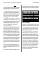
IntelliPack Series 851T Transmitter/Alarm User's Manual
Strain Gauge Input
___________________________________________________________________________________________
If using a precision millivoltage source to drive the input, it is
suggested that you also adjust the internal excitation source to a
level that will approximate your final application (the A/D
reference is derived from the excitation).
If you wish to drive your bridge via your own excitation
source, the IntelliPack Configuration Software allows you to turn
OFF the internal excitation supply. In this mode, you must limit
your excitation voltage between 4V and 11V DC. Do not exceed
these limits or damage to the unit may result. Keep in mind that
the A/D reference is generated via the excitation supply and you
must complete this circuit by including the EXC and SEN lead
connections, just as if you were using internal excitation.
Likewise, since the unit no longer has closed loop control of the
excitation voltage under these conditions, make sure that your
supply provides a clean, steady voltage to the bridge, or
measurement accuracy may be compromised. AC bridge
excitation is not permissible for use with this module.
Prior to field calibration, the module’s input type, bridge
configuration, excitation level, and sensitivity must already be set
via the IntelliPack Configuration Software. Input levels outside of
150% of full rated load (excitation level multiplied by sensitivity)
will not be acceptable for zero, full-scale, setpoint, or dropout
calibration. Since input levels cannot be validated during field
programming, entering incorrect signals can produce an
undesired output response. Install a jumper between the output
“I+” and “JMP” terminals for voltage output, remove this jumper
for current output.
WARNING: You must use the IntelliPack Configuration Software
to turn OFF the internal excitation supply BEFORE you connect
the unit to an external excitation source, or damage to the unit
may result. Do not exceed rated excitation voltage limits.
Equipment Required
A bridge calibrator, strain indicator calibrator, simulator, or
weights/dummy loads may be used as an input source.
Optionally, a precision millivolt source may also be used to drive
the input. In any case, the resultant signal source must be
accurate over the range required for zero and full-scale, and
alarm setpoint and dropout levels.
FIELD CONFIGURATION AND ADJUSTMENT
This program mode allows adjustment to key transmitter
calibration and alarm parameters in the field, without having to
connect a host computer. Field reprogrammability of zero & fullscale (input to output scaling), plus alarm setpoint & deadband
(Model 851T-1500), is alternately accomplished via this
transmitter/alarm module’s “SET”, “MODE”, “UP”, and “DOWN”
push buttons, and the zero/full-scale and relay LED’s (see
Drawing 4501-888) as described here.
Note: For best results, the input source must be accurate
beyond the required specifications. An accurate current or
voltage meter is also required to monitor the output level. Ideally,
this meter must be accurate beyond the module specifications.
Before attempting field calibration, consider that in the field,
the use of an application’s actual sensor, load cell, or bridge
arrangement can make field calibration impractical in some
cases, as it would require that precise calibration loads or
stresses be applied, including load equivalents for alarm levels,
as well as zero and full-scale. Further, the accurate simulation of
strain gauge bridges is often impractical due to wide variances in
their application and offsets. Complete calibration is most easily
accomplished via the IntelliPack Configuration Software.
The following procedure uses the corresponding zero/fullscale (labeled “Z/FS”) and relay (labeled “RLY”) LED’s to indicate
which parameter is being programmed. A constant ON zero/fullscale LED refers to zero configuration (scaling input for 0%
output), a flashing ON/OFF zero/full-scale LED refers to fullscale/span configuration (scaling input for 100% output). A
constant ON relay LED indicates setpoint adjustment, a flashing
ON/OFF relay LED indicates dropout/deadband adjustment.
Refer to Table 4.
Transmitter/Alarm General Field Programming Procedure
Field configuration of zero and full-scale via the front panel
push-buttons is essentially equivalent to the scaling operation
performed via the Transmitter Configuration page of the
IntelliPack software. That is, you define the input for 0% output,
and the input for 100% output. However, in field calibration, you
may map a minimum input signal to an output signal up to 20% of
nominal full-scale, and a maximum input signal to an output
signal from 60 to 110% of nominal full-scale. In other words, your
zero calibration may include offset (up to 20%) and you do not
have to use an equivalent full-scale load to accurately calibrate
your output response (you can use 60-110% of full-scale). You
may choose to include tare in your field zero calibration, but are
limited to 20% of full-scale. For greater tare weights, you can
always trigger tare offset generation in the field without limitation
via the digital input trigger (see Electrical Connections).
Table 4: Field Configuration LED Program Indication
LED INDICATOR
CONSTANT ON
FLASHING
Yellow
Zero/Full-Scale
Zero
Full-Scale
(labeled “Z/FS”)
851T-1500 Only
Yellow Relay
High or Low
High or Low
(labeled “RLY”),
Setpoint
Dropout
CAUTION: Do not insert sharp or oversized objects into the
switch openings as this may damage the unit. When depressing
the push-buttons, use a blunt tipped object and apply pressure
gradually until you feel or hear the tactile response.
IMPORTANT: This module performs a ratiometric conversion of
the input signal and the A/D reference is derived from the bridge
excitation voltage via the sense leads. Thus, the module requires
that the excitation and sense lead connections be intact in order
to complete a conversion. That is, simply connecting a millivolt
source to the input in order to simulate a bridge signal will not
work without also completing the excitation and sense wiring, and
installing the half-bridge completion jumper at TB2-1 & TB2-2 (to
properly bias the input source).
Note: The bridge excitation level, the gauge rated output, and the
input type/wiring can only be set via the IntelliPack Configuration
Program. Calibration is optimally performed via the Intellipack
Software, but field program mode provides an alternate form of
input-to-output calibration by allowing you to scale virtually any
portion of the input range to the selected output range via the
front panel push buttons, and tare generation via the digital input.
- 17 -