1
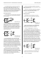
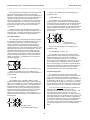
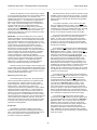
IntelliPack Series 851T Transmitter/Alarm User's Manual
Strain Gauge Input
___________________________________________________________________________________________
Rs = [Rg * 106 / (GF * N * Es)] – Rg – 2 * Rl
The following table lists the simulated microstrain
(compressive) for various resistance values when shunted across
the active strain gauge of a quarter-bridge circuit (N=1) for 120Ω
and 350Ω strain gauges. These values assume a gauge factor
setting of 2.0000.
To apply these equations, it is assumed that the resistance of
each leg of the bridge is equal and the bridge is balanced prior to
performing shunt calibration. Note that the strain simulated by
shunting Rg with Rs is always negative (compressive) and the
negative sign is commonly omitted.
Table 3: Shunt Resistor & Simulated Strain (Quarter Bridge)
120Ω Gauges
350Ω Gauges
Shunt
Microstrain
Shunt
Microstrain
1MΩ
59.8 µε
1MΩ
174 µε
599880Ω
100 µε
349650Ω
500 µε
200KΩ
299 µε
200KΩ
872 µε
119880Ω
500 µε
174650Ω
1000 µε
100KΩ
598 µε
100KΩ
1744 µε
59880Ω
1000 µε
87150Ω
2000 µε
50KΩ
1197 µε
50KΩ
3476 µε
29880Ω
2000 µε
57983Ω
3000 µε
20KΩ
2978 µε
43400Ω
4000 µε
19880Ω
3000 µε
34650Ω
5000 µε
14880Ω
4000 µε
20KΩ
8510 µε
11880Ω
5000 µε
17150Ω
10000 µε
5880Ω
10000 µε
In performing shunt calibration, the simulated strain Es is
calculated as shown and compared to the actual measured value
of the module. If the two values differ significantly, then the
measured response of the module can be rescaled by varying the
module’s Instrument Gauge Factor or Software Gain, until the
indicated output properly registers the calculated (simulated)
strain. That is, the effect of shunt calibration is to rescale the
module’s sensitivity, and this process is also referred to as
Instrument Scaling.
To accurately perform shunt calibration, you should apply the
shunt at the bridge, and not at the instrument. However, in some
cases it may not be convenient to apply the shunt at the gauge.
If the shunt resistor is local to the instrument, then you must
provide separate leads to the bridge resistor that is to be shunted
(these leads must be of equal length and gauge). For your
convenience, this module provides screw terminals for installation
of a shunt calibration resistor, plus connections to a switch in
order to enable or disable the shunt. Refer to Electrical
Connections Drawing 4501-886.
Excitation Level Adjustment
This module employs a ratiometric input conversion method
that derives the A/D reference voltage from the variable excitation
voltage level. As a result, an indicated strain will remain relatively
constant as the value of the excitation voltage is changed.
The IntelliPack Configuration Software provides an entry field
for your shunt resistance (Rs), as well as a field that is used to
identify the leg or bridge resistor that is shunted for a specific
bridge configuration (the calibration element). A graphic figure is
shown with reference designators for the standard quarter, half,
and full bridge configurations. Fields for Instrument Gauge
Factor and Software Gain Factor are also provided. A calculator
is also built in to calculate the required shunt resistance for a
specific simulated strain. With the shunt resistance applied to the
bridge element, you simply click the “Update” button which will
use the parameters you provided to calculate a simulated strain
(this calculation uses the actual strain Gauge Factor and a fixed
gain of 1.0), and simultaneously sample the input voltage and
indicate its measurement using the same parameters, except the
indicated value is computed with the Instrument Gauge Factor
substituted for the strain Gauge Factor and the result is multiplied
by the software Gain Factor. Typically, you would adjust the
Instrument Gauge Factor and/or Gain Factor as required, and
again click “Update”, until your indicated measurement closely
approximates the simulated value (internally calculated). Varying
the software Gain Factor or Instrument Gauge Factor effectively
adjusts the instrument’s sensitivity for its indication of relative
strain.
The output of a bridge is directly proportional to the bridge
excitation voltage. Normally, the highest adjustment of bridge
excitation voltage should be used while taking into account the
gauge manufacturer’s recommendations and the negative effect
of self-heating in the bridge resistors.
The internal bridge excitation supply of this model can be
adjusted from roughly 4V to 10V at the bridge, and is driven via
an adjustable regulator whose output is controlled via a 100 value
digital pot. The excitation level at the bridge is sensed via the
remote sense lines to the bridge (SEN+ and SEN-). Remote
sensing will allow the module to boost the output level so that the
programmed excitation level is maintained at the remote bridge,
effectively correcting for any lead resistance drop. These lines
also drive the divider used to generate the reference to the A/D.
A fixed reference voltage input to a second channel of the A/D
(the actual A/D reference varies with excitation level) allows the
excitation level to be read back in closed loop fashion. This
permits the unit to make adjustments to the excitation level in
order to compensate for load, lead-wire, and temperature effects.
You simply enter the excitation level you desire, and the unit
adjusts to that level. The excitation supply also has sufficient
overdrive capability to allow up to 1V of total EXC lead resistance
drop. Note that in some cases, resolution limitations will only
allow the module to approximate your nominal excitation level,
typically to within 93mV. Higher than expected lead-wire
resistance may also limit the excitation level obtained at the
bridge. In any case, the software displays the actual excitation
level obtained at the bridge via the remote sense leads and this
may differ from your desired excitation.
The IntelliPack Configuration Software includes a built-in
Shunt Resistor Calculator that will calculate a required shunt
resistance for a specific simulated microstrain. Keep in mind that
the accuracy of the resistance and simulated strain calculations
diminishes above simulated strains greater than about 2000
microstrain.
IMPORTANT: Shunt Calibration should only be performed on
unstrained gauges. Bridge offsets should be nulled prior to shunt
calibration. Always allow the module to warm up several minutes
prior to performing shunt calibration.
- 16 -