1
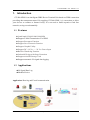
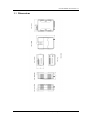
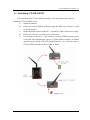
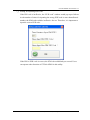
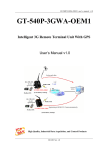
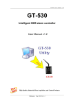
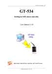
GT-540-OEM1 user manual v1.1 GT-540-OEM1 Intelligent GPRS Data Server User Manual v1.1 High Quality, Industrial Data Acquisition, and Control Products Publication Feb, 2010 Ver. 1.1 GT-540-OEM1 user manual v1.1 Warranty All products manufactured by ICP DAS are warranted against defective materials for a period of one year from the date of delivery to the original purchaser. Warning ICP DAS assumes no liability for damages consequent to the use of this product. ICP DAS reserves the right to change this manual at any time without notice. The information furnished by ICP DAS is believed to be accurate and reliable. However, no responsibility is assumed by ICP DAS for its use, or for any infringements of patents or other rights of third parties resulting from its use. Copyright Copyright 2009 by ICP DAS CO., LTD. All rights reserved worldwide. Trademark The names used for identification only may be registered trademarks of their respective companies. Version Date Author Description 1.1 2010/02/23 Alung Release version Publication Feb, 2010 Ver. 1.1 GT-540-OEM1 user manual v1.1 Table of Contents 1. Introduction ............................................................................................... 1 1.1 1.2 Features............................................................................................................. 1 Applications...................................................................................................... 1 2. Hardware ................................................................................................... 2 2.1 2.2 2.3 2.4 2.5 2.6 2.7 Specifications ................................................................................................... 2 Appearance and pin assignments...................................................................... 4 Dimensions ....................................................................................................... 5 DI/DO Wire Connection................................................................................... 6 LED indicators.................................................................................................. 7 Installing GT-540-OEM1.................................................................................. 8 How to reset GT-540-OEM1 ............................................................................ 9 3. Installing GT-540-OEM1 Utility............................................................. 10 3.1 3.2 Installing .NET Compact Framework ............................................................ 10 Installing GT-540-OEM1 Utility .................................................................... 12 4. GT-540-OEM1 Utility operation............................................................. 15 4.1 4.2 4.3 4.4 4.5 4.6 4.7 4.8 4.9 Main menu...................................................................................................... 16 Login............................................................................................................... 18 Device Parameters .......................................................................................... 20 Device Time.................................................................................................... 27 Counter Value ................................................................................................. 29 DO control/DI status....................................................................................... 30 Signal Quality ................................................................................................. 31 Version ............................................................................................................ 32 System ............................................................................................................ 33 5. Firmware Update..................................................................................... 35 5.1 5.2 Hardware and software................................................................................... 35 Update Process ............................................................................................... 35 6. Data log and upload................................................................................. 37 6.1 6.2 Data format ..................................................................................................... 37 Process of Upload E-Mail .............................................................................. 38 7. Troubleshooting....................................................................................... 39 Publication Feb, 2010 Ver. 1.1 -I- GT-540-OEM1 user manual v1.1 1. Introduction GT-540-OEM1 is an intelligent GPRS Device Terminal Unit based on GPRS connection providing data transparent tunnel. By applying GT-540-OEM1, it is convenient to allow your devices to connect to Internet easily. It is not need to build expensive fixed line network, saving cost substantially. 1.1 Features z Quad-band 850/900/1800/1900 MHz z Support E-Mail Transmission Via GPRS z Support Reconnect Function z Support Save Electronic Function z Support Graphic Utility z Support DC +10 VDC ~ +30 VDC Power Input z Built-in Watch-dog Function z Industrial Design with Surge Protection z Support microSD Storage Card z Support automatic I/O signal data logging 1.2 Applications z IO Signal Date Log z Modbus Device Application: Data log and E-mail communication GT-540-OEM1 User Manual, Version 1.1, February 2010 1/39 GT-540-OEM1 user manual v1.1 2. Hardware 2.1 Specifications System CPU 32 bit Arm7 CPU, 72 MHz SRAM 32 KB Flash Memory 512 KB RTC Gives time(sec, min, hour) & date, leap year compensation from 1980 to 2079 WDT(watchdog) Yes Serial ports RS-232:TxD,RxD,GND for configuration COM2 RS-485:Transparency for communication with ICP DAS COM3 Modbus RTU devices DIO Input 6 Channel On Voltage: +3.5~24VDC Off Voltage: +1V Max. Output D/O :2 Channel (isolation) Load Voltage: +24V Max. Load Current: 100 mA Max. GPRS/GSM Module GPRS/GSM Power Protection Frame Ground Protection GPRS/GSM Tri-Band 900/1800/1900 MHz GPRS multi-slot : class 10/8 GPRS mobile station : class B GPRS class 10 : Max download speed 85.6 kbps CSD max speed 14.4 kbps Compliant to GSM phase 2/2+ -Class 4(2W @ 900 MHz) -Class 1(1W @ 1800/1900 MHz) Coding schemes : CS 1, CS 2,CS 3,CS 4 Reverse polarity protection ESD, Surge, EFT, Hi-Pot GT-540-OEM1 User Manual, Version 1.1, February 2010 2/39 GT-540-OEM1 user manual v1.1 Required Supply Voltage Mechanical Casing +10 VDC ~ +30 VDC Plastic Flammability Dimensions (W x H x D) Installation Environment Operating Temperature Storage Temperature Humidity UL 94V-0 materials 91 mm x 132 mm x 52 mm DIN-Rail -25 °C ~ +55 °C -40 °C ~ +80 °C 5 ~ 95% RH, non-condensing GT-540-OEM1 User Manual, Version 1.1, February 2010 3/39 GT-540-OEM1 user manual v1.1 2.2 Appearance and pin assignments Pin assignments: DI/DO Terminal No. DI DI COM DO PWR DO DO GND Ain+ Ain- 01 02 03 04 05 06 07 08 Pin Assignment DI0 DI1 DI2 DI3 DI4 DI5 DI COM DO PWR 09 10 DO0 DO1 11 DO GND 12 13 14 Ain+ Ain- COM Port & Power Input Terminal No. Ground for COM COM2 RS-232 COM3 RS-485 Reset Power Input: +10 ~ 30VDC Frame Ground Pin Assignment 01 02 03 04 05 06 07 GND RxD2 TxD2 D+ DRST+ RST- 08 09 10 DC.+VS DC.GND F.G GT-540-OEM1 User Manual, Version 1.1, February 2010 4/39 GT-540-OEM1 user manual v1.1 2.3 Dimensions GT-540-OEM1 User Manual, Version 1.1, February 2010 5/39 GT-540-OEM1 user manual v1.1 2.4 DI/DO Wire Connection (1) DI Wire Connection (2) DO Wire Connection GT-540-OEM1 User Manual, Version 1.1, February 2010 6/39 GT-540-OEM1 user manual v1.1 2.5 LED indicators There are three LED indicators to help users to judge the various conditions of GT-540-OEM1. The description is as follows: A. EXT(Red):External Power LED to indicate whether the external power is input or not. The description is as follows: B. The external power is active The external power is not active on off STA(Orange):System LED is to indicate if the GT-540-OEM1 is normal or fail. Normal Device Fail PIN code is wrong Blanking (1 sec) Always on or off Blinking per 50 ms C. GSM (Green):The modem LED can indicate the status of GSM module. Modem normal Blanking (3 sec) Modem fail Off or Blanking (not 3 sec) GT-540-OEM1 User Manual, Version 1.1, February 2010 7/39 GT-540-OEM1 user manual v1.1 2.6 Installing GT-540-OEM1 If users want to start GT-540-OEM1 normally, it needs to follow these steps to install the GT-540-OEM1 below: A. Install the antenna B. Plug in the normal SIM card (Before apply the SIM card, confirm it is OK by mobile phone.) C. Pin08 and Pin09 connect to the DC.+VS and DC.GND of the power supply. D. Follow the section 2.4 to wire the I/O connection. E. It is needed to wait for 30 ~ 50 seconds to search the GSM base and register to the ISP. After finishing the process, GT-540-OEM1 would be in normal operation mode and the STA LED would blank per 3 sec. The start time of GT-540-OEM1 depends on the strength of signal. GT-540-OEM1 User Manual, Version 1.1, February 2010 8/39 GT-540-OEM1 user manual v1.1 2.7 How to reset GT-540-OEM1 (1) (2) Turn off the external power and confirm the EXT LED is off. Turn on the power. GT-540-OEM1 User Manual, Version 1.1, February 2010 9/39 GT-540-OEM1 user manual v1.1 3. Installing GT-540-OEM1 Utility It needs the runtime environment with .NET Framework 2.0 or above to execute the GT-540-OEM1 Utility in the PC. If there has .NET Framework 2.0 or above in the PC, the section 3.1 can be omitted. 3.1 Installing .NET Compact Framework A. Download .NET Compact Framework 2.0 at the following URL: http://m2m.icpdas.com/download.html B. Execute setup file “dotnetfx20.exe” C. The install figure is as follows: (1) Press “Next” to the next step. (2) Select the “I accept the terms of the License Agreement” and “Install ” to the next step. GT-540-OEM1 User Manual, Version 1.1, February 2010 10/39 GT-540-OEM1 user manual v1.1 (3) The installation process would be going (4) After finishing the installation, press “Finish” to exit the program. GT-540-OEM1 User Manual, Version 1.1, February 2010 11/39 GT-540-OEM1 user manual v1.1 3.2 Installing GT-540-OEM1 Utility A. Execute “Install_GT540_OEM1_Utility.exe” B. The installation figure is as follows: (1) Press “Next” to start the installation procedure. (2) Select the installation path. The default path is Files\GT-540-OEM1 Utility”. Press “Next” to the next step. GT-540-OEM1 User Manual, Version 1.1, February 2010 ”C:\Progrm 12/39 GT-540-OEM1 user manual v1.1 (3) Input the name shown in “All Programs”. Press “Next” to the next step. (4) After finishing the installation procedure, press “OK” to the next step. GT-540-OEM1 User Manual, Version 1.1, February 2010 13/39 GT-540-OEM1 user manual v1.1 (5) Press ”Finish” to finish the installation procedure. (6) Launch GT-540-OEM1 Utility from the start menu ”StartÆAll ProgramsÆGT-540-OEM1 UtilityÆGT-540-OEM1 Utility”. GT-540-OEM1 User Manual, Version 1.1, February 2010 14/39 GT-540-OEM1 user manual v1.1 4. GT-540-OEM1 Utility operation Before GT-540-OEM1 utility is connected to the PC correctly, please confirm these following steps: 1. The STA LED is blanking. There are 2 kinds of blanking in GT-540-OEM1. STA LED 2. 3. Description Blanking per 1 sec Normal mode Blanking per 50 ms The pin code is wrong. The login windows would show the field to input pin or PUK code Confirm the RS232 connection between GT-540-OEM1 and PC is correct. Users can refer to the following figure. During the setting procedure, the external power must be turn on. GT-540-OEM1 User Manual, Version 1.1, February 2010 15/39 GT-540-OEM1 user manual v1.1 4.1 Main menu The main menu of GT-540-OEM1 Utility includes the following sections: A. Tool menu (1) “COM”: Set the COM port number in PC connecting to GT-540-OEM1. (2) Login/Logout: Before operating GT-540-OEM1, users need to login to GT-540-OEM1 Utility. After login the system successfully, the menu item “login” would become “logout” and the GT-540-OEM1 Utility would be operated normally. Once the power is reset, the login procedure needs to do again. (3) “Language” GT-540-OEM1 Utility just supports English now, but it will support multi-language in the future. (4) File There are import and export functions in “File” item. The functions would be enabled when “Main parameters” window is open. Export: The function can export the parameters as .par file from the “Main parameters” windows. Import: The parameters would be shown in “Main parameters” window from the specific .par file. (5) Version: Including the firmware and Utility version information. GT-540-OEM1 User Manual, Version 1.1, February 2010 16/39 GT-540-OEM1 user manual v1.1 (6) (7) System: Provide users for recovering GT-540-OEM1 to factory ,resetting GT-540-OEM1 and debug mode. Exit: To exit GT-540-OEM1 utility B. 5 function item : (1) “Main parameter”: The main parameter setting of GT-540-OEM1 includes E-mail address, mail server, Modbus device, data log, scan time and comport setting. (2) “Device time”: Display and set the RTC time of GT-540-OEM1. It is also can get the information of the last and next time of the return report. (3) “DO Control/DI statuses”: Display the status of I/O and control the DO output. (4) “Signal Quality”: Show GSM signal strength in GT-540-OEM1 (5) Counter Value: Enable or disable counter function and show or set counter value. C. (1) (2) (3) (4) Status Line Show the related information during the operation procedure including: The com port number of PC The communication setting of COM Port The status of COM Port The result of Utility operation GT-540-OEM1 User Manual, Version 1.1, February 2010 17/39 GT-540-OEM1 user manual v1.1 4.2 Login It needs to login into GT-540-OEM1 to set its parameters. The description is below: (1) Select the COM port number of PC. (2) Press the “login” button (3) If you are the first time to login, please set the time of GT-540-OEM1. If the pin code in GT-540-OEM1 is not correct, the STA led would be blanking per 50 ms and GT-540-OEM1 utility would ask for users to input Pin or PUK code. (1) Asking for inputting PIN code: If the PIN code is effective, the “Enter SIM PIN/SIM PUK” window would pop-up as follows. If the number of times for inputting the wrong PIN code is more than the allowed number, the PIN code would be ineffective. And the “PUK code” window would pop up. GT-540-OEM1 User Manual, Version 1.1, February 2010 18/39 GT-540-OEM1 user manual v1.1 (2) Asking for inputting PUK code If the PIN code is ineffective, the “PUK code” window would pop-up as follows. As the number of times for inputting the wrong PUK code is more than allowed number, the SIM card would be ineffective forever. Therefore, it is important to input the correct PUK code. If the PIN or PUK code is correct, the STA led would blank per second. Users can operate other function of GT-540-OEM1 in this utility. GT-540-OEM1 User Manual, Version 1.1, February 2010 19/39 GT-540-OEM1 user manual v1.1 4.3 Device Parameters There are 2 pages in “Device parameter” window. They are “Scan Time/E-mail” and “Modbus Device” pages. After configuring the 2 pages, press “Write to Device” button to save these settings to GT-540-OEM1. Then, reset GT-540-OEM1 to enable these settings. The “Read Form Device” button can help users to read back these settings from GT-540-OEM1. In addition, these setting would be read from GT-540-OEM1 when the “Main Parameter” window pops up from the main menu. 4.3.1 Scan Time/E-mail The following page is “Scan Time/E-mail”. Users can refer the explanation below: 1. Device Information Textbox name describe Machine ID The device ID would be shown in the report. It can be used for recognizing the GT-540-OEM1. The length of characters is 20 without supporting Unicode and “;” characteristic. SIM Card Number This text field can show or input the phone number of the plug-in SIM card. Take Taiwan for example: 0928xxxxxx. 2. GPRS Information Textbox name describe GT-540-OEM1 User Manual, Version 1.1, February 2010 20/39 GT-540-OEM1 user manual v1.1 Access Point Name Access point name (APN) is the name used to identify a general packet radio service (GPRS) bearer service in the GSM mobile network. The APN defines the type of service that is provided in the packet data connection. You can get this APN by ISP. User name After the ISP registration, ISP will give you user name, and you can use GPRS by the user name. After the ISP registration, ISP will give you password, and you can use GPRS by the password. Password 3. The AI signal scale: Textbox name Describe Maximum If “Enable Scale” is checked ,the AI signal using three new fields that will be introduced by the user .These values must be used in the following formula:(max-min)/16*(AI-4) + min + offset Minimum and the result must be added in the attached file used in the e-mail. Offset 4. IO Scan Time/Report Time Textbox name describe IO Status Record Interval The GT-540-OEM1 can log IO status including Modbus RTU I/O in the micro SD. The value can set record time interval(unit: sec) Report Interval Set report time interval. The GT-540-OEM1 calculate time interval according to report base time.(unit: min) Report Base Time The GT-540-OEM1 calculate time interval according to report base time. (Unit: min), for example, if report base time set 8:30and report interval set 60 min, it will report data log at 9:30 from e-mail. 5. File Size Textbox name describe Max size of one attached file Max size of each attached file for e-mail and data log. If data is more than max size of one attached file, it will create new file to record data. Max size of one E-mail file Max size of one E-mail file, this value must more than max size of one attached file, Some mail server GT-540-OEM1 User Manual, Version 1.1, February 2010 21/39 GT-540-OEM1 user manual v1.1 limit one of the e-mail size. 6. Mail Server Textbox name Describe Authority NONE or AUTHORITY Mail Server Domain name Send mail server Domain name, if Domain and IP is setting, IP setting is primary. Mail Server IP IP of mail server Port TCP port of mail server for send e-mail Mail From(E-mail address) If the e-mail can’t send to user, it will return error message and e-mail to this e- User name User can register user name from mail server Password User can get password to match username from mail server Primary DNS The Domain Name System (DNS) is a hierarchical naming system for computers, services, or any resource connected to the Internet or a private network. You must give this value which is DNS server IP if you want to connect mail server by domain name. Secondary DNS Backup DNS server 7. E-mail subject Textbox name Describe E-mail Subject The User can change the e-mail subject from the field. GT-540-OEM1 User Manual, Version 1.1, February 2010 22/39 GT-540-OEM1 user manual v1.1 8. E-mail Address edit Name describe Add User can add e-mail address of the receiver by this bottom. The maximum of the E-mail address is 10. Update User can renew e-mail address of the receiver by this bottom 1. Select the receiver in the table 2. Renew E-mail on “E-mail address of the receiver” textbox 3. Chick update bottom. Delete User can delete e-mail address of the receiver by this bottom 1. Select the receiver in the table. 2. Chick delete bottom. E-mail address of the receiver table You can add, delete or update form this textbox. Receiver list. GT-540-OEM1 User Manual, Version 1.1, February 2010 23/39 GT-540-OEM1 user manual v1.1 4.3.2 Modbus Device Another page in “Device parameter” is about Modbus device setting. The explanation is below: The GT-540-OEM1 supports Modbus RTU. If users add, update, or delete device by utility. Function Describe Baud rate Baud rate of device, The GT-540-OEM1 supports baud rate detection: 1200, 2400, 4800, 9600, 19200, 38400, 57600 and 115200. Device name You can select Modbus RTU device (Only ICP DAS products). The maximum of the Modbus devices is 3. Device addr 1-247,Modbus address according to Modbus device Channels Channel number Start address Start address of IO in the Modbus device. The details please refer Modbus device manual Data format 2's comp HEX/Engineering unit Type code Add Please refer Modbus device configuration User can add Modbus device by this bottom. The maximum of the Modbus devices is 3.hy6 Update User can renew configuration of the Modbus device by this bottom 1. Select the Modbus device in the table 2. Renew configuration 3. Chick update bottom. Delete User can delete configuration of the Modbus device by this bottom 1. Select the receiver in the table. 2. Chick delete bottom. GT-540-OEM1 User Manual, Version 1.1, February 2010 24/39 GT-540-OEM1 user manual v1.1 4.3.3 Add new Modbus Device If device name doesn’t exist in the Device Name list, Users can add new device on the following step and figures. 1. Select Custom in the Device Name list box 2. Rename “Custom” 3. Set Device Address, DI/DO/AI/AO channels, start address, and date format. The GT-540 just supports HEX value for AI/AO. The 16-bit data format can support to the maximum number of channel is 32. The 32-bit data format can support to the maximum number of channel is 16. The 64-bit data format can support to the maximum number of channel is 8. GT-540-OEM1 User Manual, Version 1.1, February 2010 25/39 GT-540-OEM1 user manual v1.1 4. Click “Add” button 4.3.4 Import/Export Parameters Users can use the import and export functions from the menu bar. This function would be enabled when the “Device Parameter” window is open. The explanation is below: A. Import Parameters:This function is used for reading back the setting of device parameters from .par file and displaying in “Device parameter” window. When press “import” button, a file selection window would pop up for users to choice GT-540-OEM1 User Manual, Version 1.1, February 2010 26/39 GT-540-OEM1 user manual v1.1 the .par file. B. Export Parameters: The function is used for saving the setting of “Device parameter” window as .par file. When press “Export” button, a file selection window would pop-up for users to save the setting as .par file in specific path. 4.4 Device Time This window provides the function to inquire and modify the time of GT-540-OEM1. Besides, the next and last report times are also shown. The text field operation is below. GT-540-OEM1 User Manual, Version 1.1, February 2010 27/39 GT-540-OEM1 user manual v1.1 Text field: (1) Device time: show the time of GT-540-OEM1. Users also can change the time in this field to key in the specific time. (2) Next Report Time : show the next report time (3) Last report time : show the last report time Operation: (1) “Set as Now”: Set the PC time to GT-540-OEM1. After setting the time successfully, the information of GT-540-OEM1 time and report time would be updated. (2) Set: Set the GT-540-OEM1 time according the “Device Time” field. After setting the time successfully, the information of GT-540-OEM1 time and report time would be updated. (3) Read: Read back the time of GT-540-OEM1, the next report time and the last report time. GT-540-OEM1 User Manual, Version 1.1, February 2010 28/39 GT-540-OEM1 user manual v1.1 4.5 Counter Value The window provides the function to enable or disable function and inquire or modify the counter values of DI0 ~ DI5. The explanation of operation and text field is below: Text field: 1. Name: The DI name of DI0 ~ DI5。 2. Enable Counter: DI Counter enables or disable. 3. Value : The current counter value ( maximum: 999999999) 4. Set Value: Input the defined counter value. The maximum is 999999999. This field is enabled when DI is set as counter mode. Operation: 1. Read: Read the current counter value from GT-540. If the “Enable Counter” is not checked, the counter value is 0. 2. Set: Change the counter value into GT-540 according to the "Set Value" Datalog file format: 1. If the DI counter function is enabled, the title will show “CIx”(x: channel number) in .csv file, and the content is counter value. 2. If the DI counter function is disabled, the title will show “DIx”(x: channel number) in .csv file, and the content is signal value(0 or 1). The sample: GT-540-OEM1 User Manual, Version 1.1, February 2010 29/39 GT-540-OEM1 user manual v1.1 4.6 DO control/DI status The function is used for controlling DO and reading the status of DIs: Text field (1) DI0 ~ DI6、DO0 ~ DO1: Grey:The voltage logic is high. Red:the voltage logic is low Operation (1) Read : Read back the status of DI0 ~ DI6 and DO0 ~ DO1 from GT-540-OEM1. (2) DO0 ~ DO1 ON:Set the DO output on (3) DO0 ~ DO1 OFF:Set the DO output off GT-540-OEM1 User Manual, Version 1.1, February 2010 30/39 GT-540-OEM1 user manual v1.1 4.7 Signal Quality This window can show GSM signal strength. Text field: The strength is divided into 5 sections shown in percentage. Operation: (1) Read:Read the GSM signal strength. GT-540-OEM1 User Manual, Version 1.1, February 2010 31/39 GT-540-OEM1 user manual v1.1 4.8 Version Press "Version" in tool menu, and the window would show the version of Utility and firmware. Text field: (1) Firmware version: show the version information of GT-540-OEM1’s firmware (2) Utility version: show the version information of GT-540-OEM1’s utility Operation: Read: Read this information from GT-540-OEM1. GT-540-OEM1 User Manual, Version 1.1, February 2010 32/39 GT-540-OEM1 user manual v1.1 4.9 System “System” menu item has 3 functions of recovering factory setting and resetting GT-540-OEM1 4.9.1 Recover to Factory Settings The function is used to recover GT-540-OEM1 as factory settings including password. The steps are below: (1) Make sure the STA led is blanking per 1 sec. (2) Select the Recover to Factory Settings. 4.9.2 Reset GT-540-OEM1 The function is used to reset GT-540-OEM1 by software. (1) Make sure STA led is blanking per 1 second (2) Select “Rest GT-540-OEM1” button to reset GT-540-OEM1. GT-540-OEM1 User Manual, Version 1.1, February 2010 33/39 GT-540-OEM1 user manual v1.1 4.9.3 Debug Window The function is used to test E-mail and save setting log. The steps are below: Debug mode has 4 Items of Mail test, Monitor, save message, and clear. 1. Mail test: Users can send e-mail form utility by the GT-540, and users can see the log of process. 2. Monitor: Users can see all command and response, and users can save the log of process. 3. Save message: save command and response log(*.txt) 4. Clear: clear message GT-540-OEM1 User Manual, Version 1.1, February 2010 34/39 GT-540-OEM1 user manual v1.1 5. Firmware Update 5.1 Hardware and software 5.1.1 Hardware GT-540-OEM1 module Download Cable Power Cable 10V ~ 30V 5.1.2 Software 1. Download tool : ISP_Firmware_en.exe 2. Firmware file(*.fw) 5.2 Update Process 1. GT-540-OEM1 power input pin connect to DC power supply 2. Connect download cable with GT-540-OEM1 J2 and PC COM port GT-540-OEM1 User Manual, Version 1.1, February 2010 35/39 GT-540-OEM1 user manual v1.1 3. 4. 5. 6. 7. 8. Turn on the DC power Rrun ISP_Firmware_en.exe in PC Select serial port Click “Browser”, and select file to update (*.fw) Click “Firmware Update” , and wait to update after success ,click “Exit” to exit 1. Select serial port 2. Select file 3. Update information 4. Start update GT-540-OEM1 User Manual, Version 1.1, February 2010 36/39 GT-540-OEM1 user manual v1.1 6. Data log and upload The GPRS maybe happen disconnect during transmission, and the GT-540-OEM1 support data log and data upload for complete data. This chapter will introduce process and format for data log. P.S It doesn’t support SSL/TLS encryption. 6.1 Data format The file format is "*.csv" that divided each record with ",".In each file, the title is name of record, and according to the order are date, The GT-540-OEM1 IO data, and Modbus device data. Example: 2009/09/24 17:55:18 Local DI0~DI1: Counter mode (title CI) Local DI2~DI5: DI mode (title DI) Modbus device M-7016 Address: 5 DI*1, DO*4, AI*2, AO*1 Record data: Date CI0 CI1 DI2 DI3 DI4 DI5 DO0 DO1 AI0 Module [M-7016] Addr. DI0 DO0 DO1 DO2 20090924 175518 119 230 0 0 0 0 0 0 -0.492 5 1 1 1 1 20090924 175519 119 230 0 0 0 0 0 0 -0.493 5 1 1 1 1 DO3 AI0 AI1 AO0 1 0.001 0.002 6.8 1 0.001 0.003 6.8 GT-540-OEM1 User Manual, Version 1.1, February 2010 37/39 GT-540-OEM1 user manual v1.1 6.2 Process of Upload E-Mail Please refer flow chart below. The system would create record file by date of now and scan time that user can differentiate variety of data. The GT-540 records data continuously when it uploads data. Example: Date: 2009/09/28 06:30 PM , scan time : 1 The file name is "20090910_1830_1.csv". The new file will be created when the event is on condition below. 1. Users add, update, delete Modbus device 2. The size of file is over the setting 3. Upload report time 4. Update scan time GT-540-OEM1 User Manual, Version 1.1, February 2010 38/39 GT-540-OEM1 user manual v1.1 7. Troubleshooting Item Trouble state Solution EXT LED is off Please check the external power and wire connection. 2 STA is always on Check SIM card Check Antenna Check the GSM signal strength 3 Check STA LED blinking every 1 sec GT-540-OEM1 Utility can’t connect Check com port connection and baud rate to GT-540-OEM1 setting 4 STA led is blanking per 50 ms 1 The pin code is wrong. The login windows would show the field to input PIN or PUK code GT-540-OEM1 User Manual, Version 1.1, February 2010 39/39