1
Babel Buster BB2-7010
1 of 2
file:///C:/AAA_CSI/Literature/2015 User Guides/BB2-7010 User Guide...
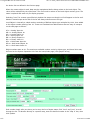
BB2-7010 User Guide Contents
Babel Buster 2
Model BB2-7010
BACnet Modbus Gateway
Rev. 1.3 – Oct. 2015
© 2015 Control Solutions, Inc.
1
1.1
1.2
1.3
1.4
Introduction
How to Use This Guide
Overview of Gateway Devices
Important Safety Notice
Warranty
2
Connecting BB2-7010 for the First Time
3
Minimum BB2-7010 Gateway Setup
4
Using the BB2-7010 as a BACnet Server
5
5.1
5.2
5.3
5.4
5.5
Configuring BB2-7010 as a Modbus RTU Master
Modbus RTU Device Configuration
Modbus RTU Master Read Maps
Modbus RTU Master Write Maps
Modbus RTU Master Data Displayed Per Slave
Modbus RTU Errors
6.
6.1
6.2
6.3
6.4
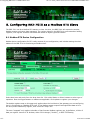
Configuring BB2-7010 as a Modbus TCP Client
Modbus TCP Device Configuration
Modbus TCP Client Read Maps
Modbus TCP Client Write Maps
Modbus TCP Errors
7
7.1
7.2
7.3
7.4
Using the BB2-7010 as a BACnet Client
BACnet Device Configuration
BACnet Client Read Maps
BACnet Client Write Maps
BACnet Errors
8
8.1
8.2
Modbus RTU Slave Configuration
Modbus RTU Device Configuration
Modbus RTU Slave Register Mapping
9
9.1
9.2
9.3
Modbus TCP Server Configuration
Modbus TCP Device Configuration
Modbus TCP Register Mapping
Modbus Virtual Device Register Mapping
10
SNMP Server Configuration
10.1
Local SNMP MIB
10.2
Trap Thresholds
10.3
SNMP Trap Destinations
11
SNMP Client Configuration
11.1
SNMP Device Configuration
11.2
SNMP Client Read Maps
11.3
SNMP Client Write Maps
11.4
SNMP Errors
12
HTTP Client
13
BBMD Setup
14
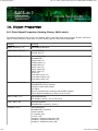
Object Properties
14.1
Data Object Properties (Analog, Binary, Multi-state)
14.2
Device Object Properties
15
Trouble Shooting
16
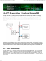
WiFi Sensor Setup - PointSix, AirTest
16.1
Sensor Network Settings
12/9/2015 11:25 AM
Babel Buster BB2-7010
2 of 2
16.2
16.3
file:///C:/AAA_CSI/Literature/2015 User Guides/BB2-7010 User Guide...
Configuration
Sensor Data Page
17
WiFi Sensor Setup - Veris Industries
17.1
Sensor Network Settings
17.2
Configuration
17.3
Sensor Data Page
18
WiFi Sensor Setup - Functional Devices RIB
18.1
Sensor Network Settings
18.2
Configuration
18.3
Sensor Data Page
18.4
Sensor Diagnostic Page
Appendix A
Hardware Details
A.1
Wiring
A.2
Front Panel LED Indicators
A.3
RS-485 Line Termination and Bias
12/9/2015 11:25 AM
1. Overview
1 of 2
1.1
file:///C:/AAA_CSI/Literature/2015 User Guides/BB2-7010/BB2-7010 ...
How to Use This Guide
The first few sections of this user guide provide background information on how the gateway works, and
an overview of the configuration process. The next several sections are guides for each of the tabs found
in the web interface in the gateway which is accessed by opening a web browser and browsing to the IP
address of the device.
You should at least read the overview sections to gain an understanding of how the gateway functions.
You can use the remaining sections as reference material to look up as needed. There is a "Quick Help"
section at the bottom of each web page in the gateway which is generally sufficient for quick reference in
setting up the gateway.
1.2
Overview of Gateway Devices
The Babel Buster BB2-7010 is a BACnet to Modbus gateway. It may be used as BACnet IP client and
server, Modbus TCP client and server, and Modbus RTU master or slave. The BB2-7010-02 may also be
used as SNMP client and server. The BB2-7010-06, -07, and -08 models add gateway capability for
specific types of WiFi sensors (see section 16, 17, 18).
The most common application for the BB2-7010 is interfacing a Modbus RTU device to a BACnet
IP network. The BB2-7010 will automatically poll the Modbus RTU device, and store the content if its
10/16/2015 12:30 PM
1. Overview
2 of 2
file:///C:/AAA_CSI/Literature/2015 User Guides/BB2-7010/BB2-7010 ...
registers in BACnet objects you assign. The BACnet system may then use standard BACnet services such
as Read Property to access the content of the Modbus registers. The BB2-7010 will also accept COV
subscriptions such that other devices will receive a COV notification when the content of a Modbus register
changes.
The BB2-7010 can be also configured as a Modbus RTU slave. This is useful when a PLC wants to write
data to the BB2-7010, thereby making the PLC's data available as BACnet object properties.
The BB2-7010 can be configured as a BACnet IP client. This means the BB2-7010 will be reading and
writing properties in other BACnet devices, storing copies of their object's Present Value in the BB2-7010.
The stored values may later be accessed by Modbus or SNMP.
1.3
Important Safety Notice
Proper system design is required for reliable and safe operation of distributed control systems
incorporating any Control Solutions product. It is extremely important for the user and system
designer to consider the effects of loss of power, loss of communications, and failure of
components in the design of any monitoring or control application. This is especially important
where the potential for property damage, personal injury, or loss of life may exist. By using
ANY Control Solutions, Inc., product, the user has agreed to assume all risk and responsibility
for proper system design as well as any consequence for improper system design.
1.4
Warranty
This software and documentation is provided “as is,” without warranty of any kind, either expressed
or implied, including, but not limited to, the implied warranties of fitness or merchantability for a particular
purpose. Control Solutions may make improvements and/or changes in this documentation or in the
product(s) and/or the program(s) described in this documentation at any time. This product could include
software bugs, technical inaccuracies, typographical errors, and the like. Changes are periodically made to
the information herein; these changes may be incorporated in new editions of the software.
10/16/2015 12:30 PM
2. Connecting the BB2-7010 for the First Time
1 of 4
file:///C:/AAA_CSI/Literature/2015 User Guides/BB2-7010/BB2-7010 ...
Follow these steps to make the initial connection to the BB2-7010.
(a) Connect power. Apply +12 to +24VDC or 24VAC to the terminal marked “POWER”, and common or
ground the the terminal marked “GND”.
(b) Connect a CAT5 cable between the RJ-45 jack on the top and your network switch or hub. You cannot
connect directly to your PC unless you use a “crossover” cable.
(c) Apply power. A blue LED inside the case should light indicating power is present. If the yellow LED on
the RJ45 jack is not on, check your Ethernet cable connections. Both green and yellow LEDs on the RJ45
jack will be on solid for a time during boot-up. The entire bootup process will take 1-2 minutes, during
which time you will not be able to connect with a browser.
(d) The default IP address as shipped is 10.0.0.101. If your PC is not already on the 10.0.0.0 domain, you
will need to add a route on your PC. Do this by opening a command prompt. First type “ipconfig” and note
the IP address listed. This is your PC’s IP address. Now type the command
route add 10.0.0.0 mask 255.255.255.0 1.2.3.4
but substitute your PC’s IP address for 1.2.3.4.
This generally works, but if this fails, you will need to temporarily change your computer’s IP address to a
fixed address that starts with 10.0.0. and ends with anything but 101.
10/16/2015 12:30 PM
2. Connecting the BB2-7010 for the First Time
2 of 4
file:///C:/AAA_CSI/Literature/2015 User Guides/BB2-7010/BB2-7010 ...
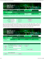
(e) Open your browser, and enter “http://10.0.0.101/” in the address window. You should see a page with
the “Babel Buster BB2-7010” header shown above. From this point, you will find help on each page in the
web site contained within the product.
(f) When you click on any of the page tabs such as System Setup, you will be asked for a user name and
password. The default login is user name “system” with password “admin”. You can also log in as “root”
using password “buster”. You should log in as “root” if you will be changing the IP address.
10/16/2015 12:30 PM
2. Connecting the BB2-7010 for the First Time
3 of 4
file:///C:/AAA_CSI/Literature/2015 User Guides/BB2-7010/BB2-7010 ...
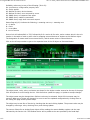
(g) To can change the IP address of the BB2-7010, go to the Local Host page under System :: Setup. The
following page should appear. Change the IP address, and subnet mask and gateway if applicable. Click
Change IP to save the changes. The process of programming this into Flash takes around half a minute.
The new IP address only takes effect following the next system restart or power cycle.
10/16/2015 12:30 PM
2. Connecting the BB2-7010 for the First Time
4 of 4
file:///C:/AAA_CSI/Literature/2015 User Guides/BB2-7010/BB2-7010 ...
(h) Most changes are stored in an XML configuration file in the device’s Flash file system. Only a few are
stored differently, and the IP address is one of those. Normally, clicking Update on any configuration page
only stores that configuration information to a temporary RAM copy of the configuration file. To make your
changes other than IP address permanent, you must click Save on the Config File page (System :: Setup
:: Config File).
10/16/2015 12:30 PM
3. Minimum BB2-7010 Gateway Setup
1 of 2
file:///C:/AAA_CSI/Literature/2015 User Guides/BB2-7010/BB2-7010 ...
The BB2-7010 requires only minimal configuration to be useful in its simplest form. First, you must assign
a device instance to the BB2-7010, and you do this via the BACnet IP Port page. You may leave all other
settings at their default. You could leave the device instance at its default as well. The only real
requirement is that you do not duplicate device instances.
The number of each type of available object is indicated here. Initially, there will be only 10 AI's and 1
each of the other object types. There is a pool of objects that may be shared among the different object
types. The number of objects available is displayed at the "System Capacities" link on the home page of
10/16/2015 12:31 PM
3. Minimum BB2-7010 Gateway Setup
2 of 2
file:///C:/AAA_CSI/Literature/2015 User Guides/BB2-7010/BB2-7010 ...
the device. The number will range from 300 to 1000 depending on model.
The number displayed next to the input window is the object count that has been requested and will take
effect upon the next restart. To request a different number, enter that number and click Save. Restart (or
power cycle) the device to make the new object allocations take effect.
The check box for "allow fault self-reset without ack" means object reliability code and fault status will
return to normal automatically after recovery from a communication fault such as "no response" (reply
timed out). If this box is not checked, a BACnet client must read the reliability code to acknowledge the
problem before the status will be reset. If the box is checked, fault indications will simply go away when
the fault goes away.
The check box for "enable BBMD" is used to enable the BBMD feature of the device. When enabled,
additional configuration on the BBMD tab should also be set up.
10/16/2015 12:31 PM
4. Using the BB2-7010 as a BACnet Server
1 of 6
file:///C:/AAA_CSI/Literature/2015 User Guides/BB2-7010/BB2-7010 ...
The BB2-7010 contains a set of BACnet objects whose only purpose is to store copies of data obtained
from other devices. This copy of data may then be queried by different devices, or written to different
devices by the BB2-7010 client functions.
The collection of objects includes Analog, Binary, and Multi-State types of objects, and includes Input,
(commandable) Output, and (writeable) Value types of each of those objects. The BB2-7010 also contains
a Device object which is shared with router functions. All of the remaining objects noted here are not used
by routing functions.
Data may be placed in the local objects by other devices writing to the BB2-7010, or by the BB2-7010
querying other devices. When the BB2-7010 is configured to query other devices, these operations are
defined by “read maps” and “write maps” associated with the respective client function (e.g. BACnet client,
Modbus TCP client, SNMP client).
The following pages illustrate the Analog Input object pages and the Binary Output object pages. The
remaining object pages found in the BB2-7010 are virtually identical, and are not replicated here.
Each object page initially comes up as a table of object data. Click on the object number in the left-hand
column to expand the view of that object and access the windows that let you locall force values, assign
units or names, etc.
10/16/2015 12:31 PM
4. Using the BB2-7010 as a BACnet Server
2 of 6
file:///C:/AAA_CSI/Literature/2015 User Guides/BB2-7010/BB2-7010 ...
The object name, units, value, and status are shown for a list of objects starting with the number entered
at the top of the page. Click Prev/Next to scroll through the list. Click on the object number in the first
column to change name, units, COV, and out-of-service state.
The source of data for an Analog Input object will be reading the remote Modbus register via the map
indicated by the Device Link. The Modbus device will be polled at the rate specified by the Read Map.
Out of Service means polling of the Modbus register will stop. While out of service, the present value may
be written by the BACnet client. Data may be forced via this web page at any time, but will be overwritten
by the next Modbus poll unless the object is out of service.
Reliability codes may be any of the following (7010-01):
64: Modbus client, no response
65: Modbus client, crc error
66: Modbus exception, illegal function code
67: Modbus exception, illegal data address
68: Modbus exception, illegal data value
69-79: Modbus exception, code+65, rarely used
80: Local device, configuration property fault
81: Faulty Modbus packet
82: BACnet IP client, device timeout
83: BACnet IP client, error returned by server
10/16/2015 12:31 PM
4. Using the BB2-7010 as a BACnet Server
3 of 6
file:///C:/AAA_CSI/Literature/2015 User Guides/BB2-7010/BB2-7010 ...
Reliability codes may be any of the following (7010-02):
80: Local device, configuration property fault
81: Faulty packet
82: BACnet IP client, device timeout
83: BACnet IP client, error returned by server
84: SNMP client, no response from agent
85: SNMP client, unable to parse data
86: SNMP client, reply does not match request
Status flags A,B,C,D indicate the following, 0 meaning not true, 1 meaning true:
A = in alarm
B = fault
C = overridden
D = out of service
Device link will indicate BAC or TCP, followed by R for read or W for write, and a number which is the rule
number in the table of read or write rules for mapping external devices or objects to this BACnet object.
The designation R means read from external device, and W means write to external device.
Click on the AI map number to get to the expanded view of the AI object as illustrated below.
The object name, units, value, and status are shown for the object number entered at the top of the page.
Click Prev/Next to scroll through the list. Click Refresh to update the page, or Update to accept changes.
The object name may be changed here. BACnet units may be selected. Initial COV increment may be
entered. When any of these are changed, be sure to save the updated configuration by clicking Save on
the Config File page under System Setup.
The object may be set Out of Service by checking that box and clicking Update. The present value may be
changed by entering a value, checking Force, and clicking Update.
The source of data for an Analog Input object will be reading the remote Modbus register via the map
indicated by the Device Link. The Modbus device will be polled at the rate specified by the Read Map.
10/16/2015 12:31 PM
4. Using the BB2-7010 as a BACnet Server
4 of 6
file:///C:/AAA_CSI/Literature/2015 User Guides/BB2-7010/BB2-7010 ...
Out of Service means polling of the Modbus register will stop. While out of service, the present value may
be written by the BACnet client. Data may be forced via this web page at any time, but will be overwritten
by the next Modbus poll unless the object is out of service.
The Binary Output Object page is illustrated below.
The object name, value, and status are shown for a list of objects starting with the number entered at the
top of the page. Click Prev/Next to scroll through the list. Click on the object number in the first column to
change name or out-of-service state.
The destination of data for a Binary Output object will be writing the remote Modbus register via the map
indicated by the Device Link. The Modbus device will be updated upon change of source data and/or
periodically as defined by the Write Map.
The Binary Output object is commandable, meaning the BACnet client must write both a value and a
priority level for that value. The highest level value will be the one written to the Modbus register. If all
values are relinquished, the relinquish default value will be written to the Modbus register.
Out of service means the Modbus register will not be written. Values written by the BACnet client will be
retained, but only applied when this object is placed back in service. At that time, the highest priority
value will be written to the Modbus register.
Click on the object number in the left-hand column to get to the expanded view of the Binary Output
object:
10/16/2015 12:31 PM
4. Using the BB2-7010 as a BACnet Server
5 of 6
file:///C:/AAA_CSI/Literature/2015 User Guides/BB2-7010/BB2-7010 ...
The object name, units, value, and status are shown for the object number entered at the top of the page.
Click Prev/Next to scroll through the list. Click Refresh to update the page, or Update to accept changes.
The object name may be changed here. State text may be entered. When any of these are changed, be
sure to save the updated configuration by clicking Save on the Config File page under System Setup.
The destination of data for a Binary Output object will be writing the remote Modbus register via the map
indicated by the Device Link. The Modbus device will be updated upon change of source data and/or
periodically as defined by the Write Map.
The Binary Output object is commandable, meaning the BACnet client must write both a value and a
priority level for that value. The highest level value will be the one written to the Modbus register. If all
values are relinquished, the relinquish default value will be written to the Modbus register.
To set an output object manually from this page, check the Force box, enter a value in the Present Value
window, and select a priority level to assign to your forced value. Then click Update. To return a given
priority level to NULL, simply type the word NULL in the Present Value window, check Force, and click
Update.
Out of service means the Modbus register will not be written. Values written by the BACnet client will be
10/16/2015 12:31 PM
4. Using the BB2-7010 as a BACnet Server
6 of 6
file:///C:/AAA_CSI/Literature/2015 User Guides/BB2-7010/BB2-7010 ...
retained, but only applied when this object is placed back in service. At that time, the highest priority
value will be written to the Modbus register.
10/16/2015 12:31 PM
5. Configuring BB2-7010 as a Modbus RTU Master
1 of 8
file:///C:/AAA_CSI/Literature/2015 User Guides/BB2-7010 User Guide...
The BB2-7010 can be a Modbus RTU master or slave. As a master you can read Modbus data from, or
write Modbus data to, other Modbus slaves. The BB2-7010 will periodically poll the other Modbus devices
according to register maps you set up. To read from a remote Modbus device, configure a Read Map. To
write to a remote Modbus device, configure Write Map.
Data read from a remote device is stored in a local register when received. Data written to a remote
device is taken from a local register when sent. The local registers are the same collection of registers that
are accessible to other masters when operating as slave, and accessible to other Modbus TCP devices as a
collection of holding registers.
5.1 Modbus RTU Device Configuration
Modbus device configuration for RTU really consists of port configuration, and includes setting the slave
address if the BB2-7010 is functioning as Modbus slave.
Select baud rate and parity from the drop down list. Click either Master or Slave buttons to select type of
operation. Enter timing parameters or address as applicable. Click update to register your changes.
12/8/2015 7:24 PM
5. Configuring BB2-7010 as a Modbus RTU Master
2 of 8
file:///C:/AAA_CSI/Literature/2015 User Guides/BB2-7010 User Guide...
IMPORTANT: Set timeout to something long enough for the device. If too short, the gateway will not wait
long enough for a response from the Modbus slave device, and the result will be a lot of "no response"
errors from the device even though the device is perfectly functional.
If your slave/server device only supports function codes 5 and 6 for writing, check the Use FC 5/6 box.
The default function codes are 15 and 16, which are most widely used. If you check the box, you should
also enter a "starting at" unit # or slave address. This allows supporting both types of devices at the same
time provided you assign slave addresses in two non-overlapping groups. (These settings do not apply if
the BB2-7010 is the slave.)
The double register swap on this page only applies when the local device (the gateway you are configuring
here) is functioning as a Modbus RTU slave.
The term "swapped" only applies to double or float formats. Modbus registers are, by definition, 16 bits of
data per register. Access to 32-bit data, either 32-bit integer ("double"), or IEEE 754 floating
point ("float"), is supported by the use of two consecutive registers. Modbus protocol is inherently "big
endian", therefore, Modbus by the Module defaults to having the high order register first for double and
float. If the low order register comes first on the device being accessed, check the "swapped" box.
If you have "swapped" turned around, you will quickly recognize it. If floating point data is reversed, a 1.0
becomes 2.2779508e-41, which simply rounds to zero. The pattern is not as predictable as the 1.0
example would suggest. A floating point 1.1 becomes negative 107609184. If 32-bit integer data is
reversed, 1 becomes 65536.
5.2 Modbus RTU Master Read Maps
Rule number simply tells you where you're at on the list of register maps. Click "next" and "prev" to scroll
through the list. To advance directly to a specific map, enter the desired number in the "Showing" box,
then click Update.
12/8/2015 7:24 PM
5. Configuring BB2-7010 as a Modbus RTU Master
3 of 8
file:///C:/AAA_CSI/Literature/2015 User Guides/BB2-7010 User Guide...
Rules entered on this page only read data from remote devices. Go to the RTU Write Map to write data to
those devices. The full parameter set is different for read versus write.
An abbreviated version of a list of rules is shown on this page. Any of the parameters shown may be
changed here and registered by clicking the Update button. To view and/or modify the complete set of
parameters, click on the map number in the left most column.
For each remote register to be read, enter the register type, format, number, and remote unit (slave
address).
When the remote register is read, the data will be multiplied by the scale factor and written to the local
register number given. The name is optional and used only for display purposes.
Selecting "none" for remote type effectively deletes the rule even though it will still appear in the list until
deleted. Unused rules at the end of the list will always show none as the type.
Local register numbers are 1-999 for integer values, and 1001-1999 accessed as register pairs for floating
point. If you try to enter an even number above 1001, you will get an error message. All floating point
register pairs start on odd boundaries. All local registers are accessed via Modbus as holding registers.
Click on the map number in the left column of the tabular read map page (above) to get the expanded
view of one read map at a time (below).
Rule number simply tells you where you're at on the list of register maps. Click "next" and "prev" to scroll
through the list. To advance directly to a specific map, enter the desired number in the "Map #" box, then
click Update.
For each remote register to be read, enter the register type, format, number, and remote unit (slave
address).
12/8/2015 7:24 PM
5. Configuring BB2-7010 as a Modbus RTU Master
4 of 8
file:///C:/AAA_CSI/Literature/2015 User Guides/BB2-7010 User Guide...
When the remote register is read, data may be manipulated before being written to the local register. If a
bit mask is entered (in hexadecimal), and the remote register type is signed or unsigned (16-bit data), the
mask will be bit-wise logical AND-ed with the data, and the retained bits will be right justified in the result.
The result will then be multiplied by the scale factor. The offset is then added and this final result is
written to the local register number given. The name is optional and used only for display purposes.
The periodic poll time determines how often the remote register will be read. This number, if nonzero, will
override the default poll time given in the Devices page for the remote device being read.
The default value will be stored into the local register after the given number of read failures if the fail
count is non-zero. Setting the count to zero will disable the default, and the object will retain the most
recent value obtained.
Delete will remove the rule number shown in the "Map #" box. Insert will insert a new rule before the rule
number shown, and is used for placing rules between existing rules. It is not necessary to use Insert to
add rules to the bottom of the list or to define any rule presently having zero for a source object or
"none" for remote type.
Selecting "none" for remote type effectively deletes the rule even though it will still appear in the list until
deleted. Unused rules at the end of the list will always show none as the type. If you wish to prevent these
from being displayed, reduce the number of rules enabled.
The number of rules enabled simply limits the scope of rule review so that you do not have to review a lot
of unused rules. If the displayed rules are used up and you need more, increase the enabled number.
5.3 Modbus RTU Master Write Maps
Rule number simply tells you where you're at on the list of register maps. Click "next" and "prev" to scroll
through the list. To advance directly to a specific map, enter the desired number in the "Showing" box,
then click Update.
Rules entered on this page only write data to remote devices. Go to the Client Read Map to read data from
those devices. The full parameter set is different for read versus write.
12/8/2015 7:24 PM
5. Configuring BB2-7010 as a Modbus RTU Master
5 of 8
file:///C:/AAA_CSI/Literature/2015 User Guides/BB2-7010 User Guide...
An abbreviated version of a list of rules is shown on this page. Any of the parameters shown may be
changed here and registered by clicking the Update button. To view and/or modify the complete set of
parameters, click on the map number in the left most column.
Data from the local register given will be multiplied by the scale factor before being written. For each
remote register to be written, enter the register type, format, number, and remote unit (slave address).
Selecting "none" for remote type effectively deletes the rule even though it will still appear in the list until
deleted. Unused rules at the end of the list will always show none as the type.
Local register numbers are 1-999 for integer values, and 1001-1999 accessed as register pairs for floating
point. If you try to enter an even number above 1001, you will get an error message. All floating point
register pairs start on odd boundaries. All local registers are accessed via Modbus as holding registers.
Click on the map number in the left column of the tabular write map page (above) to get the expanded
view of one write map at a time (below).
Rule number simply tells you where you're at on the list of register maps. Click "next" and "prev" to scroll
through the list. To advance directly to a specific map, enter the desired number in the "Map #" box, then
click Update.
The local register data may be written periodically, or when it changes, or both. To send upon change
(send on delta), check the first box and enter the amount by which the local register must change before
being written to the remote device. To guarantee that the remote register will be written at least
12/8/2015 7:24 PM
5. Configuring BB2-7010 as a Modbus RTU Master
6 of 8
file:///C:/AAA_CSI/Literature/2015 User Guides/BB2-7010 User Guide...
occasionally even if the data does not change, check the second box and enter some amount of time. This
time period will be referred to as the "maximum quiet time".
Data from the local register may be manipulated before being written to the remote register. The local
data is first multiplied by the scale factor. The offset is then added to it. If a bit mask is entered, and the
remote register type is signed or unsigned (16-bit data), the mask will be bit-wise logical AND-ed with the
data. The mask is right justified, then AND-ed with the data. The result is then left shifted back to the
original position of the mask. In other words, the least significant bits of the original data will be stuffed at
the position marked by the mask.
After the scaling and masking, the bit fill will be logically OR-ed into the result, but only if the mask was
nonzero and was used. Both mask and fill are entered in hexadecimal.
Multiple local registers may be packed into a single remote register. To accomplish this, define two or
more rules in sequence with the same remote destination. If the destination is the same, data types are
16-bit (integer or unsigned), bit masks are nonzero, and the rules are sequential, the results of all
qualifying rules will be OR-ed together before being sent to the remote destination.
For the remote register to be written, enter the register type, format, number, and remote unit (slave
address).
The repeat time may determine how often the remote register will be written. If send on delta and
maximum quiet time are not checked above, clicking the "at least" button will establish a periodic update
time. If send on delta is used and you wish to limit the network traffic in the event changes are frequent,
click the "no more than" button and enter the minumum time that should elapse before another write to
the remote device.
Delete will remove the rule number shown in the "Map #" box. Insert will insert a new rule before the rule
number shown, and is used for placing rules between existing rules. It is not necessary to use Insert to
add rules to the bottom of the list or to define any rule presently having zero for a source register or
"none" for remote type.
Selecting "none" for remote type effectively deletes the rule even though it will still appear in the list until
deleted. Unused rules at the end of the list will always show none as the type. If you wish to prevent these
from being displayed, reduce the number of rules enabled.
The number of rules enabled simply limits the scope of rule review so that you do not have to review a lot
of unused rules. If the displayed rules are used up and you need more, increase the enabled number.
5.4 Modbus RTU Master Data Displayed Per Slave
12/8/2015 7:24 PM
5. Configuring BB2-7010 as a Modbus RTU Master
7 of 8
file:///C:/AAA_CSI/Literature/2015 User Guides/BB2-7010 User Guide...
The values of Modbus registers that have been read from remote RTU serial devices is displayed here. One
remote unit at a time is displayed. To display a different unit, change the RTU Unit #.
Simply click the Update button to view the most recent data. Enter a new value and check the Update box
if the value should be changed when you click the Update button. Check the Hex box if you wish to view or
enter values in hexadecimal (not recommended for floating point).
Click Update to view the most recent data values. Click "Prev" or "Next" to scroll through the list of
registers. You may also enter a number in the "Showing" box to jump directly to a given register when
Update is clicked.
5.5 Modbus RTU Errors
12/8/2015 7:24 PM
5. Configuring BB2-7010 as a Modbus RTU Master
8 of 8
file:///C:/AAA_CSI/Literature/2015 User Guides/BB2-7010 User Guide...
The first occurrence of read and write errors are shown along with the map number that was being
processed when the error occurred. Check the reset box and click update to clear it and possibly show the
next error if there are more than one active error conditions.
A total count of all errors is also shown. This total is the sum of errors for all maps for this device. Check
the reset box and click update to reset the counts. Click Update to view the most recent data values.
Error code indications of A/B indicate the following errors with the first number:
1 = Transaction ID out of sync
2 = Exception code returned by remote device
3 = Function code mismatch (bad packet)
4 = Inusfficient data (bad packet)
5 = No response from remote device, timed out
6 = CRC error in received packet
When A is code 2 indicating an exception code was returned, B indicates the exception as follows:
1 = Illegal function code
2 = Illegal data address (the requested register does not exist in the device)
3 = Illegal data value
12/8/2015 7:24 PM
6. Configuring BB2-7010 as a Modbus TCP Client
1 of 8
file:///C:/AAA_CSI/Literature/2015 User Guides/BB2-7010/BB2-7010 ...
The BB2-7010 can be a Modbus client or server. As a client (master) you can read Modbus data from, or
write Modbus data to, other Modbus servers (slaves). The BB2-7010 will periodically poll the other Modbus
devices according to register maps you set up. The Modbus server (slave) devices that you will read/write
are defined on the Devices page. To read from a remote Modbus device, configure a Read Map. To write to
a remote Modbus device, configure Write Map.
Data read from a remote device is stored in a local data object when received. Data written to a remote
device is taken from a local data object when sent. The local data objects are the same collection of
objects that are accessible to other clients via the server map, and accessible to other BACnet devices via
MS/TP or BACnet IP.
6.1 Modbus TCP Device Configuration
The Modbus Devices page is illustrated above. Device number simply shows you where you are on the
device list. Click "next" and "prev" to scroll through the list.
Remote Modbus/TCP devices to be accessed by this device are specified here. Enter the IP address of the
remote device, a name to reference in other pages, a unit number, poll rate, and check "swapped" if
appropriate. Then click "update".
10/16/2015 12:32 PM
6. Configuring BB2-7010 as a Modbus TCP Client
2 of 8
file:///C:/AAA_CSI/Literature/2015 User Guides/BB2-7010/BB2-7010 ...
If your slave/server device only supports function codes 5 and 6 for writing, check the Use FC 5/6 box.
The default function codes are 15 and 16, which are most widely used.
The term "swapped" only applies to double or float formats. Modbus registers are, by definition, 16 bits of
data per register. Access to 32-bit data, either 32-bit integer ("double"), or IEEE 754 floating
point ("float"), is supported by the use of two consecutive registers. Modbus protocol is inherently "big
endian", therefore, Modbus by the Module defaults to having the high order register first for double and
float. If the low order register comes first on the device being accessed, check the "swapped" box.
If you have "swapped" turned around, you will quickly recognize it. If floating point data is reversed, a 1.0
becomes 2.2779508e-41, which simply rounds to zero. The pattern is not as predictable as the 1.0
example would suggest. A floating point 1.1 becomes negative 107609184. If 32-bit integer data is
reversed, 1 becomes 65536.
Connection status will show a non-zero error code if there is a socket error. Possible errors include:
5 = Connection failed, unable to bind (usually means remote device not connected or not reachable)
81 = Connection in progress (means unsuccessful connect attempt, still trying)
95 = Network is unreachable
97 = Connection aborted
98 = Connection reset by peer
103 = Connection timed out
104 = Connection refused
107 = Host is unreachable
6.2 Modbus TCP Client Read Maps
Rule number simply tells you where you're at on the list of register maps. Click "next" and "prev" to scroll
through the list. To advance directly to a specific map, enter the desired number in the "Showing" box,
then click Update.
Rules entered on this page only read data from remote devices. Go to the Client Write Map to write data to
those devices. The full parameter set is different for read versus write.
10/16/2015 12:32 PM
6. Configuring BB2-7010 as a Modbus TCP Client
3 of 8
file:///C:/AAA_CSI/Literature/2015 User Guides/BB2-7010/BB2-7010 ...
An abbreviated version of a list of rules is shown on this page. Any of the parameters shown may be
changed here and registered by clicking the Update button. To view and/or modify the complete set of
parameters, click on the map number in the left most column.
For each remote register to be read, enter the register type, format, number, and location (device). The
names in the device list are defined in the Devices page.
When the remote register is read, the data will be multiplied by the scale factor and written to the local
object number given. The name is optional and used only for display purposes.
Selecting "none" for remote type effectively deletes the rule even though it will still appear in the list until
deleted. Unused rules at the end of the list will always show none as the type.
Local Object is internally a coded number consisting of BACnet object type multiplied by 1000, then added
to the object number starting from #1. These are translated into abbreviations that are easy to interpret
on the web page as follows:
AI n = Analog Input #n
AO n = Analog Output #n
AV n = Analog Value #n
BI n = Binary Input #n
BO n = Binary Output #n
BV n = Binary Value #n
MI n = Multi-state Input #n
MO n = Multi-state Output #n
MV n = Multi-state Value #n
Object numbers start at #1. The maximum available number varies by object type, and these limits may
be found on the System Capacities link from the home/index page (click graphic at top).
10/16/2015 12:32 PM
6. Configuring BB2-7010 as a Modbus TCP Client
4 of 8
file:///C:/AAA_CSI/Literature/2015 User Guides/BB2-7010/BB2-7010 ...
Rule number simply tells you where you're at on the list of register maps. Click "next" and "prev" to scroll
through the list. To advance directly to a specific map, enter the desired number in the "Map #" box, then
click Update.
For each remote register to be read, enter the register type, format, number, and location (device). The
names in the device list are defined in the Devices page.
When the remote register is read, data may be manipulated before being written to the local object. If a
bit mask is entered (in hexadecimal), and the remote register type is signed or unsigned (16-bit data), the
mask will be bit-wise logical AND-ed with the data, and the retained bits will be right justified in the result.
The result will then be multiplied by the scale factor. The offset is then added and this final result is
written to the local object number given. The name is optional and used only for display purposes.
The periodic poll time determines how often the remote register will be read. This number, if nonzero, will
override the default poll time given in the Devices page for the remote device being read.
The default value will be stored into the local object after the given number of read failures if the fail count
is non-zero. Setting the count to zero will disable the default, and the object will retain the most recent
value obtained.
Delete will remove the rule number shown in the "Map #" box. Insert will insert a new rule before the rule
number shown, and is used for placing rules between existing rules. It is not necessary to use Insert to
add rules to the bottom of the list or to define any rule presently having zero for a source object or
"none" for remote type.
Selecting "none" for remote type effectively deletes the rule even though it will still appear in the list until
deleted. Unused rules at the end of the list will always show none as the type. If you wish to prevent these
from being displayed, reduce the number of rules enabled.
Initial COV increment and period will only apply if a BACnet client subscribes to COV notification from the
BACnet object assigned to this Modbus map. These properties may be overwritten by the BACnet client(s)
at any time. The values shown here are initial values, not necessarily the current values. (Note: COV
increment only applies to Analog objects, all changes are reported for Binary or Multistate objects.)
Units default to no_units, but you may select any of the available BACnetEngineeringUnits values. This
value will simply be read by the BACnet client when the units property is requested from the object this
Modbus register maps to. The units have no bearing on calculations performed. You must select
appropriate scale and offset values to make any required translation between Modbus units and BACnet
units. Units are only valid for Analog objects.
The number of rules enabled simply limits the scope of rule review so that you do not have to review a lot
of unused rules. If the displayed rules are used up and you need more, increase the enabled number.
6.3 Modbus TCP Client Write Maps
10/16/2015 12:32 PM
6. Configuring BB2-7010 as a Modbus TCP Client
5 of 8
file:///C:/AAA_CSI/Literature/2015 User Guides/BB2-7010/BB2-7010 ...
Rule number simply tells you where you're at on the list of register maps. Click "next" and "prev" to scroll
through the list. To advance directly to a specific map, enter the desired number in the "Showing" box,
then click Update.
Rules entered on this page only write data to remote devices. Go to the Client Read Map to read data from
those devices. The full parameter set is different for read versus write.
An abbreviated version of a list of rules is shown on this page. Any of the parameters shown may be
changed here and registered by clicking the Update button. To view and/or modify the complete set of
parameters, click on the map number in the left most column.
Data from the local object given will be multiplied by the scale factor before being written. For each
remote register to be written, enter the register type, format, number, and location (device). The names
in the device list are defined in the Devices page. The name is optional and used only for display purposes.
Selecting "none" for remote type effectively deletes the rule even though it will still appear in the list until
deleted. Unused rules at the end of the list will always show none as the type.
Local Object is internally a coded number consisting of BACnet object type multiplied by 1000, then added
to the object number starting from #1. These are translated into abbreviations that are easy to interpret
on the web page as follows:
AI n = Analog Input #n
AO n = Analog Output #n
AV n = Analog Value #n
BI n = Binary Input #n
BO n = Binary Output #n
BV n = Binary Value #n
MI n = Multi-state Input #n
MO n = Multi-state Output #n
MV n = Multi-state Value #n
Object numbers start at #1. The maximum available number varies by object type, and these limits may
be found on the System Capacities link from the home/index page (click graphic at top).
10/16/2015 12:32 PM
6. Configuring BB2-7010 as a Modbus TCP Client
6 of 8
file:///C:/AAA_CSI/Literature/2015 User Guides/BB2-7010/BB2-7010 ...
Rule number simply tells you where you're at on the list of register maps. Click "next" and "prev" to scroll
through the list. To advance directly to a specific map, enter the desired number in the "Map #" box, then
click Update.
The local object data may be written periodically, or when it changes, or both. To send upon change (send
on delta), check the first box and enter the amount by which the local object must change before being
written to the remote device. To guarantee that the remote register will be written at least occasionally
even if the data does not change, check the second box and enter some amount of time. This time period
will be referred to as the "maximum quiet time".
Data from the local object may be manipulated before being written to the remote register. The local data
is first multiplied by the scale factor. The offset is then added to it. If a bit mask is entered, and the
remote register type is signed or unsigned (16-bit data), the mask will be bit-wise logical AND-ed with the
data. The mask is right justified, then AND-ed with the data. The result is then left shifted back to the
original position of the mask. In other words, the least significant bits of the original data will be stuffed at
the position marked by the mask.
After the scaling and masking, the bit fill will be logically OR-ed into the result, but only if the mask was
nonzero and was used. Both mask and fill are entered in hexadecimal.
Multiple local objects may be packed into a single remote register. To accomplish this, define two or more
rules in sequence with the same remote destination. If the destination is the same, data types are 16-bit
(integer or unsigned), bit masks are nonzero, and the rules are sequential, the results of all qualifying
rules will be OR-ed together before being sent to the remote destination.
10/16/2015 12:32 PM
6. Configuring BB2-7010 as a Modbus TCP Client
7 of 8
file:///C:/AAA_CSI/Literature/2015 User Guides/BB2-7010/BB2-7010 ...
For the remote register to be written, enter the register type, format, number, and location (device). The
names in the device list are defined in the Devices page.
The repeat time may determine how often the remote register will be written. If send on delta and
maximum quiet time are not checked above, clicking the "at least" button will establish a periodic update
time. If send on delta is used and you wish to limit the network traffic in the event changes are frequent,
click the "no more than" button and enter the minumum time that should elapse before another write to
the remote device.
Delete will remove the rule number shown in the "Map #" box. Insert will insert a new rule before the rule
number shown, and is used for placing rules between existing rules. It is not necessary to use Insert to
add rules to the bottom of the list or to define any rule presently having zero for a source register or
"none" for remote type.
Selecting "none" for remote type effectively deletes the rule even though it will still appear in the list until
deleted. Unused rules at the end of the list will always show none as the type. If you wish to prevent these
from being displayed, reduce the number of rules enabled.
Initial COV increment and period will only apply if a BACnet client subscribes to COV notification from the
BACnet object assigned to this Modbus map. These properties may be overwritten by the BACnet client(s)
at any time. The values shown here are initial values, not necessarily the current values. (Note: COV
increment only applies to Analog objects, all changes are reported for Binary or Multistate objects.)
Units default to no_units, but you may select any of the available BACnetEngineeringUnits values. This
value will simply be read by the BACnet client when the units property is requested from the object this
Modbus register maps to. The units have no bearing on calculations performed. You must select
appropriate scale and offset values to make any required translation between Modbus units and BACnet
units. Units are only valid for Analog objects.
Initial Relinquish Default may be set here, but may be overwritten by the BACnet client at any time. This
window reflects the initial value, not the current value. (Note: Relinquish Default only applies to
commandable Output objects, and does not apply to Input or Value objects.)
The number of rules enabled simply limits the scope of rule review so that you do not have to review a lot
of unused rules. If the displayed rules are used up and you need more, increase the enabled number.
6.4 Modbus TCP Errors
10/16/2015 12:32 PM
6. Configuring BB2-7010 as a Modbus TCP Client
8 of 8
file:///C:/AAA_CSI/Literature/2015 User Guides/BB2-7010/BB2-7010 ...
The first occurrence of read and write errors are shown along with the map number that was being
processed when the error occurred. Check the reset box and click update to clear it and possibly show the
next error if there are more than one active error conditions.
A total count of all errors is also shown. This total is the sum of errors for all maps for this device. Check
the reset box and click update to reset the counts. Click Update to view the most recent data values.
Error code indications of A/B indicate the following errors with the first number:
1 = Transaction ID out of sync
2 = Exception code returned by remote device
3 = Function code mismatch (bad packet)
4 = Inusfficient data (bad packet)
5 = No response from remote device, timed out
6 = CRC error in received packet
When A is code 2 indicating an exception code was returned, B indicates the exception as follows:
1 = Illegal function code
2 = Illegal data address (the requested register does not exist in the device)
3 = Illegal data value
10/16/2015 12:32 PM
7. Using the BB2-7010 as a BACnet Client
1 of 8
file:///C:/AAA_CSI/Literature/2015 User Guides/BB2-7010/BB2-7010 ...
The BACnet client is used to query other BACnet devices, obtain their Present Value data, and store a copy
of that data in the BB2-7030’s own local objects. From there, the data may be accessed by Modbus TCP or
SNMP devices, or other BACnet devices when application specific reasons make this approach more
preferred than direct routing.
7.1. BACnet Device Configuration
Setting up the BACnet client consists of identifying one or more BACnet devices, then listing the objects
that should be queried (whether read or written). The client configuration pages are illustrated below.
Device number simply shows you where you are on the device list. Click "next" and "prev" to scroll
through the list.
Remote BACnet devices to be accessed by this device are specified here. Enter the Device Instance of the
remote device, a name to reference in other pages, a poll rate, default reply timeout, and default write
priority. Enter static address if applicable. Then click "update".
10/16/2015 12:32 PM
7. Using the BB2-7010 as a BACnet Client
2 of 8
file:///C:/AAA_CSI/Literature/2015 User Guides/BB2-7010/BB2-7010 ...
The gateway broadcasts a "who-is" looking for this device when a read or write map wants to use this
device. When (if) it responds, its IP address or MS/TP mac address is listed here simply as a diagnostic.
Timeouts resulting from inability to reach this device are tabulated on this page as well, and may be
cleared by clicking the Clear button. To cause the who-is process to be repeated, click Clear Cache.
BACnet IP or MS/TP slave devices that to not support Who-Is/I-Am can still be supported here. When this
is the case, enter the slave device's Mac address in the Static Mac window and check the 'No Who-Is' box.
If located on a remote network via a router, enter the network number as DNet. This static entry
effectively replies to the implied Who-Is.
To use a fixed static address, enter a single number for MS/TP MAC address. or an IP address optionally
including port number. An example of IP address with port number would be 192.168.1.99:47808. The
47808 is the port number, and is separated from the IP address by a colon. Note that 47808 is the default
0xBAC0 port number. If no port number is given, the port configured on the BACnet IP Port page will be
used (the BB2-7010's own port).
7.2. BACnet Client Read Maps
The client read maps tell the BB2-7010 which objects to read, from which BACnet devices. Click on the
map number to view the full details of the read map.
Map number simply tells you where you're at on the list of register maps. Click "next" and "prev" to scroll
through the list. To advance directly to a specific map, enter the desired number in the "Showing" box,
then click Update.
Maps entered on this page only read data from remote devices. Go to the Client Write Map to write data to
those devices. The full parameter set is different for read versus write.
An abbreviated version of a list of maps is shown on this page. Any of the parameters shown may be
changed here and registered by clicking the Update button. To view and/or modify the complete set of
parameters, click on the map number in the left most column.
For each remote object to be read, enter the object instance and type, and location (device). The names in
10/16/2015 12:32 PM
7. Using the BB2-7010 as a BACnet Client
3 of 8
file:///C:/AAA_CSI/Literature/2015 User Guides/BB2-7010/BB2-7010 ...
the device list are defined in the Devices page.
When the remote object is read, data may be manipulated before being written to the local object. The
value will be multiplied by the scale factor. The final result is written to the local object number given. The
name is optional and used only for display purposes.
Selecting "none" for remote type effectively deletes the map even though it will still appear in the list until
deleted. Unused maps at the end of the list will always show none as the type.
Local Object is internally a coded number consisting of BACnet object type multiplied by 1000, then added
to the object number starting from #1. These are translated into abbreviations that are easy to interpret
on the web page as follows:
AI n = Analog Input #n
AO n = Analog Output #n
AV n = Analog Value #n
BI n = Binary Input #n
BO n = Binary Output #n
BV n = Binary Value #n
MI n = Multi-state Input #n
MO n = Multi-state Output #n
MV n = Multi-state Value #n
Object numbers start at #1. The maximum available number varies by object type, and these limits may
be found on the System Capacities link from the home/index page (click graphic at top).
Rule number simply tells you where you're at on the list of object maps. Click "next" and "prev" to scroll
through the list. To advance directly to a specific map, enter the desired number in the "Map #" box, then
click Update.
10/16/2015 12:32 PM
7. Using the BB2-7010 as a BACnet Client
4 of 8
file:///C:/AAA_CSI/Literature/2015 User Guides/BB2-7010/BB2-7010 ...
For each remote object to be read, enter the object instance and type, and location (device). The names in
the device list are defined in the Devices page. Use index value of 0 if no index.
When the remote object is read, data may be manipulated before being written to the local object. The
value will be multiplied by the scale factor, then the offset is added. The final result is written to the local
object number given. The name is optional and used only for display purposes.
The periodic poll time determines how often the remote object will be read. This number, if nonzero, will
override the default poll time given in the Devices page for the remote device being read.
The default value will be stored into the local object after the given number of read failures if the fail count
is non-zero. Setting the count to zero will disable the default, and the object will retain the most recent
value obtained.
Delete will remove the rule number shown in the "Map #" box. Insert will insert a new map before the
map number shown, and is used for placing maps between existing maps. It is not necessary to use Insert
to add maps to the bottom of the list or to define any map presently having zero for a source object or
"none" for remote type.
Selecting "none" for remote type effectively deletes the map even though it will still appear in the list until
deleted. Unused maps at the end of the list will always show none as the type. If you wish to prevent
these from being displayed, reduce the number of maps enabled.
The number of maps enabled simply limits the scope of map review so that you do not have to review a lot
of unused maps. If the displayed maps are used up and you need more, increase the enabled number.
7.3. BACnet Client Write Maps
The client read maps tell the BB2-7010 which objects to write, on which BACnet devices. Click on the map
number to view the full details of the write map.
Map number simply tells you where you're at on the list of register maps. Click "next" and "prev" to scroll
through the list. To advance directly to a specific map, enter the desired number in the "Showing" box,
then click Update.
10/16/2015 12:32 PM
7. Using the BB2-7010 as a BACnet Client
5 of 8
file:///C:/AAA_CSI/Literature/2015 User Guides/BB2-7010/BB2-7010 ...
Maps entered on this page only write data to remote devices. Go to the Client Read Map to read data from
those devices. The full parameter set is different for read versus write.
An abbreviated version of a list of maps is shown on this page. Any of the parameters shown may be
changed here and registered by clicking the Update button. To view and/or modify the complete set of
parameters, click on the map number in the left most column.
Data from the local object given will be multiplied by the scale factor before being written. For each
remote object to be written, enter the object instance and type, and location (device). The names in the
device list are defined in the Devices page. The name is optional and used only for display purposes.
Selecting "none" for remote type effectively deletes the map even though it will still appear in the list until
deleted. Unused maps at the end of the list will always show none as the type.
Local Object is internally a coded number consisting of BACnet object type multiplied by 1000, then added
to the object number starting from #1. These are translated into abbreviations that are easy to interpret
on the web page as follows:
AI n = Analog Input #n
AO n = Analog Output #n
AV n = Analog Value #n
BI n = Binary Input #n
BO n = Binary Output #n
BV n = Binary Value #n
MI n = Multi-state Input #n
MO n = Multi-state Output #n
MV n = Multi-state Value #n
Object numbers start at #1. The maximum available number varies by object type, and these limits may
be found on the System Capacities link from the home/index page (click graphic at top).
10/16/2015 12:32 PM
7. Using the BB2-7010 as a BACnet Client
6 of 8
file:///C:/AAA_CSI/Literature/2015 User Guides/BB2-7010/BB2-7010 ...
Rule number simply tells you where you're at on the list of object maps. Click "next" and "prev" to scroll
through the list. To advance directly to a specific map, enter the desired number in the "Map #" box, then
click Update.
The local object data may be written periodically, or when it changes, or both. To send upon change (send
on delta), check the first box and enter the amount by which the local object must change before being
written to the remote device. To guarantee that the remote object will be written at least occasionally even
if the data does not change, check the second box and enter some amount of time. This time period will be
referred to as the "maximum quiet time".
Data from the local object may be manipulated before being written to the remote register. The local data
is first multiplied by the scale factor. The offset is then added to it.
For the remote object to be written, enter the object instance and type, index if applicable (leave at 0 if
not), and priority to use of the object being written is commandable. The names in the device list are
defined in the Devices page.
The repeat time may determine how often the remote object will be written. If send on delta and
maximum quiet time are not checked above, clicking the "at least" button will establish a periodic update
time. If send on delta is used and you wish to limit the network traffic in the event changes are frequent,
click the "no more than" button and enter the minumum time that should elapse before another write to
the remote device.
Delete will remove the rule number shown in the "Map #" box. Insert will insert a new map before the
10/16/2015 12:32 PM
7. Using the BB2-7010 as a BACnet Client
7 of 8
file:///C:/AAA_CSI/Literature/2015 User Guides/BB2-7010/BB2-7010 ...
map number shown, and is used for placing maps between existing maps. It is not necessary to use Insert
to add maps to the bottom of the list or to define any map presently having zero for a source object or
"none" for remote type.
Selecting "none" for remote type effectively deletes the map even though it will still appear in the list until
deleted. Unused maps at the end of the list will always show none as the type. If you wish to prevent
these from being displayed, reduce the number of maps enabled.
The number of maps enabled simply limits the scope of map review so that you do not have to review a lot
of unused maps. If the displayed maps are used up and you need more, increase the enabled number.
7.4. BACnet Errors
If errors are detected in the course of reading or writing other BACnet objects via the client's maps, they
will be indicated on the errors pages.
Errors for BACnet IP client read maps are shown on this page. Only those maps with errors to report are
listed. Refer to the code and class lists below for interpretation.
Proprietary class 82, code 0, is generated locally indicating a timeout, no response received from
remote server. All other codes listed below are returned by the remote server.
0
1
2
3
4
5
=
=
=
=
=
=
ERROR_CLASS_DEVICE
ERROR_CLASS_OBJECT
ERROR_CLASS_PROPERTY
ERROR_CLASS_RESOURCES
ERROR_CLASS_SECURITY
ERROR_CLASS_SERVICES
/* valid for all classes */
0 = ERROR_CODE_OTHER
/* Error Class - Device */
10/16/2015 12:32 PM
7. Using the BB2-7010 as a BACnet Client
8 of 8
file:///C:/AAA_CSI/Literature/2015 User Guides/BB2-7010/BB2-7010 ...
2 = ERROR_CODE_CONFIGURATION_IN_PROGRESS
3 = ERROR_CODE_DEVICE_BUSY
25 = ERROR_CODE_OPERATIONAL_PROBLEM
/* Error Class - Object */
4 = ERROR_CODE_DYNAMIC_CREATION_NOT_SUPPORTED
17 = ERROR_CODE_NO_OBJECTS_OF_SPECIFIED_TYPE
23 = ERROR_CODE_OBJECT_DELETION_NOT_PERMITTED
24 = ERROR_CODE_OBJECT_IDENTIFIER_ALREADY_EXISTS
27 = ERROR_CODE_READ_ACCESS_DENIED
31 = ERROR_CODE_UNKNOWN_OBJECT
36 = ERROR_CODE_UNSUPPORTED_OBJECT_TYPE
/* Error Class - Property */
8 = ERROR_CODE_INCONSISTENT_SELECTION_CRITERION
9 = ERROR_CODE_INVALID_DATA_TYPE
32 = ERROR_CODE_UNKNOWN_PROPERTY
37 = ERROR_CODE_VALUE_OUT_OF_RANGE
40 = ERROR_CODE_WRITE_ACCESS_DENIED
41 = ERROR_CODE_CHARACTER_SET_NOT_SUPPORTED
42 = ERROR_CODE_INVALID_ARRAY_INDEX
44 = ERROR_CODE_NOT_COV_PROPERTY
45 = ERROR_CODE_OPTIONAL_FUNCTIONALITY_NOT_SUPPORTED
47 = ERROR_CODE_DATATYPE_NOT_SUPPORTED
50 = ERROR_CODE_PROPERTY_IS_NOT_AN_ARRAY
/* Error Class - Resources */
18 = ERROR_CODE_NO_SPACE_FOR_OBJECT
19 = ERROR_CODE_NO_SPACE_TO_ADD_LIST_ELEMENT
20 = ERROR_CODE_NO_SPACE_TO_WRITE_PROPERTY
/* Error Class - Security */
1 = ERROR_CODE_AUTHENTICATION_FAILED
6 = ERROR_CODE_INCOMPATIBLE_SECURITY_LEVELS
12 = ERROR_CODE_INVALID_OPERATOR_NAME
15 = ERROR_CODE_KEY_GENERATION_ERROR
26 = ERROR_CODE_PASSWORD_FAILURE
28 = ERROR_CODE_SECURITY_NOT_SUPPORTED
30 = ERROR_CODE_TIMEOUT
/* Error Class - Services */
5 = ERROR_CODE_FILE_ACCESS_DENIED
7 = ERROR_CODE_INCONSISTENT_PARAMETERS
10 = ERROR_CODE_INVALID_FILE_ACCESS_METHOD
11 = ERROR_CODE_ERROR_CODE_INVALID_FILE_START_POSITION
13 = ERROR_CODE_INVALID_PARAMETER_DATA_TYPE
14 = ERROR_CODE_INVALID_TIME_STAMP
16 = ERROR_CODE_MISSING_REQUIRED_PARAMETER
22 = ERROR_CODE_PROPERTY_IS_NOT_A_LIST
29 = ERROR_CODE_SERVICE_REQUEST_DENIED
43 = ERROR_CODE_COV_SUBSCRIPTION_FAILED
46 = ERROR_CODE_INVALID_CONFIGURATION_DATA
48 = ERROR_CODE_DUPLICATE_NAME
49 = ERROR_CODE_DUPLICATE_OBJECT_ID
10/16/2015 12:32 PM
8. Configuring BB2-7010 as a Modbus RTU Slave
1 of 3
file:///C:/AAA_CSI/Literature/2015 User Guides/BB2-7010/BB2-7010 ...
The BB2-7010 can be a Modbus RTU master or slave. As slave, the BB2-7010 will respond to another
Modbus master and return data requested. The various objects in the BB2-7010 are accessed as holding
registers, with register numbers calculated and based on object type and instance.
8.1 Modbus RTU Device Configuration
Modbus device configuration for RTU really consists of port configuration, and includes setting the slave
address if the BB2-7010 is functioning as Modbus slave.
Select baud rate and parity from the drop down list. Click either Master or Slave buttons to select type of
operation. Enter timing parameters or address as applicable. Click update to register your changes.
The double register swap on this page only applies when the local device (the gateway you are configuring
here) is functioning as a Modbus RTU slave. If the Modbus master expects least significant data to be in
the first (lowest numbered) register, then check the "swap" box.
The term "swapped" only applies to double or float formats. Modbus registers are, by definition, 16 bits of
data per register. Access to 32-bit data, either 32-bit integer ("double"), or IEEE 754 floating
10/16/2015 12:45 PM
8. Configuring BB2-7010 as a Modbus RTU Slave
2 of 3
file:///C:/AAA_CSI/Literature/2015 User Guides/BB2-7010/BB2-7010 ...
point ("float"), is supported by the use of two consecutive registers. Modbus protocol is inherently "big
endian", therefore, Modbus by the Module defaults to having the high order register first for double and
float. If the low order register comes first on the device being accessed, check the "swapped" box.
If you have "swapped" turned around, you will quickly recognize it. If floating point data is reversed, a 1.0
becomes 2.2779508e-41, which simply rounds to zero. The pattern is not as predictable as the 1.0
example would suggest. A floating point 1.1 becomes negative 107609184. If 32-bit integer data is
reversed, 1 becomes 65536.
8.2 Modbus RTU Slave Register Mapping
The mappings shown below are used when the BB2-7010 is treated as a Modbus RTU Slave. All objects are
accessed as holding registers. Analog registers MUST be read as a register pair, and will return IEEE754
floating point.
Analog Input Object
ANALOG INPUT
Object
Modbus Registers
Must be read/written as
Floating Point (IEEE 754)
register pair, most significant
register first.
AI #1
1 (read 1,2 as pair)
AI #2
3 (read 3,4 as pair)
AI #3
5 (read 5,6 as pair)
AI #300
599 (read 599,600 as pair)
Analog Output Object
ANALOG OUTPUT
Object
Modbus Registers
Must be read/written as
Floating Point (IEEE 754)
register pair, most significant
register first.
AO #1
1001 (read 1001,1002 as pair)
AO #2
1003 (read 1003,1004 as pair)
AO #3
1005 (read 1005,1006 as pair)
AO #100
1199 (read 1199,1200 as pair)
Analog Value Object
ANALOG VALUE
Object
Modbus Registers
Must be read/written as
Floating Point (IEEE 754)
register pair, most significant
register first.
AV #1
2001 (read 2001,2002 as pair)
AV #2
2003 (read 2003,2004 as pair)
AV #3
2005 (read 2005,2006 as pair)
AV #100
2199 (read 2199,2200 as pair)
Binary Input Object
BINARY INPUT
Read/written as a single
holding register, any non-zero
value written will result in bit
set.
Binary Output Object
Read/written as a single
holding register, any non-zero
value written will result in bit
Object
Modbus Registers
BI #1
3001
BI #2
3002
BI #3
3003
BI #300
3300
BINARY OUTPUT
Object
Modbus Registers
BO #1
4001
BO #2
4002
10/16/2015 12:45 PM
8. Configuring BB2-7010 as a Modbus RTU Slave
3 of 3
set.
Binary Value Object
Read/written as a single
holding register, any non-zero
value written will result in bit
set.
Multi-state Input Object
Read/written as single holding
register, treated as unsigned
16-bit integer.
Multi-state Output Object
Read/written as single holding
register, treated as unsigned
16-bit integer.
Multi-state Value Object
Read/written as single holding
register, treated as unsigned
16-bit integer.
file:///C:/AAA_CSI/Literature/2015 User Guides/BB2-7010/BB2-7010 ...
BO #3
4003
BO #100
4100
BINARY VALUE
Object
Modbus Registers
BV #1
5001
BV #2
5002
BV #3
5003
BV #100
5100
MULTI-STATE INPUT
Object
Modbus Registers
MI #1
13001
MI #2
13002
MI #3
13003
MI #300
13300
MULTI-STATE OUTPUT
Object
Modbus Registers
MO #1
14001
MO #2
14002
MO #3
14003
MO #100
14100
MULTI-STATE VALUE
Object
Modbus Registers
MV #1
19001
MV #2
19002
MV #3
19003
MV #100
19100
10/16/2015 12:45 PM
9. Configuring BB2-7010 as a Modbus TCP Slave
1 of 3
file:///C:/AAA_CSI/Literature/2015 User Guides/BB2-7010/BB2-7010 ...
The term “server” is often used to describe the Modbus TCP version of a Modbus slave. A server will
provide data when a client asks for it. The concept of master/slave is less significant in Modbus TCP
because any TCP device can be both master and slave at the same time, and there can be multiple
“masters” on the network. That is in contrast with Modbus RTU where there can be only one master and
multiple slaves, and each device must be one or the other.
The Modbus TCP server is simply a collection of registers that may contain data. The source of that data in
the case of Babel Buster BB2-7010 can be any of several possible sources. It may be read from another
Modbus device. Another Modbus device could have put it there by writing to the BB2-7010. The data could
have been received by the BACnet client or BACnet server.
9.1 Modbus TCP Device Configuration
The only local device configuration required for Modbus TCP is to set the IP address of the local device.
The standard port for Modbus TCP is 502. This can be changed if necessary.
10/16/2015 12:45 PM
9. Configuring BB2-7010 as a Modbus TCP Slave
2 of 3
file:///C:/AAA_CSI/Literature/2015 User Guides/BB2-7010/BB2-7010 ...
9.2 Modbus TCP Slave Register Mapping
The mappings shown below are used when the BB2-7010 is treated as a Modbus RTU Slave. All objects are
accessed as holding registers. These mappings are also used when the BB2-7010 is treated as a
Modbus TCP Server (slave). The local register numbers may be accessed as holding registers. In addition,
if the Modicon mapping option is turned on (TCP only), binary points can be accessed as coils.
Analog Input Object
ANALOG INPUT
Object
Modbus Registers
Must be read/written as
Floating Point (IEEE 754)
register pair, most significant
register first.
AI #1
1 (read 1,2 as pair)
AI #2
3 (read 3,4 as pair)
AI #3
5 (read 5,6 as pair)
AI #300
599 (read 599,600 as pair)
Analog Output Object
ANALOG OUTPUT
Object
Modbus Registers
Must be read/written as
Floating Point (IEEE 754)
register pair, most significant
register first.
AO #1
1001 (read 1001,1002 as pair)
AO #2
1003 (read 1003,1004 as pair)
AO #3
1005 (read 1005,1006 as pair)
AO #100
1199 (read 1199,1200 as pair)
Analog Value Object
ANALOG VALUE
Object
Modbus Registers
Must be read/written as
Floating Point (IEEE 754)
register pair, most significant
register first.
AV #1
2001 (read 2001,2002 as pair)
AV #2
2003 (read 2003,2004 as pair)
AV #3
2005 (read 2005,2006 as pair)
AV #100
2199 (read 2199,2200 as pair)
Binary Input Object
BINARY INPUT
Object
Modbus Registers
Read/written as a single
holding register, any non-zero
value written will result in bit
set.
BI #1
3001
BI #2
3002
BI #3
3003
BI #300
3300
Binary Output Object
BINARY OUTPUT
Read/written as a single
holding register, any non-zero
value written will result in bit
set.
Binary Value Object
Read/written as a single
holding register, any non-zero
Object
Modbus Registers
BO #1
4001
BO #2
4002
BO #3
4003
BO #100
4100
BINARY VALUE
Object
Modbus Registers
BV #1
5001
10/16/2015 12:45 PM
9. Configuring BB2-7010 as a Modbus TCP Slave
3 of 3
value written will result in bit
set.
Multi-state Input Object
Read/written as single holding
register, treated as unsigned
16-bit integer.
Multi-state Output Object
Read/written as single holding
register, treated as unsigned
16-bit integer.
Multi-state Value Object
Read/written as single holding
register, treated as unsigned
16-bit integer.
file:///C:/AAA_CSI/Literature/2015 User Guides/BB2-7010/BB2-7010 ...
BV #2
5002
BV #3
5003
BV #100
5100
MULTI-STATE INPUT
Object
Modbus Registers
MI #1
13001
MI #2
13002
MI #3
13003
MI #300
13300
MULTI-STATE OUTPUT
Object
Modbus Registers
MO #1
14001
MO #2
14002
MO #3
14003
MO #100
14100
MULTI-STATE VALUE
Object
Modbus Registers
MV #1
19001
MV #2
19002
MV #3
19003
MV #100
19100
10/16/2015 12:45 PM
10. Using the BB2-7010-02 as an SNMP Server (Agent)
1 of 4
file:///C:/AAA_CSI/Literature/2015 User Guides/BB2-7010/BB2-7010 ...
The BB2-7010-02 can act as an SNMP agent or server. You select which BACnet objects are to show up in
the MIB, and the MIB is created dynamically as you fill out the list of objects. Once the MIB is created, any
standard v1 or v2 SNMP manager can access the data. Integer data is most universally recognized by
SNMP. Floating point support is available in the BB2-7010; however, floating point is not standardized and
you should test compatibility.
IMPORTANT: The definition of Input versus Output object is from the perspective of the BACnet network.
Therefore your SNMP client should Write to Input objects to provide input to BACnet, and Read from
Output objects to receive output from BACnet. Attempting to write a BACnet Output object from SNMP will
not work properly. You must think of your SNMP manager as the physical I/O being accessed from BACnet.
If you want to make your SNMP manager write to an Output object on another BACnet device, use the
BACnet client mapping to translate a local Input to remote Output on the BACnet side.
10/16/2015 12:45 PM
10. Using the BB2-7010-02 as an SNMP Server (Agent)
2 of 4
file:///C:/AAA_CSI/Literature/2015 User Guides/BB2-7010/BB2-7010 ...
Rule number simply tells you where you're at on the list of the local SNMP Agent's OID maps. Click "next"
and "prev" to scroll through the list. To advance directly to a specific map, enter the desired number in the
"Showing" box, then click Update.
This page enables SNMP Get/Set to objects indicated on the above map list. The available local OID's are
assigned automatically. You may select which local BACnet objects are mapped to these OID's. The only
data type supported via the internal SNMP Agent is signed integer, therefore you must use scaling to
provide real data as integers. This is an inherent limitation of SNMP which does not have any universally
accepted method of transmitting floating point data.
Internal data is multiplied by the scale factor when read by your remote SNMP manager (client). Data
written by your SNMP client is divided by the scale factor before being stored internally.
For each local object to be accessed by the remote SNMP Client, enter the local object number and scale
factor. The local data and object name will be shown for reference. The data returned to the remote
SNMP client will be the indicated local value multiplied by the scale factor, then truncated to integer. Enter
an object number, then click Update to add the mapping to the list.
Objects are not immediately available when entered in the list above. When you have finished making
changes, click the Reload SNMP button to clear and reload the MIB. The MIB is also automatically reloaded
every time you restart this device.
Entering zero (none) for local object effectively deletes the rule even though it will still appear in the list
until deleted. Unused rules at the end of the list will always show none as the type.
Local Object is internally a coded number consisting of BACnet object type multiplied by 1000, then added
to the object number starting from #1. These are translated into abbreviations that are easy to interpret
on the web page as follows:
AI n = Analog Input #n
AO n = Analog Output #n
AV n = Analog Value #n
BI n = Binary Input #n
BO n = Binary Output #n
BV n = Binary Value #n
MI n = Multi-state Input #n
MO n = Multi-state Output #n
MV n = Multi-state Value #n
Object numbers start at #1. The maximum available number varies by object type, and these limits may
be found on the System Capacities link from the home/index page (click graphic at top).
10/16/2015 12:45 PM
10. Using the BB2-7010-02 as an SNMP Server (Agent)
3 of 4
file:///C:/AAA_CSI/Literature/2015 User Guides/BB2-7010/BB2-7010 ...
OID number simply tells you where you're at on the list of the local SNMP Agent's OID maps. Click "next"
and "prev" to scroll through the list. To advance directly to a specific map, enter the desired number in the
"Showing" box, then click Update. You cannot proceed to a trap rule for an OID that has not been defined
on the Local MIB page.
Select a comparison or test, and click the button for your choice of what the local register should be
compared to. Then enter either the fixed value for threshold.
Quaifications are optional, and enabled only when values are nonzero. How hysteresis is applied depends
on the comparison. For a test that becomes true if greater than, the test will not return to false until the
local register is less than the test value by a margin of at least this hysteresis value. If a test becomes true
if less than, it will not return to false until the local register is greater than the test value by a margin of at
least this hysteresis value.
On time and off time, if specified, determine how long the condition must be true (on time) or false (off
time) before the true or false response is actually taken. Times are given in HH:MM:SS format (hours,
minutes, seconds).
The repeat count is the number of times the same trap will be sent when triggered. This number of traps
will be sent at approximately 100 millisecond intervals. The repeat time is the delay period between
re-transmissions of the trap, or series of traps as determined by the repeat count. Repeat time is in
seconds. Example: If repeat count is set to 3, and repeat time is set to 60 seconds, then three trap
messages will be sent in a burst and this burst will be repeated once every minute.
10/16/2015 12:45 PM
10. Using the BB2-7010-02 as an SNMP Server (Agent)
4 of 4
file:///C:/AAA_CSI/Literature/2015 User Guides/BB2-7010/BB2-7010 ...
Traps generated by this device will be sent to port 162 on each IP address listed above. The name,
location, and contact listed above may be retrieved by the remote SNMP client. The local community is the
name that must be used by the remote SNMP client to write to this device. The name "public" is accepted
for reading.
10/16/2015 12:45 PM
11. Using the BB2-7010-02 as an SNMP Client (Manager)
1 of 8
file:///C:/AAA_CSI/Literature/2015 User Guides/BB2-7010/BB2-7010 ...
The BB2-7010-02 has the ability to be an SNMP client. In “master/slave” terms, this would be the master.
Configuring the SNMP client starts with defining one or more SNMP devices that will be queried. Then, like
the other possible client functions in the BB2-7010-02, you set up read and write maps. A “read map” will
use SNMP Get to query the device, and a “write map” will use SNMP Set to write to the device.
The SNMP Client configuration pages are illustrated below along with a summary of how to use them.
Device number simply shows you where you are on the device list. Click "next" and "prev" to scroll
through the list.
Remote SNMP devices to be accessed by this device are specified here. Enter the IP address of the remote
device, a name to reference in other pages, and a default poll rate. Then click "update".
This gateway expects to access SNMP devices via the standard port 161.
Connection status will show a non-zero error code if there is a socket error. Possible errors include:
10/16/2015 12:46 PM
11. Using the BB2-7010-02 as an SNMP Client (Manager)
2 of 8
file:///C:/AAA_CSI/Literature/2015 User Guides/BB2-7010/BB2-7010 ...
5 = Connection failed, unable to bind (usually means remote device not connected or not reachable)
81 = Connection in progress (means unsuccessful connect attempt, still trying)
95 = Network is unreachable
97 = Connection aborted
98 = Connection reset by peer
103 = Connection timed out
104 = Connection refused
107 = Host is unreachable
Rule number simply tells you where you're at on the list of OID maps. Click "next" and "prev" to scroll
through the list. To advance directly to a specific map, enter the desired number in the "Showing" box,
then click Update.
Rules entered on this page only read data from remote devices. Go to the Client Write Map to write data to
those devices. The full parameter set is different for read versus write.
An abbreviated version of a list of rules is shown on this page. Any of the parameters shown may be
changed here and registered by clicking the Update button. To view and/or modify the complete set of
parameters, click on the map number in the left most column.
For each remote OID to be read, enter the full SNMP OID and location (device). The names in the device
list are defined in the Devices page.
The object name is optional and used only for display purposes, but is also returned as the object name to
the remote BACnet client.
Entering zero (none) for local object effectively deletes the rule even though it will still appear in the list
until deleted. Unused rules at the end of the list will always show none as the type.
Local Object is internally a coded number consisting of BACnet object type multiplied by 1000, then added
to the object number starting from #1. These are translated into abbreviations that are easy to interpret
on the web page as follows:
10/16/2015 12:46 PM
11. Using the BB2-7010-02 as an SNMP Client (Manager)
3 of 8
file:///C:/AAA_CSI/Literature/2015 User Guides/BB2-7010/BB2-7010 ...
AI n = Analog Input #n
AO n = Analog Output #n
AV n = Analog Value #n
BI n = Binary Input #n
BO n = Binary Output #n
BV n = Binary Value #n
MI n = Multi-state Input #n
MO n = Multi-state Output #n
MV n = Multi-state Value #n
Object numbers start at #1. The maximum available number varies by object type, and these limits may
be found on the System Capacities link from the home/index page (click graphic at top).
Rule number simply tells you where you're at on the list of OID maps. Click "next" and "prev" to scroll
through the list. To advance directly to a specific map, enter the desired number in the "Map #" box, then
click Update.
For each remote OID to be read, enter the full OID and location (device). The names in the device list are
defined in the Devices page.
When the remote OID is read, data may be manipulated before being written to the local object. The result
will be multiplied by the scale factor if any non-zero scale factor is given. The offset is then added and this
final result is written to the local object number given. The name is optional and used only for display
purposes (but will also be returned as the object name to the BACnet client).
The periodic poll time determines how often the remote OID will be read. This number, if nonzero, will
override the default poll time given in the Devices page for the remote device being read.
The default value will be stored into the local object after the given number of read failures if the fail count
10/16/2015 12:46 PM
11. Using the BB2-7010-02 as an SNMP Client (Manager)
4 of 8
file:///C:/AAA_CSI/Literature/2015 User Guides/BB2-7010/BB2-7010 ...
is non-zero. Setting the count to zero will disable the default, and the object will retain the most recent
value obtained.
Delete will remove the rule number shown in the "Map #" box. Insert will insert a new rule before the rule
number shown, and is used for placing rules between existing rules. It is not necessary to use Insert to
add rules to the bottom of the list or to define any rule presently having zero for a source object or
"none" for remote type.
Entering zero (for none) for local object effectively deletes the rule even though it will still appear in the
list until deleted. Unused rules at the end of the list will always show none as the type. If you wish to
prevent these from being displayed, reduce the number of rules enabled.
Initial COV increment and period will only apply if a BACnet client subscribes to COV notification from the
BACnet object assigned to this SNMP client map. These properties may be overwritten by the BACnet
client(s) at any time. The values shown here are initial values, not necessarily the current values.
(Note: COV increment only applies to Analog objects, all changes are reported for Binary or Multistate
objects.)
Units default to no_units, but you may select any of the available BACnetEngineeringUnits values. This
value will simply be read by the BACnet client when the units property is requested from the object this
OID maps to. The units have no bearing on calculations performed. You must select appropriate scale and
offset values to make any required translation between SNMP units and BACnet units. Units are only valid
for Analog objects.
The number of rules enabled simply limits the scope of rule review so that you do not have to review a lot
of unused rules. If the displayed rules are used up and you need more, increase the enabled number.
Rule number simply tells you where you're at on the list of OID maps. Click "next" and "prev" to scroll
through the list. To advance directly to a specific map, enter the desired number in the "Showing" box,
then click Update.
Rules entered on this page only write data to remote devices. Go to the Client Read Map to read data from
those devices. The full parameter set is different for read versus write.
An abbreviated version of a list of rules is shown on this page. Any of the parameters shown may be
10/16/2015 12:46 PM
11. Using the BB2-7010-02 as an SNMP Client (Manager)
5 of 8
file:///C:/AAA_CSI/Literature/2015 User Guides/BB2-7010/BB2-7010 ...
changed here and registered by clicking the Update button. To view and/or modify the complete set of
parameters, click on the map number in the left most column.
Data from the local object given will be multiplied by the scale factor before being written. For each
remote OID to be written, enter the register type, format, number, and location (device). The names in
the device list are defined in the Devices page. The name is optional and used only for display purposes.
Important note about data type: SNMP does not have a universally accepted representation for floating
point. The most commonly used means of representing real data is scaled integers, and this method is
supported by BB2-7010. IEEE 754 is not recognized as an SNMP standard and is not used. X.690 defines
an encoding for real data, but it is inefficient and little used. A common recommendation is to use
ASCII string representation of floating point data, and this method is supported by BB2-7010 (Octet String
Num). Another known but application specific implementation is the ASN OPAQUE FLOAT used in netsnmp
applications. This method is also supported by BB2-7010 but should be tested to confirm compatibility.
Selecting "none" for remote type effectively deletes the rule even though it will still appear in the list until
deleted. Unused rules at the end of the list will always show none as the type.
Local Object is internally a coded number consisting of BACnet object type multiplied by 1000, then added
to the object number starting from #1. These are translated into abbreviations that are easy to interpret
on the web page as follows:
AI n = Analog Input #n
AO n = Analog Output #n
AV n = Analog Value #n
BI n = Binary Input #n
BO n = Binary Output #n
BV n = Binary Value #n
MI n = Multi-state Input #n
MO n = Multi-state Output #n
MV n = Multi-state Value #n
Object numbers start at #1. The maximum available number varies by object type, and these limits may
be found on the System Capacities link from the home/index page (click graphic at top).
10/16/2015 12:46 PM
11. Using the BB2-7010-02 as an SNMP Client (Manager)
6 of 8
file:///C:/AAA_CSI/Literature/2015 User Guides/BB2-7010/BB2-7010 ...
Rule number simply tells you where you're at on the list of OID maps. Click "next" and "prev" to scroll
through the list. To advance directly to a specific map, enter the desired number in the "Map #" box, then
click Update.
The local object data may be written periodically, or when it changes, or both. To send upon change (send
on delta), check the first box and enter the amount by which the local object must change before being
written to the remote device. To guarantee that the remote OID will be written at least occasionally even if
the data does not change, check the second box and enter some amount of time. This time period will be
referred to as the "maximum quiet time".
Data from the local object may be manipulated before being written to the remote OID. The local data is
first multiplied by the scale factor. The offset is then added to it. The data is then sent to the remote SNMP
agent. Enter the full OID to be written, the SNMP ASN data type to be written (select from list), and the
location (device). The names in the device list are defined in the Devices page.
Important note about data type: SNMP does not have a universally accepted representation for floating
point. The most commonly used means of representing real data is scaled integers, and this method is
supported by BB2-7010. IEEE 754 is not recognized as an SNMP standard and is not used. X.690 defines
an encoding for real data, but it is inefficient and little used. A common recommendation is to use
ASCII string representation of floating point data, and this method is supported by BB2-7010 (Octet String
Num). Another known but application specific implementation is the ASN OPAQUE FLOAT used in netsnmp
applications. This method is also supported by BB2-7010 but should be tested to confirm compatibility.
10/16/2015 12:46 PM
11. Using the BB2-7010-02 as an SNMP Client (Manager)
7 of 8
file:///C:/AAA_CSI/Literature/2015 User Guides/BB2-7010/BB2-7010 ...
The repeat time may determine how often the remote OID will be written. If send on delta and maximum
quiet time are not checked above, clicking the "at least" button will establish a periodic update time. If
send on delta is used and you wish to limit the network traffic in the event changes are frequent, click the
"no more than" button and enter the minumum time that should elapse before another write to the remote
device.
Delete will remove the rule number shown in the "Map #" box. Insert will insert a new rule before the rule
number shown, and is used for placing rules between existing rules. It is not necessary to use Insert to
add rules to the bottom of the list or to define any rule presently having zero/none for a source object.
Selecting "none" for remote type effectively deletes the rule even though it will still appear in the list until
deleted. Unused rules at the end of the list will always show none as the type. If you wish to prevent these
from being displayed, reduce the number of rules enabled.
Initial COV increment and period will only apply if a BACnet client subscribes to COV notification from the
BACnet object assigned to this Modbus map. These properties may be overwritten by the BACnet client(s)
at any time. The values shown here are initial values, not necessarily the current values. (Note: COV
increment only applies to Analog objects, all changes are reported for Binary or Multistate objects.)
Units default to no_units, but you may select any of the available BACnetEngineeringUnits values. This
value will simply be read by the BACnet client when the units property is requested from the object this
OID maps to. The units have no bearing on calculations performed. You must select appropriate scale and
offset values to make any required translation between SNMP units and BACnet units. Units are only valid
for Analog objects.
Initial Relinquish Default may be set here, but may be overwritten by the BACnet client at any time. This
window reflects the initial value, not the current value. (Note: Relinquish Default only applies to
commandable Output objects, and does not apply to Input or Value objects.)
The number of rules enabled simply limits the scope of rule review so that you do not have to review a lot
of unused rules. If the displayed rules are used up and you need more, increase the enabled number.
Errors for SNMP client read maps are shown on this page. Only those maps with errors to report are listed.
Refer to the code and class lists below for interpretation.
10/16/2015 12:46 PM
11. Using the BB2-7010-02 as an SNMP Client (Manager)
8 of 8
file:///C:/AAA_CSI/Literature/2015 User Guides/BB2-7010/BB2-7010 ...
Common error codes for the SNMP client are as follows:
9 = No response from remote Agent (server)
10 = Unable to interpret data
11 = Reply does not match request
Other error codes are possible but improbable. Codes in the 80-120 range indicate socket errors; however,
because SNMP uses UDP/IP, which is "connectionless", socket errors would indicate something internal is
seriously broken.
10/16/2015 12:46 PM
12. HTTP Client
1 of 2
file:///C:/AAA_CSI/Literature/2015 User Guides/BB2-7010/BB2-7010 ...
The Babel Buster BB2-7010-01 can function as an HTTP Client to push data to a specially programmed
remote server such as the web portal you find at www.logmydata.com. You may develop your own web
server for this purpose. Contact Control Solutions via support ticket for guidance on developing such a web
server application.
Once you have access to a web server application ready to receive data, you simply list the objects you
wish to send to the server in the list illustrated below.
There are additional settings that need to be configured on the Local Network page if the HTTP Client is
used. This is the only time these settings need to be configured. You will need to provide the IP
address(es) of your DNS Server(s). You will need to provide the URL of the web server that is to receive
data, and the web page that the data is to be submitted to. The Client ID uniquely identifies this device
when you have more than one reporting to the same web portal. The minimum additional settings are
illustrated below.
10/16/2015 12:46 PM
12. HTTP Client
2 of 2
file:///C:/AAA_CSI/Literature/2015 User Guides/BB2-7010/BB2-7010 ...
10/16/2015 12:46 PM
13. BBMD Configuration
1 of 2
file:///C:/AAA_CSI/Literature/2015 User Guides/BB2-7010/BB2-7010 ...
BBMD stands for BACnet Broadcast Management Device. Messages such as "Who-Is" and "I-Am" are
broadcast. Most routers, however, to not pass broadcast messages along. The BBMD solves this problem
by explicitly directing broadcast messages to a specific IP address.
A Broadcast Distribution Table (BDT) defines a list of IP addresses that the BBMD should send broadcast
messages to. It is important to note that a BBMD only forwards broadcast messages. It does not do full
routing. If you are attempting to connect two networks across a NAT router, you must get a full BACnet
Router to accomplish this. For this reason, the BDT has limited usefulness when only BBMD is present. The
BB2-7010 only includes BBMD, not full routing. Use the BB2-7030 if you need full routing.
If you have a remote BB2-7010 that needs to connect via router, including NAT router, to a local network,
use Foreign Device Registration. There will typically be a master device, such as operator station or other
front end, that includes BBMD. The IP address of this device is the one that should be given as the
BBMD address for foreign device registration.
Broadcast distribution will result in device discover, but you will not be able to read/write properties in the
remote device without full routing. Foreign device registration does result in being able to fully
communicate with the foreign device from the local network.
The screen shot below shows a BB2-7010 that has successfully registered with a BBMD at the IP address
shown.
10/16/2015 12:46 PM
13. BBMD Configuration
2 of 2
file:///C:/AAA_CSI/Literature/2015 User Guides/BB2-7010/BB2-7010 ...
10/16/2015 12:46 PM
14. Object Properties
1 of 3
file:///C:/AAA_CSI/Literature/2015 User Guides/BB2-7010/BB2-7010 ...
14.1 Data Object Properties (Analog, Binary, Multi-state)
The following properties are found in the Analog, Binary, and Multi-state types of Input, Output, and Value
objects. Some properties apply only to certain object types as noted where applicable.
Property
Encoding
Object_Identifier (75)
BACnetObjectIdentifier
Object_Name (77) (W)
CharacterString
“Analog Input n”
Object_Type (79)
BACnetObjectType
ENUMERATED:
analog-input (0)
analog-output (1)
analog-value (2)
binary-input (3)
binary-output (4)
binary-value (5)
device (8)
multi-state-input (13)
multi-state-output (14)
multi-state-value (19)
Present_Value (85) (W)
REAL (analog objects)
ENUMERATED (binary objects)
Unsigned (multi-state objets)
(no index)
(priority required when writing commandable objects)
(input objects writeable only when out of service)
Status_Flags (111)
BACnetStatusFlags
BIT STRING: fault(1), out-of-service(3)
Event_State (36)
BACnetEventState
ENUMERATED: normal(0), fault(1)
Reliability (103)
BACnetReliability
ENUMERATED: normal(0)
Vendor specific:
no response (64)
crc error (65)
exception, illegal function code (66)
exception, illegal data address (67)
exception, illegal data value (68)
10/16/2015 12:46 PM
14. Object Properties
2 of 3
file:///C:/AAA_CSI/Literature/2015 User Guides/BB2-7010/BB2-7010 ...
exception, code+65, rarely used (69..79)
configuration property fault (80)
exception, code not recognized (81)
BACnet client read/write timeout (82)
BACnet client received error response from slave (83)
SNMP client received no response from agent (84)
SNMP client unable to parse data (85)
SNMP client reply does not match request (86)
Out_Of_Service (81) (W)
BOOLEAN
COV_Increment (22) (W)
REAL (analog objects only)
Priority_Array (87)
BACnetPriorityArray (commandable objects only)
SEQUENCE SIZE (16) OF BACnetPriorityValue
REAL (each element, analog output objects)
ENUMERATED (each element, binary output objects)
Unsigned (each element, multi-state output objects)
Relinquish_Default (104)
(W)
REAL (analog objects)
ENUMERATED (binary objects)
Unsigned (multi-state objets)
Polarity (84)
BACnetPolarity (binary objects only)
ENUMERATED: normal(0)
Number_Of_States (74)
Unsigned (multi-state objects only)
Units (117)
BACnetEngineeringUnits (analog objects only)
14.2 Device Object Properties
The following properties are found in the Device object of the BB2-7010. In addition to standard Device
properties.
Property
Encoding
Object_Identifier (75)
BACnetObjectIdentifier
Object_Name (77)
CharacterString
Object_Type (79)
BACnetObjectType
ENUMERATED:
device (8)
System_Status (112)
BACnetDeviceStatus
Vendor_Name (121)
CharacterString
Vendor_Identifier (120)
Unsigned16
(should always return 208)
Model_Name (70)
CharacterString
Fimrware_Revision (44)
CharacterString
Application_Software_Version
(12)
CharacterString
Protocol_Version (98)
Unsigned
10/16/2015 12:46 PM
14. Object Properties
3 of 3
Protocol_Revision (139)
file:///C:/AAA_CSI/Literature/2015 User Guides/BB2-7010/BB2-7010 ...
Unsigned
Protocol_Services_Supported (97) BACnetServicesSupported
Protocol_Object_Types_Supported
BACnetObjectTypesSupported
(96)
Object_List (76)
BACnetARRAY[N] of BACnetObjectIdentifier
Max_APDU_Length_Accepted (62) Unsigned
Segmentation_Supported (107)
BACnetSegmentation
APDU_Timeout (11)
Unsigned
Number_Of_APDU_Retries (73)
Unsigned
Device_Address_Binding (30)
List of BACnetAddressBinding
Database_Revision (155)
Unsigned
10/16/2015 12:46 PM
15. Trouble Shooting
1 of 6
file:///C:/AAA_CSI/Literature/2015 User Guides/BB2-7010/BB2-7010 ...
The following discussion focuses on Modbus Master functionality. Troubleshooting for the BACnet
or SNMP clients will be very similar and you should be able to use the examples here to help trouble shoot.
15.1
Modbus RTU Trouble Shooting
This discussion assumes you want the Babel Buster BB2-7010 to be the Modbus Master (most common
use). Let's review the setup procedure for a single Modbus read map. We suggest starting with one
register. Once you get that working, proceed to fill up the table.
First, go to the Local Device page and make sure you have the baud rate set, and parity (if any) selected.
If you do not know what baud rate your Modbus device is set to, consult that manufacturers
documentation before proceeding.
Make sure the Master button is clicked. Start with a liberally slow timeout, like 0.5 second just to be rather
certain you do not have timeout problems. It is rare to see a piece of working equipment take longer than
half a second to respond to a Modbus master. Setting the timeout to zero, however, will guarantee failure
since the master will miss every reply by not waiting at all for it.
Next, go to the RTU Read Map page (below) . To get started, select a register type and format, a register
number, a unit # (aka slave ID or slave address), and a local object number to store the data in. If any of
the red check marks shown below are "none" or zero, you will get no action even attempted. Make sure
the Unit # (slave ID or slave address) matches whatever you have your Modbus device set to. If you are
uncertain what address it is set to, you need to consult the manufacturer's documentation for that
10/16/2015 12:33 PM
15. Trouble Shooting
2 of 6
file:///C:/AAA_CSI/Literature/2015 User Guides/BB2-7010/BB2-7010 ...
equipment before proceeding.
The following example shows the only non-zero entries required (the 5 check marks) to successfully read
holding register #22 from unit #1 and store the data in Analog Input #10. Once these (or comparable)
entries have been made, click the Update button.
At this point, you can go to the data page (below) and see if you have data showing up. If you get no
data, there is a problem. The confirmation that you are probably getting no data is the "time since last
update". In this example, we see 95 seconds have elapsed. We are attempting to update every 2 seconds,
so obviously data retrieval is not happening.
If you are getting no data, check the Error Codes page (below). Here we see that the "No Responses" is
about equal to the "Total Messages". This means we are not getting anything back from the Modbus slave.
If you are certain all of the above setup is correct, the only conclusion you (or we) can come to at this
point is that there is a wiring problem, or the slave is not responding or not configured correctly. Review
wiring information, and check the slave configuration. If you get a high number of CRC errors, this is also
an indication of likely wiring problem.
10/16/2015 12:33 PM
15. Trouble Shooting
3 of 6
file:///C:/AAA_CSI/Literature/2015 User Guides/BB2-7010/BB2-7010 ...
If, instead of No Repsonses, the count you see is Exceptions, this means you are communicating just fine,
but the slave is telling you that your request is incorrect. You are asking for a register number that does
not exist, using the incorrect register type, etc. Something about configuration is not right if you get
Exception errors.
If the Error Codes page is showing a problem, this will also be reflected by the BACnet object reliability
code and status bits as illustrated below.
Once the problem is resolved and you are successfully receiving data, the BACnet object will reflect a
reliability code of zero and the fault bits will be clear.
15.2
Modbus TCP Trouble Shooting
This discussion assumes you want the Babel Buster BB2-7010 to be the Modbus TCP Master. Let's review
10/16/2015 12:33 PM
15. Trouble Shooting
4 of 6
file:///C:/AAA_CSI/Literature/2015 User Guides/BB2-7010/BB2-7010 ...
the setup procedure for a single Modbus read map. We suggest starting with one register. Once you get
that working, proceed to fill up the table.
First, go to the IP Network Devices page and make sure you have the IP of the intended Modbus TCP
slave entered, along with a local name by which it will be referenced.
Next, go to the Click Read Map page (below). To get started, select a register type and format, a register
number, a device (from list created above), and a local object number to store the data in. If any of the
red check marks shown below are "none" or zero, you will get no action even attempted. Make sure the IP
address (in the device list) matches whatever you have your Modbus device set to. If you are uncertain
what IP address it is set to, you need to consult the manufacturer's documentation for that equipment
before proceeding.
The following example shows the only non-zero entries required (the 5 check marks) to successfully read
holding register #23 from "Test Device" and store the data in Analog Input #11. Once these (or
comparable) entries have been made, click the Update button.
At this point, you can go to the Data Objects page (below) and see if you have data showing up. If you get
no data, there is a problem, and the problem will be further indicated by the BACnet object reliability code
being non-zero, and the fault status bit set. The meaning of the various possible reliability codes is listed
in the Quick Help section at the bottom of each Data Object page. Code 64 means "no response" from the
Modbus device.
10/16/2015 12:33 PM
15. Trouble Shooting
5 of 6
file:///C:/AAA_CSI/Literature/2015 User Guides/BB2-7010/BB2-7010 ...
If you are getting no data, check the Error Codes page (below). Here we see that the "No Responses" is
some number greater than total messages. Zero total messages means we never succeeded in making a
TCP connection.
If you return to the TCP Devices page at this point, you may notice that the Connection Status is some
non-zero value. Status zero means no problem has been detected. A non-zero code means there is a
problem with the connection.
Connection status will show a non-zero error code if there is a socket error. The most common errors
include:
5 = Connection failed, unable to bind (usually means remote device not connected or not reachable)
10/16/2015 12:33 PM
15. Trouble Shooting
6 of 6
file:///C:/AAA_CSI/Literature/2015 User Guides/BB2-7010/BB2-7010 ...
81 = Connection in progress (means unsuccessful connect attempt, still trying)
95 = Network is unreachable
97 = Connection aborted
98 = Connection reset by peer
103 = Connection timed out
104 = Connection refused
107 = Host is unreachable
10/16/2015 12:33 PM
16. WiFi Sensor Setup - PointSix, AirTest
1 of 5
file:///C:/AAA_CSI/Literature/2015 User Guides/BB2-7010/BB2-7010 ...
The BB2-7010-06 is an enhancement to the standard BB2-7010-02 which adds recognition of PointSix and
AirTest WiFi sensors that transmit data to a UDP port which the user may configure. The sensor packets
utilize the PointSix data packet format. Refer to PointSix documentation for setup of the sensor itself. The
BB2-7010-06 will make the PointSix sensor data available as BACnet objects (and Modbus registers or
SNMP OID's).
A standard generic WiFi access point is used to connect the WiFi sensors to the wired network. The access
point should be placed where it has access to the wired network, but also where it will have good reception
of the WiFi sensor signals. Typically, the BB2-7010-06 gateway will be located inside a control panel, but
the WiFi access point will be located outside the control panel and potentially some distance from the
panel.
16.1
Sensor Network Settings
The WiFi sensors need to initially be configured using the sensor configuration utility. One of the required
settings is the IP address of the server to which the sensor should send data. That IP address will be the
address of the BB2-7010-06 gateway which is set on the Local Host page shown here. If NAT routers are
placed between the sensors and the gateway, then use IP addresses provided by the IT technician that set
up the router.
10/16/2015 12:33 PM
16. WiFi Sensor Setup - PointSix, AirTest
2 of 5
file:///C:/AAA_CSI/Literature/2015 User Guides/BB2-7010/BB2-7010 ...
The sensors send data to UDP port 6767 by default. To change that, go to the Network configuration page
where the gateway's IP address is set, and select a different UDP port if desired.
16.2
Sensor Configuration
The screen illustrated below is used to set up recognition of the WiFi sensor packets.
Enter the 8-character hexadecimal serial number of the sensor packet whose data is to be received. Select
local BACnet objects where data from channels 1 and 2 of the sensor should be stored. BACnet objects
should be either Analog Input or Analog Value. Do not use any other object type. Scaling of raw data to
10/16/2015 12:33 PM
16. WiFi Sensor Setup - PointSix, AirTest
3 of 5
file:///C:/AAA_CSI/Literature/2015 User Guides/BB2-7010/BB2-7010 ...
engineering units will be performed automatically based on the enumeration code returned by the sensor.
The scale and offset values shown here are applied on top of the scaling native to the sensor. For example,
sensors returning temperature will always return degrees Celsius. To convert to Fahrenheit instead, apply
scale and offset as illustrated above.
The timeout, in minutes, is optional. If zero, the timeout will not be monitored. If non-zero, and the time
since last transmission exceeds this time in minutes, then the BACnet objects assigned to this sensor will
reflect a Fault status.
The sensors have high/low alarm capability. If the alarms are not being used, then the only setup needed
is on the tabular list illustrated above. To set up alarms, click on the sensor number in the first column.
This will take you to the extended alarm setup page illustrated below.
The same sensor setup information found on the tabular list is also available here, in addition to alarm
settings. Enabling an alarm requires setting the Alarm Time to a non-zero value. User scaling entered here
is applied to alarm setpoints, as well as additional internal scaling based on sensor type and its
enumeration code. Therefore, the example here will display temperatures in Fahrenheit, and alarm
setpoints will also then be entered as Fahrenheit.
The sensor Transmit Period is entered in seconds. The Hysteresis is entered as a raw count. This value is
not scaled since the same hysteresis is applied to both sensor channels, which may have different units.
The raw count is A/D count at the sensor. As an example, a single 'count' for an RTD sensor is 0.0977
10/16/2015 12:33 PM
16. WiFi Sensor Setup - PointSix, AirTest
4 of 5
file:///C:/AAA_CSI/Literature/2015 User Guides/BB2-7010/BB2-7010 ...
degrees C. Refer to the sensor data sheet for actual scaling information. If transmit period and hysteresis
are left as zero on this page, the gateway will send back whatever settings it got from the sensor for those
parameters, which would have been initially set using the sensor configuration utility (independent of
anything the BB2-7010-06 does).
Analog Input is the most suitable BACnet object for recording data values read by sensors. Analog Value
would also be an appropriate choice, although with no particular advantage over Analog Input. Analog
Output is not a suitable choice for sensor values since these objects are meant to be written to BB2-7010,
not read from. Analog Input is typically a sensor object, while Analog Output is typically an actuator
object.
Sensor alarm setpoints can be fixed values that are stored in the XML configuration file, or setpoints can
be provided dynamically by an external system. Sensor alarm setpoints can be taken from an Analog
Value object or Analog Output object. You would not use an Analog Input object for alarm setpoints since
you cannot write to an Analog Input. The notation "Input" means input from sensor hardware, or input to
the network. The notation "Output" means output to sensor hardware, as would be applicable for an alarm
setpoint. The Analog Value object can be used without any requirement for command priority; however, at
startup, the Analog Value present value properties in the BB2-7010 will all default to zero. If the BACnet
client (typically a facility management system) is not quick enough to write setpoints to the BB2-7010,
alarms will be cleared in the sensor the first time it reports in, and only restored at some later time when
the client gets around to updating the setpoints. If you want the BB2-7010 to use known default alarm
setpoint values at startup, use Analog Output objects for alarm setpoints, and enter the default alarm
setting as the "Relinquish Default" value.
If an alarm setpoint object is given, it will be used, and will override any setpoint value entered on this
page. If the setpoint object is left set to zero, then the setpoint value shown on this page will be used. All
parameters on this page are stored in the XML configuration file when you click Save on the Config File
page. (Forgetting to save the file will result in settings being lost the next time power is lost.) Whether a
setpoint object or setpoint value is provided, in either case, the Alarm Time must be non-zero to enable
the alarm.
The "alarm time" is the amount of time in sensor update periods (transmit periods) that the condition
must exist before being reported as an alarm. Alarm time of zero is disabled (on this setup page). A zero
will be transmitted as FF to the sensor, and all alarm time values offset by -1 when sent. This means
alarm time of zero disables the alarm, alarm time of one enables the alarm with immediate reporting, and
alarm time of two will delay the report by one sensor update period (shown as 300 seconds on the
example above).
Alarms are not particularly useful if the alarm state is not reported. The means for reporting alarms states
is via the status objects provided on the setup page. The most suitable object type is Binary Input,
although any Input or Value object could be used. The alarm state value will always be either zero or one,
and therefore Binary is a suitable type. Binary objects also have the option of associating user defined text
strings with the active and inactive states. Changes in alarm state can be reported autonomously with
BACnet COV subscriptions or SNMP traps. The alarm states can also be queried via Modbus.
16.3
Sensor Data Page
The screen illustrated below shows sensor data and additional diagnostic information. This page shows
sensor data as received most recently. The data received will be displayed here regardless of whether the
data has been assigned to any BACnet objects.
10/16/2015 12:33 PM
16. WiFi Sensor Setup - PointSix, AirTest
5 of 5
file:///C:/AAA_CSI/Literature/2015 User Guides/BB2-7010/BB2-7010 ...
The sensor type as reported by the sensor at the serial number shown will be displayed along with the IP
address from which it was received. Scaled data is displayed, and this data should be echoed in the
applicable BACnet object. The calculated remaining battery life based on data returned by the sensor is
displayed. The total number of transmissions is indicated as well as time elapsed since the last
transmission was received. Times are in seconds (s), minutes (m), hours (h) or days (d).
10/16/2015 12:33 PM
17. WiFi Sensor Setup - Veris Industries
1 of 5
file:///C:/AAA_CSI/Literature/2015 User Guides/BB2-7010/BB2-7010 ...
The BB2-7010-07 is an enhancement to the standard BB2-7010-02 which adds recognition of Veris
Industries WiFi sensors that transmit data to a UDP or TCP port which the user may configure. The sensor
packets utilize the Veris data packet format. Refer to Veris Industries documentation for setup of the
sensor itself. The BB2-7010-07 will make the Veris sensor data available as BACnet objects (and Modbus
registers or SNMP OID's).
A standard generic WiFi access point is used to connect the WiFi sensors to the wired network. The access
point should be placed where it has access to the wired network, but also where it will have good reception
of the WiFi sensor signals. Typically, the BB2-7010-07 gateway will be located inside a control panel, but
the WiFi access point will be located outside the control panel and potentially some distance from the
panel.
17.1
Sensor Network Settings
The WiFi sensors need to initially be configured using the sensor configuration utility. One of the required
settings is the IP address of the server to which the sensor should send data. That IP address will be the
address of the BB2-7010-07 gateway which is set on the Local Host page shown here. If NAT routers are
placed between the sensors and the gateway, then use IP addresses provided by the IT technician that set
up the router.
10/16/2015 12:33 PM
17. WiFi Sensor Setup - Veris Industries
2 of 5
file:///C:/AAA_CSI/Literature/2015 User Guides/BB2-7010/BB2-7010 ...
The sensors send data to UDP and TCP ports 6788 by default. To change that, go to the Network
configuration page where the gateway's IP address is set, and select a different port if desired.
Port status is also shown on the network setup (Local Host) page. These should normally all be zero since
they are error counts and error codes. Port status of zero means no error.
17.2
Sensor Configuration
The screen illustrated below is used to set up recognition of the WiFi sensor packets.
10/16/2015 12:33 PM
17. WiFi Sensor Setup - Veris Industries
3 of 5
file:///C:/AAA_CSI/Literature/2015 User Guides/BB2-7010/BB2-7010 ...
Enter the 8-character hexadecimal MAC address of the sensor whose data is to be received. Select local
BACnet objects where data from channels 1 through 4 of the sensor should be stored. BACnet objects
should be either Analog Input or Analog Value. Do not use any other object type.
Enter a sensor timeout in minutes. If the BB2-7010-07 does not receive data from this sensor within this
amount of time, the BACnet object's reliability property will be set to the non-zero error code indicating
timeout. In addition, the optional timeout fault value will be placed into the object's present value property
if selected on the extended setup page.
To access aditional setup parameters, click on the sensor number in the first column. This will take you to
the extended setup page illustrated below.
10/16/2015 12:33 PM
17. WiFi Sensor Setup - Veris Industries
4 of 5
file:///C:/AAA_CSI/Literature/2015 User Guides/BB2-7010/BB2-7010 ...
The same sensor setup information found on the tabular list is also available here, in addition to user
scaling and fault values. The example shown here for AI 1 will display temperatures in Fahrenheit when
actual data received was Celsuis temperature.
Analog Input is the most suitable BACnet object for recording data values read by sensors. Analog Value
would also be an appropriate choice, although with no particular advantage over Analog Input. Analog
Output is not a suitable choice for sensor values since these objects are meant to be written to BB2-7010,
not read from. Analog Input is typically a sensor object, while Analog Output is typically an actuator
object. Any data object set to zero will not have that data transferred to any BACnet object.
Timeout fault is optional. If the box is checked, and a value is entered in the adjacent window, that value
will be placed into the data channel's object when the sensor is in fault, i.e., when the BB2-7010 has not
received data from this sensor within the timeout window specified.
Battery voltage and signal strength readings reported by the sensor can optionally be provided as BACnet
objects if provided. Analog Input or Analog Value object types are most suitable here.
17.3
Sensor Data Page
The screen illustrated below shows sensor data as received most recently. The data received will be
displayed here regardless of whether the data has been assigned to any BACnet objects. This page also
displays time elapsed since the last transmission was received. Times are in seconds (s), minutes (m),
hours (h) or days (d).
10/16/2015 12:33 PM
17. WiFi Sensor Setup - Veris Industries
5 of 5
file:///C:/AAA_CSI/Literature/2015 User Guides/BB2-7010/BB2-7010 ...
Click on the sensor number in the first column in the Sensor Data page to access additional sensor
information illustrated below. This page reflects whatever information was transmitted by the respective
sensor.
10/16/2015 12:33 PM
18. WiFi Sensor Setup - Functional Devices RIB
1 of 6
file:///C:/AAA_CSI/Literature/2015 User Guides/BB2-7010/BB2-7010 ...
The BB2-7010-08 is an enhancement to the standard BB2-7010-02 which adds support for Functional
Devices WiFi RIB sensors and relays. The data packets utilize the HTML/XML data format documented in
the RIB user manual. Refer to Functional Devices documentation for setup of the sensor/relay itself. The
BB2-7010-08 will make the RIB sensor data available as BACnet objects (and Modbus registers or
SNMP OID's). The BB2-7010-08 will also allow control of the RIB relay from BACnet, Modbus, or SNMP
networks.
A standard generic WiFi access point is used to connect the WiFi sensors to the wired network. The access
point should be placed where it has access to the wired network, but also where it will have good reception
of the WiFi sensor signals. Typically, the BB2-7010-08 gateway will be located inside a control panel, but
the WiFi access point will be located outside the control panel and potentially some distance from the
panel.
18.1
Sensor Network Settings
The WiFi sensors need to initially be configured using the sensor configuration utility. One of the required
settings is the IP address of the server to which the sensor should send data. That IP address will be the
address of the BB2-7010-08 gateway which is set on the Local Host page shown here. If NAT routers are
placed between the sensors and the gateway, then use IP addresses provided by the IT technician that set
up the router.
10/16/2015 12:34 PM
18. WiFi Sensor Setup - Functional Devices RIB
2 of 6
file:///C:/AAA_CSI/Literature/2015 User Guides/BB2-7010/BB2-7010 ...
The sensors send data to UDP port 6767 by default. To change that, go to the Network configuration page
where the gateway's IP address is set, and select a different UDP port if desired.
18.2
Sensor Configuration
The screen illustrated below is used to set up recognition of the WiFi sensor packets.
Enter the IP address of the sensor that is to be queried. Select local BACnet objects to be associated with
the RIB inputs and output. BACnet object type should be Binary Output for DO 1 (the relay). BACnet
object type should be Binary Input for DI 1 (discrete input). BACnet object types can be Analog Input or
Analog Value for the UI inputs if configured for analog values. BACnet object types can be Binary Input or
Binary Value if UI inputs are configured as state inputs instead.
10/16/2015 12:34 PM
18. WiFi Sensor Setup - Functional Devices RIB
3 of 6
file:///C:/AAA_CSI/Literature/2015 User Guides/BB2-7010/BB2-7010 ...
Enter a sensor poll time in seconds. The is the frequency at which the BB2-7010-08 will attempt to query
the RIB. If the BB2-7010-08 is unable to connect to the RIB, the BACnet object's reliability property will be
set to the non-zero error code indicating no connection. In addition, the optional connect fault value will be
placed into the object's present value property if selected on the extended setup page.
To access aditional setup parameters, click on the sensor number in the first column. This will take you to
the extended setup page illustrated below.
The same sensor setup information found on the tabular list is also available here, in addition to user
scaling and fault values. Scale factors may be optionally applied to the analog sensor values. Data
received from the sensor will be multiplied by the scale factor, then added to offset, before being placed
into BACnet data objects.
User name and password should only be entered here if the RIB has been configured to use a password. If
the RIB has been configured to require a password and it is not entered here, then the connection will fail.
The Link Object for the DI input is optional. The RIB allows the DI to be "bound" to the DO within the RIB.
The Link Object here allows a DI from one RIB to be "bound" to the DO in a different RIB with the binding
provided by the BB2-7010-08. Response time will be the poll time, meaning a change on a DI in one RIB
will be propagated to the the linked DO in a different RIB the next time that sensor is polled. The
Link Object should be a Binary Output object, and should be the same BO assigned to the DO in a different
RIB. (Note: If the DO is bound to the DI via configuration within the same RIB, do not enter that binding
here as the RIB will manage the binding internally in that case.)
Connect fault is optional. If the box is checked, and a value is entered in the adjacent window, that value
will be placed into the data channel's object when the sensor is in fault, i.e., when the BB2-7010 was not
able to connect to this sensor. If connection is sucessful on the next try, then the data received will be
10/16/2015 12:34 PM
18. WiFi Sensor Setup - Functional Devices RIB
4 of 6
file:///C:/AAA_CSI/Literature/2015 User Guides/BB2-7010/BB2-7010 ...
placed into the BACnet data object and the reliability code will be cleared to zero.
Signal strength readings reported by the sensor can optionally be provided as aBACnet object if provided.
Analog Input or Analog Value object types are most suitable here.
18.3
Sensor Data Page
The screen illustrated below shows sensor data as received most recently. The data received will be
displayed here regardless of whether the data has been assigned to any BACnet objects. This page also
displays time elapsed since the last transmission was received. Times are in seconds (s), minutes (m),
hours (h) or days (d).
Click on the sensor number in the first column in the Sensor Data page to access additional sensor
information illustrated below. This page reflects whatever information was transmitted by the respective
sensor. The Reset button clears the error indication and may be used to see if the next retry returns the
same error. The error code will automatically clear to zero (upon refresh of the page) if the connection was
successfu.
10/16/2015 12:34 PM
18. WiFi Sensor Setup - Functional Devices RIB
5 of 6
18.4
file:///C:/AAA_CSI/Literature/2015 User Guides/BB2-7010/BB2-7010 ...
Sensor Diagnostic Page
Click on the sensor diagnostic page link at the bottom of the sensor data page to access the page
illustrated below. Enter a sensor number and click Update to select a sensor. Thereafter, each packet
received in response to query will be displayed when the page is refreshed. This page is provided simply
for diagnostic use.
10/16/2015 12:34 PM
18. WiFi Sensor Setup - Functional Devices RIB
6 of 6
file:///C:/AAA_CSI/Literature/2015 User Guides/BB2-7010/BB2-7010 ...
10/16/2015 12:34 PM
A. Hardware Details
1 of 3
A.1
file:///C:/AAA_CSI/Literature/2015 User Guides/BB2-7010 User Guide...
Wiring
Wire the BB2-7010 as illustrated above. Follow all conventional standards for wiring of EIA-485 networks
when connecting the Modbus RTU EIA-485 (RS485) network. This includes use and termination of shield,
termination of the network, and grounding.
IMPORTANT: Although EIA-485 (RS485) is thought of as a 2-wire network, you MUST include a third
conductor connected to GND or common at each device so that all devices are operating at close to the
same ground potential. Proper grounding of equipment should ensure proper operation without the third
conductor; however, proper grounding often cannot be relied upon. If large common mode voltages are
12/9/2015 11:26 AM
A. Hardware Details
2 of 3
file:///C:/AAA_CSI/Literature/2015 User Guides/BB2-7010 User Guide...
present, you may even need to insert optically isolated repeaters between EIA-485 devices.
Use standard CAT5 cables for Ethernet connections. Use control wire as applicable for local electrical codes
for connecting the 24V (AC or DC) power supply.
Note that in addition to connecting power supply common to a GND terminal, you must also connect a
GND terminal to earth ground in order to ensure proper ESD protection.
A.2
Front Panel LED Indicators
Power-up LED behavior: All LEDs on front panel will turn on yellow or red for half a second, then all will
turn on green for half a second. Then they will proceed to indicate as normally defined for the indicators.
The LED indicators behave as follows. Normally the reply/request LEDs reflect Modbus RTU activity. If the
gateway is being used only for Modbus TCP (as SNMP gateway), then the same LEDs reflect TCP bahavior
instead. The LEDs do not attempt to reflect both RTU and TCP activity since that would get confusing. If
both RTU and TCP are used, the request/reply LEDs reflect RTU traffic while the Ethernet activity LED will
indicate TCP traffic. To see TCP errors, one needs to look at the Errors page in the web UI.
DEV DATA
Flashes yellow each time a request is sent when operating as Modbus
Master, or each time a request is received when operating as Modbus Slave.
Operating as Modbus Master, flashes green each time a good response is
received, or red when an error code is received, the request times out, or
there is a flaw in the response such as CRC error.
DEV STATUS
Operating as Modbus Slave, flashes green each time a good response is
sent, or red if an exception code is sent (meaning the received request
resulted in an error).
A.3
RS-485 Line Termination & Bias
Enable line termination only when this device is placed at the end of the network. Termination should only
be enabled at two points on the network, and these two points must be specifically the end points.
Enable line bias when needed. Line bias should only be enabled at one point on the network, and does not
have to be the end point. Line bias holds the line in a known neutral state when no devices are
transmitting. Without bias, the transition from offline to online by a transmitter can look like a false start
bit and cause loss of communication.
The line conditioning options are enabled when the respective shunt is moved to the position indicated by
the white block next to the 3-pin header. Putting the shunt on the opposite 2 pins disables the option, and
12/9/2015 11:26 AM
A. Hardware Details
3 of 3
file:///C:/AAA_CSI/Literature/2015 User Guides/BB2-7010 User Guide...
is simply a place to store the shunt.
The "Init" jumper on the server module should only be used when advised by tech support. Installing this
jumper prior to power-up causes the server to go into firmware update mode.
12/9/2015 11:26 AM