1
KIT-VR4120-TP
User’s Manual
5. INTERFACE SPECIFICATIONS
This chapter describes the specifications of the connectors used for control that are required for the
user system.
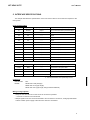
Pin arrangement table
Pin number
Signal name
Input/output (user side)
Treatment (user side)
A1
TRCCLK
Output
22 - 33 Ω series resistor (recommended)*1
A2
NC.
------
Open
A3
NC.
------
Open
A4
NC.
------
Open
A5
NC.
------
Open
A6
NC.
------
Open
A7
RMODE/JTDI
Input
4.7k - 10 kΩ pullup
A8
JTCK
Input
4.7k - 10 kΩ pullup
A9
JTMS
Input
4.7k - 10 kΩ pullup
A10
JTDO
Output
A11
JTRSTB
Input
A12
BKTGIO_L
Input/Output
A13
NC.
------
Pin number
Signal name
Input/output (user side)
B1-B10
GND
------
Connection to the power GND
B11
NC.
------
Open
B12
NC.
------
Open
B13
+3.3V
------
Connection to the power
22 - 33 Ω series resistor (recommended)
4.7k - 10 kΩ pulldown
4.7k - 10 kΩ pullup
Open
Treatment (user side)
*1: It is required when CPU (VR4122) is ES3.
Connectors
Manufacturer:
KEL
Models:
8830E-026-170S (straight)
8830E-026-170L (right angle)
8831E-026-170L (right angle, fixing hardware attached)
Wiring on Target System
1.Keep the wire from the CPU to the connector as short as possible.
>>100 mm or shorter is recommended.
2.Output signals from CPU are recommended to be connected to connectors, via high-speed CMOS
buffers of which power supply is the same one with CPU I/O buffers.
9