1
Technical Report
CMU/SEI-88-TR-003
ISTAR Evaluation
Technical Report
CMU/SEI-88-TR-003
Unlimited distribution subject to the copyright.
ISTAR Evaluation
Software Engineering Institute
Carnegie Mellon University
Pittsburgh, Pennsylvania 15213
This report was prepared for the SEI Joint Program Office HQ ESC/AXS
5 Eglin Street
Hanscom AFB, MA 01731-2116
The ideas and findings in this report should not be construed as an official DoD position.
It is published in the interest of scientific and technical information exchange.
FOR THE COMMANDER
(signature on file)
Thomas R. Miller, Lt Col, USAF, SEI Joint Program Office
This work is sponsored by the U.S. Department of Defense.
Copyright 1988 by Carnegie Mellon University.
Permission to reproduce this document and to prepare derivative works from this document for internal use is granted, provided the copyright and
\‘No Warranty\’ statements are included with all reproductions and derivative works. Requests for permission to reproduce this document or to
prepare derivative works of this document for external and commercial use should be addressed to the SEI Licensing Agent.
NO WARRANTY
THIS CARNEGIE MELLON UNIVERSITY AND SOFTWARE ENGINEERING INSTITUTE MATERIAL IS FURNISHED ON AN \‘AS-IS\’ BASIS.
CARNEGIE MELLON UNIVERSITY MAKES NO WARRANTIES OF ANY KIND, EITHER EXPRESSED OR IMPLIED, AS TO ANY MATTER
INCLUDING, BUT NOT LIMITED TO, WARRANTY OF FITNESS FOR PURPOSE OR MERCHANTIBILITY, EXCLUSIVITY, OR RESULTS
OBTAINED FROM USE OF THE MATERIAL. CARNEGIE MELLON UNIVERSITY DOES NOT MAKE ANY WARRANTY OF ANY KIND WITH
RESPECT TO FREEDOM FROM PATENT, TRADEMARK, OR COPYRIGHT INFRINGEMENT.
This work was created in the performance of Federal Government Contract Number F19628-95-C-0003 with Carnegie Mellon University for the
operation of the Software Engineering Institute, a federally funded research and development center. The Government of the United States has a
royalty-free government-purpose license to use, duplicate, or disclose the work, in whole or in part and in any manner, and to have or permit others
to do so, for government purposes pursuant to the copyright license under the clause at 52.227-7013.
This document is available through Research Access, Inc. / 800 Vinial Street / Pittsburgh, PA 15212. Phone:
1-800-685-6510.
FAX: (412)
321-2994. RAI also maintains a World Wide Web home page at http://www.rai.com
Copies of this document are available through the National Technical Information Service (NTIS). For information on ordering, please contact NTIS
directly: National Technical Information Service / U.S. Department of Commerce / Springfield, VA 22161. Phone: (703) 487-4600.
This document is also available through the Defense Technical Information Center (DTIC). DTIC provides acess to and transfer of scientific and
technical information for DoD personnel, DoD contractors and potential con tractors, and other U.S. Government agency personnel and their
contractors. To obtain a copy, please contact DTIC directly: Defense Technical Information Center / 8725 John J. Kingman Road / Suite 0944 / Ft.
Belvoir, VA 22060-6218. Phone: 1-800-225-3842 or 703-767-8222.
Use of any trademarks in this report is not intended in any way to infringe on the rights of the trademark holder.
ISTAR Evaluation
Abstract: ISTAR is an integrated project support environment produced by Imperial Software Technology, Ltd. This evaluation of ISTAR is intended for
software technologists considering the adoption of an integrated project support environment. Researchers and others interested in environments and
evaluation methods will also benefit from this report.
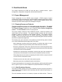
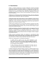
1. Introduction
This report, primarily descriptive in nature, is the result of our evaluation of the integrated
project support environment ISTAR. In the report, we present a factual description of the
facilities offered by ISTAR so that readers can draw their own conclusions. We also offer
our own conclusions and opinions of ISTAR in subsections entitled ‘‘Analysis and
Critique.’’ A brief summary of the report and the methodology used follows.
1.1. Summary of the Report
ISTAR is a software development and project management environment that integrates
management and technical development activities. It is based on the ‘‘contract model,’’
whose primary objective is that every individual in the organization know what is expected of him or her. To accomplish this, the relationships among the individuals of the
organization are modeled as contracts. Each contract has a specification of the work to
be performed under it, a person to whom it has been assigned, and a person for whom
the work is being done.
In Chapter 2 we describe the contract model both as a project management structure and
as a data storage structure. We find that the emphasis on project hygiene leads to a
strict separation of user data spaces which causes excess data storage requirements
and data movement operations. This, in turn, may make data sharing and cooperative
work more difficult. ISTAR’s user interface is also described in Chapter 2. That interface
has a high degree of consistency because all user interaction is mediated through Imperial Software’s proprietary editor, E, which is window- and menu-oriented.
Chapter 3, which forms the bulk of the report, deals with the functional areas (that is,
those tool sets supplied with ISTAR) which were of most interest to us. The remaining
tool sets are described in Chapter 4.
ISTAR’s project management tool set (ISTAR uses the term ‘‘workbench’’ rather than
‘‘tool set’’) contains tools for project estimation, description, scheduling, resource allocation, and tracking. These tools are well integrated at the data level; that is, with the
exception of the estimation tool, the output of one tool feeds naturally into the next tool in
the planning cycle. They do well at tracking resources against a schedule as a project is
executed.
The tools are not as well integrated at the tool level. This makes moving from phase to
phase unnecessarily difficult, a phenomenon which is particularly unfortunate during
replanning activities. The tools do not support group planning activities at all well and
should not be used for that purpose. The most serious criticism which can be made of
ISTAR’s planning tools is that they do not react well to change, particularly change which
occurs during project execution, such as reassignment of personnel or responsibilities.
CMU/SEI-88-TR-3
1
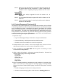
ISTAR’s configuration management support can best be described as rudimentary. There
is support for version control and little else. There is no system modeling capability as
such; there is no check in/check out paradigm; there is no support for release management. ISTAR provides a sophisticated problem-reporting mechanism but no automated
support for tying a software module version to the problems it repairs.
The ISTAR editor, E, has a syntax-directed editing mode which facilitates the entry of
Ada source code. The editor is sensitive only to static syntax; it is not aware of semantic
constraints such as type consistency and undeclared variables. Thus, a compilation unit
which passes the editor’s syntax checks may not compile. ISTAR provides a windowand menu-oriented front end to the Alsys Ada compiler, which is a considerable improvement over the text-oriented command language of the compiler itself.
ISTAR is an emerging product, not a completed one. A software development organization wishing to introduce an integrated support environment into its operation has a
variety of implementation choices. It may decide to handcraft an environment from existing and newly developed tools, or it may acquire an environment framework upon which
to build. To our knowledge, there are no environments currently available that can be
installed and used unmodified, and it is unlikely that any such environment will appear in
the near future. An organization wishing to build on an existing framework should consider ISTAR a candidate system.
1.2. Description of the Method
Our evaluation of ISTAR was guided by the environment evaluation methodology
described in [Weiderman 87]. This methodology is organized by the functional areas
supported by an environment. For each functional area, an evaluation proceeds through
six phases:
1. Identify and Classify Key Activities. Activities within the area are identified,
categorized, refined, and classified into primary and secondary functions.
2. Establish Evaluative Criteria and Associated Questions.
Specific evaluative
criteria are established and a list of questions evaluating each criterion is assembled.
3. Develop Generic Experiments. Environment-independent evaluation experiments
are developed whose execution on a specific environment provides data for the
answers to the questions developed in phase 2.
4. Develop Environment-Specific Experiments. The generic experiments developed
in phase 3 are instantiated for the object environment. The result is a sequence of
operations to be performed on the environment.
5. Execute Environment-Specific Experiments. The operations defined in phase 4
are executed. The data collected are used to answer the questions of phase 2. The
answers to those questions are the result.
6. Analyze Results. Information collected from the prior phases is assimilated. The
environment is described and analyzed.
2
CMU/SEI-88-TR-3
The first three of these phases are independent of any environment; the last three are
specific to the environment being analyzed. We used the results of [Weiderman 87] and
[Feiler 88] for the environment-independent phases. The functional areas addressed are:
• Project Management
• Configuration Management
• System Management
• Design and Development
To make this report self-contained, we have included as an appendix the outputs of
earlier phases of the evaluation methodology. Appendix A contains the generic experiments, reproduced from [Weiderman 87] and [Feiler 88]. Appendix B contains the experiments instantiated for ISTAR. We have attempted to include in that section our reasoning for implementing the generic steps as we did. Appendix C contains the output of
phase 5, the answers to the questions produced in phase 2. The questions are included
as well. The body of the report can be read without reference to the appendices. Only
readers with interest in details of ISTAR or the evaluation methodology need consult the
appendices.
Some of what we say in this report is specific to the ISTAR release we examined
(Release <2, 11, 3>); hence, if the reader acquires ISTAR, some of the statements in this
report may not be true of that release. However, we have generally avoided low-level
details of ISTAR and trust that the bulk of what we say will remain true for later ISTAR
releases.
CMU/SEI-88-TR-3
3
4
CMU/SEI-88-TR-3
2. Architecture
This chapter presents an overall description of ISTAR, concentrating on its underlying
principle—the contract model—and its user interface.
2.1. Contract Model
At the heart of ISTAR is the contract model of project organization. This model views
work assignment as the central fact in the organization and process of software development. The goal of the model is to ensure that each member of the organization has a
well-defined set of tasks which have well-defined termination criteria.
2.1.1. Project Organization
As its name implies, a contract is an agreement between two parties about a piece of
work to be performed. The client of the contract, for whom the work is to be done, issues
the contract to a contractor who is to perform the work. A contractor may perform the
work specified in the contract by subcontracting pieces of it to other contractors. The
terms client and contractor reference roles played by individuals, rather than the individuals themselves.
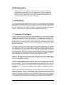
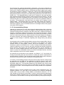
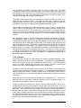
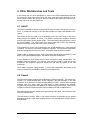
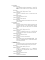
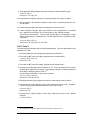
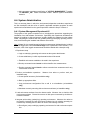
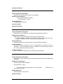
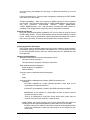
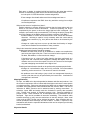
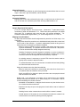
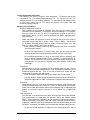
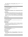
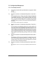
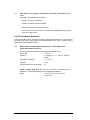
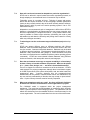
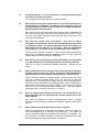
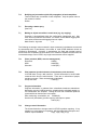
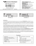
The acts of contract and subcontract assignment and acceptance force the collection of
all contracts within an ISTAR installation to form a tree. (See Figure 2-1, which is adapted
from [Dowson 87].) The topology of this tree is recorded locally; that is, each contract
maintains a record of its subcontracts and of its parent contract.
Inputs:
Specification
Deliverables
Reporting and
Outputs: Reports
Acceptance Criteria
Contract
contract
contract
contract
contract
contract
contract
contract
Figure 2-1: Contracts and the Contract Hierarchy
CMU/SEI-88-TR-3
5
On the other hand, ISTAR does not require or even suggest a software development
methodology. The division of a contractual obligation into subcontracts can be along any
lines deemed appropriate. An individual subcontract may require the execution of a lifecycle phase (design, coding, etc.) for the entire product; it may require the execution of
multiple phases for a piece of the product (functional decomposition). Different contracts
may be handled in different ways. The essence of a contract is that it is the contractor’s
responsibility to decide how to fulfill it, subject to any constraints imposed by the contract
specification or management directive [Dowson 87].
Although the collection of all contracts forms a tree, the mapping of that tree onto the
collection of ISTAR users is arbitrary. Any ISTAR user can assign a contract to any other
ISTAR user, including himself, at any time. ISTAR does not record the organization’s
reporting or management structure except insofar as that is recorded in the contract
structure. There is no notion in ISTAR of a user’s having authority to assign contracts to
other users. Therefore, when the hierarchy of Figure 2-1 is mapped onto the individuals
within the development organization, the result is a graph of arbitrary topology. ISTAR
insists that the work be decomposed hierarchically; it does not require the development
organization to be managed hierarchically.
An ISTAR contractor receives asynchronous notification of a new contract assignment;
he or she must accept this contract without being able to read it. (No capability is
provided to reject contract assignments.) Essentially, an ISTAR contract assignment is
the formal, recorded counterpart to an informal assignment of work. Communications
within or between organizations mediated by ISTAR are generally meant to supplement
informal communication channels, not to replace them. The value added by ISTAR
comes from the recording of these communications. This provides a basis upon which
the contractor, the client, and their management can understand, discuss, and track work
in progress.
As shown in Figure 2-1, the input to a contract consists of specifications and other information; the outputs are deliverables that fulfill the contract specifications and reports on
work in progress. All of these data flows can be incremental. A contract specification can
be updated after initial assignment; a deliverable can be transmitted in pieces over time.
Transmittal of a deliverable does not terminate a contract. Contracts can be canceled by
the client, in which case the contractor is informed of the cancellation. A contract can be
destroyed by the contractor at any time, without administrative control or intervention.
However, contracts are not meant to be destroyed. In fact, information on a project
should not be discarded, even after project termination. In order to save secondary
storage, ISTAR offers an archival facility. (This was not implemented in the version of
ISTAR which we examined.)
ISTAR makes no attempt to enforce any rules or standards on the data flows into and out
of the contract. When a contract is assigned, something must be transmitted as a
specification. When a delivery is made, something must be delivered. The identities of
the specifications and deliverables are recorded in the parent contract. Beyond this
recording, nothing is done to determine whether the specification is acceptable or the
delivery conforms to it. This philosophy has been called ‘‘a liberal policy, strictly enforced.’’ The enforcement occurs in ISTAR’s requiring that a specification be provided. It
is worth noting that ISTAR ‘‘freezes’’ the specification at the time it is transmitted, thereby
making it impossible for either party, client or contractor, to alter the specification. (This
does not affect the client’s ability to update the contract with subsequent specifications,
but it does prevent the text of the original specification from being modified. These
comments apply equally to deliverables.) This philosophy is justified in the following discussion of the support an environment should give to a software process.
Most of the processes that are currently employed within our industry would be
completely unworkable were it not for human ingenuity and flexibility. In prac-
6
CMU/SEI-88-TR-3
tice, people follow the ‘defined’ process until it breaks down, and then find ways
of getting round the problem. Any attempt to strictly enforce a specified process
in all its aspects is therefore likely to be counter-productive—the process will
probably emerge as unworkable [Stenning1 87].
Although ISTAR enforces no requirements on the content of specifications, it does
provide tools for their construction. These tools are encapsulated in the Project Management workbench and are fully described in a subsequent chapter of this report. They
include a software cost estimation tool, work breakdown and scheduling tools, and a
resource management tool. Through the use of these tools and a task definition tool, a
client may construct a specification that includes schedule constraints and resource lists
as well as development objectives, standards to be adhered to by the contractor, and
termination criteria to be met. These termination criteria take the form of checklists which
the contractor is meant to fill out, indicating that required quality assurance steps have
been carried out. The completed checklists are returned, with the deliverable, to the
client. In keeping with its philosophy, ISTAR does not verify the completion of these
checklists: that must be done by the client, who may examine the state of the checklist
when it is returned.
The Project Management workbench also contains tools for monitoring the progress of
contract fulfillment. The contractors submit time sheets which record effort and resources
(time and material) expended on the contract and an ‘‘estimated completion’’ percentage.
These time sheets can be summarized and sent up the contract hierarchy. The contractor
may indicate contract completion in a time sheet, but ISTAR does not verify that anything
has been delivered.
ISTAR supports a problem reporting mechanism which can be thought of as a method of
work assignment parallel to the contract assignment mechanism. Any ISTAR user can
raise a problem report at any time. These reports are predefined forms containing
problem descriptions, severity, impact, etc. Problem reports have controllers, individuals
who presumably are responsible for taking corrective action. Having raised a problem
report, a user may send the report to another user, optionally passing controllership of
the report. In effect, the reporter has assigned work to the recipient. However, for this
transmission to take place, the sender must know not merely the name of the recipient,
but also the name of the contract under which the maintenance and repair work will be
carried out. Although the specific task has been assigned outside the contract model, the
model still controls the assignment of responsibilities, e.g., maintenance, to individuals.
The problem reporting tools have their own methods for recording completion and informing the original reporter; these are separate from the methods of time sheets and
deliverables used in contract completion. This separation recognizes that, although a
specific problem has been repaired, the maintenance activity is on-going.
2.1.2. Data Organization
We have been discussing the contract model as a means of organizing the work of a
software development organization. We will now turn to a description of the model as it
affects ISTAR’s data organization and storage and its model of tool usage.
When a contract is accepted by a contractor, a new contract database is created. This
database is a large piece (actually, three pieces) of the UNIX file space which is
managed by ISTAR. Each contract has its own database that the contractor (the owner)
alone can modify.
The data model of a contract database is a variant of the ‘‘binary data model’’ [Tsichritzis
82]. Objects within the database are typed and are related to one another through named
binary relationships. Users may declare relationship (but not object) types of their own
and relate objects using these user relationships. ISTAR provides a report writing facility
CMU/SEI-88-TR-3
7
with which the user may create specialized reports from the database. The description, or
schema, of much of the data in these databases is available on line to assist in the
creation of these reports.1
For the most part, however, ISTAR users need not be concerned with, nor even aware of,
the organization of the contract databases. Access to the database is usually done
through tools which encapsulate the database interface and present a higher level interface to the user.
The purpose of the contract database within ISTAR is to be the repository of controlled
project knowledge. Information within a contract database is subject to version control,
may be ‘‘frozen,’’ and may be moved from contract to contract. When data is moved in
this way, a record is kept of that movement, making it possible to track the source of
information.
The data stored in a contract database is originally created by some other means: either
an ISTAR tool or a UNIX program. Generally, an ISTAR tool will organize and maintain
data within a special purpose work area. These work areas are specific to the tool and to
the user, but generally not to any contract. Thus, a user has access to the same information within a work area, no matter what contract he is working on. No other user may
access that information in any way. It is as though the data within a work area is the
user’s personal property, whereas the information within the contract belongs to the organization.
The user transfers information from his personal work areas to one of his contract
databases via an EXPORT operation.2 The unit of transfer is called the transfer item,
abbreviated XI. Each XI has a type which identifies the tool that exported it, although
some tools can export items of more than one type. The type of XI exported by the Ada
tools, for example, will indicate whether the item is an Ada specification or an Ada body.
The typing of XIs is used to prevent importation of an item by a tool which is not prepared
to deal with it.
Within the database, transfer items are gathered into sets called configuration items,
abbreviated CI. This gathering into sets is not recursive, in the sense that CIs may not
appear as elements of other CIs. A given XI may appear as an element of more than one
CI.
An individual XI may contain, for example, either a single program, from the Ada or
Pascal tools, a schedule, from the scheduling tool, free text, from the text tool, or a quality
checklist, from the quality assurance tool. ISTAR provides a mechanism whereby any
UNIX file may be exported as an XI to a contract. The collection of XIs within a CI will
form some logical entity: a specification for a contract, a baseline of a system, etc.
Associated with each XI and with each CI is a successor number and a variant name.
Any XI or CI may thus appear within a contract database any number of times. More
accurately, any number of CIs or XIs within a contract database may have the same
name, provided they differ in either the variant name or successor number. The collection of all instances of an XI or CI will form a tree, in which each root to leaf path
represents a parallel line of development and each node is a successor, or variant, of its
parent. ISTAR will track the relationships of variation and succession that form the edges
of such a tree. ISTAR will not, however, allow variants to be merged back into a mainline
of development. The graph must remain a tree.
1
This description is based on the version of ISTAR which we examined. Future versions of ISTAR are
planned which will implement an entity-relationship data model.
2
8
The inverse data movement is accomplished by an IMPORT operation.
CMU/SEI-88-TR-3
As the XI is the unit of transfer between the tools and the contract, the CI is the unit of
transfer between contracts. The specification which must accompany the assignment of a
contract is a CI, as are the deliverables returned in fulfillment of a contract. These are not
the only mechanisms by which information may be transported between contracts.
Provided that a user knows the exact name, including the successor number and variant
name,3 of a CI in another user’s database, he may issue a request, called RETRIEVE CI, for
a copy of that CI. The owner of the CI, which is to say, the owner of the database in
which the CI is stored, must have taken action to allow such access, which is disallowed
by default. Optionally, the owner may have ISTAR record the identity of any user taking
such a copy of the CI. These options are on a CI-by-CI basis.
ISTAR supports the concept of a library. Structurally, a library is a contract database.
Operationally, it serves not to record information for a specific task, but to act as a
publicly accessible repository. An ISTAR library may implement a library of programs,
standards, regression tests, or any collection of information at the user’s discretion. The
process of copying information from a library is a simplification of the process described
in the prior paragraph. ISTAR provides to the requester a list of the CIs contained in the
library. The requester ‘‘points’’ to the CI he wants to copy and makes his request through
a menu selection. He thus needs less a priori knowledge of the contents of the library
then he does in the case of RETRIEVE CI. It is worth noting that every XI and every CI has
an associated free text description which is created when the item is created. However,
the user of the library retrieval system does not have access to that description.
There is a specialized process for entering CIs into a library. Any ISTAR user may initiate
the process by sending a notification to the owner of the library. Recall that an ISTAR
library is a contract database and thus has an owner, as does every such database. The
owner of a library effectively serves as a librarian. The librarian reads the text of the
notification, which is a predefined form containing descriptions of the item and may contain information concerning the standards, quality assurance procedures, and tests which
have been applied to the item, and decides whether to accept or reject the item for
inclusion in the library. Therefore, the contents of a library are necessarily subject to
some degree of human quality control. This is consistent with ISTAR’s liberal enforcement policy.
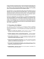
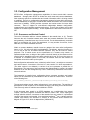
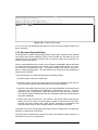
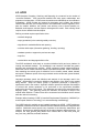
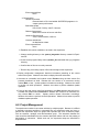
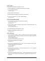
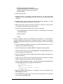
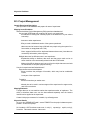
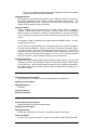
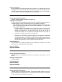
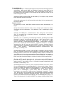
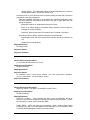
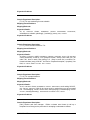
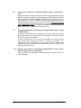
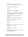
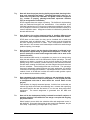
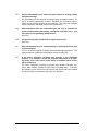
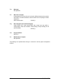
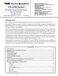
A summary of the movement of data within ISTAR among contracts, work areas, and
libraries is given in Figure 2-2.
There is yet another mechanism whereby ISTAR users may share information. The
owner of a contract may elect to allow other users to share the contract. The users
sharing a contract may each access and modify its contents as though they owned it.
ISTAR ensures that no two sharers of a contract access it simultaneously. It is worthwhile
to note at this point that an ISTAR user can access an ISTAR tool only while signed on to
or working on a contract. Therefore, no two sharers of a shared contract may be working
on the contract in any way, that is, with any tools, at the same time. A user working on a
shared contract locks out other users sharing the contract for long periods of time. Those
users may, of course, work on other contracts during those periods.
The staff of Imperial Software have indicated in conversations that they do not favor the
concept of the shared contract. Indeed, the shared contract violates the principle that the
contract is an agreement on a task to be done. However, we have seen, in the library
facility, that contract databases serve functions other than that of recording purely contractual information. The library is not the only example of such usage. The resource
3
ISTAR recognizes two symbolic successor numbers: #L (latest) and #P (preferred). These may lower the
burden of knowledge on the user in this context.
CMU/SEI-88-TR-3
9
client contract
CI
assign
contract
CI
deliver
contract
tool work area
CI
CI
retrieve ci
CI
CI
notify
CI
XI
export
XI
import
CI
scan
library
CI
CI
Figure 2-2: A Summary of ISTAR Data Movement
10
CMU/SEI-88-TR-3
management tools, used in project planning and management, store information concerning resource usage and availability in contract databases called resource management
centers or RMCs. These RMCs are, like libraries, repositories of publicly available information and, like libraries, have individual owners, called resource managers.
We have been unable to determine with precision Imperial Software’s motivation for including shared contracts, but it would appear to have been done at customer demand.
The sharing of information through shared contracts can be simpler and quicker than the
other methods previously described. ISTAR’s locking mechanism for shared contracts
makes that sharing somewhat less effective. We do not have enough knowledge or experience to have formed an opinion on the issue of shared contracts.
The databases, work areas, and ancillary files in which ISTAR stores its data are organized into a higher level structure, known by the names datatree and host. The name
‘‘datatree’’ conveys an accurate impression of the structure of these objects; they are
subtrees of the UNIX file space. Each ISTAR user has a subtree of the datatree within
which his databases and work areas appear as files and subtrees. ISTAR prevents access to the datatree by non-ISTAR programs by creating fictitious owners for the files
within the tree and preventing non-owner access through the UNIX file protection
mechanisms.
The term ’’host’’ conveys an accurate impression of the intended use of these structures;
they are used in the support of distributed operations. There is nothing to prevent an
individual UNIX file space from containing more than one datatree. A user specifies the
identity of his or her datatree through an environment variable which may be set by
appropriate shell or login procedures. However, the essential purpose of the host or
datatree construct is to implement inter-machine communication.
ISTAR allows its system administrator to specify the mechanism by which communication
between a given host and any other is to be accomplished. This mechanism can be any
UNIX program. This general mechanism can support local and wide area networks, email or other file transfer protocols, or physical transport using magnetic tape. ISTAR
users within different companies can use the ISTAR communication facilities. The authors have used them to communicate with Imperial Software. Such communication is
possible only if the companies have agreed to use ISTAR communication facilities, have
determined the protocols to be used, and know the names of each other’s hosts.
The specification, from the user’s perspective, of inter-host communication is not identical
to that for intra-host communication, but the differences are minor. When doing contract
assignment or inter-contractual data movement, the user must specify the target host
name, if it is not the local host. For contract delivery, the identity of the parent contract is
locally recorded, so this information is unnecessary. The specialized procedures for
library retrieval described earlier are not available when the library is remotely stored, and
so the requester must have complete information concerning the identity of the requested
item. These differences are not significant and not unexpected. ISTAR does not maintain
a user-datatree mapping function. Maintenance of such a map might require interorganizational cooperation, in the area of user name assignment in particular, that may
not be desirable.
The inter-contractual information transfer mechanisms within ISTAR have been designed
with remote communication in mind. For example, the request a user makes for information from a library, as described earlier, does not effect the transfer directly, even in
the intra-host case. The transfer is done by a background process or demon,
asynchronously. The requester is notified when the transfer is complete and must then
install the item in his database via a separate operation. The delay involved in these
operations is unavoidable for remote communication, but annoying in the local case. In
our own experiments, in which only local communication occurred, we found the transfer
occurred quickly.
CMU/SEI-88-TR-3
11
2.2. User Interface
ISTAR presents its users with a uniform user interface in the sense that every tool and
interface expects input and returns output in roughly similar ways. ISTAR accomplishes
this by having all user communication done through its proprietary editor, called ‘‘E.’’
This editor and the interface it presents is the subject of the following section.
The interface is modeled on the capability of a DEC VT100. It can therefore be used with
any device capable of emulating such a terminal. Imperial Software has also implemented a version of the interface under SunTools. The additional features of that
implementation are noted as appropriate. The editor is configurable at the level of key
bindings, thereby accommodating the differing interpretations of the function keys on
various terminals. This feature can also be used to make the editor more nearly
resemble an editor with which the user may be previously familiar. We have ourselves
used it in that way.
The interface is window- and menu-oriented. The display may contain any number of
windows simultaneously. These windows can serve various purposes. Some of them
contain menus. A user selects a menu item by positioning the cursor at the item, using
the cursor movement keys, and entering either a carriage return or space. Alternatively,
the user can move the cursor directly to the menu item by entering its first character, a
system which works less well for menus in which multiple items have the same initial
character. Because menu interaction, like all other interaction, is under the control of the
editor, the editor’s positioning commands (e.g., ‘‘bottom of file’’ for selecting the last item
in a menu) are available. Menu interaction is identical for all tools, as they all use the
editor to accomplish it. In the SunTools implementation, cursor positioning, and item
selection can be done directly with the mouse.
In addition to windows, the display also contains a command line. (It will generally also
contain an area reserved for the display of system status information.) Much of menu
interaction results in the execution of a command, either by the editor or the tool. Many of
these commands can also be entered on the command line, which a knowledgeable
ISTAR user may prefer, particularly when the menu interaction requires multiple level of
submenus. There is a powerful abbreviation mechanism available for the command line
and a history mechanism as well.
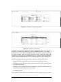
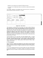
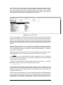
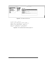
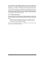
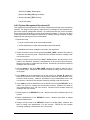
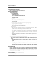
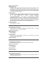
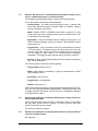
Figure 2-3 contains an example ISTAR screen. This particular screen is displayed by the
ISTAR framework. The framework is the highest level of control in ISTAR, which the
user enters after logging on to ISTAR. The command line appears at the top of the
display, at the point where the ‘‘greater than’’ sign (>) appears. The narrow window
directly below is the initial menu. In the example, the user has selected the contract
operation from that window, which displayed the large window in the lower right of the
screen; this window contains a list of the user’s contracts. The user has selected and
opened one of those contracts (CMEXP), resulting in the display of the menu on the
lower left of the screen. Selection of the workbench operation in that menu produces the
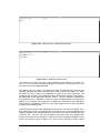
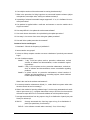
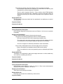
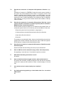
display shown in Figure 2-4. The new pop-up menu shown there lists the workbenches
currently available in ISTAR. Workbenches are collections of related tools and their local
work areas. All work in ISTAR is performed in workbenches which are initiated through
this menu. As the display indicates, workbenches are accessible only through an open
contract. Therefore, all work done by ISTAR users is necessarily done for some contract.
Some of the windows popped up by ISTAR contain forms. These are created and
manipulated by the ISTAR editor. The ISTAR tool set contains tools for the creation of
form templates, the descriptions of forms. Therefore, the forms system is directly available to ISTAR tool builders.
12
CMU/SEI-88-TR-3
Figure 2-3: A Framework Display
Figure 2-4: Another Framework Display
As the name implies, forms are electronic representations of paper forms. They have
fields containing constant information, for display purposes only, and fields containing
user modifiable information. For such fields, the form designer can specify a prompt
string which the editor will display when the form user is entering information into the
field. This string can be used by the designer to convey a brief description of the meaning
and purpose of the information to be entered into the field. The forms system includes a
validation capability for information entered into form fields. This takes the form of a
regular expression match. The form designer can specify an error string to be displayed
by the editor when the user enters information which does not conform to the regular
expression. The designer can, optionally, have the validation strictly enforced, in which
case the user will not be allowed to leave a field containing non-conforming data. If this
option has not been chosen, the ISTAR allows the user to leave such data in a field, but
displays the error message.
All ISTAR tools use the forms system for capturing parameters to commands. This includes such things as the names of XIs for transport between a work area and a contract,
for example. Some tools use it for the entry of structured data of larger volume than
command parameters. The use of this system by all tools provides a high degree of
consistency to ISTAR in this regard.
CMU/SEI-88-TR-3
13
The ISTAR editor can also act as a general purpose, syntax-directed editor. ISTAR
uses the editor in this way in the Ada workbench, among others. The language in which
the syntax is written is documented and available to the ISTAR tool builder. It is an
extension of the well known BNF (Backus Naur Form) notation for describing programming languages. The most important extensions are ‘‘layout directives,’’ which describe
and control the appearance of the document. Thus, an Ada program edited in this way
will always be ‘‘pretty printed.’’
A syntactic document, that is, one using syntax-directed editing, may contain ‘‘stubs,’’
generated by the editor that stand for syntactic categories. For example, the empty
Pascal program will appear as the stub program. The user replaces the stub with text
and the editor ensures that the replacement conforms to the appropriate category. The
user may enter part of a syntactic element. For example, he may replace the stub
statement with the term for and the editor will automatically supply the concrete syntax
and stubs making up a for-loop. The editor can also ‘‘fold’’ a syntactic construct, replacing
the text with the stub.4 This can be useful for program scanning.
The syntax direction supplied by the ISTAR editor in this mode is limited to that which can
be described in BNF. This limitation can be called ‘‘static syntax’’; it is the syntax which
can be checked locally. Items such as variable declarations and type constraints do not
fall in this category. Therefore, a program entered in this way may not conform to the
language and may not compile without error.
Many of the functions of the editor are bound to function keys. The exact set of functions so bound varies from terminal to terminal. In the Sun implementation used in this
experiment, the functions bound to function keys include some used in form and syntaxediting, as well as frequently used functions of simple text editing. The availability of
these functions on keys was extremely useful.
The most frequently used and useful of the functions are, in the Sun case, bound to the
top row of keys.5 The utility of these keys is such that they are worth discussing individually.
• POP. This key is used to discard windows. It is particularly useful for aborting interactions in midstream.
• WIDE. This key is used to control the size of windows.
• LOCAL and HOUSEKEEPING. These keys cause the display of menus of commands. The
contents of these menus depend upon the context in which the keys are pressed. The
housekeeping menu contains commands specific to a given workbench. No matter
what the user is doing within in any tool of the workbench, this menu’s display
remains constant. The menu varies from workbench to workbench. Generally, the
command to exit the workbench appears in the housekeeping menu.
The commands in the local menu vary with the tool being used. The commands are
also specific to the state of the user’s interaction with the tool. For example, in the
component management tool, which is concerned with the elements of a contract
database, the local menu contains a command to create a new CI when the interaction is in a state in which no CI has been selected. In a state in which a CI has
4
The difference between a folded construct and one which has not yet been entered is made clear on the
display.
5
In the SunTool case, these appear as mouse selectable buttons on the display. They are also available as
escape sequences, even on terminals without function keys.
14
CMU/SEI-88-TR-3
been selected, the local menu contains a command to create a successor of the
selected CI.
• HELP. This key invokes the context-sensitive help system.
• VALIDSET. This key is used for filling in form fields. It causes the display of a menu
containing items which can validly be entered into the field. For example, during the
specification of an import operation, the VALIDSET key will display a list of all XIs which
can be imported from the contract into the work area. The user may use menu selection techniques to select an item from this list.
• CONTEXT. The project management tools use this key to switch between different
views of their database. For example, the structure of a product within an activity can
be displayed by focusing on the product (that is, moving the cursor to it) and pressing
the CONTEXT key.
2.3. Analysis
An analysis of ISTAR’s contract model and user interface follows.
2.3.1. Contract Model
The contract model is designed so that each user operates within an environment that
cannot be changed without his knowledge and acquiescence. Furthermore, this environment (which is to say, the information available to the user and the names by which that
information is known) is organized, in part, according to the tasks the user performs. The
organization which implements this strategy leads to a degree of fragmentation which has
unfortunate consequences.
For example, an Ada programmer creates compilation units within the Ada workbench.
The name of the compilation unit, within the workbench, is identical to the Ada name of
the compilation unit. The workbench’s work area is completely private to the user, so in
order to make the compilation unit publicly available, he must export it to a contract
database. This causes a copy of the unit to be made. The syntax of names within a
contract database does not conform to Ada name syntax. Thus the unit is likely to have a
different name when exported. The date and time of the export is recorded in the contract
database, but it is not recorded in the workbench. It is relatively easy for the work area
version and the database version of the unit to diverge inadvertently. The fact that version control is available only for items in the contract database makes it more difficult for
an Ada programmer to work on several versions of a system simultaneously6 or to
produce experimental versions of a unit. In order to use the version control facilities, the
programmer must pay the penalty of exporting and importing. The division of an individual user’s storage into contracts and work areas results in excess data storage,
excess data movement, and an excessively large name space.
The same can be said of the separation of the individual user’s storage from each
other’s. The sharing of information becomes more difficult. Recall that all work in ISTAR
is done within work areas which can be accessed solely by their owners. For control of a
product or document to be transferred from one user to another, the following steps must
be taken: The owner of the item must export it to a contract database and must make the
item publicly accessible. The owner must inform the recipient of its name and location.
6
In the case of Ada, variants of a system will need separate Ada libraries. The ISTAR Ada workbench
supports that concept rather well.
CMU/SEI-88-TR-3
15
The recipient must then issue a request for a copy of the item, and then wait for the copy
operation to take place.7 The recipient must then install the item into one of his contract
databases and, finally, export the item into the appropriate work area. The recipient is
now able to begin work on it.
In the case of local transfer, that is, within the same ISTAR host, the above steps take
very little time. There is, however, a good deal of manual intervention and of data replication involved. In the case of remote transfer, much of that intervention, and certainly the
data replication, is unavoidable. Local transfer would seem to be much more prevalent.
The separation of users’ storage has an effect on global project knowledge. In the above
scenario, the fact of the transfer will be recorded in the recipient’s database, as a
property of the transferred item. Optionally, the original owner may have that fact
recorded in his or her database as well. Suppose that item must be forwarded to a third
user. As it turns out, ISTAR does not record the identity of the original owner in the new
recipient’s database. The history of movement of this item, and of its modifications at
each location as given by the version trees, is recorded by the system as a whole. It
cannot, however, automatically be gathered into a single location or report. This is because each contract is accessible only by its owner. No report, including those defined
by the users, can access databases owned by anyone other than the person running the
report. This makes the production of ad hoc, user-defined management reports difficult if
not impossible to accomplish.
The ISTAR model works best when a development project is well planned in advance
and the resulting plan is executed without modification. Planning is certainly a vital component of successful development projects; however, few plans, particularly for large
projects, are ever executed without modification. Unforeseen events necessitate replanning. Engineers often find their responsibilities change in mid-course. This may not
be desirable, but it is often unavoidable. The scenarios just described are realistic implementations of such mid-course changes in ISTAR.
2.3.2. User Interface
We have described the consistency of the ISTAR user interface. We must also describe
the interface’s inconsistencies. These are annoying, but not inimical to the successful use
of ISTAR. The claim that ISTAR has a consistent user interface is justifiable. Still, the
inconsistencies are worth reporting.
The presence of two function menu pop-up keys, the ‘‘local’’ and ‘‘housekeeping’’ keys
described earlier, has unwanted side effects. We found that the we frequently forgot in
which of these menus, or their submenus, a given operation was to be found.
We have reported that many of the commands available from menus are also available
on the command line. Not all such commands are so available and it is frequently impossible to guess which are and which are not. Also, the same command is handled differently in different tools.
The validset and help keys are not implemented everywhere they might be. This is not a
comment on the user interface but rather on the state of development of the tools.
We should point out that our pattern of using ISTAR may have made these inconsistencies more obvious than they would be to an average ISTAR user. As our use of
ISTAR was experimental, our interest was solely in ISTAR, with no interest in the
7
This happens asynchronously, in the ‘‘background.’’ The recipient is free to do other work while waiting for
the transfer.
16
CMU/SEI-88-TR-3
products being developed in the experiments. Movement from tool to tool was more
frequent and less time was spent in each tool than would be spent by a productionoriented user. As mentioned, these inconsistencies are merely annoying and have no
significant effect on the use of ISTAR.
CMU/SEI-88-TR-3
17
18
CMU/SEI-88-TR-3
3. Functional Areas
This chapter describes the ISTAR tool sets that were of greatest interest:
management, configuration management, and the Ada Workbench.
project
3.1. Project Management
Project management is one of ISTAR’s major strengths. ISTAR’s support of project
management includes estimating effort, developing plans, assigning personnel to perform
work, tracking progress, and verifying quality. ISTAR provides linkages between these
elements to provide coherent project-level management support.
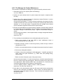
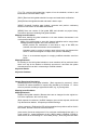
3.1.1. Planning Process and Products
The project management process can be described by roles and products. The project
manager manages the development of the work breakdown structure and schedule.
The resource manager controls the use of resources within resource management
center’s. The cost controller monitors on-going projects.
The project manager creates the work breakdown structure, creates the schedule, and
issues tasks from the schedule. The project manager interacts with the resource
manager by asking for resources to fulfill schedule activities. The resource manager
assigns resources so that there are no conflicts among plans submitted by project
managers. The cost controller interacts with all the people assigned contracts and tracks
their efforts on particular assignments.
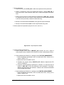
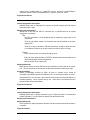
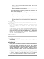
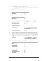
The following are quick summaries of the products processed during project management. More detailed descriptions appear later in the report.
• Work breakdown structures specify the hierarchy of activities that need to be performed to complete the project and the product flows between the activities.
• Resource management centers store physical resources to fulfill assignments within
work breakdown structures. The centers record resources which have been allocated
and resources which are still available.
• Schedules are processed work breakdown structures that specify the calendar time
and resources to be allocated for each of the work breakdown structure activities.
• Task assignments are the results of assigning scheduled activities to people selected
from the resource management center.
• Timesheets are the raw data used to track project progress.
• Monitoring reports are consolidated timesheet submissions.
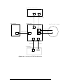
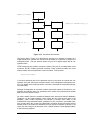
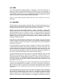
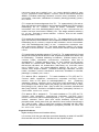
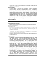
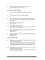
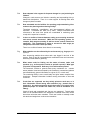
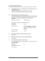
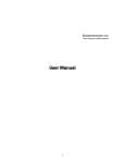
A pictorial representation of the interaction of these products, and the tools which process
them, is given in Figure 3-1 which is adapted from [Imperial Software Technology 87].
3.1.1.1. Work Breakdown Structure
The project manager specifies in the work breakdown structure the project’s activities in
terms of what is to be completed, without specifying who will actually be performing it, or
when it will be done.
The work breakdown structure is a hierarchy of parent and child activities. These ac-
CMU/SEI-88-TR-3
19
Specification From Client
Report to Client
Work Breakdown
Structuring Tool
Work Breakdown Structure
Resource
Mgmt
Center
Scheduler Tool
Schedule
Monitoring Tool
Task Definition
Tool
Contract Specifications
to Contractors
Reports From
Contractors
Figure 3-1: Project Management in ISTAR
20
CMU/SEI-88-TR-3
Timesheets
tivities logically partition large tasks into smaller units whose union forms the solution.
Each activity in the work breakdown structure specifies (paraphrased from [Dowson 87]):
• A small prose description of what the activity is supposed to accomplish.
• A list of products the activity requires to produce its products.
• A list of products produced.
• The types of resources needed to perform on the activity. The specification in the
work breakdown structure is an abstract request for resources that have specified
attributes.
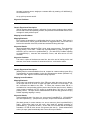
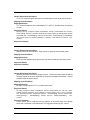
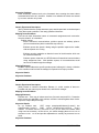
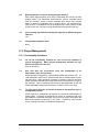
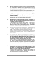
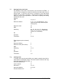
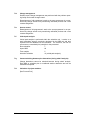
Activities are entered one at time into the activity hierarchy. Each activity’s definition is
entered onto a few panels or ‘‘views.’’ Movement from view to view is accomplished via
cursor movement and the CONTEXT key.
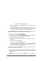
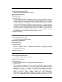
The activity view (see Figure 3-2) describes the activity, names the products produced
and needed by the activities and the resources it requires.
Product descriptions are entered into product views, an example of which appears in
Figure 3-3. Like activities, products can be decomposed hierarchically. The product flow
from activity to activity is used by the scheduler to find an executable sequence of activities.
The resource view defines the properties of the resource necessary to accomplish the
activity (see Figure 3-4). These properties are attribute, effort, utilization and tag information. This detailed information will be matched by the scheduler against similar
descriptive information of available resources in the resource management centers.
Figure 3-2: Work Breakdown Structure Activity View
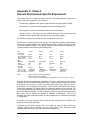
A resource attribute defines the capability and level of experience that are needed to
accomplish the activity. Attributes have the form [skill, rating] where, for example, skill is
knowledge of UNIX, and rating is a level from 1 (novice) to 10 (expert) of how well the
person knows UNIX.8 The attribute panel includes [unix,5] if a person with moderate
knowledge of UNIX is needed on the activity.
8
ISTAR allows any text string to be entered as a rating. We felt that a number scale, as reflected here, was
more appropriate.
CMU/SEI-88-TR-3
21
Figure 3-3: Work Breakdown Structure Product View
Figure 3-4: Work Breakdown Structure Resource View
Effort is the number of man-hours necessary for the resource to complete the activity.
Effort differs from calendar time because a resource can be utilized part time. (Note the
‘‘%util’’ field in Figure 3-4.) Specification of effort instead of actual time permits the
scheduler to determine the actual time the activity will take. An initial estimate of an
activity’s actual time is effort times 1/utilization.
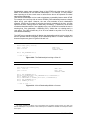
Estimation of the effort required to complete activities is provided by a tool based on the
COCOMO model. Currently there is no automated connection from that tool to either the
database or to the WBS. Figure 3-5 shows an activity in an embedded system that has
been assigned a given number of delivered source instructions. The body of the input
consists of the levels of the different cost-drivers. Boehm’s book [Boehm 81] describes
the meaning of each of the drivers. The derived person-months in Figure 3-6 can be
entered by hand into the work breakdown structure effort specification.
The resource name given in the ‘‘resource requirement’’ field of Figure 3-4, is unique to
the activity. No two activities in the structure may require the same resource. However, a
resource requirement may be given a tag and a name. A resource tag is used to collect a
set of requirements into a family. All requirements with the same tag, which are automatically listed in the appropriate panel of Figure 3-4, will be assigned to the same physical
resource. The identity of that resource will be determined when the structure is
22
CMU/SEI-88-TR-3
Figure 3-5: Estimation Tool Activity Definition
Figure 3-6: Estimation Tool Results
processed by the scheduler against the resource management center. The name of a
resource in a resource requirement of a work breakdown structure is the name of a
physical resource in the resource management center. By naming a resource in this way,
the project manager makes the resource allocation himself, rather than allowing the
scheduler to do it from the pool of available resources. Tags and names are facilities by
which the project manager can restrict the allocation of resources by the scheduling tool.
The work breakdown structure tool provides a collection of reports. These include:
• Hierarchy reports giving the structures of the activity and product hierarchies.
• Dependency reports, giving the product flows from activity to activity, organized either
by product or by activity.
• Summary reports, giving all information on activities, products or resources and a full
report which combines the three summary reports.
• A consistency report.
The consistency report contains such information as activities which do not have a parent
CMU/SEI-88-TR-3
23
(there should be exactly one of these); activities which either do not produce or do not
consume any products; and products which are either not produced or not consumed by
any activity. The project manager can examine this listing and determine whether the
information it contains represents errors in the structure definition.
The work breakdown structure tool is rather cumbersome to use. The user interacts only
with a small piece of the structure, a single activity, product, or resource, and never with
the structure as a whole. IST recommends that the work breakdown structure (WBS) be
sketched on paper before being entered into the tool [Imperial Software Technology 87].
Movement from item to item can only be accomplished navigationally. There is no way to
move directly from one item to another. For example, to move from a product to a
resource description, it is necessary to first move the cursor to an activity producing or
consuming the product, press the CONTEXT key to select an activity panel, find an activity
requiring the resource (VALIDSET helps here), move the cursor to the resource name, and
press the CONTEXT key again. This is an annoying procedure.
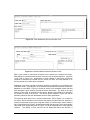
3.1.1.2. Resource Management Centers
Resource management centers contain physical details of available resources. The
work breakdown structure contains the abstract specification of the needed resources to
accomplish activities. The scheduler matches the two.
A resource manager is assigned responsibility for each resource management center.
The creation of resources to be placed initially into the resource management center is
accomplished with the definition tool. The acceptance of requests and arbitration between conflicting requests is performed with the control tool.
Definition (see Figure 3-7) involves assigning names to physical resources, categorizing
them as either RATE or TOTAL resources, and assigning them attributes in the same
manner as in the work breakdown structure entry. RATE resources are non-consumable
and available in units such as 8-hour days. People are RATE resources. TOTAL
resources are consumables that are available in units such as 10000 sheets of paper.
Attribute matches during scheduling result in resource allocation.
An internal allocation is an assignment of personnel to non-project activities. It is the way
in which training and vacations are accommodated.
Resource requests (see Figure 3-8) are sent to the resource management centers where
the resource manager uses the control tool to first read the requests, provisionally accept
them to examine the new request’s introduction of conflicts over resources, and accept
them as assigned to the schedule that requested them. Conflicts arise if more than one
schedule requests use of the same physical resource for the same time period and the
total effort exceeds 100%. Full acceptance is not performed in the presence of conflicts.
There is no mechanism to report to the project manager that a resource request has
been denied. The resources required by a project must either be granted or denied as a
whole. The resource manager does not have the freedom to grant some of the requested
resources to a project while denying others.
Creating a resource management center is an expensive operation. It took 33 seconds
to create a resource management center, while it took only about 20 seconds to enter the
tool on a center when it already existed.
24
CMU/SEI-88-TR-3
Figure 3-7: Resource Definition
Figure 3-8: Resource Control
3.1.1.3. Schedules
Scheduling matches work breakdown structure activities and available resources in the
resource management centers. Schedules first determine the begin and end dates of a
project as if there were no resource limitations. Physical resources and people from the
resource management centers are assigned to perform each activity in the work breakdown structure.
The dates permissible for the begin and end of the project are limited to those defined to
ISTAR in its global calendar. The calendar information is specified by the ISTAR system
administrator using an E structure-editor template. The work day’s duration is input along
with work and non-work time. Work time for each year, for example, would be the normal
5 work days in the U.S. but could be different in other countries. Weekends and holidays
for each year are allocated as non-work days. Non-work durations are correctly passed
over by the scheduler.
The following detailed steps produce a schedule (derived from [Imperial Software Technology 87]):
Activity Network Formation: The activity network is formed automatically when the work
CMU/SEI-88-TR-3
25
breakdown structure is read into the scheduler’s work area from either the WBS work
area or the contractual database. The network records the dependencies among the leaf
activities of the work breakdown structure, which are derived from the product flows
among those activities. The leaf activities of the work breakdown structure are those
which do not have children. The non-leaf activities are discarded by the scheduler and do
not appear in the activity network or in any subsequent outputs of the project management tools.
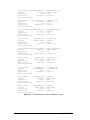
Time Analysis: The user supplies the earliest start and latest finish dates for the project
and, optionally, for each of the activities in the network. The time analysis tool then
schedules the project in conformance with those dates, if possible. This is resourceunlimited scheduling in that it assumes all resources will be available when needed. The
output of this step is available in a variety of forms including a Gantt chart, critical path
analysis, and a summary which is illustrated in Figure 3-9.
Figure 3-9: Schedule Summary After Time Analysis
Resource Limited Scheduling: This is the final type of scheduling and involves matching
the work breakdown structure against the resources in the resource management center.
Resource limited scheduling results in a more constrained schedule than that of time
analysis. Adding resource constraints only serves to limit capability to accomplish tasks.
The scheduler is given the names of resource management centers that it is allowed to
draw upon. A request for physical resources to the resource management centers is
initiated and results in the creation of a resource pool, local to the scheduler, of those
actual resources whose attributes match those of activities’ requirements. Scheduling
may then be done in either interactive or batch mode. Even if time analysis results in an
acceptable schedule, resource limited scheduling may not. The scheduler offers two
techniques for dealing with this situation: resource modification and interactive scheduling.
The attributes of resources required by the project may be altered. That is, the user
performing the scheduling task may decide that a particular resource need not have a
particular attribute or skill or need have it to a lesser degree. The user can neither delete
resource requirements nor alter the effort estimates. He or she can edit the descriptions
of the available resources in the resource pool. Specifically, he can:
• Alter the availability of the resource (e.g., allow for overtime).
• Alter the attributes of the resource.
• Alter existing allocations of the resource.
26
CMU/SEI-88-TR-3
These modifications are all hypothetical. They are not automatically entered in the
resource management center. Such modification requires communication with the
resource manager outside of ISTAR.
If a work breakdown structure is scheduled by the scheduling tool in batch mode, the
attributes of resource requirements will be exactly matched and the constraints imposed
by resource tagging and naming will be observed. The scheduler’s interactive mode
allows the person performing the scheduling task the freedom to modify this behavior.
The scheduler will display resources having the necessary skills, but not necessarily
matching the ratings. An interactive choice among these resources can then be made.
Once a schedule has been constructed, the resource management centers are sent requests for the matched resources. The resource management center control tool is used
to mediate multiple requests, as described in Section 3.1.1.2.
3.1.2. Task Management
The task definition tool transforms scheduled activities into executing contracts. The
schedule contains information derived from the work breakdown structure, resource
management center, and scheduling processes. The tool will display this information so
that it can be used when an activity is issued as a task. The issuing of a task is exactly
the assignment of a contract. Contracts are accepted by the contractor, who eventually
responds to the contract with a delivery. During contract execution, assignments can be
updated or canceled by the client. During execution, the contractor sends timesheets to
the issuing contract, for consolidated reports in combination with other timesheets.
Completion of contracts is often verified with quality assurance checklists. The quality
management workbench can be used to accomplish the review and check off of itemized
lists of required quality factors.
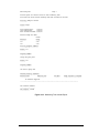
3.1.2.1. Assignment
The natural method of executing a plan is via task assignments derived from the
schedule. The schedule is the central input to the task definition tool.9 The following
fields shown in Figure 3-10 are added to the assignment in the task definition tool:
• Task ID, job code (interactively specified): Unique numbers which identify the assignment. The job code is used for timesheet reporting.
• Activity (from work breakdown structure): An activity name from the schedule. This
field is most easily input via VALIDSET. VALIDSET provides a list of activity names from
the schedule, one of which can be selected.
• Start and end dates (from schedule): Retrieved from schedule upon selection of activity.
• Status fields: Cannot be altered by user; filled in by system. Date raised and issued.
Whether it has been superseded, canceled, or signed-off (completed). Also indicates
whether the contract was assigned to oneself, or sub-contracted to someone else.
• Reporting: List of expected reporting by the contractor to the client. May include
timesheets.
• Standards: List of expected standards to be adhered to in fulfilling the contract.
9
The task definition tool may be used without the work breakdown structure and scheduler tools.
CMU/SEI-88-TR-3
27
• Objectives: List of objective to be achieved in fulfilling the contract.
• Verification: List of conditions that must be true before the contract can be considered
complete.
The standards, objectives, and verification items may take the form of references to
quality assurance checklists. See Section 3.1.4, below.
Figure 3-10: Task Definition
Task assignment is performed after the information in the above described fields has
been entered. The LOCAL function ‘‘issue task assignment’’ prompts for the fully qualified
name of an transfer item into which the information from Figure 3-10 will be placed. The
configuration item within which that transfer item appears will have already been constructed and contain whatever documents and information the contractor will need to
complete the assignment. These might be code, test cases, checklists, requirements,
specification or design documents, etc, or references to such things. The ‘‘issue task
assignment’’ local function also prompts for the name of the ISTAR user to whom the
contract will be assigned. The configuration item mentioned above is sent to that user as
the specification of a contract.
The task definition tool user is the client of the newly assigned contract. The client
names the contract, and the contractor is free to choose a different name when accepting
the contract. The task definition tool allows a client to assign a contract to himself. This
provides a mechanism for partitioning work. A sub-contracted or self-assigned contract’s
status is maintained at the client. Possible statuses include issued but not begun, begun,
complete, and canceled.
3.1.2.2. Acceptance
After the contractor is notified of the appearance of a new contract, he may accept and
rename it. He may not read the contract before acceptance and has no ability to reject it.
ISTAR assumes that contracts do not appear spontaneously but rather are anticipated by
the contractor.
A copy of the configuration item sent by the client is placed in the newly created contract
as the contract specification. The contractor accesses the information from the work
breakdown structure, the scheduler, and the task definition tool through the task definition
tool.
28
CMU/SEI-88-TR-3
3.1.2.3. Update, Cancel
The contractual relationships between clients and contractors are formed once an initial
assignment has been accepted. ISTAR permits updates to the formal task definition or
total cancellation of the contract. The contractor can not terminate the contract from his
end.
Updates to a task are specified by using the same jobcode and activity name, but a
different task id. Existence of an incoming update to the contractor is flagged in the
framework, against the original contract’s name. The contract registers acceptance in the
framework.
Cancellation is also performed from the task definition tool and is registered by the contractor in the framework.
3.1.2.4. Deliver
Assuming the contractor has performed the technical aspects of the contract, completion
is signaled by the delivery of a configuration item to the client. Acceptance of the delivery
in fulfillment by the client is acknowledged with a signoff in the task definition tool. This
concludes a formal contract.
3.1.3. Tracking
Once projects begin execution, clients wish to track how resources are being used and
how progress is being made toward completion. Timesheets sent by contractors to the
clients gather raw data. Monitoring tools at the client consolidate multiple timesheets into
reports. Summary information can also be sent to superior clients.
3.1.3.1. Timesheets
Timesheets are filled out by contractors using the timesheet reporting tool. Timesheets
are submitted weekly in the ISTAR model, and specification of the expected timesheet
submission data is stored in the ISTAR’s startup script for each installation.
Timesheets are entered on a E editor form. There are columns for contract, activity, job
code, and time spent per day. An automatic total per activity is maintained horizontally.
Per day totals are maintained vertically. Input is made by hand. An example appears in
Figure 3-11.
Figure 3-11: A Timesheet
Progress comments for particular tasks are entered in a pop-up window. Estimated date
CMU/SEI-88-TR-3
29
of completion, status of the activity as complete or incomplete, and textual comments can
be entered.
Resource usage is logged on a pop-up form that is keyed on resource names within
resource management centers. Utilization is again allocated on a per day basis.
Timesheets are submitted against cost control centers. Cost control centers at the clients
store timesheet submission from multiple subordinates and consolidate entries (see
below). When a timesheet is submitted, it is verified for: correct activity names, correct
activity-job code pairs, and the existence of a filled in progress report for each activity.
Submission changes the status of a timesheet from ‘‘unsubmitted’’ to ‘‘awaiting approval.’’ Approval of the timesheet by the client is described below.
3.1.3.2. Monitoring and Cost Control Centers
The monitoring tool is ISTAR’s method of consolidating numerous timesheets from a
client’s contractors into unified reports that track actuals against projected schedules.
The monitoring process is dependent on being able to store timesheet submissions in a
local database. The monitoring tool creates a cost control center when it is first given a
new schedule. The new schedule provides the tool with the activity names and job-codes
that will be charged against by timesheet submissions. Pooled data reports can also be
input to a monitoring session from lower-level monitoring reports sent to superiors.
Numerous reports can be generated from these data: status reports, actuals report (see
Figure 3-12), full activity report, brief activity report, full resource report, brief activity
report, and an exceptions report that highlight exceeded user-defined limits for consumption or duration.
Monitoring is one of two (the other being the resource definition) tools which have serious
performance problems. Times of 45 seconds were observed for the task of obtaining
monitoring tool input. Lesser times of 11 seconds were also observed. The task of
incorporating external timesheet submissions into an internal database and consolidating
the new data with old entries is clearly a demanding activity. The discrepancy between
the numbers can possibly be attributed to variation in the amount of data to be incorporated. Creating full activity reports in the monitoring tool also took from 45 to 18
seconds based on the amount of data being manipulated.
3.1.4. Quality Checklists
ISTAR contracts are formal requests for action and are not enforcement mechanisms.
Quality checklists can, however, be one of the items mentioned in a contract’s task
description. Checklists could be included in the task definition panels ‘‘verification’’ or
‘‘standards.’’ Quality checklists are manipulated by creating, storing, and completing
them.
The quality assurance workbench contains multiple named work areas. The work areas
contain quality checklist forms. Each checklist is a sequence of check lines. Each check
line is identified by a label and whether it is a ‘‘criterion’’ or a ‘‘reference’’ to another
checklist within the work area. The body of a criterion check line is a description of what
is to be checked for quality. The body of a reference check line is the name of another
checklist within the work area. Thus, a hierarchy of checklists is created.
The collection of checklists in a work area can be saved. If the check lists are meant to
be used by a number of project members to assure project quality, the work area can be
placed in a library. Project members may then use the library transfer facilities to get
copies.
Checklists are completed against configuration items or transfer items. Before the lists
30
CMU/SEI-88-TR-3
Monitoring Tool
Page 1
Actuals report for contract errors on 8th of February 1988
Activities for which resource bookings have been received for 16/01/87
Activity: pmexp!t1l:t1team
-------Status: begun
-----First booking date:
12/01/87
Last booking date:
12/01/87
Best end date estimate: 23/01/87
Resource usage this week:
Actual
Usage
-----4.00
4.00
Resource
-------t11
t12
Activity progress comments
-------------------------Author: t11
------Progress comment
---------------things are going well.
Author: t12
------Progress comment
---------------the work is going well
Personal activity estimates
--------------------------Resource user
Resource used
------------------------no estimates supplied
End date
--------
Usage required to complete
--------------------------
-------------------------------------------------------------------------------------
Sub-contract comments
--------------------Sub-contract: t1team
-------------
Figure 3-12: Monitoring Tool Actuals Report
CMU/SEI-88-TR-3
31
are compared against an item, lists can be tailored. Editing the checklists permits content changes to be made, while customizing them permits whole check lines status’ to be
marked ‘‘NOT APPLICABLE.’’ Reviewing a form is the central activity of checklists. Only
the status field can be changed (when comparing, the criteria are fixed). The values
assigned to each reviewed criterion are: pass (item under review has passed the
criteria), fail (the item under review has failed the criteria), requires action. The requires
action category can be upgraded to pass if the actions described in a pop-up window are
performed first. Subordinate checklists that contain any not set, requires action, or fail
status check lines, make the superior reference fail. Otherwise the parent passes. The
hierarchical evaluation method is applied recursively towards the root of the checklists.
3.1.5. Analysis and Critique
Designed for projects with one planner, ISTAR’s planning tools do not support group
planning activities. They do not react well to change after project initiation. However,
they do offer extensive support for project planning and project execution tracking.
3.1.5.1. Planning and Tracking
ISTAR’s planning facility envisions one main project manager performing a project’s planning. The manager performs the work breakdown structure layout, subsequently
schedules it against the resource management center, and makes assignments. The
manager sees the complete project and allocates programmers from the resource
management center to the lowest planning level. The model becomes fragile when the
manager wishes to solicit development or review assistance from his team leaders. ISTAR makes assistance difficult because there is no method to merge contributions or
comments back into the work breakdown structure. The ability to add to the work breakdown structure is critical since the work breakdown structure feeds the schedule,
resource management center, and task-assignment planning cycle.
One method to obviate the need for merging, is to linearize access to the work breakdown structure. In this technique, the manager constructs an initial trial work breakdown
structure and places it in a configuration item which he or she makes accessible to
project leaders. The first leader retrieves the configuration item and can access and, if
necessary, modify it using the work breakdown structure tool, creating a successor in his
contract database. That item is then made accessible to the next leader in line, who
repeats the process. Serialization can also be interactive between the manager and each
team leader so that the manager can confirm modifications.
Another coordination possibility has each team leader commenting in parallel on disjoint
portions of the work breakdown structure. The leaders would be working on numerous
copies of the original manager’s configuration item. However, there is no merging at the
manager’s level, and the manager would have to manually update each portion of the
master work breakdown structure.
Both of these solutions to the group planning problem are tedious. Group planning activities are best done offline and the completed work breakdown structure entered in one
location. This is in keeping with ISTAR’s basic philosophy of formally recording informal
communications.
Once a definitive work breakdown structure has been established by the project
manager, it evolves into a schedule. A multi-leveled work breakdown structure results in
a schedule containing only the bottom layer leaf node activities. The intermediate levels
of the activity and product hierarchies are used to deduce the dependencies among the
leaves, but the other information associated with those products and activities, their
descriptions and resource requirements in particular, are lost in the schedule.
32
CMU/SEI-88-TR-3
Assume for the moment that the project manager supervises a group of team leaders,
each of whom supervises a group of programmers. If the project manager uses the task
definition tool to directly assign the activities of the schedule, the resulting contract hierarchy will be flat; each of the contracts will have the manager’s contract as its parent; the
structure of the organization will not be reflected in the contract hierarchy. This has an
effect on the cost control and timesheet reporting mechanisms. These mechanisms can
only be used on contracts which have been created by the task definition tool from a
scheduled work breakdown structure. Timesheets must be sent to a cost control center
which contains the schedule from which the reporting contract was defined. Thus, if the
manager directly assigns contracts from the schedule, the intermediate supervisors will
be bypassed and will not be able to track the efforts of the programmers who work for
them.
One method of circumventing this problem is for the project manager to assign management tasks as contracts to her team leaders. The project manager should include the
schedule as a transfer item within the configuration item which forms the specification of
that contract. The team leaders can then import the schedule into the task definition tool
and assign activities from it to their programmers. Timesheets will then be sent to them
by their programmers. It is best if the work breakdown structure contains management
activities as leaves. The scheduler and task definition tools can then be used to assign
these management contracts and the project leader can receive timesheets from team
leaders.
The schedule can also be sent to a cost control clerk who can use it within the monitoring
tool, the tool which accepts timesheets, thereby relieving the technical management from
that responsibility.
Another technique for dealing with this problem, which we used in our instantiation of the
project management experiment, can be called the ‘‘level-by-level’’ approach. In this
technique, each manager plans only the activities of his or her immediate subordinates.
The project as a whole develops into a hierarchy of activities as each person adds more
subordinates and their activities. This development model is ‘‘lazy’’ project management.
All persons are expected to contract for further support, at their own discretion and when
they deem necessary. The level-by-level approach forces the planning hierarchy, now
only one level deep, to be identical to the contract hierarchy. The timesheet reporting
hierarchy is likewise identical to the contract hierarchy. Monitoring tool reports exactly
follow the contracting hierarchy and thus up the planning hierarchy.
A number of advantages and disadvantages accrue from limiting planning to a level-bylevel approach. Advantages having to do with replanning activities are described in Section 3.1.5.2, below. A major disadvantage is that no one person is acting as project
manager. The project cannot be scheduled as a single entity. Resources are not allocated to the project as a whole but to its sub-activities. Conflicts are more likely and
more difficult to resolve. It is difficult to ensure that the various sub-schedules correctly
interrelate.
When the project is planned and scheduled in its entirety, the project manager interacts
with the resource manager to arrive at an equitable use of personnel by exchanging
comments on the total allocation of people to the project. In the level-by-level approach,
each leader competes against all other leaders for programmers. Level-by-level planning
promotes great tensions between planners. To alleviate the tension, multiple resource
management centers could be created and one assigned to each leader. A benefit of
such an approach is that each leader is independent of other leaders and thus can perform planning and resource allocation without interference. But this method is demanding. It requires that the organization partition the company’s personnel to each manager
and team leader in a strict hierarchy ahead of time.
CMU/SEI-88-TR-3
33
Not all projects are organized hierarchically. Alternatively, work may be assigned to a
group of equally capable programmers who determine among themselves how to divide
up the work to fulfill the leader’s request. ISTAR does not directly support such cooperation because a contract is issued to a single user. There are two options and they both
result in the imposition of a hierarchy. The first option is that one of the programmers be
designated the leader of the group; not a leader among themselves but a leader from the
outside view. The designated person could receive contracts for the group and then,
after negotiation with his partners, assign the other programmers their portions. The lead
programmer would then consolidate the work of the group to form the combined result.
The second option is to create a fictitious person who acts as a hypothetical leader for
the group. The programmers could take turns in the leader role by logging in as the
fictitious leader. The decisions about who contributes what products are enacted by
assigning contracts to the individual programmers. Note, though, that both of these options have resulted in a return to the basic structure of a manager, leaders, and programmers which ISTAR supports.
3.1.5.2. Accommodating Change
Changes to a project plan can occur either during the planning stage, that is, before the
project begins execution and a contract is assigned, or after the project has begun and
contracts are being executed. Changes of the latter class, that is, changes during project
execution, can either be changes to the content or the structure of the project. Content
changes are those which affect the specification of the product and therefore are alterations to the work being done by the project members. Structural changes are changes in
the project personnel, their reporting relationships or their task responsibilities. ISTAR’s
reaction to these changes is described, beginning with changes during the planning
stage.
As mentioned earlier, the initial work breakdown structure is best created offline. After the
work breakdown structure is subjected to time analysis in the scheduler, the resulting
schedule, which is a ‘‘best possible’’ scenario, may not be acceptable. If so, it will be
necessary to reenter the estimation tool, in order to change the estimation parameters,
reenter the WBS tool, so as to enter the new effort estimates and possibly change the
activity structure, and reimport the work breakdown structure into the scheduler. Of
course, all of these changes should be done only after a re-analysis of the project’s
needs. It is best if the intermediate versions of the work breakdown structure are stored
under configuration control in the contract database.
As mentioned in the discussion of the scheduler, see Section 3.1.1.3, the person performing the scheduling task has some freedom to modify the resource requirements of
activities within the schedule. These changes are rather limited and any major changes to
the structure of the plan will require re-execution of the planning cycle.
In summary, accommodating changes during the planning stage requires cycling through
the estimation tool, the WBS tool, the scheduling tool and the resource control tools.
Movement from the estimation to the WBS tool is particularly difficult as there is no
automated support for it. The estimates produced by the estimation tool must be handcopied into the WBS tool. The entire process is made tedious by the delay in bringing an
ISTAR tool up or down. This took anywhere from ten to thirty seconds on our experimental testbed.
Resource control is loosely integrated with the other project management tools. The
scheduler operates on a local copy of the information in the resource management
centers’ data, a copy of which is locally editable, as described in Section 3.1.1.3. The
local changes do not affect the central data. If resource control and project planning are
carried out by different individuals, they must communicate informally, outside of ISTAR.
The resources in the scheduler’s local copy may be acquired by other projects during the
34
CMU/SEI-88-TR-3
scheduling process. In such a case, when the scheduler’s resource allocations are sent
to the resource manager, they may be rejected. The project planner is not automatically
notified of such an event.
The class of changes which can occur to a project plan after the project has begun
execution can be of two types: changes to the content and to the structure of the project.
Task content changes can be easily made with the task definition tool. These changes
involve the information passed to an existing task and thus do not involve changes that
affect reporting relationships or personnel assignments. ISTAR supports this ability with
an operation in the task definition tool that sends another configuration item to the contractor. By using a new task id and the job code and activity name of an existing task
(see Figure 3-10), the project planner can transmit the new contract specifications to the
original contractor.
Structural changes, however, are much more difficult to implement. If a leaf activity of the
work breakdown structure is too large, and it has become desirable to divide into a set of
smaller activities to be assigned to multiple individuals, the WBS, scheduler, task definition cycle must be reexecuted. The tasks assigned from this new schedule are not
connected to the original tasks. In particular, timesheet and monitoring reports from the
prior set of tasks are unrelated to the new set and the information they contain may be
lost.
Consider the necessity of reassigning personnel assigned to the project after it has
begun execution. ISTAR does not have a facility to reassign a contract from one ISTAR
user to another. To accomplish this result, the new user must be assigned a new contract
and the items needed from the existing contract must be transferred on an item-by-item
basis. The new contract is not related to the old one from a timesheet, cost accounting
point of view.
The resource control tool will not delete nor add individual resources from or to a project.
It will only UNBOOK the entire project, marking all of the resources of the project as unassigned. Therefore, if a single individual leaves a project, the entire project must be
rescheduled by the scheduler in order to replace that individual with another.
A lazy assignment mechanism reduces the effect of these difficulties. Schedules contain
task assignments waiting to be made. It is matter of choice as to when to actually make
the assignments. ISTAR does not compel any task assignment methodology. Assignments can be made immediately after schedule creation or at anytime thereafter. Lazy
assignment minimizes the amount of work necessary to accomplish the structural
changes. Tasks which are not assigned as contracts until they need to begin execution
are less likely to need to be reassigned.
Projects may not be lazily scheduled, however. The entire work breakdown structure
must be scheduled against the resource management center at one time. Resources can
become allocated in the resource management center long before they are actually
needed. This increases the probability that resource modifications will be made.
In summary, ISTAR project management is a collection of tools covering the estimation,
planning, scheduling, and accounting tasks. They could be improved if they were more
tightly integrated and more flexible in their response to changes.
CMU/SEI-88-TR-3
35
3.2. Configuration Management
ISTAR offers configuration management capabilities for items stored within contract
databases. Storage within ISTAR is divided into work areas and contract databases.
Work areas are specific to workbenches and contain information while it is being created
or modified. There is no configuration management support for items within work areas.
Contract databases are specific to contracts and contain information once it has reached
some level of stability. ISTAR provides successor and variant control for items within
contracts. There is support for user-defined relationships between configurationmanaged items and a problem reporting mechanism. There is also a library service and
support for recorded system building. These capabilities are discussed in the next section.
3.2.1. Successor and Variant Control
The unit of information within a contract database is the transfer item, or XI. Transfer
items are the unit of transfer between work areas and contract databases. The content
and granularity of transfer items vary from tool to tool. For the Ada workbench, a transfer
item is a compilation unit; for the text workbench, it is any number of text files; for the
WBS tool, it is a work breakdown structure.
Within a contract database, transfer items are gathered into sets called configuration
items, or CIs. CIs exist only within such databases. The primary, technical function of a
CI is to act as the unit of transfer between contracts. They can be used for various
purposes. The CI which serves as the specification of a contract may contain, as
separate transfer items, a design of the system to be built, identity of the resources to be
used to build it, standards to be used, and a schedule to be met. A CI may also serve as
a baseline of a software system. In this case, the transfer items are the modules or
compilation units which make up the system.
Both configuration and transfer items, collectively called ‘‘items,’’ are subject to successor
and variant control. A successor of an item is a new version of it which supersedes it.
(The older version is not deleted.) A variant of an item represents a parallel line of
development. The sequence of item successors are distinguished by number; the variant
branches of an item are distinguished by name. Variants may themselves have successors and variants.
The interaction of transfer items, configuration items, successor numbers, and variant
names can be understood by consideration of the full name of transfer items. These are
of the following form:
ciname([variant,]successor#)+xiname([variant,]successor#)
The square brackets around variant indicate that it is an optional item. The mainline of
development is that sequence of successors having the null string as its variant name.
This is the only notion of mainline versus sideline in ISTAR.
If this document were stored in an ISTAR database, as a configuration item named
‘‘Report,’’ this section might be a transfer item within it, called ‘‘CM.’’ As the report goes
through editorial revisions, successors of that transfer item are created. If a specialized
version of the section were needed, for a specialized audience,10 say, a variant would be
created. After awhile, the collection of versions of this section would resemble the
diagram in Figure 3-13, which is adapted from [CMGuide 87].
10
36
There are no such variants of this report.
CMU/SEI-88-TR-3
Report(1)+CM(1)
Report(1)+CM(2)
Report(1)+CM(military,1)
Report(1)+CM(3)
Report(1)+CM(military,2)
and so on ...
and so on ...
Figure 3-13: Successors and Variants
The picture given in Figure 3-13 describes the structure of a collection of versions of a
single transfer item. A similar sort of picture can be drawn for a collection of versions of a
configuration item. The tree structure shown in Figure 3-13 applies equally well to configuration items.
ISTAR recognizes two symbolic successor numbers. They are #L, meaning latest or last
successor, and #P, meaning preferred successor. These symbolic numbers are of use
when a transfer item is imported into a tool’s work area. Thus the name
Report(#P)+CM(#L)
in an import operation calls for the preferred version of the report as a whole (the configuration item) and, within that, the latest version of the configuration management section. The identity of the preferred version of an item is set within the component management tool (CMT).
Although the application of successor numbers and variant names is the same for configuration and transfer items, the operations which create the successors and variants
differ for the two classes of items.
As noted, transfer items are transferred between work areas and contract databases.
Therefore, it is the export operation, which moves the item from the work area to the
database, which creates successors and variants of transfer items. Many of the
workbenches have specialized export operations for new, successor, and variant transfers. In many cases, the VALIDSET key (described in an earlier section) will provide a list of
transfer items in the contract for which the tool may export successors or variants. In all
cases, the user must give the full name, in the ‘‘ciname+xiname’’ format displayed earlier,
of the item being exported.
CMU/SEI-88-TR-3
37
Variants and successors of configuration items are created within the component
management tool. This is the only tool which has direct access to the contract database
and therefore the only tool which has access to configuration items. It can be invoked
from the housekeeping menu of every other tool. When a successor or variant of a configuration item is created by the CMT, the newly created item is an exact copy of the
original. This copy operation does not involve data replication; the two CIs share copies
of the XIs. After creation, the two copies may diverge through the addition, or deletion, of
transfer items.
The CMT implements a merge operation for configuration items. This operation allows
the user to selectively copy transfer items from one CI into another. As above, no data
replication occurs in this copy operation; the XIs are shared.
The CMT contains an operation to create a new, empty CI. A new CI can also be created
when a transfer item, whose ‘‘ciname’’ does not name an existing CI in the contract, is
exported from a tool.
In a future release of ISTAR, the relationship between CIs and XIs will be slightly
modified. XIs will exist as objects in their own right within the contract database. The
exporter of an item will give only the ‘‘xiname’’ portion of the full name. The collection of
XIs forming a CI will be a matter determined solely by the CMT.
A CI may be modified or deleted as long as its status is free. The modification of a CI is
the addition or deletion of XIs. A CI which is not free is frozen. Thus the XIs within a
frozen CI can not be deleted.
An XI within a contract database cannot be modified. The corresponding text within the
work area may be modified freely, but its image in the database will remain unchanged.
An XI within a free CI may be deleted only if it does not have a successor and it has not
been imported into a work area.
A CI becomes frozen when a significant operation is performed on it [CMRef 86]. Significant operations are those which transfer the item to another contract or which create a
successor or variant of it. Thus the CI forming a specification is frozen when the contract
is assigned. In this case, it will be frozen in both the client’s and the contractor’s
database. This prevents either party from modifying the specification after the contract is
initiated. Likewise, transferring an item to a library or retrieving one from another contract
will freeze the item in both locations.
A frozen CI can be copied to a successor or variant. This allows work to be performed on
it subsequent to its transfer to another contract. There is no operation which will unfreeze
a frozen CI. There is no freeze operation as such; a CI becomes frozen only as the result
of a transfer to another contract or creation of a successor to it.
Every item in the database has an associated description. This is free text which can be
displayed via a menu operation in the CMT. The text can be edited, provided that the
item is free.
The CMT will display various information about a given item. Some of this information is
outlined in the following list.
• The variant and successor list for the item. Identity of the latest and preferred successors. Whether free or frozen. Whether access is allowed for other users.
• Identity of the contract in which the item was created.
• A list of retrievals of this CI by CM operations (RETRIEVE CI or SCAN LIBRARY). The date
38
CMU/SEI-88-TR-3
and time of the retrieval, the host, user, and contract into which the retrieval occurred
are recorded.
• Problem reports posted against this item and other notifications (e.g., library installations).
• The list of XIs within a CI, their types and dates and times of creation.
• For XIs, the identity of other appearances of the same item. Recall from the above
discussion that XIs can be shared.
The information in the preceding list appears in several different reports. Examples of
these reports are given in Figures 3-14 through 3-19.
Istar
C O M P O N E N T
M A N A G E M E N T
Version History query on B01(1)
Date: 1 Feb 88
Time: 11:16:48
.
T O O L
USER: marc
HOST: cmexp
CONTRACT: CMEXP
LATEST CI in stem is B01(3)
PREFERRED is set to ’#L’ which is B01(3)
Successor list for B01(1)
B01(1)
B01(2)
------------------------->
B01(3)
FROZEN
FROZEN
(also a
FROZEN
Access - log users
Access - log users
basis for B01(Test,1)
No Access
--- End of Query ---
Figure 3-14: Version History Report for a CI
3.2.2. User Defined Relationships
The internal data model of the contract database is the binary model. The fundamental
structuring mechanism of this model is the binary relationship. These are of the form
‘‘object1 has_relationship_with object2.’’ For example, the sharing of XIs by CIs within a
contract is accomplished as follows.11: XI names of the form ‘‘ciname+xiname’’ are
stored as elements of a ‘‘class’’ USER_XI. Elements of that class are related to elements
of the the class XFER_ITEM by the relationship HAS_REAL_XI_NAME. The text of the
item is stored outside of the database in a file whose identity is recorded in XFER_ITEM
element. So any number of USER_XIs may be related to the same transfer item via the
HAS_REAL_XI_NAME relationship. None of this internal structure is visible to the user of
the CMT.
The user of the CMT may define his own relationships and use them to relate items.
Relationships must be defined before they can be used. Every relationship has a corresponding inverse relationship. The names of these relationships are specified
separately by the user at definition time. Once a relationship is defined, any CI or XI may
be related to any other CI or XI via the relationship. The inverse relationship is implemented automatically. Thus, if a user relates object x to object y via relationship R,
and S is the inverse of R, then y will be related to x via S at the same time. The roles of R
and S are fully symmetric; the same state would have been achieved had the user related y to x via S.
11
ISTAR has a generalized ‘‘walk’’ facility for browsing contract databases. This is of interest only to those
having some knowledge of ISTAR internals and would not be needed by the average ISTAR user.
CMU/SEI-88-TR-3
39
Istar
C O M P O N E N T
M A N A G E M E N T
T O O L
Status query on B01(3)
Date: 1 Feb 88
Time: 14:11:58
.
USER: marc
HOST: cmexp
CONTRACT: CMEXP
B01(3) is FROZEN
Status query on B01(3)
Access: No Access
CI was created in current contract
Transfer items
-------------B01(3)+AIMSUPPORT(1)
B01(3)+CISUPPORT(1)
B01(3)+CISUPPORTB(1)
B01(3)+CMDINTB(1)
B01(3)+CMNDINT(1)
B01(3)+PRFRMCMND(1)
B01(3)+IMGMGR(1)
B01(3)+MAIN(1)
B01(3)+PGETRM(1)
B01(3)+STRUTLB(1)
B01(3)+STRUTL(1)
B01(3)+VWPRTMGR(1)
B01(3)+VTSUPP(1)
B01(3)+WNDWMGR(1)
B01(3)+MAIN(VTSUPP,1)
B01(3)+PGETRMB(1)
ADA_SPEC
ADA_BODY
ADA_SPEC
ADA_BODY
ADA_SPEC
ADA_SUB
ADA_SPEC
ADA_BODY
ADA_SPEC
ADA_BODY
ADA_SPEC
ADA_SPEC
ADA_SPEC
ADA_SPEC
ADA_BODY
ADA_BODY
87/08/04_16:56
87/08/04_16:56
87/08/04_16:56
87/08/04_16:56
87/08/04_16:57
87/08/04_16:57
87/08/04_16:58
87/08/04_16:58
87/08/04_16:58
87/08/04_16:59
87/08/04_16:59
87/08/04_17:00
87/08/04_17:00
87/08/04_17:01
87/09/04_15:46
87/09/04_15:56
--- End of Query ---
Figure 3-15: Status Report for a CI
Istar
C O M P O N E N T
M A N A G E M E N T
Version History query on B01(3)+MAIN(1)
Date: 1 Feb 88
Time: 14:12:55
.
T O O L
USER: marc
HOST: cmexp
CONTRACT: CMEXP
LATEST XI in stem is B01(3)+MAIN(1)
PREFERRED XI is defined as ’#L’ which is B01(3)+MAIN(1)
Successor list for B01(3)+MAIN(1)
B01(3)+MAIN(1)
ADA_BODY
87/08/04_16:58
-----------------------------> (also a basis for B01(2)+MAIN(VTSUPP,1)
--- End of Query ---
Figure 3-16: Version History Report for an XI
40
CMU/SEI-88-TR-3
Istar
C O M P O N E N T
M A N A G E M E N T
Status query on B01(3)+MAIN(1)
Date: 1 Feb 88
Time: 14:13:36
.
T O O L
USER: marc
HOST: cmexp
CONTRACT: CMEXP
- - - - - - CONFIGURATION ITEM - - - - - - B01(3) is FROZEN
Access: No Access
- - - - - - TRANSFER ITEM - - - - - - Type: ADA_BODY
Created: 87/08/04_16:58
- - - - - - OTHER REFERENCES - - - - - - B01(1)+MAIN(1)
B01(2)+MAIN(1)
B01(Test,1)+MAIN(1)
New(1)+MAIN(1)
Imported by B02
--- End of Query ---
Figure 3-17: Status Report for an XI
Istar
C O M P O N E N T
M A N A G E M E N T
Logged users query on B01(1)
Date: 9 Feb 88
Time: 15:08:52
.
T O O L
USER: marc
HOST: cmexp
CONTRACT: CMEXP
2 logged users
Copy taken by cmexp!molly:Library on 87/08/27_14:24
Copy taken by cmexp!molly:Library on 88/02/03_16:26
--- End of Query ---
Figure 3-18: Users Taking a Copy of a CI
Figure 3-19: A Display of the Reports Attached to a CI
CMU/SEI-88-TR-3
41
Relationships cannot span contracts. None of the ISTAR tools other than the CMT is
aware of the existence of user defined relationships.12 For example, it is not possible,
when importing an XI into a work area, to reference the item to be imported via a base
name and a relationship.
User-defined relationships can be used to implement a traceability feature within ISTAR.
For example, the user may wish to have a DESIGN_FOR relationship between a design
object and a code object. However, the user must maintain all such relationships
manually. ISTAR has no means of enforcing an integrity constraint of the form ‘‘all code
objects must have a design object to which they are related.’’ Furthermore, as the class
mechanism described earlier is not available to the user, ISTAR will not assist the user in
ensuring that, if the relationship ‘‘x DESIGN_FOR y’’ holds, that x is a design and y a
code object. The CMT will allow any CI or XI to be related to any other CI or XI by any
user-defined relationship.
The CMT has an operation which will display the relationships which involve a given item
and an operation which will display all the relationships within a contract. Examples of
these two reports are given in Figures 3-20 and 3-21.
Istar
C O M P O N E N T
M A N A G E M E N T
Relationship query on B01(1)
Date: 9 Feb 88
Time: 15:11:48
.
T O O L
USER: marc
HOST: cmexp
CONTRACT: CMEXP
B01(1) HAS_DEPENDENT New(1)
--- End of Query ---
Figure 3-20: The Relationships Involving a Given CI
Istar
C O M P O N E N T
M A N A G E M E N T
User defined relationship query
Date: 9 Feb 88
Time: 15:22:13
.
T O O L
USER: marc
HOST: cmexp
CONTRACT: CMEXP
B01(1) HAS_DEPENDENT New(1)
B01(Test,1)+AIMSUPPORT(1) HAS_DEPENDENT B01(3)+AIMSUPPORT(1)
B01(3) DEPENDS_ON New(1)
B01(3)+AIMSUPPORT(1) DEPENDS_ON B01(Test,1)+AIMSUPPORT(1)
New(1) HAS_DEPENDENT B01(3)
New(1) DEPENDS_ON B01(1)
--- End of Query ---
Figure 3-21: All the Relationships Within a Contract
12
The report generator tool (RGT) and its associated report generator language (RGL) can utilize user
defined relationships in the production of user defined reports. RGL/RGT is described in a subsequent section
of this report.
42
CMU/SEI-88-TR-3
3.2.3. Problem Reporting
The CMT offers a problem-reporting mechanism that works as follows.
The user first noticing a problem RAISEs a Problem Report. This results in a form being
displayed and edited using the form-oriented editing capabilities of the editor, as
described in a prior section of this report. The information entered into this form includes
a summary and full description of the problem and the type, severity, and urgency of the
problem. A problem report may be attached to a CI or XI within the contract or may be left
unattached or ‘‘general.’’
There are three, not necessarily distinct, people associated with any problem report: the
originator, the controller, and the holder. The originator of the report is the user who
RAISEd it. The originator’s identity does not change during the lifetime of the report. After
the report is RAISEd, the originator, holder, and controller of the report are the same
person. The holder of a problem report may SEND the report to another user, who then
becomes the holder. If the holder is also the controller, he or she may pass controllership
to the new holder. Figure 3-22 is an example of a problem report at this stage.
Istar
C O M P O N E N T
M A N A G E M E N T
Report query on PR cmexp!marc:CMEXP2/1
Date: 2 Feb 88
Time: 15:28:01
.
T O O L
USER: marc
HOST: cmexp
CONTRACT: CMEXP2
|Istar
P R O B L E M
R E P O R T
|------------------------------------------------------------------------|PR: cmexp!marc:CMEXP2/1
Status: EVALUATING
|------------------------------------------------------------------------|Raised from :
|Raised
: 2nd Feb 88 15:00:48
|Last Updated: 2 Feb 88 15:06:40
|------------------------------------------------------------------------|Originator: cmexp!marc:CMEXP2
Inform: y
|Controller: cmexp!molly:Library
|Holder
: cmexp!molly:Library
|Concerns : GENERAL
|------------------------------------------------------------------------|Found by : cmexp!marc
|------------------------------------------------------------------------|
|
User
Controller
|
|Problem type
: error
/
|Problem severity: critical
/
|Problem urgency : immediate
/
|------------------------------------------------------------------------|Summary: Example Problem Report
|
|Description:
|This is a full description of the problem.
|------------------------------------------------------------------------|Responses:
|
|From:
|Date:
|Comments:
|
|
|------------------------------------------------------------------------|Problem evaluation:
|
|--------------------------------------------------------------------------- End of Query ---
Figure 3-22: Example Problem Report
CMU/SEI-88-TR-3
43
Only the holder of a problem report may modify it or send it to another user. Thus there
is exactly one holder of a given problem report. Prior holders retain copies which they
may display but not modify. In order to send the report, the current holder must know not
only the name of the user who will become the new holder, but also the name of the
contract in which that user manages problem reports.
The holder of the problem report can RESPOND to it, which will cause the report to be
edited with the form-directed editor. The holder can then enter a response in the appropriate portion of the form. He or she can then SEND it to another user or RETURN it to
its controller. Any number of responses can be added to a problem report.
The controller of a problem report, while also its holder, may EVALUATE it. This causes the
report’s status to be changed to EVALUATED and the problem evaluation section of the
report to be filled in with text. The controller may FINISH the report, changing the status to
FINISHED and informing the originator that the problem has been solved. Finally, the controller can CLOSE the report, marking its status as CLOSED and making no further changes
possible.
An organization wishing to use the ISTAR problem-reporting mechanisms will need to
have guidelines in place to support it. Consider the user who first notices the problem.
Assuming that the user does not bear the responsibility for repairing the problem, he or
she must know who is responsible and the name of the contract under which that user
carries out that repair work. This places a considerable burden on the user. In order to
ease that burden, the organization can appoint a central clearinghouse contract for
problem reports. The owner of the clearinghouse contract re-sends problem reports to
individuals who might be able to deal with the problem. Through some number of rounds
of SENDing and RESPONDing, the appropriate individual is identified and controllership of
the report is transferred to him or her. Alternatively, the responsible individual can be
identified through informal means.
3.2.4. Libraries
The ISTAR library facility is an application of the contract database technology. Technically, a library is a partition of a contract database. It is possible for a contract database
to be used both as a contract, in the standard way, and as a library. ISTAR will keep the
items in the library separate from the items in the contract. However, it seems good
practice not to use a contract database in both ways simultaneously.
The library is meant to serve as a central repository of information. Their may be any
number of libraries within an ISTAR host or datatree. The organization using ISTAR will
determine how many libraries it needs and what class of information will be stored in
each. ISTAR imposes no restrictions and offers no constraints with respect to the content
of libraries.
Recall that the unit of transfer between contracts is the configuration item. So the items
stored are CIs. Of course, there is nothing to prevent a CI from containing a single XI, so
the granularity of storage in a library is not an issue.
In order to have an item stored into a library, a user proceeds as follows. The CI to be
transferred into the library must first have access for other users allowed for it. The CI is
then selected, the TRANSFERS menu is entered and the RAISE NOTIFICATION operation is
performed. This causes a form to be popped up into which information about the CI is
entered under the control of form-directed editing. After the form is completed, it is SENT
to the library. The library (contract) name, and the name of librarian, the contract owner,
are entered as parameters to the SEND. A copy of the notification form is kept by the user.
An example of the form is shown in Figure 3-23. Notice that the identity of the library to
which the item has been sent is not listed in the form.
44
CMU/SEI-88-TR-3
Istar
C O M P O N E N T
Reports query on B01(1)
Date: 3 Feb 88
Time: 16:20:01
.
M A N A G E M E N T
T O O L
USER: marc
HOST: cmexp
CONTRACT: CMEXP
|Istar
L I B R A R Y
N O T I F I C A T I O N
|------------------------------------------------------------------------|No: cmexp!marc:CMEXP/4
Status: SENT
|------------------------------------------------------------------------|Contract: cmexp!marc:CMEXP
|
Item: B01(1)
| Raised: 3rd Feb 88 16:13:47
|------------------------------------------------------------------------|Summary of configuration item:
|Initial Baseline for CM Experiment
|
|Full configuration item description:
|This item contains the Ada code containing the initial baseline of the
|System used in the Configuration Management Experiment
|
|Reason for submission:
|It is submitted in order to establish it as the initial baseline.
|
|--------------------------------------------------------------------------- End of Query ---
Figure 3-23: A Library Notification Form
The librarian receives the notification form and reads it using the CMT function READ
Having reviewed the form, the user may then ACCEPT or REJECT it. The user
transferring the item into the library is not informed of the librarian’s decision. If the item is
accepted, the transfer operation is initiated. That operation runs asynchronously as a
background process. It will not succeed until the librarian closes the library. The librarian
is informed of the transfer’s completion and then re-enters the library. He then issues an
INSTALL TRANSFER command to complete the installation of the item in the library. The
item will now be frozen in both the library and the originating contract.
NOTIFICATION.
It is possible that the item being installed into the library has the same name, variant, and
successor number as an item already in the library. This is called a ‘‘name clash.’’ The
librarian must resolve the name clash by providing a new name for the incoming item.
The item may therefore have different names in the library and originating contract. It is
up to the organization to provide naming conventions to prevent that behavior.
In order to retrieve an item from a library, the user proceeds as follows. The librarian
must allow access to the CI, as the default, even in libraries, is no access. The user then
issues a SCAN LIBRARY operation in the CMT functions menu, providing the name of the
librarian and the library as parameters. In the case that the library resides on the same
host or datatree as the user, the dominant case, the system will respond with a listing of
the library contents. An example of such a listing is given in Figure 3-24. The user can
then select the item to be retrieved using cursor movement. The transfer occurs
asynchronously, as previously described, and at transfer completion the user INSTALLs
the item, as previously described.
A user may retrieve configuration items from ordinary contract databases as well. The
procedures are much the same as for library access except that the operation RETRIEVE CI
is used in place of SCAN LIBRARY. The listing illustrated in Figure 3-24 is not provided and
the user must know the exact name of the CI. There is no means similar to RAISE and
SEND NOTIFICATION by which a user can have an item installed into another user’s contract
database. (The contract assignment and delivery operations result in such a movement
CMU/SEI-88-TR-3
45
Figure 3-24: A Library Scan Listing
of a CI, but they are specialized and cannot be used for general transfer between any
pair of contracts.)
3.2.5. Recorded System Building
ISTAR provides a system building facility called ‘‘Pmak’’ which is based on the standard
UNIX facility MAKE. Strictly speaking, Pmak is not an ISTAR tool, but rather a UNIX tool
supplied by IST. The build tool invokes Pmak to perform the build, but its purpose is to
record it, rather than perform it.
Pmak is a generalized version of MAKE. Input to Pmak is considerably shorter and easier
to construct than the equivalent input to MAKE. Pmak is also conditionalized, in the manner of the UNIX C-preprocessor (CPP). This allows a single Pmak script to vary its behavior in different environments. IST uses Pmak for the construction and installation at
customer sites of ISTAR.
To use the build tool, an ISTAR user performs the following actions.
1. Build the system under UNIX using Pmak.
2. Export the source files of the system and the control files needed by Pmak from the
UNIX file system (using the UNIX workbench) to the contract database.
3. Import the files mentioned previously from the contract database into the build tool’s
work area. This exportation and importation is facilitated by the tool. The UNIX
workbench has a ‘‘mega-export’’ facility that exports an entire directory’s contents.
The build tool uses the Pmak control files to automatically import the source files from
the contract database.
4. Invoke Pmak from the build tool. This results in the system being rebuilt and the
identity of the files used in the build being recorded in the build tool’s work area.
Symbolic successor numbers (#L, latest, and #P, preferred) are translated to the
actual successor number used. The date and time of the build are recorded.
The output of the build, including the control files, may be re-exported to the contract and,
if desired, re-imported to the UNIX files.
Pmak does not inter-operate with Ada source code. It was therefore of little interest to us
and we did not use it in our experiments.
46
CMU/SEI-88-TR-3
3.2.6. Analysis and Critique of Configuration Management
We encountered numerous difficulties in using ISTAR configuration management
facilities in the execution of the configuration management experiment. The reader can
find details of the experiment and of our mapping of it to ISTAR in the appendices. A
summary of those difficulties follows.
The experiment speaks in terms of ‘‘baselines’’ and ‘‘releases.’’ A release is a baseline
which has been shipped to a customer. A baseline is a collection of modules which make
up a functioning and stable version of a software system. The experiment is concerned
solely with software configuration management.
The first problem was to determine what a baseline was in ISTAR. It was not hard to
decide to use a frozen configuration item as a baseline; a frozen CI contains elements
which can easily be used to store modules of a system and cannot be modified. The next
problem was to determine where to keep baselines. We decided to create a library within
which they would be stored. This was not strictly necessary but we did it in order to
exercise the ISTAR library facility during the experiment. We did not discover a technique
to distinguish released baselines from non-released baselines. We could have done that
by establishing another library in which only releases were stored.
The experiment also speaks of ‘‘elements’’ and of the operations create, delete, fetch,
reserve, and replace on elements. An element is a source module. It is naturally mapped
to a transfer item within a configuration item. The creation and deletion of XIs has been
described above. The ISTAR model does not allow for the replacement of XIs, except
under limited circumstances: if the XI is deletable, that is, if it is within a free CI and does
not have a successor or variant, then it can be deleted and a new XI having the same
name can be exported. Fetching and reserving an element presented difficulties.
Given the decision to store baselines in libraries as frozen CIs, a user wishing to fetch an
element of the baseline must retrieve the entire baseline. It would have been possible to
circumvent that problem by placing each element of the baseline (each XI within the CI)
into a CI by itself. The problems such a solution raises outweigh the benefits. Consider
the situation confronting the programmer once he has completed his changes to an element. He will want to create a new baseline, incorporating the element. He cannot do that
himself, if he has retrieved only the element from the library. He will need to instruct the
librarian to construct the new baseline. This is an error prone procedure.
The operation of reserving an element is not implementable in ISTAR. At most, ISTAR
will record the fact that a copy of the baseline was taken by the programmer at a certain
date and time. It will not associate the reinstallation of a successor baseline into the
library by the programmer with the act of taking a copy. In short, ISTAR does not support
a ‘‘check in/checkout’’ paradigm. If a programmer taking a baseline from a library wishes
to prevent other users from accessing it until he or she is done, the programmer must
request the librarian to prevent such access. But this will prevent all access to the
baseline. It is certainly desirable to have many programmers working on a product simultaneously if they are working on independent pieces. Thus even this hand-crafted solution to the element reservation problem will not be acceptable.
IST personnel have commented on this problem as follows [Stenning2 87].
The general approach (within ISTAR) then is to have few tasks (contracts)
making changes to any one element at any one time, and ideally only one such
task. The coordination of these tasks is the responsibility of the coordination
contract. In particular, where for some reason it is necessary to have more than
one task simultaneously changing a single element, the coordination task is
responsible for planning and controlling any necessary interaction between
these tasks—ensuring that results from one are forwarded to another, merging
of the changed elements, or whatever.
CMU/SEI-88-TR-3
47
Certainly simultaneous changes to a given element, in the sense of source module, must
be tightly controlled. Simultaneous changes to independent parts of a system need a
degree of coordination. However, as the previously cited reference goes on to say:
It is recognized that this notion that changes must always be planned and coordinated in advance may be regarded as unduly restrictive in some contexts.
Should this occur, something along the lines of a check out/check in
mechanism could readily be implemented within a future release of ISTAR.
This last quotation indicates that lack of an element reservation operation is recognized
as a significant defect in ISTAR.
Although the configuration management experiment did not make any demands on a
traceability mechanism, the project management experiment did. Traceability in this context is the ability to relate items via relationships other than successor or variant. The
DESIGN_FOR example given previously is one such relationship. Attempts were made
early on in the project management experiment to use user-defined relationships to implement this form of traceability. These attempts were abandoned due to the excessive
manual effort involved, the perceived lack of reporting facilities and the inability to relate
items across contracts.
ISTAR offers no support for release control. The configuration management experiment
calls for the recording of the following kinds of information related to release control.
• What was built, when, and by whom
• Number of distributed versions
• Differences among versions
• Locations of each version
• Required hardware for each version
• Correlation between versions and error reports
• Correlation between versions and components
• Errors reported/fixed by version
The build tool will record ‘‘what was built, when, and by whom’’ and will correlate versions
with their components (the identity of XIs used to build a system). Otherwise, none of the
above information is recorded. As noted previously, the build tool does not build Ada
programs. The build tool, Pmak, is a rather user unfriendly program. It is organized
around building C programs. It is rather difficult to understand and use correctly. Proper
use requires cooperation from the programmer. Pmak examines the source modules
looking for pre-formatted entries giving the identities of objects, such as C libraries and
header files, on which the given program depends. When used properly, it is likely that
Pmak is a powerful tool. However, proper use is not easily understood and, in any case,
does not apply to Ada.
We were favorably impressed with the problem reporting mechanism. As indicated in the
preceding list, it is not integrated with the configuration management system. Although it
is possible to record in the problem report the identity of the system release in which the
error is repaired, this is a manual operation accomplished by management policy and not
enforceable by ISTAR. There is no support for the inverse relationship; that is, there is no
support for determining, given a system release, the identity of the problem reports it
repairs.
48
CMU/SEI-88-TR-3
There is no support in ISTAR for the larger grained configuration management problems
such as that mentioned in the prior paragraph. Given a CI successor, there is no
automated support for the recording of such information as: why the successor was
created, the new facilities added by the successor, the errors repaired by the successor,
the authorization to create the successor, etc.
In summary, the configuration management support provided by ISTAR is at best
rudimentary. Essentially, ISTAR supplies version control and little else. Although the
basis of a configuration management system (that is, version control) is in place, a
powerful and useful configuration management facility for ISTAR is not.
3.3. Ada Workbench
The ISTAR Ada workbench provides a front end to an Ada compiler and syntax-directed
editing for Ada. This section details the functions of that workbench.
3.3.1. Description of Ada Workbench
Storage within the Ada workbench is divided into work areas. These work areas are not
specific to any contract. The user gets access to all his Ada work areas from each of his
contracts. Each work area has an associated Ada library. Upon entering the workbench,
the user is given a list of the work areas he or she has created. The user may select one
of those areas or create a new one.
Having selected a work area, the user is given a listing of the elements within the area.
An example of such a listing is given in Figure 3-25. This listing is interesting in its own
right. Each line of the listing (other than the first two, which are discussed later) identifies
an Ada compilation unit.13 The workbench insists that no two compilation units appear
together in a file. Notice that the type of the unit, specification, body or subunit, appears
on the listing as does the compilation status of the unit, compiled or not compiled. The
parents of subunits are clearly identified.
Figure 3-25: Listing of the Elements Within a Work Area
Selection of the
FILTER
item in the listing in Figure 3-25 gives the user access to a menu
13
This listing may contain things other than compilation units. These are various compiler and tool message
listings. A complete list of types appears in Figure 3-26.
CMU/SEI-88-TR-3
49
which controls the work area element listing. An example of this menu appears in Figure
3-26. The PATTERN entry provides for regular expression matching on element names.
Only those elements whose names match the pattern will be listed. The remaining
entries restrict elements by type. The example specifies specifications, bodies and subunits to be listed, compiler and binder listings to be omitted, etc.
Figure 3-26: The Filter Menu
To work on or examine an element in the work area, the user selects it from the element
listing in the standard way. To create a new unit, he or she selects the NEW_UNIT entry. In
that case, the user must give the name of the unit, which must conform to Ada syntax,
and its type, specification, body or subunit. For subunits, the name of the parent unit must
also be given. The workbench will allow subunits to be entered before the parent unit is
entered.
Having selected the item, the user may then use the ISTAR syntax-directed editor to
enter and modify Ada code. It is not the purpose of this report here to give a full description of syntax-directed editing in general nor of the ISTAR instantiation of it. Instead, a
brief overview is presented.
Suppose that the user has declared a new unit named Example_Unit of type body. Upon
entering the editor, the user is shown the screen given in Figure 3-27. The entry
a_body
in that screen is a ‘‘stub’’ (a placeholder for syntactic categories). A stub is replaced by
the user with text which conforms to the syntax of the category. The stub in the example
must be replaced with an Ada body.
At this point, the editor does not know what class of body is to be entered, i. e., package,
subprogram or task. The user may overtype the stub by entering
procedure<CR>
and the editor will respond with the display shown in Figure 3-28. The editor now knows
that a procedure body is being entered and has supplied a skeleton. Notice that it has
supplied the procedure name given when the unit was selected. It will not allow the user
to supply a different name.
The user may now enter Ada code. The editor supplies normal text editing capabilities
such as character, word and line movement, insertion and deletion, and regular expression searching. It also provides syntax-oriented movement commands. In the Sun implementation, these are bound to function keys. The keys PREVIOUS ITEM, NEXT ITEM, IN
50
CMU/SEI-88-TR-3
Figure 3-27: Initial Screen for a Newly Declared Body
Figure 3-28: A Skeleton Procedure Body
ITEM,
and OUT ITEM move the cursor to the appropriate syntax element. (The terms ‘‘in’’
and ‘‘out’’ refer to levels of syntactic nesting.) The keys NEXT STUB and PREVIOUS STUB
move the cursor to the appropriate stub.
The display given in Figure 3-29 shows the result of entering some text into the
Example_Unit procedure. Notice that there are still some stubs in the display. The editor
will allow the user to delay the instantiation of stubs at the user’s discretion. The
workbench will not allow a unit containing stubs to be compiled, however. Notice also in
the display that an item has been marked as ‘‘folded.’’ The FOLD operation is available for
any syntactic item as a keystroke. Folding is a syntax-oriented method of controlling the
display. In the example, the programmer is apparently uninterested in the subprogram
body which he has folded. He can now more easily ignore the text of that body while
working on the remaining code.
Once all stubs have been either instantiated or deleted, the unit may be compiled. Compiler options may be set in a separate menu and remain in force for all compilations until
explicitly changed. If the compiler detects errors in the unit, the user is informed and may
re-edit the unit. The NEXT ITEM key will position the cursor to the next syntactic item
having an associated error message. A portion of the error message is displayed on the
screen. An example is given in Figure 3-30. The HELP key can now be used to toggle
CMU/SEI-88-TR-3
51
Figure 3-29: A Partially Entered Procedure Body
between the program text and the error message listing. The error listing will be
positioned at the error message associated with the item at which the program text is
positioned. An example of this is given in Figure 3-31. Once an error-free compilation
has occurred, the unit can be bound and executed. Options for the binder and command
line options for the program can be specified in menus.
Figure 3-30: A Compilation with Errors
The Ada workbench incorporates the Alsys Ada compiler.14 The workbench provides
interfaces to some of the compiler’s auxiliary functions. For example, a DEPENDS menu
option will call the compiler feature which lists the library units dependent on a given unit.
These dependents are those units which must be recompiled if the target unit is modified.
There is no interface to the compiler feature that lists the units on which a given unit
depends, those units whose modification will cause the target unit to require recompilation.
The workbench supports the compiler’s ACQUIRE command. This command allows entries
that are pointers to units in other libraries to be made in an Ada library, thereby allowing
14
We do not know if IST has plans to accommodate other compilers. We do know that they have no plans to
produce a compiler of their own.
52
CMU/SEI-88-TR-3
Figure 3-31: The Result of Pressing HELP in Figure 3-30
compilation units to be shared. The workbench-supplied interface to this command is
very useful. Having selected the ACQUIRE item from the local functions menu, the user is
given a display of the other libraries in his work space. Having selected one of the
libraries, the user is given a display of the units in the selected library, and may then
select units from that library to be ACQUIREd. This interface is much easier to use than
the text-oriented commands of the compiler itself.
The workbench also supplies a RECOMPILE operation which does not correspond to any
function directly supported by the compiler. The RECOMPILE operation causes all compilation units in the work area whose status is ‘‘not compiled’’ to be compiled. The workbench
ensures that these multiple compilations occur in an order consistent with the Ada compilation order rules. The workbench will, at user option, run these compilations as a background process. However, as Ada compilation causes the Ada library to be modified, the
workbench will not allow the user to perform any other actions in the work area until the
compilations terminate. Background recompilation is useful, therefore, only if the user has
work to be done somewhere else, either in another Ada work area or another ISTAR tool.
The text of compilation units is kept in an internal format meaningful only to the syntaxdirected editor. This text is larger than the associated character string format, as it contains a full parse of the text as well as much of the text itself. In order for the text to be
listed on a printer, for example, it must be converted to character string format. This is
accomplished by a COPY operation. This operation also supports the conversion of
character string representation to internal representation.
3.3.2. Analysis and Critique of Ada Workbench
The ISTAR Ada workbench is a powerful and productive tool for the creation of Ada code.
This power comes from syntax-directed editing and from the workbench-supplied interfaces to the compiler functions. These make the process of creating Ada code faster and
less error prone. The bulk of the comments in this section should be understood in the
context of our overall opinion of the workbench, which is quite positive.
We begin with the syntax-directed editor. The error messages produced by the editor
itself, in response to illegal text or commands, are the uninformative ‘‘Syntax Error’’ and
the even less informative ‘‘beep’’ Users of the VDM workbench can use the HELP key
from within the editor to display the underlying syntax tree, positioned at the syntactic
category which the editor is attempting to satisfy. Although the ISTAR syntax language
cannot be called user friendly or easily readable, a knowledgeable programmer can probably make enough sense of it to discern the problem. This facility was not implemented
CMU/SEI-88-TR-3
53
in the Ada workbench. We were given a pre-release of the workbench, however, and it
may be that this feature, or some other improvement to the editor’s error messages, will
be forthcoming.
The editor’s syntax description language includes layout directives which ensure that the
text is always ‘‘pretty printed.’’ We found these directives to be somewhat too constraining, especially in conjunction with the poor error reporting mechanism. For example, the
directives will not allow two statements to be entered on the same line. If the user attempts to do so, the second one is erased when the user tries to leave the line, as with a
carriage return. The editor will not allow the user to split the line nor will it attempt to split
the line itself.
The editor’s Ada syntax descriptions differ in small but annoying ways from the syntax
accepted by the Alsys compiler. For example, a discrete range, something of the form l..r,
must be entered with a <space> between the l (and the r) and the dots. The compiler
does not insist on that. The workbench allows units with names of arbitrary length to be
defined, consistent with Ada’s lexical rules. However, it subsequently loses all but the first
seventeen characters of the unit’s name, making the unit inaccessible. The workbench
allows unit names in mixed case. The Alsys compiler translates the name to uppercase
only, consistent with Ada syntax, which is case insensitive. The workbench then fails to
notice that a unit whose name is in mixed case has been successfully compiled. These
details belong to the class of bugs which are perhaps not uncommon in a pre-release
version of a software tool.
The editor’s syntax description language is an extension of Backus-Naur Form (BNF).
This language is sensitive only to local or static syntax. It will not notice any errors whose
detection requires the use of a symbol table. Examples of such errors are undeclared
variables and type mismatches. These errors will remain to be detected by the compiler.
The interfaces to the compiler supplied by the workbench are a marked improvement
over the interface supplied by the compiler itself. There is one place in which the
workbench can be said to hinder the programmer. The ACQUIRE command can acquire
compilation units only from those work areas and Ada libraries owned by the programmer. It is not unreasonable for an Ada software development organization to have a
central Ada library containing reusable components meant to be shared by many
programmers. Such a facility is not provided for by the Ada workbench. Given the ISTAR
philosophy on data storage organization, this may not be repairable.
The workbench provides no means for importing previously existing Ada code from UNIX.
This should be detrimental to a conversion effort. It is particularly unfortunate, given that
the workbench does provide a mechanism for converting character string representations
of Ada code to the editors internal, parse tree representation. Using our knowledge of
ISTAR internals, we tried to handcraft a method of importing such pre-existing code. The
minor syntax discrepancies mentioned earlier, in conjunction with the poor error reporting
mechanisms, defeated us.
As constructed, the Ada workbench does not have a symbolic debugger. IST is not in the
business of providing such tools. Once such a tool becomes available, we would suspect
IST will have little difficulty incorporating it.
In conclusion, we reiterate our opinion that, in spite of the criticisms we have just made,
the ISTAR Ada workbench is a powerful and productive tool which greatly facilitates the
production of Ada code. We have not made any attempt to compare this workbench with
other facilities supporting the production of Ada code.
54
CMU/SEI-88-TR-3
4. Other Workbenches and Tools
In this section we give brief descriptions of some of the ISTAR workbenches and tools
not covered in other parts of this report. We have used these tools sparingly, if at all.
Much of what is said in this section is, therefore, based on the content of the ISTAR user
manual and not on our own experience.
4.1. UNIX/C
The UNIX/C technical workbench supports ISTAR users’ access to the host UNIX environment. It provides an escape to the shell and provides for import and database information.
The escape to the UNIX shell is via a workbench menu item and results in the user’s
being placed in the $SHELL of choice. The $SHELL environment variable is inherited
from the shell used to initially invoke ISTAR. The forked shell’s current directory is set to
the user’s $HOME. The environment of the user’s initial shell is NOT fully replicated.
Exiting the shell returns the user to the UNIX/C workbench.
Files created from a shell can be imported to the ISTAR database via a menu-selected
command. If a directory is specified, a subtree is imported. The import/export operations
duplicate storage and do not merely ‘‘point’’ to the data within the UNIX file system.
There is also an interface with the system generation BUILD facility and BUILD_C and
BUILD_STR typed database objects. We did not use these mechanisms.
It is not possible to move objects from the UNIX file system to other workbenches. The
database types are different. For example, UNIX text files cannot be read into the text
workbench; Ada programs cannot be moved from the UNIX file system to the Ada
workbench.
The E editor recognizes ‘‘bang escapes’’ (!) to the shell. Regrettably, the identity of the
shell is not taken from the $SHELL variable, but is always /bin/sh.
4.2. Pascal
The Pascal workbench supports the development of Pascal programs. The central contribution is a syntax-directed editor for the language. See the discussion of the Ada
workbench for a discussion of syntax-directed editing in ISTAR. Like the other language
centered tools (e.g., Ada), there are work areas in which programs are grouped.
Programs can be exported to the database or imported into the work area. Code can be
compiled if a native compiler has been made available to ISTAR at installation time.
Most tools cannot read the transfer items generated by other tools. The Pascal tool can
read SX1 transfer items.
The help facility is limited. HELP is not context sensitive, and provides only a general
description of the tool. BNF-style language syntax is not provided when using the syntaxdirected editor.
CMU/SEI-88-TR-3
55
4.3. APCR
APCR (Analysis, Prompting, Checking, and Reporting) is a meta-tool for the creation of
‘‘structured methods.’’ Such structured methods have entity types, relationships, and
properties of relationships. ISTAR stores the entities and relationships of the methods in
its database. APCR provides tool support for developing user’s models: the Analyzer
checks model structure, the Prompter asks for information that must be supplied to complete the model’s definition, the Checker uses advisory rules to detect possibly undesirable model aspects, and the Reporter interrogates the model. Each running model
requires its own definition and description.
Defining a method requires specification of the:
• method’s language
• steps (operations) in the method (possibly recursive)
• algorithms for method definition and reporting
• activities within steps (information gathering, checking, reporting)
• database queries to support the previous two steps
• help files
• method driver and language definition files
The APCR workbench works both as a method definition facility and as a platform for
running user-defined methods. The workbench’s user interface is divided into generic
activities and method-specific activities. APCR workareas contain method definitions.
Workareas can be created, selected, deleted, imported and exported. Within a workarea,
files containing the various types of definitions can be viewed, printed, edited, deleted,
and copied. Database queries of the target method can be constructed, syntax-checked,
and executed.
Language operations permit the definition and analysis of the language used in the
method. Step definition permits the definition and analysis of the steps in the method
being defined. Steps are distinct groups of operations performed in producing a
specification used in the method. Algorithm definition permits the definition and analysis
of retrieval and update operations to be performed on the specification database
produced by the users of the method. The operations are coded in the generalized query
language (GQL). Fact gathering permits the definition and analysis of steps in the
method under definition. E editor forms will be constructed so information can be entered
while the method is executing.
Example defined methods: CORE (Controlled Requirements Expression), GASSAID (internal Imperial Software Technology, Ltd. structured design methodology).
The CORE method is available as one loadable language into APCR. CORE models are
composed of hierarchical levels of data and actions. Data and actions are integrated with
relations. Workbench menus permit entry of portions of the hierarchy, data/actions, and
relations. Numerous pre-defined relations can be placed between data and actions. For
example, the input_general_data_details menu relates data to data with parts_are,
has_level, has_attributes, and other relations.
56
CMU/SEI-88-TR-3
4.4. SX1
The SX1 workbench supports the SX1 method developed by British Telecom Ltd. SX1
models contain modules which can be compiled into a number of languages. The
workbench consists of:
• Editors for modules and line levels
• Graphical layout and presentation programs
• Code generators for: C, COBOL, Pascal and PL/M
Standard ISTAR work area facilities for creation, selection, deletion, and import/export
are provided. Contents of the work area can be displayed as SX1 text or graphics, and in
the target languages that the SX1 can be translated into.
The module and line editors have the ‘‘feel’’ of the UNIX ed(1) editor. The ISTAR E editor
can be used in place of the line editor.
The graphical layout program and presentation create graphical views of the modules on
remote graphic instruction set (ReGIS) or Tektronix terminals.
Code generators produce output in the various languages mentioned above. Options on
output files, error listings, cross-references are available for each generator.
4.5. SDL
SDL (the System Description Language) was developed by CCITT for specifying concurrent software systems. The SDL workbench is logically a super-set of SX1. SDL models
have SX1 modules as their lower-level building blocks. SDL has a SYSTEM description
at the top level which defines concurrent interactions. SDL’s workbench can be defined
in terms of the added functionality beyond the SX1 workbench:
• Editing can be performed on the SDL description of the system or on the subsidiary
SX1 procedural fragments.
• Consistency checking can be performed between SDL and SX1 charts.
• Queries of various types can be made against the SDL portions of the model’s
description. Among the requests that can be completed are: what are the types of
variables mentioned in the SDL description, find a process within a block, list all
blocks within in a block, list connections between blocks, list all signals used by
processes to communicate over a channel, and list the channels that carry a given
signal.
• Reports on block connectivity, decomposition, block-to-process decomposition, and
process decomposition can be generated.
CMU/SEI-88-TR-3
57
4.6. VDM
The Vienna Development Method (VDM) is a language for the formal specification of
software. ISTAR has syntax-directed editing for the British variant of the language, as
developed by STC [Walshe 85]. The tool is apparently unique among the syntax-directed
tools in ISTAR in that the HELP key, pressed while editing VDM text, displays the concrete
syntax tree at the point which the editor is attempting to satisfy.
There is a type checking function listed for this tool. It has, however, yet to be implemented.
4.7. RGL/RGT
ISTAR provides a report generation language (RGL) for retrieving information from its
databases and formatting printed reports. It also provides a front end to that language,
the report generation tool (RGT), which simplifies the use of the language.
As RGL retrieves data from ISTAR databases, it needs a description or model of the
database it is to access. RGT provides a set of such models. One of them, describing the
contract databases, is given in Figures 4-1 and 4-2. A model contains the names and
descriptions of the classes, or record types, stored in a database and the relationships
among instances of those classes. RGL uses the model to interpret the data in the
database. The person writing the report description uses the model to reference and
constrain the data in the report.
In the RGT, the report description is entered into a form template. A copy of such a form
is given in Figure 4-3. As can be seen in Figure 4-3, such forms are available to describe
the body, headers, and footers of the report. The report body in Figure 4-3 describes the
report given in Figure 4-4.
A report description such as that in Figure 4-3 consists of a sequence of lines. Each line
of the description will produce some number, possibly zero, of lines of the report. The
numeral to the left of the vertical line in the report description is the level of the line. The
lines are collected into text blocks. A text block consists of all lines which have the same
level number and are separated (if at all) by lines whose level numbers are all greater. All
the lines of a given text block appear, and if necessary repeat, together.
The square brackets ([]) in the lines of Figure 4-3 are place holders for data. The data
appearing in these positions are described in a template form available through a LOCAL
functions command. An example appears in Figure 4-5. There is an entry in that form for
each field on the line. The relationship between place holders in the line and entries on
the form is positional; the first entry in the form describes the data to appear in the first
place holder on the line, etc.
The lines of a text block appear on the report for all possible ways in which the data they
contain can be instantiated from the database. If there are no such ways, the lines do not
appear. Notice in Figure 4-4, that only two of the transfer items listed have been imported
into any work area. The remaining items do not have the associated text block (level 3 in
Figure 4-3.)
If the report described in Figure 4-3 were not constrained, it would list all the configuration
items within the contract against which it was run in combination with all the transfer
items of all the configuration items in that contract, in all possible combinations, without
regard to whether the XI appears within the CI. The constraint language of the RGT
allows the report access to the relationships in the database. This allows the report to
58
CMU/SEI-88-TR-3
Figure 4-1: The Data Model of a Contract Database
CMU/SEI-88-TR-3
59
relationship HAS_PREFERRED_CI
classes
CI_LIST
complexity
one
optionality
optional
end relationship
::
::
::
::
PREFERRTED_CI_OF
CONFIG_ITEM
one
optional
relationship
HAS_LATEST_XI
classes
XI_LIST
complexity
one
optionality
compulsory
end relationship
::
::
::
::
LATEST_XI_OF
USER_XI
one
optional
relationship HAS_PREFERRED_XI
classes
XI_LIST
complexity
one
optionality
optional
end relationship
::
::
::
::
PREFERRTED_XI_OF
USER_XI
one
optional
relationship
classes
complexity
optionality
end relationship
CONTAINS_XI
CONFIG_ITEM
one
optional
::
::
::
::
XI_PART_OF
USER_XI
many
compulsory
relationship HAS_REAL_XI_NAME
classes
USER_XI
complexity
many
optionality
compulsory
end relationship
::
::
::
::
REAL_XI_NAME_OF
XFER_ITEM
one
compulsory
relationship
classes
complexity
optionality
end relationship
::
::
::
::
IS_BASIS_OF
XFER_ITEM
one
optional
IS_BASED_ON
XFER_ITEM
many
optional
relationship
IS_BASED_ON :: IS_BASIS_OF
classes
CI_SIGNATURE :: CI_SIGNATURE
complexity
many :: one
optionality
optional :: optional
end relationship
relationship
classes
complexity
optionality
end relationship
IMPORTED_BY
USER_XI
many
optional
::
::
::
::
IMPORTS
WORK_AREA
many
optional
relationship
classes
complexity
optionality
end relationship
EXPORTED_BY
XFER_ITEM
many
optional
::
::
::
::
EXPORTS
WORK_AREA
one
optional
Figure 4-2: The Data Model of a Contract Database contd.
60
CMU/SEI-88-TR-3
Figure 4-3: The Description of a Report
contain the intended result. The constraints which were used to produce Figure 4-4 are
listed in Figure 4-6. They ensure that the XIs are elements of the selected CI, etc. They
also restrict the report to contain only information on the last successor of the CI B01.
The RGT allows for rapid production of simple reports from a single database. As can be
seen from Figure 4-4, it is difficult to have close control over the format of the report. It is
impossible to collect information from more than one database into a single report.
The RGT generates a program in RGL which in turn produces the report. RGL is a C-like
language augmented with functions to access ISTAR databases. The RGL generated by
RGT is available to be edited by the programmer. In RGL it is possible to access data
from multiple databases owned by the ISTAR user running the report.
CMU/SEI-88-TR-3
61
The Configuration Item named B01() has latest version B01(3)
It arrived in this contract from
Its status is FROZEN and its description is Created by marc on 87/12/01_17:20
The XI’s follow in the format
name/type/date_time/from workarea/into workarea (optl)
B01(3)+AIMSUPPORT(1) / ADA_SPEC
Created by marc on 87/08/04_16:56
/
87/08/04_16:56 /
B01(3)+CISUPPORT(1) / ADA_BODY /
Created by marc on 87/08/04_16:56
B01(3)+CISUPPORTB(1) / ADA_SPEC
Created by marc on 87/08/04_16:56
87/08/04_16:56 /
/
87/08/04_16:59 /
B01 type ADA_SPEC
B01 type ADA_SPEC
B01(3)+STRUTL(1) / ADA_SPEC / 87/08/04_16:59 /
Created by marc on 87/08/04_16:59
B01(3)+MAIN(VTSUPP,1) / ADA_BODY
Created by marc on 87/09/04_15:46
B01(3)+PGETRMB(1) / ADA_BODY /
Created by marc on 87/09/04_15:56
B01 type ADA_SPEC
87/08/04_17:00 /
B01(3)+VTSUPP(1) / ADA_SPEC / 87/08/04_17:00 /
Imported By AdaExp
Created by marc on 87/08/04_17:00
B01(3)+WNDWMGR(1) / ADA_SPEC /
Created by marc on 87/08/04_17:01
87/08/04_17:01 /
/
B01 type ADA_SPEC
B01 type ADA_SPEC
B01(3)+PGETRM(1) / ADA_SPEC / 87/08/04_16:58 /
Created by marc on 87/08/04_16:58
B01(3)+VWPRTMGR(1) / ADA_SPEC /
Created by marc on 87/08/04_17:00
B01 type ADA_SPEC
87/08/04_16:56 /
B01(3)+MAIN(1) / ADA_BODY / 87/08/04_16:58 /
Imported By AdaExp
Created by marc on 87/08/04_16:58
B01(3)+STRUTLB(1) / ADA_BODY /
Created by marc on 87/08/04_16:59
B01 type ADA_SPEC
B01 type ADA_SPEC
B01 type ADA_SPEC
B01 type ADA_SPEC
87/09/04_15:46 /
87/09/04_15:56 /
B02 type ADA_UNIT
B02 type ADA_UNIT
Figure 4-4: The Report Generated by Figure 4-3
62
CMU/SEI-88-TR-3
Figure 4-5: The Fields on the First Line
CI_LIST._name == "B01()"
CI_LIST : HAS_LATEST_CI : CONFIG_ITEM
CONFIG_ITEM : HAS_SIGNATURE : CI_SIGNATURE
CONFIG_ITEM : CONTAINS_XI : USER_XI
USER_XI : HAS_REAL_XI_NAME : XFER_ITEM
XFER_ITEM : EXPORTED_BY : WORK_AREA[1]
USER_XI : IMPORTED_BY : WORK_AREA[2]
Figure 4-6: The Constraints Used in Producing Figure 4-4
CMU/SEI-88-TR-3
63
64
CMU/SEI-88-TR-3
5. Overall Quality and User Experience
ISTAR is a relatively new product and has as yet only a handful of users. With the help
of IST, we contacted three of those users and asked them to respond to a questionnaire.
A copy of that questionnaire appears at the end of this section. Two of the users we
contacted returned the questionnaire. (In one case we received two responses from
separate organizations within the responding corporation.) In order to protect their identities, we will not publish their answers, but rather summarize them. Our comments are
also based on our conversations with IST personnel.
Use of ISTAR by its customers tends to be experimental. It is generally used by technology transition and assessment groups within the customer’s organization. One of our
respondents has begun use of ISTAR on a line project employing twenty developers over
two years and generating an estimated 100,000 lines of Ada code.
By far the most popular are the project and configuration management tools. Of the
technical development tools, only the Ada workbench was mentioned. All of our respondents mentioned that they were engaged in extending ISTAR’s functionality. One of them
has developed tools for ISTAR amounting to some 30,000 lines of C. None of them made
any mention of the UNIX/C workbench or the build tool.
The opinions held by our respondents of IST as a software vendor were mixed. One
respondent stated that response to error reports was uneven, even for critical errors.
Another that critical errors were always fixed promptly. Our own experience is that critical
errors were always fixed promptly.
One of our respondents did not use IST training. The other did, and had mixed reactions.
The tool builder’s training was excellent, they stated, but the user training needed improvement. They made their concerns known to IST and felt that IST would respond
appropriately. We did not use IST training.
One of our respondents stated dissatisfaction with the ISTAR documentation, which
tends to be detailed descriptions of tool interactions rather than guidelines for using the
tools. IST has recently rectified this situation by publishing a collection of overviews.
All our respondents pointed out that IST is a small company which occasionally overcommits itself, causing delays in their product releases.
All our respondents had a positive overall opinion of ISTAR; all are planning to increase
its use within their organization and would recommend it to others. Among the strengths
they listed were:
• the contract model
• inherent configuration management
• integration of development and management
• extensibility
The weaknesses mentioned included:
• lack of robustness
• poor performance
• missing functions in project and configuration management (details not given)
CMU/SEI-88-TR-3
65
• difficulty of report generation
We maintained an error log throughout the course of evaluation of ISTAR. It contains 95
items, of which 49 are classified as ‘‘errors,’’ that is, clear deviations from the published
documentation.
66
CMU/SEI-88-TR-3
SEI - ISTAR Questionnaire
The Software Engineering Institute, a (US) federally funded research and development
center, is preparing a report on the Software Engineering Environment ISTAR. We are
basing our report in part on our own experimentation with ISTAR and in part on the
experience of the ISTAR user community. We would be very grateful if you would take
the time to give us the information requested below. Please be assured that this information, when published, will not be attributable to any individual nor organization.
A. Please give us a list of those projects which you know to be using ISTAR. For each
such project please give
• A title and brief description of the project.
• The size of the project. (Please give any and all metrics with which you are comfortable: budget, number of personnel, size of software product, any other which you can
describe.)
• Is the project experimental? Does it have a deliverable to an organization outside (i)
the project team; (ii) the company?
• How many individuals on the project are active ISTAR users? Can you characterize
the number of people whose usage exceeds (i) 2 hours a day; (ii) 2 hours a week; (iii)
2 hours a month; (iv) 0 hours. (Please give the basis of your estimate.)
• How long has this project been using ISTAR? How long has the project been underway?
B. Below is a listing of the Workbenches available from IST and the tools within each
workbench. Please indicate the extent to which each project listed above uses each tool.
Please be as specific as you can concerning how, to what purposes and to what extent
each tool is used.
General
Text
Timesheet
Technical Development
ada
unix/c
pascal
sx1
sdl
vdm
Configuration Management
Component management
Build
Tool Development
APCR
Project Management
work breakdown
estimation - cocomo
scheduling
task definition
monitoring
report generation
Resource Management
resource control
resource definition
QA Management
QA Management
Contract Operations
assign, deliver, etc.
If you use aspects of ISTAR which are not listed above, please list them with their usage.
CMU/SEI-88-TR-3
67
For example, does your organization use the admin functions of contract sharing and
archiving?
C. Has your organization extended or modified ISTAR in some way? For extensions to
ISTAR, did these take the form of code written by your organization or tools purchased
from a third party and integrated into ISTAR (or both)? For code written in house, please
describe
• the functionality of the tool;
• the language used;
• the size of the tool in lines of code;
• the success of the effort. (Is the tool used for its intended purpose?)
For tools purchased from third parties, please give
• the name of the tool and the company from whom purchased;
• the functionality of the tool;
• the success of the effort. (Is the tool used for its intended purpose?)
D. Please evaluate IST as a software vendor. Has their level of support been adequate?
Have they responded well to error reports? Have you utilized their training facilities,
courses and materials? Were they adequate?
E. Please give your opinion, and the opinion of your organization, concerning ISTAR.
Please give your view of ISTAR’s strengths and weaknesses. Does your organization
plan to increase or decrease its use of ISTAR? Would you recommend the system to
others?
68
CMU/SEI-88-TR-3
6. Conclusions
ISTAR is a software development and project management environment integrating
management and technical development activities. It is based on as the contract model,
whose primary objective is that every individual in the organization know what is expected of him or her. To accomplish this, the relationships among the individuals of the
organization are modeled as contracts. Each contract has a specification of the work to
be performed under it, a person to whom it has been assigned, and a person for whom
the work is being done.
ISTAR does not mandate any technical development strategy. It does not enforce any
management style. Its philosophy is not to make decisions, but rather to record decisions
made by its users so that they are visible to the organization.
ISTAR’s data storage model divides storage into contract databases, in which public or
semi-public information is kept, and work areas, which are private to individuals. All data
manipulation is done to data stored in work areas. For information to be shared among
ISTAR users, it must be moved to a contract database, where it first comes under configuration control, and thence possibly to a library.
ISTAR’s project management tools cover estimation, planning, scheduling, task assignment, and tracking of projects during execution. They give management control over
resources and insight into work in progress. They do not react well to changes in project
structure after execution has begun.
ISTAR has rudimentary configuration management support. It will control versions and
parallel lines of development, but only for objects stored in contract databases. It has no
equivalent of checkin/checkout for configuration-managed items. It has no release
management capability. Its system build facility does not operate on Ada code. It has a
sophisticated problem-reporting mechanism but does not integrate it with the configuration management system.
ISTAR’s technical development facilities are supported by syntax-directed editing
facilities for Ada, Pascal, and other languages. This capability is a generalized feature of
its standard editor, which also provides a forms-oriented editing feature. The editor is the
sole user interface to ISTAR, providing considerable uniformity to that interface.
ISTAR is an emerging product. Its development philosophy is
to support what we regard as the four critical ‘dimensions’ of any
project—project management, technical development, configuration management, quality control—and (most important) the coordination of these four
dimensions. The basis of coordination is provided by the contract model and
the corresponding contract databases.
To date, virtually all our effort has been concentrated in two areas: [the contract model and databases] and project management. In the other areas we
have provided only the most basic of facilities [Stenning2 87].
A software development organization wishing to introduce an integrated support environment into its operation has a variety of implementation choices. It may decide to handcraft an environment from existing and newly developed tools, or it may acquire an environment framework upon which to build. To our knowledge, there are no environments
currently available which can be installed and used unmodified, and it is unlikely that any
such environment will appear in the near future. An organization wishing to build on an
existing framework should consider ISTAR a candidate system.
CMU/SEI-88-TR-3
69
70
CMU/SEI-88-TR-3
Bibliography
[Boehm 81]
Boehm, Barry W.
Software Engineering Economics.
Prentice-Hall, Inc., Englewood Cliffs, NJ, 1981.
[Booch 83]
Booch, G.
Software Engineering with Ada.
Benjamin/Cummings, Menlo Park, CA, 1983.
[CMGuide 87]
ISTAR Configuration Management Guide,
Issue 1 edition, Imperial Software Technology, 1987.
[CMRef 86]
Component Management System User Guide,
Issue 2, 5001/67 edition, Imperial Software Technology, 1986.
[Dowson 87]
Dowson, M.
Integrated Project Support with ISTAR.
IEEE Software :6-15, November, 1987.
[Feiler 88]
Feiler, P.
Project Management Experiment: Final Report.
Technical Report CMU/SEI-88-TR-7, Software Engineering Institute,
Carnegie Mellon University, 1988.
[Habermann 83]
Habermann, A.N., Perry, D.E.
Ada for Experienced Programmers.
Addison Wesley, Reading, MA, 1983.
[Imperial Software Technology 87]
ISTAR Project Management Guide,
Issue 1 edition, Imperial Software Technology, 1987.
[Leblang 85]
Leblang, D.B., McLean, G.D.
Configuration Management for Large-Scale Software Development Efforts.
In Workshop on Software Engineering for Programming-in-the-Large.
Harwichport, MA, June, 1985.
[Stenning1 87]
Stenning, V.
On the Role of an Environment.
In Proceedings of the 9th International Conference on Software
Engineering, pages 30-34. IEEE Computer Society Press, 1987.
[Stenning2 87]
Stenning, V.
Notes on ISTAR configuration management.
private communication.
May, 1987
[Tsichritzis 82]
Tsichritzis, D. C., Lochovsky, F.H.
Data Models.
Prentice-Hall, Inc., Englewood Cliffs, NJ, 1982.
[Walshe 85]
Walshe, A., Shaw, R.
Concrete Syntax for the STC VDM Reference Language.
Standard Telephone and Cable. 1985.
[Weiderman 87]
Wiedermann, N., et al.
Evaluation of Ada Environments.
Technical Report CMU/SEI-87-TR-1, Software Engineering Institute,
Carnegie Mellon University, 1987.
CMU/SEI-88-TR-3
71
72
CMU/SEI-88-TR-3
Appendix A: Generic Experiment Steps
The following are the generic steps involved in each of the experiments executed against
ISTAR.
A.1. Configuration Management
The generic configuration management (CM) experiments will be developed with the assumption that a baselined Ada system already exists; furthermore, all experiments will be
done relative to this baselined system state. As such, the first step in developing an
evaluation experiment #1 is the specification of this baselined system configuration; the
second step is then the development of generic experiments to evaluate an Ada
environment’s support of configuration management activities.
Baselined System Configuration
For the sake of credibility, the Ada system model upon which the configuration management experimentation will be based was designed to fulfill the following requirements:
• The system must be large enough to address configuration management and version
control issues, yet small enough to be implemented within the context of the evaluation project (approximately 20 Ada compilation units).
• The current state of the system must coincide with a particular phase of the software
life cycle (e.g., system integration).
• Minimally, three levels of Ada compilation unit dependencies should be represented
(e.g., Package Specification, Package Body, Subprogram Body).
• The Ada system must be designed in a manner that warrants the use of Ada’s
separate compilation feature.
• The Ada system must be designed in a manner that is amenable to variant branch
development.
• The Ada system must be comprised of at least two logical subsystems in order to
support development by more than one software engineer.
Given these system requirements, an Ada system model (see Figure A-1), which is
simple, yet supports separate development and testing, has a hierarchical structure, contains various compilation dependencies, and lends itself nicely to system integration activities, was chosen in order to evaluate an environment’s support of key configuration
management activities. It should be noted that the system integration phase of the
software life cycle will serve as the context of the CM evaluation experiments.
A.1.1. Configuration Management Experiment #1
Given the Ada software system (Figure A-1), the following generic steps will serve as an
initial evaluation experiment and will furthermore establish a baseline configuration
(Figure A-2) that will be used as a basis for all other experiments in this evaluation. The
configuration management model presented in Figure A-2 is a pictorial representation of
a configuration thread view of the overall system [Leblang 85].
Note: All data file size recordings and all timing measurements (indicated below in italics)
should be logged into a file named Recordings in the experiment’s home directory. Fur-
CMU/SEI-88-TR-3
73
Figure A-1: Evaluation System Model
thermore, each of the logged measurements should be labeled in some discernible fashion.
1. Experiment setup
a. Create subdirectory in which the experiment will be performed.
b. Establish environment variables to be used in the experiment.
c. Develop a command named record to collect data file size measurements.
d. Develop a command named timeit to collect execution time measurements for
any environment command.
2. Establish Ada program library structure for system integration.
74
CMU/SEI-88-TR-3
3. Copy existing subsystems into integration program library structure (see Appendix
3.A). Assume the existence of logical names: VT, CLI, SM, and MAIN, which are
symbolic links to directories containing the source code of the respective subsystems.
Using these logical names, copy all the files in each of the indicated source directories (VT, CLI, SM, and MAIN) into the integration program library structure. Record
initial source file sizes.
4. Define a new (integrated) system model from existing subsystems. This system
model specifies the compilation dependencies in effect when integrating all of the
individual subsystems.
5. Build an executable load module named AIM_B01_EXE from all the Ada source code
files; use the system model defined in Step 4 where appropriate. Measure time taken
to perform the build.
6. Construct a configuration baseline named B0.1 of the current system. Measure time
taken to create the CM files. Record initial sizes of CM files. Measure time taken to
perform baseline operation.
7. Parallel test integrated system using 3 variants of main program (MAIN.A, MAIN.B,
MAIN.C). Measure time for single file fetch, reserve, and replace operations.
MAIN.A - test VT interfaces
MAIN.B - test CLI interfaces
MAIN.C - test SM interfaces
a. Test VT interfaces
i. Build executable load module named VT_MAIN using MAIN.A as the main
program. Measure time taken to perform the build.
ii. Fix bugs in VT body (using variant line of descent). Measure time taken for
creating a variant line of descent. Measure CM file size increase caused by
variant.
iii. Construct a configuration baseline named B0.2 of the current system using
MAIN.A as the main program. Record current sizes of CM files. Measure
time taken to perform baseline operation.
b. Test CLI interfaces
i. Build executable load module named CLI_MAIN using MAIN.B as the main
program. Measure time taken for creating a variant line of descent. Measure
CM file size increase caused by variant. Measure time taken to perform the
build.
ii. Fix bugs in MAIN.B
iii. Construct a configuration baseline named B0.3 of the current system using
MAIN.B as the main program. Record current sizes of CM files. Measure
time taken to perform baseline operation.
c. Test SM interfaces
i. Build executable load module named SM_MAIN using MAIN.C as the main
program. Measure time taken to perform the build. Measure time taken for
creating a variant line of descent. Measure CM file size increase caused by
variant.
CMU/SEI-88-TR-3
75
ii. Add new interface to Viewport_Manager package (using variant versions).
Measure time taken for creating a variant line of descent. Measure CM file
size increase caused by variant.
iii. Re-build executable load module named SM_MAIN with new version of the
Viewport_Manager. Test new interface along with previous interfaces of the
SM. Measure time taken to perform the build.
iv. Construct a configuration baseline named B0.4 of the current system using
MAIN.C as the main program and the new versions of the Viewport Manager.
Record current sizes of CM files. Measure time taken to perform baseline
operation.
8. Merge bug fixes and enhancements back into main line of descent for:
a. Main program
b. VT package body
c. VM package specification and body
Measure time to perform merge operations. Record CM file size increases caused by
merge operations.
9. Add prologues to package specifications and bodies. Measure time for single file
reserve and replace operations.
10. Construct a configuration baseline named V1.0 of the current system. Record current
sizes of CM files. Measure time taken to perform baseline operation.
11. Build executable load module named Product using all current source code.
A.1.2. Configuration Management Experiment #2
The purpose of this generic experiment is to investigate a programming support
environment’s support of pure configuration management activities such as: system construction, re-construction of previously generated baselined systems, and construction of
hybrid (a mixture of new and old) systems. Successful completion of Configuration
Management Experiment #1 is assumed for the context of this experiment.
1. Experiment setup
a. Establish environment variables to be used in the experiment.
b. Change working directory to the system_integration directory created in Experiment #1.
c. Create a new program library named build_lib underneath the sys_integration
directory.
d. Confirm that no files are currently reserved.
e. Remove any pre-existing copies of files used throughout the experiment.
2. Display configuration management historical information pertaining to the current
state of the system. Measure time taken to display historical information.
3. Fetch all the Ada source code files belonging to the B0.4 baseline and build an ex-
76
CMU/SEI-88-TR-3
Figure A-2: Configuration Model Resulting from Performing Steps in Experiment #1
ecutable load module named Version0.4. Measure time taken to fetch the source
files in the B0.4 baseline. Measure time taken to perform the build.
4. Move the STR_UTILITIES package specification and body of the current system
(V1.0) into the local copies of the AIM_SUPPORT package specification and body.
Recompile compilation units as necessary.
5. Fetch
the
current
version
(from
baseline
V1.0)
of
the
COMMAND_INTERPRETER.PERFORM_COMMAND subprogram. Measure time
taken to perform fetch operation.
6. Generate an executable load module named Product using the Ada source files
presently in the experiment’s source code directory; perform this system build using
the pragma SUPPRESS to disable the following checks during the translation phase:
• access_check
• discriminant_check
• index_check
• length_check
• division_check
• overflow_check
• elaboration_check
Measure time taken to perform the build.
CMU/SEI-88-TR-3
77
7. Remove the configuration management file elements associated with the specification and body of the STR_UTILITIES package. Measure time taken to perform
remove operation.
8. Add prologues to all Ada source code contained in the experiment’s code directory.
9. Construct a configuration baseline named V1.2 of the current system. In making this
baseline, each source code file in the experiment’s code directory should be compared against the latest version already baselined in version V1.0; only if the local
copy is different (i.e., more up to date) than the already existing CM element shall it
be placed into this new system baseline. Measure time taken to perform the compare
operations. Measure time taken to perform baseline operation.
A.1.3. Configuration Management Experiment #3
The purpose of this generic experiment is to investigate a programming support
environment’s support of product release control. Successful completion of Configuration
Management Experiments #1 and #2 is assumed for the context of this experiment.
1. Experiment setup
a. Establish the product information database to be used as the initial state using the
following information:
i. Release B0.1
General Comments:
Beta test version of the system.
Build History:
Date built: 2/15/85. Built by John R. Johnson.
Release Components:
Version 1 of all source code files.
Hardware Requirements:
VAX 11 class machine; VMS 3.x.
Customer distribution:
Customer A.
Errors reported/fixed:
None.
ii. Release B0.2
General Comments:
Fixed bugs in body of Virtual Terminal package and the main
program; all other modules remained the same.
Build History:
Date built: 3/11/85. Built by James T. Smith.
Release Components:
Versions 1A+ of MAIN.ADA and VT_BODY.ADA; version 1 of
all other source code files.
Hardware Requirements:
VAX 11 class machine; VMS 3.x.
Customer distribution:
Customer D, Customer G, and Customer J.
Errors reported/fixed:
Virtual terminal did not refresh screen properly. Virtual terminal did not gracefully handle invalid cursor positions.
78
CMU/SEI-88-TR-3
iii. Release B0.3
General Comments:
Fixed deadlocking problems (independent of version B0.2
fixes) in the main program; all other modules remained the
same.
Build History:
Date built: 3/16/85. Built by James T. Smith.
Release Components:
Version 1B+ of MAIN.ADA; version 1 of all other source code
files.
Hardware Requirements:
VAX 11 class machine; VMS 3.x.
Customer distribution:
Customer B, and Customer H.
Errors reported/fixed:
Main program deadlocked during startup when certain exceptions were raised.
iv. Release B0.4
General Comments:
Fixed sizing problems related to viewports; effected both the
specification and body of the Viewport Manager package.
Upgraded to run under next major revision of the operating
system.
Build History:
Date built: 3/27/85. Built by Jane C. Doe.
Release Components:
Version 1C+ of MAIN.ADA, version 1A+ of VM_SPEC.ADA
and VM_BODY.ADA; version 1 of all other source code files.
Hardware Requirements:
VAX 11 class machine; VMS 4.x.
Customer distribution:
Customer C, Customer E, and Customer I.
Errors reported/fixed:
Invalid viewport sizes caused PROGRAM_ERROR. Fixed
problem by constraining the size of a viewport than allowing it
to be simply an INTEGER.
v. Release V1.0
General Comments:
Incorporated bug fixes from previous parallel releases (B0.2,
B0.3, B0.4); also added prologues to every source code file.
Build History:
Date built: 4/12/85. Built by Jane C. Doe.
Release Components:
Version 6 of MAIN.ADA, version 3 of VT_BODY.ADA,
VM_SPEC.ADA, and VM_BODY.ADA; version 2 of all other
source code files.
Hardware Requirements:
VAX 11 class machine; VMS 4.x.
Customer distribution:
Customer F and Customer K.
CMU/SEI-88-TR-3
79
Errors reported/fixed:
None.
vi. Release V1.2
General Comments:
Reverted back to B0.4 and added SUPPRESS pragmas to increase system performance.
Build History:Date
built: 5/2/85. Built by John R. Johnson.
Release Components:
Most recent version of source code files.
Hardware Requirements:
VAX 11 class machine; VMS 4.x.
Customer distribution:
No distribution to date.
Errors reported/fixed:
None.
b. Establish environment variables to be used in the experiment.
c. Change working directory to the system_integration directory created in Experiment #1.
d. Create a new program library named product_lib underneath the sys_integration
directory.
e. Confirm that no files are currently reserved.
f. Remove any pre-existing copies of files used throughout the experiment.
2. Display configuration management historical information pertaining to the current
state of the system. Measure time taken to display historical information.
3. Generate an executable load module named Product using the Ada source files
presently baselined as V1.2. Release this new version to all customers running
release B0.4 or later. Update product information accordingly. Measure time taken
to perform the build operations. Measure time taken to perform database update
operation.
4. Fetch all the Ada source code files belonging to the B0.3 baseline and build an executable load module named Version0.3. Release this version to all customers running release B0.2 or earlier. Update product release information accordingly.
Measure time taken to perform the build operations. Measure time taken to perform
database update operation.
A.2. Project Management
The experiment consists of concurrent activities by multiple people. Because it is difficult
to describe concurrent activities in sequential form as experiment steps, we have organized the experiment steps into groups that represent the roles of different people,
such as customer, manager, and documentation group. The interaction between the
roles should be identifiable from the scenario description above and from the passing of
deliverables or information. Within each role, the experiment steps are described in
temporal order.
80
CMU/SEI-88-TR-3
We cross-reference to project management activities using a numbering system composed of the initials of a major category, followed by the group number, followed by the
activity letter. For example, activity PDM-3.a refers to the major category Product
Management, group 3, activity a: Checking adherence to standards, listed on this page.
We cross-reference to questions using a numbering system consisting of the first letter of
the criteria (F, P, UI, SI), followed by the number of the question category, followed by a
lower-case letter indicating the specific question(s). For example, question UI3c refers to
the User Interface criteria, category 3, part c: How complete, concise, and appropriate is
the documentation? shown on the previous page.
A.2.1. The Experiment Setup
The steps listed here must be done before the actual experiment can be carried out.
Setup includes setting up the environment’s development database to contain the initial
release of the system, as well as tailoring the environment to a specific organization or
project.
In addition, the person instantiating the experiment on a particular environment
will have to determine the appropriate mechanisms for collecting timing and
size information to answer performance questions.
First, set up the development database. Then initialize the environment with projectspecific parameters regarding this experiment.
CMU/SEI-88-TR-3
81
Figure A-3: Version History of UI Subsystem
1. Load the source code for the UI system and record it in the development database.
82
CMU/SEI-88-TR-3
Figure A-4: Version History of CLI
Figure A-5: Version History of SM
(Version histories and configuration threads for UI, CLI, and SM are diagramed in
Figures A-3, A-4, and A-5.) If the CM experiment has been completed, use its source
code configuration of UI as Release 1.0.
PERFORMANCE MEASUREMENT: Record the storage cost for UI source.
ACTIVITIES: PI-1.a
CMU/SEI-88-TR-3
83
Figure A-6: Customer Deliverable
Figure A-7: Organizational Structure
QUESTIONS:
P2b
2. Create a design document for each of the three subsystems of UI15 and enter them
into the development database as versions. The purpose is to demonstrate the ability
to relate and trace documents, which, in some environments, requires placing
pointers in the document’s content (the text, for example).
PERFORMANCE MEASUREMENT:
Record the storage cost for the design and for
traceability relations.
ACTIVITIES: PI-1.a
QUESTIONS: P2b, P2i
3. Relate design documents (their final versions) to Release 1.0 of the UI source code to
represent traceability.
ACTIVITIES: PI-1.a, PDM-1b
15
84
Content is irrelevant.
CMU/SEI-88-TR-3
Figure A-8: Initial Global Plan
4. Create a user manual document, Version 1.0, for UI.16 Enter it into the development
database, and relate it to Release 1.0 of UI.
16
Content is irrelevant for this experiment, other than a reference to CLI.
CMU/SEI-88-TR-3
85
PERFORMANCE MEASUREMENT:
ACTIVITIES:
Record the storage cost for the user manual.
PI-1.a
P2b
QUESTIONS:
5. Package up the executable code and the user manual as a customer deliverable,
Release 1.0.
PERFORMANCE MEASUREMENT: Record the storage cost for the deliverable.
ACTIVITIES: PI-1.a
QUESTIONS: P2b
6. Initialize calendar with work hours, work days, holidays.
ACTIVITIES: PPM-1.a
7. Enter persons as available resources for the project. Different individuals have different qualifications (analysis, documentation, management, etc.); see Figure A-7 for
details. Enter planned vacation for documentation person during second week after
detailed plan has been approved.
ACTIVITIES: PPM-1.a
8. Carry out system administrative initialization such as default printers, report formats.
Make use of whatever support the environment offers in grouping tools or creating
logical subsets of the environment for specific users.
PERFORMANCE MEASUREMENT: If work areas are set up at system initialization time,
record elapsed time and space to create a logical work area for a member of one
team.
ACTIVITIES: PPM-1.a, PI-2.a, PI-2.b, PI-2.c
QUESTIONS: F4h, P1f, P2f
A.2.2. The Customers
The two customers, CU1 and CU2, are using UI Release 1.0, encounter problems, and
submit error reports. They are informed of the treatment of these reports, and will receive
the new release with the expected bug fixes.
1. Customer CU1 submits four error reports regarding UI Release 1.0 to the UI customer service address CS.UI@<Company>. (The actual text of the error reports is
not relevant for the purpose of this experiment, unless the environment provides special features for content processing that should be highlighted as part of the evaluation.)
2. Customer CU2 submits four error reports regarding UI Release 1.0.
3. Customers receive and examine responses regarding treatment of the submitted
reports.
4. Customers receive a release notice for UI Release 1.1, which indicates changes in
the new system. They try to relate the information in this document to the submitted
error reports and earlier responses. Customers request actual delivery of Release
1.1.
5. Customer CU2 checks on status of his first error report (report #5). The initial
response had stated that it would be handled in an enhancement release. Customers
receive delivery of UI Release 1.1.
ACTIVITIES: PDM-2.b
QUESTIONS: F5e
86
CMU/SEI-88-TR-3
A.2.3. The Manager for Product Maintenance
This individual is responsible for handling error reports received by customer service.
1. Generate a report of error reports (online and hardcopy).
ACTIVITIES: PDM-2.b
2. Initiate error report analysis task for system analyst and request a response within
five days.
3. Initiate task to QA to adjust QA plans for maintenance release (Release 1.1) and to
define a release note document format.
PERFORMANCE MEASUREMENT: To test the minimal overhead due to planning activities,
consider the trade-offs, on the one hand, of carrying out a planning step with resource
allocation or, on the other hand, of assuming that the manager does informal
resource allocation negotiation with QA and the system analyst.
4. Receive recommendations from system analyst, respond to customer about report #5
by recommending its accommodation in the next enhancement release (Release 2.0),
and inform manager of enhancement project. Approve recommended change requests.
PERFORMANCE MEASUREMENT: Note responsiveness of change management facilities.
ACTIVITIES: PDM-2.a
QUESTIONS: P3d
5. Turn remaining recommendations into an initial global plan (see Figure A-8).
a. Define work packages in the initial WBS for three maintenance teams, a
documentation group, and a QA group.
b. Estimate man-days, number of resources (persons), number of days, number of
changed lines of code.
c. Perform a cost estimation and set up a budget for the project as well as for teams.
d. Work out an initial global schedule.
e. Generate a document containing the initial global plan. If possible, generate different views of the plan information, e.g., PERT chart, work package listing,
resource chart.
f. Retain a version of the plan as part of the project history.
PERFORMANCE MEASUREMENT: For each sub-step above, record the responsiveness of
the tool or facility used in plan development. Record the storage cost of each object
in the global plan: WBS, schedule, PERT chart, cost estimate, etc. Note how long a
critical path analysis takes as an indication of interactiveness.
ACTIVITIES: PPM-1.b, PPM-1.c, PPM-1.d, PPM-1.e, PPM-1.g, PPM-1.i
QUESTIONS: F2a, F2b, P2a, P3a, P3f, S4
6. Issue tasks to the documentation group, the QA group, and the three maintenance
teams for plan refinement and feedback. Teams 2 and 3 and Documentation are
requested to confirm their aspect of the plan. Team 1 and QA are requested to refine
their part of the plan.
ACTIVITIES: PI-1.c
CMU/SEI-88-TR-3
87
7. Merge refined plans from teams into a global plan. Perform consistency checks on
the new version of the plan: budget overrun, schedule overrun, overassignment of
people, etc.
ACTIVITIES: PPM-1.h
QUESTIONS: F2c, F2f, F2g
8. Save the new version of the plan as project history. Generate a document containing
the plan. If possible, generate a report highlighting changes in the two versions of the
plan.
ACTIVITIES: PPM-1.i
QUESTIONS: F2d
9. Approve the plan. Inform customers of release schedule for error reports being
handled by UI Release 1.1. Inform teams to proceed according to approved plan,
e.g., by issuing tasks. Set up access control so that only the team responsible for a
system part has "modify" access rights, while others have only read access to the
specification. (Modifying the specification of a part requires manager approval.) In
the case of Team 1, inform the team leader, who in turn will issue the tasks to the
team members.
PERFORMANCE MEASUREMENT: Record elapsed time for plan instantiation. Record
storage cost of plan instances. If work areas are set up when tasks are issued,
record elapsed time and space to create a logical work area for a member of one
team.
ACTIVITIES: PPM-1.f, PI-1.b, PI-1.c
QUESTIONS: F2h, F3a, F3b, F3d, F3f, F4i, P1a, P2b, P2f
10. Generate first monthly progress report. Produce summary report as well as complete
report of all views supported by the project management software. Record progress
report in project history.
PERFORMANCE MEASUREMENT: Record elapsed time and storage cost to produce
reports and get project statistics.
ACTIVITIES: PPM-2.a, PPM-2.b, PPM-2.c, PPM-2.d, PPM-2.e
QUESTIONS: P1b, P2c, P2h, P3h
11. Receive notice that personnel change in Team 1 causes tasks on critical path to slip.
In the process of what-if analysis, query the status of the project (teams, tasks).
Generate a report highlighting the plan changes. Determine that no slippage is
necessary if new team member, T12suc, does not participate in design review. (And
consider how the plan would be changed if it were necessary to increase the number
of working hours or add staff to the project.) Inform leader of Team 1 to reflect this
fact in his plan execution. Record the plan revision in the project history.
PERFORMANCE MEASUREMENT: Record elapsed time for status query.
ACTIVITIES: PPM-3.a, PPM-3.b, PPM-3.c, PPM-3.d, PPM-3.e, PPM-3.k, PI-3.a, PX-1.a
QUESTIONS: F2e, F3b, F3c, F3e, F4a, P1i
12. Consider other changes in the project. These include changes in work breakdown or
task structure, changes in schedule, changes in project structure, changes in product
deliverables, adjustments to cost parameters based on actual data, and changes in
computing resources.
PERFORMANCE MEASUREMENT: Record storage cost of plan alternatives. Note responsiveness of system when context switching between alternatives.
ACTIVITIES: PPM-3.f, PPM-3.g, PPM-3.h, PPM-3.i, PPM-3.j, PI-3.b, PI-3.c, PI-3.d
QUESTIONS: F3d, P2g, P3g
88
CMU/SEI-88-TR-3
13. Generate second monthly progress report. Perform a trend analysis which should
show that delivery of a design document to the Documentation group slipped, but that
the schedule is not affected. Record progress report in project history.
PERFORMANCE MEASUREMENT: Record elapsed time to process progress data for trend
analysis.
ACTIVITIES: PPM-2.a, PPM-2.b, PPM-2.c, PPM-2.d, PPM-2.e
QUESTIONS: F2b, F4a, F4e, P1e
14. Receive customer release from QA and approve it for release. Generate a report
with statistics on project execution (e.g., computer utilization or lines of code
changed) to mirror the organization’s concern for metrics.
PERFORMANCE MEASUREMENT: Note responsiveness of communication.
QUESTIONS: F3g, F4e, F5f, P3b
15. Generate distribution list based on filed error reports that have been handled by this
release. Distribute release notice to customers.
ACTIVITIES: PDM-2.b, PDM-2.c, PDM-4
16. Invite all project members to a release completion party.
ACTIVITIES: PX-1a
17. Distribute customer delivery Release 1.1 to responding customers.
ACTIVITIES: PDM-4
A.2.4. The System Analyst
The system analyst receives the collection of error reports, analyzes them and the source
code of the corresponding release, and provides recommended actions to the manager
for each problem report.
1. For error report #1, prepare and send a response to customer indicating that the
reported item is not an error in the UI system.
ACTIVITIES: PDM-2.a, PDM-2.b
2. For error report #2, indicate a recommended change to VT with an indication of the
complexity of the change.
3. For error report #3, indicate a recommended change to CLI package str_utilities with
an indication of the complexity of the change.
4. For error report #4, examine the user manual, trace to the source code of CLI, examine its related design document, and recommend a change to the design, source
code, and user manual. The affected package is command_interpreter.
PERFORMANCE MEASUREMENT: Record elapsed time to use the traceability relations.
ACTIVITIES: PDM-1.a
QUESTIONS: F4j, F5a, P1d
5. For error report #5, indicate that the reported item should be handled as an enhancement.
6. For error report #6, indicate a recommended change to SM
window_manager with an indication of the complexity of the change.
package
7. For error report #7, indicate a recommended change to SM
viewport_manager with an indication of the complexity of the change.
package
CMU/SEI-88-TR-3
89
8. For error report #8, indicate that the reported item is the same as reported in #2.
9. Pass recommendations for error reports to manager (if possible, in the form of
proposed change requests).
PERFORMANCE MEASUREMENT: Record storage cost of change control information.
ACTIVITIES: PX-1.a, PX-1.c, PDM-2c
QUESTIONS: F4g, F5e, P2d
A.2.5. Team 1
This team has three members: a leader and two programmers. It is responsible for the
packages in UI_CLI.
1. Team leader receives global plan from manager, refines it and assigns people to
tasks, and sends a detailed plan back to manager.
PERFORMANCE MEASUREMENT: Record elapsed time to create a task. If work areas
are set up by programmers, record elapsed time and space to create a logical work
area for one programmer.
ACTIVITIES: PPM-1.f, PX-1.a
QUESTIONS: F4d, F4e, F4i, P1g, P2f
2. Team leader accepts tasks 3 and 4 from manager, sends 4 to programmer #1 and 3
to programmer #2.
PERFORMANCE MEASUREMENT: Note responsiveness of communication.
ACTIVITIES: PX-1.a
QUESTIONS: F4b, F4d, F4e, P3c
3. Programmer #1 reviews bug report in 4 and begins design change. Programmer #2
begins change to code.
PERFORMANCE MEASUREMENT: Record the elapsed time to bring modules into work
area.
QUESTIONS: F5e, P1j
4. Leader reports progress and resource consumption at end of week 2.
PERFORMANCE MEASUREMENT: Record elapsed time to create report.
ACTIVITIES: PX-1.c
QUESTIONS: F3e, F4d, F4e, P1b, S1
5. Programmer #2 quits the team in week 3 of his assignment. Team leader requests
manager to assign a new employee to that task and gives estimate of slippage
caused by replacement of personnel. Receives approval from manager.
PERFORMANCE MEASUREMENT: Note responsiveness of change procedures.
ACTIVITIES: PI-3.a, PX-1.a, PX-2.a, PX-2.b
QUESTIONS: F3d, F3e, P3d
6. Team leader uses access control mechanisms to grant the new programmer
(T12suc) the same access rights to the source, designs, etc. that the ex-programmer
(T12) had.
PERFORMANCE MEASUREMENT: Note responsiveness of access control.
QUESTIONS: F3d, F4c, P3e
7. Programmer #1 finishes design change (as approved by team).
8. Design review by entire team.
90
CMU/SEI-88-TR-3
9. Team approves design change and sends document to Documentation group.
ACTIVITIES: PX-1.a
QUESTIONS: F4e, F4g, F5e
10. Programmer #1 changes code, tests it, and then passes new version to leader.
11. New programmer #2 completes change to code, tests it, and then passes new version to leader.
12. Leader reports progress and resource consumption at end of week 6.
13. Leader integrates changes, tests, and notifies the two programmers of successful
test. Approves new release of UI_CLI and sends it to QA. Notifies manager.
PERFORMANCE MEASUREMENT: Record total storage space of messages for team
leader, programmer #1, programmer #2. Record elapsed time for notification of task
completion.
ACTIVITIES: PX-1.a, PX-1.c
QUESTIONS: F4c, F4d, F4g, F5e, P1h, P2e
A.2.6. Team 2
This team has two members who work semi-independently. They are responsible for the
packages in UI_SM.
1. Receives global plan from manager and sends back confirmation.
2. From task list [6 7] sent by manager, programmer #1 chooses task 6.
ACTIVITIES: PX-1.a, PX-1.b
QUESTIONS: F4b
3. From task list [6 7] sent by manager, programmer #2 chooses task 7.
4. Programmer #2 attempts a direct change to UI_VT. This is an invalid access request
and should be flagged by the system. If the attempt is denied, consider programmer
#2 sending a change request to Team 3.17
PERFORMANCE MEASUREMENT: Note action of system.
ACTIVITIES: PX-1.b, PX-2.b
QUESTIONS: F4d, F4j, F5c, S3
5. Both programmers report progress and resource consumption at end of week 2.
6. Programmer #1 makes change to code, tests, sends new version to QA. (Programmer #2 is working in parallel and should not see the new version.)
ACTIVITIES: PX-1.c
QUESTIONS: F5j
7. Programmer #2 makes change to code, tests, sends new version to QA. Notifies
manager.
ACTIVITIES: PX-1.c
17
For this experiment, however, programmer #2 proceeds without changes to UI_VT.
CMU/SEI-88-TR-3
91
A.2.7. Team 3
This individual is responsible for packages in UI_VT.
1. Receives global plan from manager and sends back confirmation.
2. Accepts task 2 from manager.
QUESTIONS: F4b
3. Makes change to code and tests.
4. Reports progress and resource consumption at end of week 2.
5. Passes new release of UI_VT to QA. Notifies manager.
ACTIVITIES: PX-1.c
A.2.8. Documentation Group
1. Receives plan from manager and sends back confirmation.
ACTIVITIES: PX-1.a, PX-1.c
QUESTIONS: F4f
2. Takes one-week vacation, as planned. Upon his return, he wants latest status of his
involvement in project.
ACTIVITIES: PPM-3.e, PX-1.a
3. Accepts design document changes from Team 1.
4. Updates user manual and releases it to QA.
ACTIVITIES: PX-1.c
A.2.9. QA Group
1. Receives task from manager. Defines a release note format (or calls up a template
from a library) as the procedure for accepting a maintenance release. Adjusts QA
plans for new release.
ACTIVITIES: PDM-3.a, PDM-4
QUESTIONS: F5a, F5b, F5c, F5d, F5f, F5g, F5h
2. Refines plan and sends it back to manager.
QUESTIONS: F5i
3. Receives two (independent) fixes from Team 2. Performs acceptance test on UI_SM.
Integrates this change into the subsystem.
ACTIVITIES: PDM-3.b
QUESTIONS: F5f
4. Receives one fix from Team 3. Performs acceptance test on UI_VT. Integrates
these changes into the subsystem.
ACTIVITIES: PDM-3.b
QUESTIONS: F5f
5. Receives two (bundled) fixes from Team 1. Performs acceptance test on UI_CLI and
checks new source against coding standards. Integrates these changes into the
subsystem.
92
CMU/SEI-88-TR-3
PERFORMANCE MEASUREMENT:
Record the elapsed time required for the standards
checking tool.
ACTIVITIES: PDM-3.b
QUESTIONS: F5f, P1c
6. Receives new user manual from Documentation group.
ACTIVITIES: PDM-3.b
7. Consider how the QA group would report to the developers if they discovered a
problem in the newly-generated document.
ACTIVITIES: PDM-2.c
QUESTIONS: F5i
8. Performs regression test on subsystem.
ACTIVITIES: PDM-3.c
QUESTIONS: F5g
9. Creates a customer deliverable, Release 1.1, which consists of the latest executable
code and user manual plus a release note (see Figure A-6), and informs manager.
ACTIVITIES: PX-1.a, PDM-4
QUESTIONS: F3e, F4a, F4d, F4g, S2
A.3. Design and Coding
This generic experiment will exercise a subset of activities inherent to detailed design and
code development and translation. The hypothetical setting is one where a small team is
tasked with the creation of vector and matrix-handling module(s). The matrix and vector
example used here borrows heavily from Chapter 3 of Habermann and Perry
[Habermann 83].
Before presenting the generic experiment step by step, a global view of the experiment
will be summarized. Four figures are provided to illustrate the design and development
states at various stages in the experiment. Booch diagrams will be used for this purpose
[Booch 83].
The first step of the experiment creates a library named ADA_LIB which will house Ada
program segments that may be copied when needed throughout the body of the experiment.
The following steps represent a summary of the generic experiment.
1. Set up experiment.
2. Identify objects and operations.
3. Create package specifications for packages named VECTOR_MANAGEMENT and
MATRIX_MANAGEMENT.
4. Design subprogram control flows, identify subprogram interdependencies, and define
subprogram specifications local to each package body.
5. Create package body for VECTOR_MANAGEMENT.
6. Create main procedure named VEC_MAIN in a separate program library named
TEST_LIB to test pairwise vector multiplication.
CMU/SEI-88-TR-3
93
Figure A-9: Preliminary Package Design
7. Create package body for MATRIX_MANAGEMENT.
8. Create a main procedure named MAT_MAIN in program library TEST_LIB to test
matrix-vector multiplication.
9. Modify package specifications and bodies and examine retranslation behavior.
The experimental steps for the design and development generic experiment are detailed
below. It should be noted that the environment should always be used to the maximum
extent. Optimization of environment usage supersedes the generic experiment instructions.
The following conventions are used in the generic experiment:
Construct
Commands:
Filenames:
Directories:
Ada Procedures
and Packages:
94
Typeface
lower case bold
bold
bold
UPPER CASE BOLD
Examples
a.mklib
.login, matrix_body.a
PROJECT_LIB
TEST_HARNESS
CMU/SEI-88-TR-3
1. Set up experiment
a. Create directory, named EXP_LIB, in which the experiment will be performed.
b. Create a subdirectory under the experimental directory, named ADA_LIB, to
house Ada source code fragments which will be required throughout the experiment.
c. Create, as text, the source code fragments and data files in ADA_LIB. Appendix
5.A exhibits these files by file name. (These exhibits will either be typed by hand
or will have been previously created in another directory).
d. Develop a command named recordit to collect general experimental data.
e. Develop a command named time to collect experimental timing data.
2. Identify objects and operations (Figures A-9, A-10, and A-11).
Figure A-10: Object-Operation Model
3. Create package specification(s).
a. Create program library named PROJECT_LIB. Measure the time it takes to
create program library. Measure disk utilization for newly created program library.
b. Create package specification for a package named VECTOR_MANAGEMENT.
i. Enter the package specification, which is seeded with errors, exactly as it is
shown in Exhibit 1.1a.
ii. Display and correct translation errors.
iii. Translate into program library PROJECT_LIB. Measure elapsed and CPU
times for translation.
iv. Compare corrected package specification to Exhibit 1.1b. Note that the file
resides in ADA_LIB. Correct any differences and retranslate if necessary.
Measure program library disk utilization. Measure disk utilization attributable
to the package specification.
c. Create package specification for a package named MATRIX_MANAGEMENT.
i. Enter the package specification, which is seeded with errors, exactly as it is
shown in Exhibit 1.2a.
ii. Display and correct translation errors.
CMU/SEI-88-TR-3
95
Figure A-11: Objects and Operations
iii. Translate into program library PROJECT_LIB. Measure elapsed and CPU
times for translation.
iv. Compare corrected package specification to Exhibit 1.2b. Correct any differences and retranslate if necessary. Measure program library disk utilization. Measure disk utilization attributable to the package specification.
4. Design subprogram control flows, identify subprogram interdependencies and define
subprogram specifications local to each package body (Figure A-12).
5. Create package body for VECTOR_MANAGEMENT.
a. Generate package body of VECTOR_MANAGEMENT using a null body generator if available. Otherwise use vector_body_null in ADA_LIB.
b. Modify the pairwise vector multiplication function.
i. Enter the function body, which is seeded with errors, exactly as it is shown in
Exhibit 1.3a.
ii. Display and correct translation errors.
iii. Translate into program library PROJECT_LIB.
iv. Compare corrected package body to Exhibit 1.3b. Correct any differences and
retranslate if necessary. Measure program library disk utilization. Measure
disk utilization attributable to the package body.
6. Create a main procedure named VEC_MAIN in a separate program library to drive
pairwise vector multiplication (Figure A-13).
a. Create a program library named TEST_LIB from within the directory EXP_LIB
that will contain compilation units that will have dependencies upon units in
PROJECT_LIB.
b. Create a test main program named VEC_MAIN that will be translated into
TEST_LIB.
96
CMU/SEI-88-TR-3
Figure A-12: Subprogram Interdependencies
i. Create the procedure VEC_MAIN, which is seeded with errors, by copying it
from ADA_LIB. Refer to Exhibit 1.4a.
ii. Display and correct translation errors. Display a cross-reference map.
iii. Translate into program library TEST_LIB.
iv. Compare corrected package specification to Exhibit 1.4b. Correct any differences and retranslate if necessary. Measure program library disk utilization. Measure disk utilization attributable to the procedure.
c. Create executable module. Execute. Halt execution. Resume execution. Time
module creation. Observe execution error message(s).
d. Determine the cause of the execution error by first browsing VEC_MAIN and
noticing that the variable v3 is of TYPE VECTOR(1..4). Examine the statement
invoking pairwise vector multiplication: product3 := v3*u3. Then browse the pairwise vector multiplication function and notice that there is no check for compatible
dimensions.
7. Create package body for MATRIX_MANAGEMENT.
a. Create package body for MATRIX_MANAGEMENT by copying existing version
from matrix_body_errors in ADA_LIB. Correct all errors except for the exception declaration, which will be corrected in the next step.
CMU/SEI-88-TR-3
97
Figure A-13: Vector Multiplication Test Harness
b. Substitute for the VECTOR_MANAGEMENT package body a revised version
copied from vector_body_excptn in ADA_LIB. This version contains a non-null
INNER_PROD function body and a test for incompatible dimensions in the pairwise vector multiplication function. Add "Dimension_Error : exception;" to the
package specification and retranslate.
c. Create function body for GET_ROW and null body for GET_COL by copying from
get_row in ADA_LIB but do not translate until so directed in a subsequent step.
Retranslate MATRIX_MANAGEMENT package body into PROJECT_LIB.
8. Create a main procedure named MAT_MAIN to drive matrix-vector multiplication.
a. Create main procedure by copying matrix_main from ADA_LIB. Translate main
procedure into program library TEST_LIB. List the compilation unit names and
types in program library TEST_LIB and PROJECT_LIB. List package and subprogram interdependencies. Determine the completeness and recompilation
status of both program libraries.
b. Create executable module. Execute. Time module creation.
9. Modify package specifications and bodies and examine system retranslation behavior
using MAT_MAIN as a main procedure (Figure A-14).
a. Change a package specification by removing a function specification that no other
package depends upon: Delete pairwise vector multiplication specification and
store temporarily in a separate location for subsequent reuse. Translate. Create
an executable module. Observe system retranslation behavior.
98
CMU/SEI-88-TR-3
Figure A-14: Matrix Multiplication Test Harness
b. Change package body by changing an algorithm in a subprogram body:
Change INNER_PROD body so that it no longer uses pairwise vector multiplication. Translate into PROJECT_LIB. Create executable module. Observe system
retranslation behavior.
c. Change package body by deleting an unused subprogram body.
Delete pairwise vector multiplication function body and store temporarily in a
separate location. Translate into PROJECT_LIB. Create executable module.
Observe system retranslation behavior.
d. Change package body by adding a subprogram body:
Add back pairwise vector multiplication function body. Translate into
PROJECT_LIB. Create executable module. Observe system retranslation behavior.
e. Change a package specification by adding a subprogram specification:
Add back pairwise vector multiplication function specification. Translate into
PROJECT_LIB. Create executable module. Observe system retranslation behavior.
f. Change package body by adding comments:
Add comments to package body of VECTOR_MANAGEMENT. Translate into
PROJECT_LIB. Create executable module. Observe system retranslation behavior.
CMU/SEI-88-TR-3
99
g. Add comments to package specification of VECTOR_MANAGEMENT. Translate
into PROJECT_LIB. Create executable module. Observe system retranslation
behavior.
A.4. System Administration
This is a two-step phase in which the environment-independent evaluation experiments
are first developed, and then a list of specific, applicable evaluation questions for each
experiment is assembled from the general questions outlined in Step 2 of Phase 2.
A.4.1. System Management Experiment #1
The purpose of this generic experiment is to investigate the procedures supporting the
installation of an Ada software environment. Specifically this experiment will address all
aspects of installing an Ada environment, including loading the software from the release
media, integrating the software with the (probably existing) underlying operating environment, and exercising the installed Ada software environment.
Note: All data file size recordings and all timing measurements (indicated below in italics)
should be logged into a file named Recordings in the experiment’s home directory. Furthermore, each of the logged measurements should be labeled with a descriptive tag.
1. Experiment setup
a. Login to underlying operating environment as the system administrator.
b. Create subdirectory in which experimental results will be stored.
c. Establish environment variables to be used in the experiment.
d. Develop command named record to collect data file size measurements.
e. Develop command named timeit to collect execution time measurements for any
environment command.
2. Perform pre-installation operations.
installation step.
Measure time taken to perform each pre-
a. Create special accounts (first installation only).
b. Back up appropriate disks.
c. Copy environment configuration files to aid in a re-installation (re-installation
only).
d. Shutdown currently executing Ada environment software (re-installation only).
3. Load environment software from the release media. Measure time to load the Ada
environment software. Record the amount of disk space consumed by the Ada environment software.
4. Integrate with existing (underlying) operating environment. Measure time taken to
successfully integrate the Ada environment software into the existing operating environment by recording the time taken for each of the following activities.
a. Reconfigure (tune) underlying operating environment for Ada environment operation
100
CMU/SEI-88-TR-3
• Modify system generation parameters.
• Install sharable pages of environment software.
• Establish appropriate page and swap space.
• Reboot machine.
b. Install online help files.
c. Establish aliases or symbols for execution access to the Ada environment
software (e.g., the symbol ADA when used will invoke the environment’s Ada
compiler).
d. Establish access control privileges for the Ada environment software (i.e., grant
read and execute rights to users of the environment).
e. Modify system-wide startup command procedures to initialize the Ada environment software automatically upon system reboot.
f. Invoke Ada environment software and verify that it is executing.
• Copy configuration files to avoid the need for re-creating them from scratch
(re-installation only).
• Boot the software.
• Logoff .
5. Perform acceptance test(s) for the installed Ada environment (i.e., invoke Ada environment software and verify that it is installed correctly). Measure time taken to
perform the acceptance test(s) by recording the time taken for each of the following
activities.
a. Log in to underlying operating environment as an Ada environment user. Also, if
required, log in to the Ada environment.
b. Create a subdirectory named ACC_TEST for acceptance testing purposes.
c. Create an Ada program library named ADA_LIB in the ACC_TEST directory to
be used during the acceptance tests.
d. Verify the online Ada environment help facility works by asking for assistance on
using the help utility.
e. Query the online Ada environment help facility regarding the process of creating,
editing, compiling, linking, and executing an Ada program.
f. Create, using the standard text editor, a simple Ada program named hello (within
the ACC_TEST directory) containing the following code:
with TEXT_IO;
procedure HELLO_TEST is
begin
TEXT_IO.PUT_LINE("Hello world!");
end HELLO_TEST;
g. Submit the hello main program as a compilation unit to be compiled into the
ADA_LIB program library.
h. Link the hello main program with the Ada runtime and produce an executable
load module named Hello_Test.
CMU/SEI-88-TR-3
101
i. Execute the Hello_Test program.
j. Remove the ADA_LIB program library.
k. Remove the ACC_TEST directory.
l. Log off the system.
A.4.2. System Management Experiment #2
This experiment assumes that the environment software has already been successfully
installed. The purpose of this generic experiment is to investigate an environment’s support of user account management activities. As is always the first step, a user must have
an account before being able to access the environment software. In this vein, the steps
in this experiment will investigate the operations of creating, deleting, modifying, copying,
displaying, and verifying user account information.
1. Experiment setup
a. Log in to environment as the system administrator.
b. Create subdirectory in which experimental results will be stored.
c. Establish environment variables to be used in the experiment.
2. Create environment user account group named ENV_USER. Measure time taken to
create new user account group. Record file size increase caused by creating a new
user account group.
3. Create environment user account for John T. Smith; assume the last name is to be
used for the username, password, and pathname of the account’s home directory.
Measure time taken to create new user account. Record file size increase caused by
creating a new user account.
4. Add user Smith to user group ENV_USER. Measure time taken to add new user to
an account group. Record file size increase caused by adding new user to an account group.
5. Copy Smith account characteristics into a new account for Thomas R. Jones; assume the last name is to be used for the username, password, and pathname of the
account’s home directory. Measure time taken to copy characteristics into a new
user account. Record file size increase caused by creating a new user account.
6. Copy Smith account characteristics into a default account named DEFAULT to be
used in the future for creating new environment accounts. Measure time taken to
copy characteristics into a new user account. Record file size increase caused by
creating a new user account.
7. Disable logins for the DEFAULT account. Measure time take to disable logins for an
account.
8. Display characteristics of the DEFAULT account. Measure time taken to display
account characteristics.
9. Change account name of the DEFAULT account to be Env_User. Measure time
taken to modify one characteristic of a user account. Record file size increase
caused by modifying a characteristic of a user account.
102
CMU/SEI-88-TR-3
10. Display characteristics of the DEFAULT account. Measure time taken to display
account characteristics.
11. Modify account names as above (step 9) for the Smith and Jones accounts.
Measure time taken to modify one characteristic of a user account. Record file size
increase caused by modifying a characteristic of a user account.
12. Display characteristics of the Smith and Jones accounts. Measure time taken to
display account characteristics.
13. Create an account for Jane Doe using characteristics from the DEFAULT account;
assume the last name is to be used for the username, password, and pathname of
the account’s home directory. Measure time taken to copy characteristics into a new
user account. Record file size increase caused by creating a new user account.
14. Create working directories containing login/logout command procedures for the
Smith, Doe, and Jones accounts. Measure time taken to create initial account directories.
15. Update any environment specific databases to grant Smith, Doe, and Jones access
to the environment software.
16. Verify the creation and correctness of the Smith, Doe, and Jones accounts (e.g., log
in and edit a text file from these accounts).
17. Revoke environment access from Jones account. Measure time taken to revoke
environment access from a user’s account.
18. Remove Jones account from the ENV_USER account group. Measure time taken to
remove user from an account group. Record file size decrease caused by removing
user from an account group.
19. Remove Jones account. Measure time taken to remove user account. Record file
size decrease caused by removing user account.
A.4.3. System Management Experiment #3
Unlike the others, this generic experiment is not a true experiment containing individual
steps and data collection, but is an assimilation of highly subjective questions aimed at
evaluating the issues of maintaining an Ada software environment. Specifically, these
questions will address the issues of maintaining current releases of the Ada environment
software, customer support and service, and archiving (and subsequent retrieving) the
Ada environment software and/or database elements.
Software Updates and Maintenance
1. What is the overall process for updating the environment software?
2. How frequent are new software releases?
3. Are new releases accompanied by release notes? Updating procedures?
4. Are new releases downward compatible? Are new releases upward compatible? Or
do they supersede all previous versions?
5. Can new release be installed within a multi-user environment or must the machine be
in single user mode?
CMU/SEI-88-TR-3
103
6. Can multiple versions of the environment be running simultaneously?
7. What is the procedure for fixing bugs that are uncovered between releases (object
code patches, new object code, entirely new software release)?
8. Is patching of selected executable images supported? If so, is it facilitated via command procedures?
9. Can patches be applied within a multi-user environment or must the machine be in
single user mode?
10. How easy/difficult is it to update the environment software?
11. How much human intervention is required during the update procedure?
12. How easy is it to recover from errors during the update procedure?
13. How well is the update procedure documented?
Customer Service and Support
1. Newsletter? What is the frequency of publication?
2. Interest and/or user groups?
3. Is there a dial-up computer number to access a database of previously encountered
bugs?
4. Level of software support
Level 1 7 day, 12-24 hour phone service; preventive maintenance; revised
versions of software and documentation; on-site consultation regarding problems
Level 2
5 day, 8-12 hour phone service; preventive maintenance; revised versions of software and documentation; remote consultation regarding
problems
Level 3
no phone service; no preventive maintenance; revised versions of
software and documentation; no consulting support; submit software
trouble reports formally in writing
What is the cost for the software maintenance?
5. Is remote preventive maintenance offered (i.e., vendor dials into system under maintenance contract to service remotely)?
6. What is the method of reporting software bugs? Are there any automated tools available to report errors (e.g., a program that makes it easy to fill in the form that must be
delivered to report the error or an electronic address to mail the problem report)?
7. Average turnaround time from bug report to bug fix to distribution of patch (use past
history for reference)?
8. SM3.21
SM3.22
104
Average turnaround time from bug report to bug fix to distribution of
patch (use past history for reference)?
Is the software covered under a warranty? If so, for how long?
CMU/SEI-88-TR-3
SM3.23
What is the policy and procedure for acquiring third party software that
will execute within the Ada environment? Is there an integration kit
available to aid in integrating third party software into the environment?
Archival Support
SM3.24
Are full disk backups supported for both the software and the
database?
SM3.25
Are incremental disk backups supported for both the software and the
database?
SM3.26
Is there automated support for restoring the software and/or database
element from the backups?
A.4.4. System Management Experiment #4
The purpose of this generic experiment is to investigate the procedure for the collection
of accounting statistics from within an Ada software environment. Specifically this experiment will address the issues of monitoring the system’s performance and collecting
specific accounting information: CPU usage, disk space usage, connect time, and number of pages printed. The scope of this experiment will be the development of two command procedures, one to automate the process of collecting system accounting statistics
to be used an input for a resource billings program, and the other to facilitate dynamic,
continuous monitoring of the system’s performance.
1. Experiment setup
a. Log in to underlying operating environment as the system administrator.
b. Create subdirectory in which experimental results will be stored.
c. Establish environment variables to be used in the experiment.
2. Establish default access control to restrict non-privileged users’ access to all command files and log files to be used for system management activities.
3. Create a subdirectory named BILLINGS under the system root directory to house
environment accounting statistics.
4. Initially, enable the logging of environment accounting information. Measure time
taken to enable logging of accounting information:
• CPU usage
• Connect time
• Disk usage
• Number of logins
• I/O activity
• Page printed
5. Write a command procedure to automate the monthly collection of accounting information to be used by a billings program assuming logging is already enabled.
Measure time taken to disable system logging. Record size of the system accounting
log file.
a. Disable the logging of environment accounting information.
b. Rename current accounting log file to a file of the form: mmmddyy.LOG where
CMU/SEI-88-TR-3
105
mmm
dd
yy
-
previous month (e.g., Jan)
last day of previous month (e.g., 31)
year of the previous month (e.g., 85)
c. Re-enable the logging of environment accounting information.
6. Write a command procedure to continuously monitor the system’s performance (i.e.,
number of processes currently active, CPU usage per process, physical memory
used per process, program image running under process, page faults, etc).
106
CMU/SEI-88-TR-3
Appendix B: Phase 4:
Develop Environment-Specific Experiments
B.1. Introduction
This section details ISTAR instantiations of the generic environment evaluation experiments, as presented in the document Evaluation of Ada Environments, CMU/SEI-87TR-1, and The Project Management Experiment. This subsection presents information
applicable to each of the generic experimental areas.
How the experiments were run: Modifications of the generic experiments. The
general experimental goal was to explore, measure, understand, and evaluate ISTAR.
The methodology was the implementation of the functional area models presented by the
documents referenced above. Decisions which were made during the course of the experiment instantiation fall into four broad categories.
1. Direct mapping of steps whose generic model matches the ISTAR method and which
can be accomplished in basically one ISTAR activity.
2. Changing the meaning of existing steps to accomplish the same functional results
that ISTAR achieves by a different method. This was done to more fully exercise the
capabilities of ISTAR. Only rarely did this lead to multiple implementations of a
generic experiment step.
3. Altering the organization of a collection of steps to accomplish the same functional
effect when the generic model did not match ISTAR’s model. These types of
changes are typified by their having an effect on multiple generic steps.
4. Removing a generic step when ISTAR could not support it. A generic step might also
be omitted if the experimenter recognized that no new information would be gained
from its execution.
The discussions of the individual experiments and experimental steps indicate when and
how these decisions were reached.
How the experiments were run: Keystroke files. ISTAR’s user interface is windowand menu-oriented rather than command oriented. It was therefore impossible to encode
the experiment as a collection of UNIX shell scripts or command files. ISTAR does provide
a keystroke file facility, which allows the capture and playback of a sequence of
keystrokes. Although this facility is documented in the ISTAR documentation, it is not
intended for end users. Rather, it is meant by Imperial Software Technology (IST) to be
used to provide demonstration scripts and a batch oriented testing facility. The facility
was a natural choice for the experimenters to use in creating an automated experimental
test bench. However, the keystroke files themselves, which form the detailed instantiation
of the experiments, are not suitable for publication as they cannot be understood in isolation. Therefore, they do not appear in this report.
Format. The bulk of this section consists of the logs kept by the experimenters during the
course of the experiments. There were separate logs kept for each of the four experimental areas (Configuration Management, System Management, Design and Development,
and Project Management). Each log is formatted identically. Each consists of a sequence
of entries, with each entry corresponding to one or more steps of a generic experiment.
CMU/SEI-88-TR-3
107
Each entry has the following subentries:
• Generic. Identifies the step being described.
• Issues. Identifies the issues which arose during the mapping from the generic experiment to the ISTAR instantiation. Where appropriate, alternative solutions are
listed with their perceived advantages and disadvantages.
• Mapping. Gives the decisions made regarding the issues and alternatives presented
in the Issues entry.
• Key Details. Gives a moderate to low-level account of implementing decisions made
in the Mapping entry.
• Key Problems. Gives any significant problems encountered in executing the implementation.
How the measurements were taken. All of the generic experiments require that time
and space measurements be taken for certain operations. As implementors, we faced the
following problems.
• The C-shell built-in command time can only be used to time shell commands; thus, it
cannot be used to take time measurements of ISTAR operations.
• The standard UNIX command du calculates space utilization to within the nearest
kilobyte per node. The cumulative error can be substantial. Further, du is incapable of
measuring space utilized within ISTAR databases. These are implemented as large
UNIX files, within which space is controlled by the ISTAR database management
routines. This space utilization is thus invisible to du.
To solve these problems, IST personnel wrote three C programs to take time and space
measurements. All three programs send their output to a file specified by the environment variable AUDITLOG. The programs are:
1. spacestamp walks a UNIX directory structure, picking up the sizes of each node. It
uses an IST-supplied command rls to gather the data and the UNIX standard command awk to process it. Its usage format is
spacestamp -p directory comment
where directory is a pathname relative to the environment variable FRMDATA and
comment is any string; comment is copied to the output and used to identify it.
2. dbsizestamp calls the ISTAR administration function dbops to count the number of
database records in an ISTAR database. Its usage is
dbsizestamp database comment
where database is a database owned by the current ISTAR user and comment is as
described for spacestamp. This command can only be issued from within ISTAR.
3. timestamp gets the time in seconds since 1 Jan 1970 using the UNIX function time.
Its usage format is
timestamp comment
where comment is as described for spacestamp.
108
CMU/SEI-88-TR-3
B.2. Configuration Management
Generic Experiment Description:
[Experiment 1, steps 1 and 2] Create initial conditions.
Mapping Issues/Problems:
How should time and space be recorded?
See the general introduction to this section.
Where should the Ada source code be kept?
In UNIX files
+The Ada code is already available in those files and need not be re-keyed.
-Keeping the Ada code in UNIX
In the ISTAR Ada workbench files
+As the point of this experiment is to exercise ISTAR, this seems to be the
correct approach.
-Because ISTAR does not provide a way to transfer UNIX files into the Ada
workbench, the Ada source will have to be re-keyed.
Mapping/Rationale:
The Ada source code was entered into the ISTAR Ada workbench by hand.
Keystroke Details:
A keystroke file was constructed containing the keystrokes necessary to create an
Ada workbench work area and load the source code into it. Various attempts to copy
the source files from UNIX files failed.
Keystroke Problems:
The ISTAR Ada workbench limits compilation unit names to 17 characters. One of the
experimental source units exceeded this limit (COMMAND_INTERPRETER). This
had to be rectified by hand.
Generic Experiment Description:
[Experiment 1, steps 3, 4, 5 and 6] Create initial baseline.
Mapping Issues/Problems:
What is a baseline in ISTAR?
An Ada workbench work area.
+The source code must be in an Ada workbench work area in order to be
operated (compiled, edited) upon.
+As many work areas as needed can be constructed (e.g., one for each
baseline.)
-The Ada workbench provides no facility for marking code as immutable.
-Code cannot be sent to other users from the Ada workbench except through
the contract database facility.
A configuration item in the contract database of the experimenter performing the
next steps.
+ISTAR version and configuration management can be used to freeze and
identify the baseline.
CMU/SEI-88-TR-3
109
+ISTAR inter-contractual transfer operations can be used to allow others access to the code.
-ISTAR inter-contractual transfer operations are inconvenient when used on a
private contract.
A configuration item within an ISTAR library.
+The advantages listed in the prior alternative.
+ISTAR inter-contractual transfer operations are convenient when used on a
library.
-The installation of configuration items in libraries is a multi-step task.
Mapping/Rationale:
The ISTAR library option was chosen.
Keystroke Details:
Each Ada module is exported from the Ada workbench to the experimenter’s private
contract within a configuration item B01(1).
The experimenter then performs a raise notification request, which sends a message
to the library administrator.
The library administrator reads the notification request sent in the previous step. He
accepts the installation request.
The system asynchronously performs the data transfer.
The library administrator installs the transferred configuration item B01(1) in the
library.
Keystroke Problems:
Because the contract database does not allow underscore characters (_) or periods
(.) in the names of transfer items, the Ada source code compilation unit names had to
be modified to be exported.
Generic Experiment Description:
[Experiment 1, step 7] Modify various components.
Mapping Issues/Problems:
Where should the individual modified components be kept?
In separate work areas of the Ada workbench.
+The source must be in the Ada workbench work area in order to be modified.
+The workbench command ACQUIRE can be used to access original versions of
unmodified components. Each work area has its own Ada library. (The
workbench ACQUIRE command calls the Alsys compiler’s ACQUIRE command.)
-The ISTAR version and component management features are not used.
In separate configuration items in the experimenter’s contract database.
+The ISTAR version and component management features are used.
-Components must be transferred between the contract database and the Ada
workbench.
110
CMU/SEI-88-TR-3
How are system builds to be done?
Using the ISTAR build tool within the configuration management workbench.
+Exercises ISTAR functionality.
+Places result under ISTAR configuration control.
-The ISTAR build tool does not directly support Ada compilation. Although it
might have been possible for the experimenter to adjust the build tool to
handle Ada, it was not deemed appropriate. (The ISTAR build tool resembles,
and is an extension of, the standard UNIX make facility. As such, it does not
utilize the dependency information recorded in the Ada library.)
Using the compiler facilities provided in the workbench.
+The workbench provides a RECOMPILE command which schedules compilations for all uncompiled compilation units in the work area, using Ada dependency information to order the compilation. This functionality is provided by
the workbench itself, not the compiling system.
-The result is not placed under ISTAR configuration control as a recorded
build.
Mapping/Rationale:
The actions taken in this step were interpreted as actions taken by a programmer
acting as an ISTAR subcontractor in fulfillment of an ISTAR contract. In particular,
this implies that only the finished product is delivered. It was decided, therefore, to
use Ada workbench work areas and Ada libraries to hold the modified versions, using
the ACQUIRE command to share unmodified components.
The compiler facilities were used to perform the builds.
Keystroke Details:
Create a new Ada workbench work area. Import from the contract database those
components which are to be modified. (Note, the ISTAR library of the prior step was
not used.) Acquire from the old work area those components which are not to be
modified. If necessary, create new components. Compile and bind using features of
the workbench.
Keystroke Problems:
None.
Generic Experiment Description:
[Experiment 1, steps 8 and 9] Prepare a new release.
Mapping Issues/Problems:
How is the text merge operation to be done?
Using UNIX facilities (e.g., diff or sccs).
-This does not exercise ISTAR functionality.
Using ISTAR facilities.
-ISTAR does not provide a text merge facility.
Where is the new release to be kept?
See Experiment 1, steps 3, 4, 5 and 6.
Mapping/Rationale:
The text merge operation needed for the three copies of the MAIN procedure was not
performed. A new configuration item (CI) was created in the experimenter’s contract
database and exported to the library.
CMU/SEI-88-TR-3
111
Keystroke Details:
Create a successor configuration item to B01(1), namely B01(2) in the contract
database. This is a copy of B01(1).
Export the modified or newly created transfer items (compilation units) as variants or
successors of their parents, as appropriate.
Keystroke Problems:
See Experiment 1, steps 3, 4, 5 and 6.
Generic Experiment Description:
[Experiment 1, step 10] Create the new baseline.
Mapping Issues/Problems:
What is a baseline in ISTAR?
See Experiment 1, steps 3, 4, 5, and 6.
Mapping/Rationale:
See Experiment 1, steps 3, 4, 5, and 6.
Keystroke Details:
See Experiment 1, steps 3, 4, 5, and 6.
Keystroke Problems:
Generic Experiment Description:
[Experiment 1, step 11.] Build executable of current system.
Mapping Issues/Problems:
How are system builds to be done?
See Experiment 1, step 7.
Mapping/Rationale:
This step was not performed as it repeated functionality already tested.
Keystroke Details:
Keystroke Problems:
Generic Experiment Description:
[Experiment 2, step 1] Experiment setup.
Mapping Issues/Problems:
See Experiment 2, step 3 (below).
Mapping/Rationale:
A new contract, owned by the experimenter, was created to perform steps 3 and 4.
Keystroke Details:
Enter Component Management Tool (CMT) in original contract. Create a configuration item to serve as the contract specification. Assign new contract to self. Commit
action. Leave CMT. Await delivery, which is instantaneous. Accept new contract.
112
CMU/SEI-88-TR-3
Keystroke Problems:
None.
Generic Experiment Description:
[Experiment 2, step 2.] Display configuration management data.
Mapping Issues/Problems:
What configuration management data should be printed?
The contract menu STATUS function output.
+Displays the status of each configuration item (FROZEN or FREE); names,
types, variant names, version numbers and creation date/time for transfer
items (XIs) within a configuration item (CI); the location (contract name) from
whence a configuration item came (if imported).
-There is no way to print this listing.
The Component Management Tool Query Menu item output.
+Displays: (1) Version history, which lists the items that are the successors
and predecessors of the selected item; identifies the latest and preferred versions; and gives the status (FROZEN or FREE). For configuration items, displays whether access is allowed; for transfer items, displays type and
date/time of creation. (2) Status, which indicates (FROZEN or FREE), lists
transfer items with types and date/time of creation and access for configuration items; gives that information plus other references to the transfer item (by
other configuration items) for transfer items. (3) Description, which gives the
user-defined description for configuration and transfer items. (4) Logged
users, which lists users who have copied the configuration item.
+The lists above can be printed.
-The lists above are produced by seven different commands.
Write a new report using ISTAR’s Report Generating Tool (RGT).
+The report can be printed.
+All the information will appear in a single report, generated by a single command.
-Requires writing a program.
Mapping/Rationale:
To exercise ISTAR functionality, all three approaches were used.
Keystroke Details:
The contract menu and CMT operations are straightforward. RGT is a workbench in
its own right. See appropriate manual.
Keystroke Problems:
CMU/SEI-88-TR-3
113
• The report took about 1/2 day to write. The experimenter was familiar with RGT
but had not used it in some time; hence, time was required for both reading the
manual and learning the system.
• The experimenter was not able to produce the desired report due to the lack of
conditional printing. (i.e., "print this field if condition else skip this print but go on
with others"). RGT qualifies on an all-or-nothing basis. Some, but not all, of this
was circumvented (if a configuration item was created in the current contract, the
FROM_CONTRACT attribute is null or perhaps nonexistent), which prevents conditionally producing lines.
Generic Experiment Description:
[Experiment 2, step 3.] Retrieve an existing baseline and build it.
Mapping Issues/Problems:
Which baseline should be fetched?
The copy of B01(2) in the experimenter’s contract database? The copy of B01(2}
in the library?
Where should the fetched baseline be put?
In the experimenter’s contract database? In a newly created contract database?
How should the build be done?
See Experiment 1, step 7.
Mapping/Rationale:
In order to exercise ISTAR’s functionality, both alternatives for fetching the baseline
were implemented. This required creating a new contract. Retrieval from the library
more closely approximates the envisioned procedure, assuming the new modifications form a new piece of work in the organization.
Keystroke Details:
To retrieve from the experimenter’s contract database, issue
CMT in the newly created contract.
For retrieving from the library, issue
contract.
SCAN LIBRARY
RETRIEVE CI
from the
from the CMT in the newly created
Keystroke Problems:
Doing both retrieves creates a name conflict, so that the second retrieval must be
renamed. This is an artifact of the experimental method.
Generic Experiment Description:
[Experiment 2, steps 4 and 5.] Move packages from an old system to the current one.
Mapping Issues/Problems:
How can a single program be removed from a configuration item?
Importation into the Ada workbench.
Mapping/Rationale:
As importation into the Ada workbench was thoroughly tested in Experiment 1, step 7,
these steps were skipped.
Keystroke Details:
114
CMU/SEI-88-TR-3
Keystroke Problems:
Generic Experiment Description:
[Experiment 2, step 6] Build the system using pragmas.
Mapping Issues/Problems:
How are system builds to be done?
See Experiment 1, step 7.
Mapping/Rationale:
This step was not executed.
Keystroke Details:
Keystroke Problems:
Generic Experiment Description:
[Experiment 2, step 7.] Remove a configuration management file element.
Mapping Issues/Problems:
What does removing a configuration managememt element mean?
It requires deleting a transfer item from the working configuration item and
deleting a compilation unit from the Ada workbench and library.
Mapping/Rationale:
Both alternatives were executed in order to exercise ISTAR functionality.
Keystroke Details:
In the CMT, delete a transfer item from a configuration item using the DELETE XI
operation. In the Ada workbench, delete a compilation unit using the DELETE operation. Both operations are offered in menus.
Keystroke Problems:
None. Luckily, the configuration items created in step 3 are FREE.
Generic Experiment Description:
[Experiment 2, steps 8 and 9] Create a system release that is based on differencing
operations.
Mapping Issues/Problems:
How are system builds to be done?
See Experiment 1, step 7.
How are the differencing operations to be performed?
offer any such function.
ISTAR does not
Mapping/Rationale:
These steps were not executed.
Keystroke Details:
CMU/SEI-88-TR-3
115
Keystroke Problems:
B.3. Project Management
Generic Experiment Description:
[SET0] Create ISTAR database and prepare for start of experiment.
Mapping Issues/Problems:
Where should the Project Management (PM) experiment database be?
Use a single ISTAR data tree containing all users in one experiment.
+Convenient for making trial contexts (copies of the data tree to try out various
scenarios).
+Immune to other experiments.
+Easy to make a distributed version of the system operational.
-data trees tend to become large (40M with two people using the system for a
few months; an empty data tree is 1M).
-Some support facilities will be duplicated between data trees (inter-data tree
connectivity information, printer support).
Multiple data trees for different users in one experiment.
+Emphasizes ability to distribute data trees and that users need not be on
same machine to be contractually related under the ISTAR model.
-Makes trials difficult because one has to roll back multiple data trees and wait
for transactions to complete (asynchronously).
How is the experiment itself administered?
Experimenter acts as administrator.
+Does not abuse the privileges of frmadmin, which may lead to undesirable
losses.
-Is not part of the experiment.
Frmadmin
+Does not introduce yet another user.
+Already has to be used in various stages of the experiment for support roles,
and is thus consistent.
Mapping/Rationale:
A single data tree on one machine makes the experiment easier to implement. The
ability to distribute data trees can be demonstrated separately and the lessons
learned can be applied to the experiment.
Create initial project contracts for frmadmin, by self-assignment.
Keystroke Details:
SU root, cd to $FRMROOT/install. setenv FRMDATA to the project’s data tree pmexpistardt. sh mkenv.ss pmexp.
SU frmadmin, CMT-functions-create new ci. tech(1). ops-assign. expInit, tech(1),
frmadmin. Framework-contract. Name tech.
116
CMU/SEI-88-TR-3
Keystroke Problems:
Generic Experiment Description:
[SET1] Load source code for user interface (UI).
Mapping Issues/Problems:
Where to store sources?
In the ISTAR database.
+Keeps within ISTAR
-Has no configuration management (CM).
-Duplicates storage.
In UNIX files.
+CM not to be tested in PM experiment.
-Is out of ISTAR.
In Software Change and Configuration Control System (SCCS).
+Keep to experiment instructions.
-CM is not the focus of the PM experiment.
Ignore the issue.
+The goal of the experiment in PM is not configuration management. Place
holders (CIs) for sources being moved around can be used.
+Can perform real transfers of data early in the experiment to illustrate the
capability. Then transfer the placeholding CIs later when there is more interaction.
+Does not demonstrate the true data tree size that can be expected from a
small project.
How should sources be protected from different teams?
Owned by the project management experimenter, with read access by all and
write access only by the experimenter, who will grant access temporarily to
others.
+Most straightforward method of dealing with the situation within the UNIX
model.
+De-emphasizes configuration management, which is meant to be tested in
another experiment.
-Requires human intervention and another context switch when someone
needs access.
Mapping/Rationale:
Sources are stored in the UNIX file system, one subdirectory for each subsystem.
SCCS or some other configuration control system was not used since the aim of this
experiment is to focus on project management. Only loose protection is needed
since the teams are not trying to sabotage each other. Later, CIs will be used to
symbolize the movement of data.
Keystroke Details:
cp -r /usr/dhm/Support/* /usr/dhm/UI/sources
CMU/SEI-88-TR-3
117
Keystroke Problems:
Generic Experiment Description:
[SET2] Create a design document for each of the three subsystems of UI.
Mapping Issues/Problems:
In what form should documents be stored?
Use ISTAR text workbench to generate documents that can be stored within the
ISTAR database and that can be manipulated with ISTAR tools.
+Shows that there is a document preparation facility within ISTAR.
+Shows that textual objects can be stored within the database like other, more
project management oriented objects and that they can be versioned.
+The documents can be bundled in the same CI as the source code for
traceability purposes.
-Although other workbenches (such as UNIX’s) would seem able to manipulate
textual objects so that further processing can be performed on the text, this is
not actually possible in the current (2,10,1) version of ISTAR.
-The environment does not provide configuration management and traceability
sufficiently robust to make it worth the extra effort to carry them around in the
formal database. The extent of configuration management is CI and transfer
item successors and variants which are done by explicit hand numbering and
not by relationship.
Use the general UNIX workbench to store the text and, when necessary, use XI
description files to point to the UNIX files.
+Eliminates need to extensively learn E, the ISTAR editor. Allows use of more
powerful editors and formatters available within UNIX.
+Because the source code and other programming activities will execute within
the UNIX workbench and temporarily within other specialized ones (e.g., Ada),
all the data associated with a system is available within one framework.
Someday this should be the database itself, but configuration management
and traceability are not sufficient yet in ISTAR.
-Must switch contexts to gain access to the information.
-Requires the extra effort to make up an XI explanation file to point to the real
data.
Where should the documents be placed relative to the sources?
Documents describing one subsystem should be placed in a subdirectory of that
subsystem.
+Documents describing different subsystems are distinct from each other and
thus permission can be granted on a limited basis to manipulate one subsystem while preserving the integrity of the rest of the subsystems.
+Project teams need to see only the sources to a subsystem; thus placing the
documents in a separate directory isolates them from the documents that
need to be handled by the documentation group. If the programmers need to
read the documents, they need not go far in the tree.
-The documentation group has to manipulate files in multiple locations.
118
CMU/SEI-88-TR-3
Documents are placed in the same directory as the sources they describe.
+All information needed about a subsystem is located within one directory and
manipulation by release programs is simplified.
-There is a lack of typing of the files. Future versions of the ISTAR database
will turn this around and make it desirable to place all information within the
database so that only the correct tools and people can be applied to various
objects.
Mapping/Rationale:
The documents will be stored within the UNIX workbench in a subdirectory to each of
the subsystems.
Keystroke Details:
Keystroke Problems:
Generic Experiment Description:
[SET3] Relate design documents (final version) to Release 1.0 of source to represent
traceability.
Mapping Issues/Problems:
How to create traceability between documents and sources?
Use explicit user-defined relationships within the ISTAR database.
+This is as close as ISTAR comes to supporting traceability now.
-The objects which are being traced are located outside the database and thus
it is cumbersome to have shadow database objects just for traceability.
-The level of support is insufficiently automated to make it worthwhile.
Place closely related objects near each other within the UNIX hierarchy.
+Easy to accomplish and emphasizes that ISTAR lacks this ability.
-This is no substitute for lower-level granularity and true individual specification
traces.
Mapping/Rationale:
Traceability is accomplished by placing the design documents in a UNIX subdirectory
of the directory containing the sources.
Keystroke Details:
Keystroke Problems:
Generic Experiment Description:
[SET4] Create a user manual for Version 1.0 of the UI. Enter it into the development
database and relate it to Release 1.0 of the UI.
Mapping Issues/Problems:
Same issues as the design documents.
Mapping/Rationale:
Place the user manual in the subdirectory of the sources.
Keystroke Details:
CMU/SEI-88-TR-3
119
Since the user manual is at the UI level and not at the lower level of each of the
subsystems, the user manual is placed in /usr/dhm/UI/docs/userMan.mss.
Keystroke Problems:
Generic Experiment Description:
[SET5] Package customer deliverable UI Release 1.0: executables of Release 1.0
sources and user manual, Version 1.1.
Mapping Issues/Problems:
How to store releases?
Name the subdirectory after the release of the UI system.
+Easy to locate releases.
+Can create in database XIs that shadow the UNIX directory to track which
customers have which release (and it is possible to thus make multiple
releases of the same UNIX directory with multiple shadow XIs for tracking and
problem reporting support from ISTAR).
-Does not use ISTAR’s build tool, which is not usable at this stage because
there is no true configuration management.
Mapping/Rationale:
For each release, there is a subdirectory of the UI system directory which represents
that release and all that is delivered to the customer (only).
Keystroke Details:
Release 1.0 would be contained in /usr/dhm/UI/rel1.0 and would include the user
manual and executable composed of the appropriate sources. The generation of the
executable is performed by MAKE within UNIX.
Keystroke Problems:
Generic Experiment Description:
[SET6] Initialize calendar with work hours, workdays, and holidays.
Mapping Issues/Problems:
Mapping/Rationale:
Because this is a system level modification under global files, it must be performed by
the database administrator. Use the system administrator workbench to: define the
work day, permissible years for projects and holidays, and monitoring limits; and set
up timesheets.
Keystroke Details:
As frmadmin:
Workday: Enter the system workbench and modify the syntax-directed entries to
reflect the work hours per day (note this is a float and it does not convert from int to
floats).
Years and holidays: Use the stub commands PREVIOUS- and NEXT- to move to the
syntax placeholders and then fill them in. When holidays have been entered, use
DELETE-LINE to delete the remaining holiday date. Pressing return when the cursor is
120
CMU/SEI-88-TR-3
at the end of the year displays the next stage. Complete this and then go on to the
next year.
Limits in monitoring tool: Use the project management monitoring tool SET WARNING LIMITS to set new values.
Timesheet databases: Each user requires an ADMIN contract so that timesheets
may be filed. CMT-functions-create new CI <USER NAME>admin(1) for each user,
and
then
framework
OPS-ASSIGN
contracts
<USER
NAME>admin,
<USER NAME>admin(1), user. Later this policy of sending the initial contract immediately will be stopped since a more lazy form of assignment is preferred.
Keystroke Problems:
Using the syntax-directed editing capabilities of E is not as easy as using the normal
ISTAR editing facilities. There is documentation, but the process is difficult to explain
in text. Initially, when the experimenter lost the syntax-directed editing and could not
find a way to get it back, he relied on documentation from the demo system.
Generic Experiment Description:
[SET7] Enter users as available resources for the project, specifying each individual’s
qualifications (analysis, documentation, management, etc.). Enter a planned vacation
for the documentation person during the second week after the detailed plan has
been approved
Mapping Issues/Problems:
Who should administer the resource management center?
Use mpm, head of the project.
Use experimenter, the person running the experiment.
What attributes should be assigned?
Broad categories of capabilities.
Specific abilities.
How many types of attributes should be assigned?
Few.
Many.
How many Resource Management Centers (RMCs) should there be?
One RMC.
+One RMC managed by a single individual provides a focal point for the
management of corporate resources.
+Follows IST documentation’s model of how RMCs should be managed.
+Modifications to the contents of a single RMC are easy to perform and the
contents are easy to locate.
-There is no partitioning of large work forces where some groups may not
exercise any control over resources in other sections.
Multiple RMCs, with resources being sent from the parent RMC after high level
scheduling has been performed against the parent RMC to the current RMC.
+Enables control by the superior of how many resources a subordinate gets but
permits the subordinate to plan how those people will be assigned to particular tasks.
CMU/SEI-88-TR-3
121
-There is no support for formally assigning a resource from one RMC to a
lower one within ISTAR. Resources have to be deleted from the parent RMC
and, using non-ISTAR facilities, communicated to the manager of the lower
level RMC who would have to install them below.
-Even if multiple RMCs are maintained, there is no consistency maintenance
between them. It is conceivable that a resource could be located in multiple
RMCs or could exist without being located in any RMC. If located in multiple
RMCs, a resource could be incorrectly allocated twice (to different projects)
which is a planning impossibility.
Multiple RMCs with each planner obtaining permission to use resources externally from ISTAR and then creating an RMC at his level.
-Haggling over which resources get to go in corresponding RMCs that have a
close connection with the plans being drawn up would interfere with the
process of sorting out priorities to resources (which are supposed to be under
more strict controls).
Mapping/Rationale:
Each person involved in the development or enhancement of the software should be
defined as an ISTAR user who is then able to receive contracts and thus deliveries.
Using contracts for communications also permits customers to reply along the links to
send problem reports.
Establish users as: UNIX users, ISTAR developers (users need to be developers so
that they can push to UNIX).
As the UNIX super-user, create accounts for all experiment users.
As ISTAR administrator, create all the experiment users within the system administration workbench.
Establish an RMC1 contract belonging to mpm to hold all resources (people, computers, etc). The RMC needs to be a separate contract so that competing activities
can submit requests to a controlled pool. The RMC control tool will highlight conflicts
for resources in the center.
Keystroke Details:
UNIX accounts: As root, create /etc/passwd entries with names that are the same as
they will be in ISTAR environment.
ISTAR users: As frmadmin within the experiment data tree pmexpistardt, create each
user as a developer with the same name as in UNIX account.
Resource control center: Establish contract RMC1 at mpm by sending assignment as
frmadmin within tech using contract rmc1 and CI rmc1(1) and then have mpm accept
as RMC1. In resource definition tool, define the following people with the indicated
attributes available indefinitely with 8-hour days:
mpe
mpm
sa
qa
doc
t1l
t11
t12
122
[ada,2][management,3]
[ada,2][management,3]
[ada,3][analysis,3]
[ada,1][quality,3]
[doc,3] (vacation internal allocation)
[ada,2][management,2]
[ada,3][UNIX,3]
[ada,3][UNIX,3]
CMU/SEI-88-TR-3
t21
t22
t3
cu1
cu2
[ada,2][UNIX,2]
[ada,2][UNIX,2]
[ada,1][UNIX,1]
Keystroke Problems:
Generic Experiment Description:
[SET8] Carry out system administrative initialization such as default printers and
report formats. Make use of whatever support the environment offers in grouping
tools or creating logical subsets of the environment for specific users.
Mapping Issues/Problems:
Mapping/Rationale:
Keystroke Details:
As frmadmin, use the system administrator workbench to add printers. Useful to
rotate into landscape mode: PATH=/usr/ucb /usr/local/bin/enscript -Pdan -B -r %s.
Because there are already many report formats, do not make any more even though
the Report Generation Tool and Language could be used.
Keystroke Problems:
Generic Experiment Description:
[CU1] Customer CU1 submits four error reports regarding Release 1.0.
Mapping Issues/Problems:
In what form should the release be sent to the customers?
Content of release is within ISTAR database XIs that are shipped under cover CI.
+Content of delivery has close proximity with project management delivery,
namely CI which will be used for problem reporting.
-Database is not designed to handle bulk contents (it can do it, but it takes a
long time to import/export) and it costs in duplicate space.
-Switching back and forth between workbenches is time-consuming.
Content of release is in UNIX workbench and shadow CI is sent with pointer to
content.
+Efficient use of ISTAR as a PM system.
+CI provides a hook for problem reports.
+Reduces space duplication.
+Multiple shadow CIs can be created to show that the same release was made
to a number of customers.
-There is a separation of the real content of the delivery from its mapping into
the support environment.
CMU/SEI-88-TR-3
123
-This is not a suitable release/configuration management system for handling
multiple customers of the same deliverable.
Mapping/Rationale:
Bulk shipment is accomplished through the UNIX workbench, while CIs are used by
the project management and problem reporting capabilities within ISTAR. The
shadow approach will be used: a directory of delivery is set aside within UNIX, and
distinct CIs are created for each user delivery.
Keystroke Details:
Create a shadow contract in frmadmin’s tech contract for each release to a different
customer. Name them rel1(cu1,1), rel1(cu2,1). Place a note in the CI explanation
that the content of the delivery is located in /usr/dhm/UI/rel1.0. Set them access-log
users. Send these contracts to each of the customers as contract names rel1cu1 and
rel1cu2.
As frmadmin, create CI errMPM(1) and send contract errorsMPM to mpm. As mpm,
accept contract as errors.
As cu1 and cu2, accept contracts as rel1 (the same name can be used in both places
since the users are different). Focus on sent CU1’s CI and enter CI problem reporting. Raise a report. Do not use old report as the basis for the new. Do not inform
originator. Tab from field to field. Use VALIDSET to fill in problem type, severity, and
urgency. Enter quick summary and description. OK out. SELECT the report attached
to the CI of concern. SEND it and pass control to mpm, contract errors.
Keystroke Problems:
Experimenter originally sent regular initial contracts to each customer, and then had
customer RETRIEVE CI the deliverable CI since it is rare that a customer would already
be an ISTAR user. When a copied data tree was used in the experiment preparation,
the transfer did not occur and the customers were not being sent the release CI as
their initial contracts.
Generic Experiment Description:
[CU2] Customer CU2 submits four error reports regarding UI Release 1.0.
Mapping Issues/Problems:
Mapping/Rationale:
See [CU1].
Keystroke Details:
Keystroke Problems:
Generic Experiment Description:
[MPM1] Generate an online and printed report.
Mapping Issues/Problems:
Mapping/Rationale:
Accept error reports from cu1 and cu2. Display them and then print them.
Keystroke Details:
As mpm, focus on errors contract. (Create a CI on which to attach PRs.) Enter CMT.
124
CMU/SEI-88-TR-3
problemsRel1(1). (Install PRs.) INSTALL REPORTS to problemsRel(1).
(Examine reports.) Query on problemsRel1(1). Reports of interest: focus.
CREATE NEW CI
Keystroke Problems:
Generic Experiment Description:
[MPM2] Initiate task of analyzing error reports for system analyst (sa) and request
response within 5 days.
Mapping Issues/Problems:
Should the sa be sent the PRs for comment only, or should there be an explicit
assignment via tasking?
PRs
+The PR mechanism is well developed and is needed by many steps in the
experiment.
-There is only implicit control over someone who has been asked to do something by PR.
-There is no way to annotate a PR with instructions, except to deliver the item
for evaluation, and there is no way to ask him to have it done in 5 days.
Tasking
+Finer control by mpm over instructions given to sa.
+Fits well within general model of ISTAR in which human communications are
performed through contract assignments.
-May be overkill for an obvious job.
Mapping/Rationale:
Mpm retains control, but each PR sent by the customers is sent to the sa for evaluation. The sa comments on what has to be done and sends them back to the mpm.
Keystroke Details:
(Need a placeholder contract for PRs.) As mpm in contract errors, create CI
errorsSA(1) and SEND contract errorsSAcon to sa. As sa, accept contract as errors.
(Send each PR to sa.) As mpm, enter contract errors and focus on problemsRel1(1).
Problem reporting. SELECT reports one by one. SEND them to sa contract errors in
pmexp without giving controllership.
Keystroke Problems:
Generic Experiment Description:
[MPM3] Initiate task to quality assurance (qa) to adjust qa plans for maintenance
release (Release 1.1) and to define a release note document format.
Mapping Issues/Problems:
Mapping/Rationale:
Have qa define a quality assurance checklist of all the items that should be present in
a release.
Keystroke Details:
CMU/SEI-88-TR-3
125
As mpm in contract errors, assign qa a contract define by creating a CI defCheck(1),
OPS-ASSIGN to qa.
As qa, pick up contract as def.
Keystroke Problems:
Generic Experiment Description:
[SA1-8] System analyst receives a collection of error reports, analyzes them and the
source code of the corresponding release, and provides recommended actions to the
manager for each problem report.
Mapping Issues/Problems:
Mapping/Rationale:
Error reports are attached to a configuration item by INSTALLing them. Each report is
then RESPONDed to, which permits annotation for suggested fixes, and is then SENT
back to the controller of the PRs, which has remained all along with mpm.
Keystroke Details:
(Need a placeholder contract for PRs.) As sa, enter errors contract. There should be
reports waiting. Enter CMT. Create new CI-problemsRel1(1) [same as mpm]. (Install PRs.) INSTALL REPORTS to problemsRel1(1). (Fix and return.) Problem reporting
at problemsRel1(1). RESPOND with comments, UPDATE, and then RETURN it to the
controller.
Keystroke Problems:
Trial runs in copies of the data tree were fine, but at the end of running on the real
data tree, there were errors that -2.nnnnn/errors.dir etc. could not be written.
Generic Experiment Description:
[MPM4] Receive recommendations from sa, respond to customer about report #5 by
recommending its accommodation in the next enhancement release (Release 2.0),
and inform mpe. Approve recommended change requests.
Mapping Issues/Problems:
Mapping/Rationale:
Since mpm has remained controller of the PRs even when they were sent to the sa,
all the mpm has to do is focus on each one again and QUERY to review them. The
sa’s comments are added to the PRs. To inform the customer about PR #5, a
mechanism for communicating with the person who filed the report is used. Arbitrary
users cannot be notified of a PR, except by sending them a full copy of it, without
passing control. The mpe can be contacted about PR #5 this way (just send a copy
without expecting anything in return)
Keystroke Details:
(Initial contract for mpe.) As mpm, CMT, CREATE NEW CI mpeROOT(1). OPS-ASSIGN
mpe enh mpeROOT(1). (Accept initial.) As mpe, accept initial contract as enhance.
(Get back reports.) In errors contract, CMT, INSTALL REPORTS, place in problemRel1(1)
again. (Place them back over old ones.) After install all, problem reporting on
problemRel1(1). (Comment on them.) SELECT and EVALUATE each with an accepting
annotation. On PR #5, also INFORM cu2 (person who sent it). (Send enhancement
notice.) As mpm, pass controllership with a SEND #5 to mpe enhance.
126
CMU/SEI-88-TR-3
Keystroke Problems:
Generic Experiment Description:
[MPM5] Turn remaining recommendations into initial global plan.
Mapping Issues/Problems:
How should a manager make assignments from a schedule hierarchy?
Leaf nodes in schedule are tasks to be assigned.
Each already has a task name.
Textual description is obtained from work breakdown structure (WBS).
Each task is sent with reporting requirements, verification, etc.
+Basic ISTAR model.
-Cannot assign subtrees to a project.
Who maintains the schedule? How are comments on a schedule coordinated?
First, mpm maintains a global plan which is reviewed by subordinates and then
adds in lower-level details to form a detailed plan.
Comments are obtained by making copies into new CIs and XIs and sending
them down to subordinates as contract assignments.
Subordinates view the global plan using the scheduler and respond with written
comments via ops-assignment (not task assignment because then they could not
send them out again as real assignments).
Subordinates’ comments are incorporated into global schedule by mpm to create
detailed plan.
With task definition tool, mpm makes assignments from complete detailed plan.
+Associates planning with one person instead of having each subordinate
capable of scheduling his own mini-schedule and requesting resources.
+Whole plan need not be sent to each person upon final assignment.
+Easy to accomplish timesheet and gather resource consumption statistics because all are in a central location.
-Subordinates cannot respond with changes to the work breakdown structure
or schedule using the same tools that were used to create them (subordinates
must respond in writing).
-Need to make copies of the plan for each subordinate.
-Cannot assign the same task to two people using the task definition tool (two
people cannot get the same assignment and negotiate between themselves
about what to work on).
Same as above but:
Leave initial global plan with the mpm.
CMU/SEI-88-TR-3
127
Each team, or leader, is assigned a high-level task from the global plan with the
direction to embellish the plans at their level and then assign work tasks.
+Is in the spirit of ISTAR hierarchical contract assignments.
+Frees manager from details when team1 has reassignment later on.
-Complicates requests at the RMC since they would be coming from multiple
sources beyond mpm.
What are the issues of multiple-level plans?
Enables manager to allocate high-level activities that he knows about and over
which he can control resource allocations. Lower-level planning can be accomplished by the person to whom the single high-level task is assigned. (For
example, mpm needs not be concerned with T12’s leaving the project, except that
he is also manager of the RMCs and thus will have to allocate a new RMC.)
+Creates firewalls of control and need-to-know in both vertical and horizontal
directions. Informing a superior is only necessary when the current activity
violates some constraint (e.g., time) above that needs to be reissued by the
superior.
-Changes to a plan may have to move up and down the hierarchy of assignments and necessitate the cancellation of many contracts.
What is the interaction between planning and task allocation?
Planning and task allocation should be separate.
+Enables the lower-level person to do whatever he needs to accomplish the
goal set by the higher-level plan. There is no need to inform superiors as long
as dates, deliverables, or resources do not change.
-If changes occur at a lower level after planning has been performed at a
higher level and a task has been assigned to manage that aspect, then cancellation must occur from the superior’s level to the current level and replanning and reassigning must be done at the higher level.
Planning and task allocation should not be performed by separate people/levels.
+Changes in a subordinate’s realm can be fully corrected, if this necessitates
replanning, at the current level. The amount of control is increased.
+No problems occur with having to jump a level in a management hierarchy to
correct a plan that can only be performed by the boss’s boss. Localization of
management is achieved.
Mapping/Rationale:
As mpm, use WBS tool to layout dependencies between activities and products. Use
the resource requirement view to indicate which activities must have the same person
on multiple activities. Resources requested in the WBS tool are abstract objects that
will obtain actual assignments when scheduled with the resource RMC. The level of
indirection in WBS’s resource can be worked around by naming conventions. In
scheduler, import WBS and assign total time limitations in activity data constraint
view. Review time analysis in schedule summary view. Request availability of
people in RMC. Batch schedule can be attempted where tag satisfaction will be
attempted. Tags can be overridden in interactive scheduling. View schedule under
schedule summary to verify resource restrictions on raw time analysis. More visual
views such as GANTT charts can be obtained as reports. Save schedule with contractual operations before bookings are sent to RMCs. At RMC, a request for new
transactions will show the requested allocations which can be accepted, provisionally
booked, and booked.
Keystroke Details:
128
CMU/SEI-88-TR-3
See subsidiary steps for details.
Keystroke Problems:
Milestone durations cannot be set as 0 (they take a day).
Non-leaf tasks cannot readily be assigned to abstract team entities. Assignments of
the categories of work should be given to team leaders. Utilization percentages
should then be correctly divided so that the same person can be responsible for the
work as well as do other (technical) work on the project.
Requirement attributes that are a function of a future tool’s output should not be
assigned. For example, there should not be a resource’s attribute which indicates
that people belong to a particular team since that is really not known until scheduling
determines it.
Manual overriding of allocation by assigning the same person to two tags does not
result in an warning/error message when the next task requires those resources with
the previously used tags. As a documented feature (not error), it is intended that
violation of schedule rules should be possible while handcrafting a schedule.
Generic Experiment Description:
[MPM5a] Define work packages in the initial global WBS for top level T1, DOC, and
QA teams.
Mapping Issues/Problems:
How can someone be allocated to both managerial and technical work?
People are reserved out of a common RMC which keeps track of total percent
utilization during spans of time. If the total percent is less than 100, then allocation
can continue for that segment of time. Managers can be allocated as team leader
at one level and technically in subordinate activities.
-Relies on a single RMC for knowledge about potential conflicts. Some organizations prefer multiple pools of people by division, project, or function
instead of organization.
-It takes longer to accomplish the same effort at a lower utilization. Sometimes
this necessitates using trial and error on the utilization and effort numbers to
make the actual amount of time allocated be correct if there is a hard limit on
the amount of real time permitted.
Mapping/Rationale:
As mpm, use the WBS to define the top level teams and their product and resource
needs. Note that this is the top level only. Only top level personnel (team leaders)
are mentioned in this level WBS. In cases where a person will be allocated to work
on lower level activities, too, less than 100 percent utilization is specified so that
further effort can be obtained at the lower levels.
Keystroke Details:
As mpm, enter errors contract. Project management-WBS tool. Enter the activity
hierarchy, products consumed and produced, and resources needed. Enter resource
attributes. Enter attributes for products. Do some reports to make sure all the data
was input correctly (e.g., completely, consistently). The effort for t1l is critical since
he will be involved in technical work in the team plan as well as this managerial role;
thus, allocate him at 80 man-hours 25 percent utilization = 320 duration hours. Place
the resulting WBS in planning(1)+wbs(1).
CMU/SEI-88-TR-3
129
Keystroke Problems:
Percent utilization is not defined clearly and thus when t1l is to appear not only in the
leadership role in the mpm plan but also technically in the next level plan, shorter
durations with lower percent utilizations have to be carefully used to fit the leader’s
time into certain common activities with other team members.
Generic Experiment Description:
[MPM5b] [Changed] Apply COCOMO estimation tool.
Mapping Issues/Problems:
To what extent does the estimation model fit into the overall environment and why is
limited integration a reason for excluding the tool from detailed evaluation?
The COCOMO estimation tool is almost completely isolated from the rest of the
tools in ISTAR and its only ability to interact with the database is to output copies
of the reports it generates.
+Limited integration is potentially not a reason to exclude a tool from the
evaluation since it has still been incorporated into the overall toolchest although not completely so. At some future point, the tool may be able to
interact more closely with the database on the input side; thus, by doing an
evaluation now there will be a basis of comparison.
-The focus of the ISTAR environment is the close integration of the tools
cooperating in, for example, project management, around a central database
of project information. If tools do not adhere to these requirements, they have
not been given the level of attention that is to be expected, and we should
wait for their evaluation to be on a fair basis with the other tools.
Mapping/Rationale:
The estimation tool is being excluded from the mainstream evaluation on the first
pass since it is not integrated into the database.
Keystroke Details:
Keystroke Problems:
Generic Experiment Description:
[MPM5c] Perform a cost estimation and set up a budget for the project as well as
teams.
Mapping Issues/Problems:
Same as MPM5b.
Mapping/Rationale:
Keystroke Details:
Keystroke Problems:
Generic Experiment Description:
[MPM5d] Work out initial global schedule. [Create initial global schedule concerning
next level assignments and personnel. Do not allocate lower-level people in this plan.
Do not yet reserve team leaders as resources.]
130
CMU/SEI-88-TR-3
Mapping Issues/Problems:
Mapping/Rationale:
Schedule the WBS against time and then against resources located in RMC1. Since
only leaders are to be dealt with at this level, the lower level staff remain to be allocated when the leaders’ plans are constructed. Since this is the planning stage,
only requests that team leaders be allocated to the jobs are made; actual acceptance
by the resource manager is held off.
Keystroke Details:
As mpm, in errors, workbench-project management-scheduling, HousekeepingContractual operations-IMPORT WBS planning(1)+wbs(1). Set start and end dates
Jan
1,
1987
through
Dec
31,
1988.
RESOURCE
MANAGEMENT
TIME ANALYSIS.
Context switch to schedule.
CENTERS-pmexp!mpm:RMC1.
Housekeeping-REQUEST AVAILABILITY. Context switch to resource pool to see if request got correct resources. INTERACTIVE SCHEDULE: Try default allocations first, and
then new ones with VALIDSET if needed. Schedule summary context and activity requirement allocation view to confirm correct resource allocations. SEND BOOKINGS.
Housekeeping-contractual operations-EXPORT NEW planning(1)+sched(1).
Keystroke Problems:
Internal database error (MIS).
Generic Experiment Description:
[MPM5e] Generate a document containing the initial global schedule. If possible,
generate different views of the plan information.
Mapping Issues/Problems:
Mapping/Rationale:
Part of [MPM5d].
Keystroke Details:
Generation of the printed versions of schedule is a trivial printing of the sample
reports produced in step [MPM5d].
Keystroke Problems:
Generic Experiment Description:
[MPM5f] Retain a version of the schedule as part of the project history.
Mapping Issues/Problems:
Mapping/Rationale:
Part of [MPM5d].
Keystroke Details:
Keystroke Problems:
Generic Experiment Description:
[MPM6] Issue schedule for review to T1, DOC, QA. DOC is requested to confirm. T1
and QA are requested to refine.
CMU/SEI-88-TR-3
131
[T1-1] T1L receives initial global plan, imports it into the scheduler, reviews it, and
sends written comments back to mpm.
[DOC1] Receives initial global schedule from mpm and sends back confirmation.
[QA2] Refines initial global schedule and sends it back to mpm.
[MPM7] [changed] Combine team leaders’ comments and perform consistency
checks on new version of final WBS and schedule.
[MPM8] Save new version of final global WBS and schedule as project history.
Generate a document containing final global schedule.
Mapping Issues/Problems:
What does passing the global schedules to the team leaders demonstrate in the
environment evaluation?
Ability of the environment to cope with changed schedules and to merge those
modified schedules together into a new collective one.
+ISTAR provides the mechanisms to send down a copy of the WBS, the
schedule, and other documents to be commented on.
-Schedules must be copied to another name before being sent because the
same CI cannot be assigned to multiple users (need for traceability).
-There is no automated support for merging modified schedules sent from
below.
Mapping/Rationale:
No sending of the initial global schedule to team members will be performed since
there is no way for the leaders to effectively comment on it and have the system
demonstrate that it can aid in constructing a modified schedule.
Keystroke Details:
Keystroke Problems:
Generic Experiment Description:
[MPM9] Approve the final global schedule. [Book requests for resources.] Inform
customers of release schedule for reports being handled by UI Release 1.1. Inform
teams to proceed according to approved schedule, e.g., by issuing tasks.
Mapping Issues/Problems:
Mapping/Rationale:
(Approve final global schedule.) Because there are no changes from the original version of the experiment, this is a moot step.
(Book requests for resources.) As RMC manager, mpm reviews requests, and should
only allocate team leaders. Accept the provisional bookings.
(Inform customers.) Evaluate the PRs with annotations that problems will be fixed in
this release, and then inform the customers about it.
(Issue tasks.) Create an assignment CI for each team workAssign([t1,doc,qa],1). Include in each CI: textual assignment xi td(1), WBS xi wbs(1), schedule xi sched(1),
attached PRs to the workAssign CI. Issue tasks (work[T1, DOC,QA]) with task defini-
132
CMU/SEI-88-TR-3
tion tool so that reporting, verification, etc. requirements are also specified. More
planning will have to be performed by team leaders, as in the case of T1: inform
team leader T1L, who in turn will make detailed plans and will issue tasks to team
members T11 and T12).
Keystroke Details:
(Approve final global schedule.)
(Book requests for resources.) As mpm, focus on RMC1, workbench, (fix provisional
accept error) resource definition, command line update, (accept bookings) resource
management, resource control, focus on outstanding booking requests, command
line view details, verify correct personnel have been assigned to the abstract requests
and that the correct percent utilization has been assigned. Command line book,
move into provisional bookings, confirm provisional bookings and exit tool.
(Inform customers.) As mpm, CONTRACT errors, WORKBENCH, CONFIGURATION,
COMPONENT, focus on problemsRel1(1) with problem reporting, SELECT 1/<3 and 1/4:
EVALUATE each one, INFORM each one (do not set status to finished). [Stay in CMT for
next step.]
(Issue tasks.)
Command line function, Create new CIs workAssign(t1,1),
workAssign(doc,1), workAssign(qa,1). Move to each of these, Change, MERGE INTO
the WBS and schedule (all) from planning(1). (PRs) Move the problemsRel1(1),
Problem, ATTACH, 1/3 to workAssign(t1,1), do _not_ remove link to problemsRel1(1).
Do same for 1/4. (Issue tasks) Back to framework, PROJECT MANAGEMENT, TASK
DEFINITION, IMPORT SCHEDULE planning(1)+sched(1). Task id 101, jobcode 5101, activity VALIDSET t1_team, reporting weekly timesheets, standards qa team, objectives
correctness, verification qa team, ISSUE TASK DEFINITION, sub-contract, sub-contract
name pmexp!t1l:workT1, TD XI workAssign(t1,1)+td(1). Task id 201, jobcode 5201,
activity VALIDSET doc, reporting weekly timesheets, standards qa team, objectives
correctness, verification qa team, ISSUE TASK DEFINITION, sub-contract, sub-contract
name pmexp!doc:workDOC, TD XI workAssign(doc,1)+td(1). Task id 301, jobcode
5301, activity VALIDSET qa, reporting weekly timesheets, standards qa team, objectives correctness, verification qa team, ISSUE TASK DEFINITION, sub-contract, subcontract name pmexp!qa:workQA, TD XI workAssign(qa,1)+td(1). Exit.
Keystroke Problems:
Generic Experiment Description:
[CU3] Customers receive and examine responses regarding treatment of submitted
reports.
Mapping Issues/Problems:
What mechanisms should be used to communicate between the controller of the
report and the person who sent it?
Contractual deliveries which appear as entries in the framework next to the contracts affected.
+Fits in with the rest of the problem reporting model. The model consists of
SENDing, RETURNing, and other operations on PRs.
External mail service.
-All other information concerning problem reports is within the ISTAR model,
while this is not. It is best to be able to view status within one query that does
not need other data sources like mail.
CMU/SEI-88-TR-3
133
Mapping/Rationale:
As cu1, should have indication by mail of having been INFORMed about the EVALUATEd
report. Since this is just informational, mail is sufficient.
Keystroke Details:
Keystroke Problems:
Although the INFORM was performed by the mpm, no mail was ever received by cu1
and no mail was ever returned by the mailer as being undeliverable to cu1.
Generic Experiment Description:
[T1-2] T1L accepts task[s 3 and 4] from mpm. [Generate a T1 plan based on the
constraints of what was delivered to T1L. Utilize lower-level personnel in this WBS
along with T1L in technical roles (use less than 100 percent utilization). T1L
schedules detailed WBS against RMC.] T1L sends assignments to T11 and T12.
Mapping Issues/Problems:
In what order and schedule should assignments be parceled out? How easy is it to
undo them?
Assignments should be parceled out to individuals directly below this current level
in time order of the schedule. In general, assignments should not be given out
before they are to be begun by the person assigned.
+Easier to cancel a person’s role on a project if that person has only one assignment outstanding. The problem would be that much worse if the personnel to be canceled were already assigned recursively.
-Sending CIs between contracts depends on whether or not the contracts exist; thus the sender may be temporarily suspended in finishing his work because the contract to the target has not been issued by a superior.
-An existing contract is necessary to receive PRs since the sender needs to
specify which contract to deposit contract.
-To send deliverables from one low-level task to another low-level task (sibling)
all of low-level tasks need to exist.
Assign all contracts once they have been defined.
+Easy for lower-level contracts to communicate with each other since there is
no question about the existence of any contracts.
-Much more difficult for changes in plans, since there are more people involved
and more tasks to be altered.
Middle road: Lazy assignment, by waiting until a contract has to be available
because timewise the person has to start working on it or because it has to
receive something from another contract.
+Amenable to cancellation or changes since there are only the minimum number of tasks issued that need to be.
+Superiors can keep an eye on the progress of work with the rate of creation of
new tasks.
-Sending items to other contracts have to wait until the contract is created.
-Overall structure of the project is a bit confused since tasks are created in an
order that does not make the planning hierarchy apparent.
134
CMU/SEI-88-TR-3
Mapping/Rationale:
T1l accepts from mpm. Examine task assignment and plan own task assignments for
subordinates: Make another WBS and schedule it against the same RMC as the
parent schedule to catch overworked people. (This will not happen, though, since t1l,
for example, has been utilized at a low enough rate to permit him to work on the
lower-level project as well).
Schedule the WBS against the RMC that was used by T1L’s superior, mpm, and then
book and accept requests to the RMC.
Create task assignments for the first activities and assign (via lazy assignment) in
time for t11 and t12.
Keystroke Details:
(Fix resources.) As mpm, enter RMC1 contract, resource control, housekeeping - ok,
logout.
(Accept and examine tasks from mpm.) As t1l, accept mpm contract as t1team.
WORKBENCH, PROJECT MANAGEMENT - TASK (definition) - view - workAssign(t1,1)+td(1)
- OK - EXIT
(Generate a T1 WBS.) As t1l, WORKBREAKDOWN - fill in activity view - fill in resource
view - fill in products view. CONSISTENCY REPORTS. Housekeeping - export new planning(t1,1)+wbs(1) - OK.
(Schedule.) As t1l, scheduling, Housekeeping-Contractual operations-import WBS
planning(t1,1)+wbs(1). Set start and end dates Jan 1, 1987, through Dec 31, 1988.
RESOURCE (management centers)-pmexp!mpm:RMC1 - OK. TIME ANALYSIS. Context
switch to schedule. Housekeeping-request availability. Context switch to resource
pool to see if request got correct resources. INTERACTIVE SCHEDULE: Try default
allocations first, and then new ones with VALIDSET if needed. Schedule summary
context and activity requirement allocation view to confirm correct resource allocations.
SEND BOOKINGS.
Housekeeping-contractual operations-export new
planning(t1,1)+sched(1). EXIT.
(Accept bookings at RMC.) As mpm, focus on RMC1, workbench, resource management, (fix provisional accept error) resource definition, command line update, (accept
bookings) resource control, focus on outstanding booking requests, command line
view details, verify that correct personnel have been assigned to the abstract requests and that the correct percent utilization has been assigned. Command line
book, move into provisional bookings, CONFIRM PROVISIONAL BOOKINGS and exit tool.
(Fix lack of PRs at t1l from mpm.) As mpm, enter errors, CMT, focus on
problemsRel1(1), problem reporting, SELECT, 1/3, Send, do not pass controllership,
send to t1team, t1l, not a library. SELECT, 1/4, Send, do not pass controllership, send
to t1team, t1l, not a library. EXIT.
(Send assignments to T11 and T12.) As t1l, contract t1team CMT, FUNCTIONS, CREATE
NEW CIs workAssign(code,1), workAssign(desCh,1). Move to each of these, Change,
MERGE INTO the WBS and schedule (all) from planning(t1,1). (Accept PRs from mpm.)
FUNCS, INSTALL REPORTS, place 1/3 on workAssign(t1,1). FUNCS, INSTALL REPORTS,
place 1/4 on workAssign(t1,1) (Issue tasks.) Back to framework, PROJECT
MANAGEMENT, TASK DEFINITION, IMPORT SCHEDULE planning(t1,1)+sched(1). Task id
1301, jobcode 6301, activity VALIDSET code, reporting weekly timesheets, standards
qa team, objectives correctness, verification qa team, ISSUE TASK DEFINITION, subcontract, sub-contract name pmexp!t12:Wcode, TD XI workAssign(code,1)+td(1) - OK.
Task id 1101 jobcode 6101, activity VALIDSET des_change, reporting weekly timesh-
CMU/SEI-88-TR-3
135
eets, standards qa team, objectives correctness, verification qa team, ISSUE TASK
sub-contract, sub-contract name pmexp!t11:WdesCh, TD XI
DEFINITION,
workAssign(desCh,1)+td(1). EXIT.
Keystroke Problems:
The RMC announces itself as being empty in response to the scheduler’s request for
availability. Cured by the controller re-entering the RMC1 and OKing out. This has
been a persistent (no pun intended) problem and there seems to be no model of
when an RMC must be OKed or UPDATEd.
The attachment of mpm’s PRs to t1ls assignment CI did not carry the PRs down to
t1l. Have to go back to mpm, and SEND PR to T1L. This will also have to be performed when T1L is the superior and T11 and T12 are the subordinates.
Generic Experiment Description:
[T1-3] [changed] T11 reviews bug report in 4 and begins design change. [T11 sends
timesheet to T1L]. T12 begins change to code in report 3. [T12 sends timesheet to
T1L].
Mapping Issues/Problems:
Mapping/Rationale:
Timesheet transport mechanism must be up and running.
As mpm create admin(1) CIs and assign self-contracts named adminCon and accepted as ADMIN which will be used for timekeeping; mpm timesheet monitoring is
initialized.
T11 accepts and views assignments from T1L. T11 creates admin(1) CIs and assigns self-contracts named adminCon and accepted as ADMIN which will be used for
timekeeping.
T12 accepts and views assignments from T1L. T12 creates admin(1) CIs and assigns self-contracts named adminCon and accepted as ADMIN which will be used for
timekeeping.
T1L sends down the problem reports to T11 and T12. T1L creates admin(1) CIs and
assigns self-contracts named adminCon and accepted as ADMIN which will be used
for timekeeping. Timesheet monitoring is initialized.
T11 attaches PR to assigned CI. T11 sends timesheet to T1L.
T12 attaches PR to assigned CI. T12 sends timesheet to T1L.
Keystroke Details:
(Timesheet transport mechanism must be up and running.) As frmadmin, sys-admin
workbench, general, shutdown. If that does not work, cd $FRMDATA/tmp, create
BB.DIE and GPO.DIE to kill off bigbro and GPO. If they do not die in a few minutes,
remove these files and the .LCK files and then kill -15. Log in to ISTAR, sys-admin,
verify bigbro/gpo status as shutdown, network services and contract services to start
up GPO and bigbro again. Verify with general-status.
(As mpm create admin(1) CIs and assign self-contracts named adminCon and accepted as ADMIN which will be used for timekeeping; mpm timesheet monitoring is
initialized.) As mpm, CONTRACT errors, WORKBENCH, CONFIGURATION, COMPONENT,
136
CMU/SEI-88-TR-3
FUNCTIONS, CREATE NEW CI admin(1), EXIT. OPS, ASSIGN, adminCon, admin(1), mpm,
OK, EXIT. Pop back to current contracts. CONTRACT, focus on new contract, accept as
ADMIN. (Timesheet monitoring) Framework, CONTRACT errors, WORKBENCH, PROJECT
MANAGEMENT, MONITORING, switchdown to schedule, planning(1)+sched(1) (return),
EXIT, LOGOUT.
(T11 accepts and views assignments from T1L. T11 creates admin(1) CIs and assigns self-contracts named adminCon and accepted as ADMIN which will be used for
timekeeping.) As t11, CONTRACT, accept as desCh, WORKBENCH, PROJECT
MANAGEMENT, TASK, VIEW, workAssign(desCh,1)+td(1), OK, EXIT. CONFIGURATION, COMPONENT, FUNCTIONS, CREATE NEW CI admin(1), EXIT. ops, assign, adminCon, admin(1),
t11, OK, EXIT. Pop back to current contracts. CONTRACT, focus on new contract,
accept as ADMIN. LOGOUT.
(T12 accepts and views assignments from T1L. T12 creates admin(1) CIs and assigns self-contracts named adminCon and accepted as ADMIN which will be used for
timekeeping.) As t12, CONTRACT, accept as code, WORKBENCH, PROJECT MANAGEMENT,
TASK, VIEW, workAssign(code,1)+td(1), OK, EXIT. CONFIGURATION, COMPONENT, FUNCTIONS, CREATE NEW CI admin(1), EXIT. ops, assign, adminCon, admin(1), t12, OK, EXIT.
Pop back to current contracts. CONTRACT, focus on new contract, accept as ADMIN.
LOGOUT.
(T1L sends down the problem reports to T11 and T12. T1L creates admin(1) CIs and
assigns self-contracts named adminCon and accepted as ADMIN which will be used
for timekeeping. Timesheet monitoring is initialized.) (Problem reports.) As t1l,
CONTRACT t1team, WORKBENCH, CONFIGURATION, COMPONENT, move over to
workAssign(t1,1). Problem reporting, SELECT 1/4, SEND (contract on this host:yes,
user name: t11, contract name: desCh, library: no). SELECT 1/3, SEND (contract on
this host:yes, user name: t12, contract name: code, library: no). FUNCTIONS, CREATE
NEW CI, admin(1), EXIT. OPS, ASSIGN (adminCon, admin(1), t1l), OK, EXIT. CLOSE,
contract, focus, accept as ADMIN. (Timesheet monitoring.) Framework, CONTRACT
t1team, WORKBENCH, PROJECT MANAGEMENT, MONITORING, switchdown to schedule,
planning(t1,1)+sched(1), EXIT, LOGOUT.
(T11 attaches PR to assigned CI. T11 sends timesheet to T1L) (PR) As T11,
CONTRACT desCh, WORKBENCH, CONFIGURATION, COMPONENT, FUNCTIONS, INSTALL
EXIT.
(Timesheet.)
REPORTS, focus on PR, place on workAssign(desCh,1).
WORKBENCH, GENERAL, TIMESHEET, SELECT (don’t save current timesheet) 16-Jan-87,
CCC pmexp!t1l:t1team, activity name des_change, job code 6101, hours in week,
Rem.(aining) is 120 - total for week. (Stay on same line.) PROGRESS, estimated end
date (early) 23/01/87, line-feed to complete/incomplete, i(ncomplete), line-feed, OK.
CHECK, SUBMIT. STATUS. EXIT. LOGOUT.
(T12 attaches PR to assigned CI.
T12 sends timesheet to T1L) (PR) As T12,
CONTRACT code, WORKBENCH, CONFIGURATION, COMPONENT, FUNCTIONS, INSTALL
REPORTS, focus on PR, place on workAssign(code,1). EXIT. (Timesheet) WORKBENCH,
GENERAL, TIMESHEET, SELECT (don’t save current timesheet) 16-Jan-87, CCC
pmexp!t1l:t1team, activity name code, job code 6301, hours in week, Rem.(aining) is
120 - total for week. (Stay on same line) PROGRESS, estimated end date (early)
23/01/87, line-feed to complete/incomplete, i(ncomplete), line-feed, OK. CHECK, SUBMIT. STATUS. EXIT. LOGOUT.
Keystroke Problems:
Bigbro startup problems and timesheet delivery.
It is not easy to kill the gpo and bigbro processes depending on what LCK and DIE
files have been left over from when the data tree was copied into place.
CMU/SEI-88-TR-3
137
Generic Experiment Description:
[T1-4] T1L reports progress and resource consumption to mpm at the end of week 2.
Mapping Issues/Problems:
Mapping/Rationale:
T1L accepts timesheets from subordinates T11 and T12. Bundles them for sending
to mpm.
Keystroke Details:
(Accept.) As t1l, CONTRACT t1team, WORKBENCH, PROJECT, MONITORING, GET THE MAIL,
week ending 16/01/87, REPORTS, build all the report types by naming them on the
command line. Housekeeping, EXPORT PROJECTIONS, monit(1)+proj(1), Housekeeping, EXPORT ACTUALS, monit(1)+actuals(1). (Send.) SEND REPORT TO PARENT. EXIT,
LOGOUT.
Keystroke Problems:
Generic Experiment Description:
[DOC2] Take one week vacation. Upon return, he wants to see the latest status.
Mapping Issues/Problems:
Mapping/Rationale:
Since the initial assignment to doc has not even been created yet, this step is moot.
Keystroke Details:
Keystroke Problems:
Generic Experiment Description:
[MPM10] Generate first monthly progress report. Produce summary report as well as
complete reports of all views supported by the project management software. Record
progress report in project history.
Mapping Issues/Problems:
Mapping/Rationale:
As mpm, accept report from T1L. Construct own report.
Keystroke Details:
As mpm, CONTRACT errors, WORKBENCH, PROJECT, MONITORING, GET THE MAIL, weekending 16/01/87, REPORTS, STATUS REPORT, ACTUALS REPORT, FULL ACTIVITY REPORTS,
FULL RESOURCE REPORT, EXCEPTIONS REPORT. Housekeeping, EXPORT PROJECTIONS,
EXIT.
monit(1)+proj(1).
Housekeeping, EXPORT ACTUALS, monit(1)+actuals(1).
LOGOUT.
Keystroke Problems:
It was unclear how to read the incoming transfer at the parent mpm even though
there was a notification in the framework. IST suggested monitoring GET THE MAIL.
138
CMU/SEI-88-TR-3
Generic Experiment Description:
[Re-Planning.] T12 quits T1 in week 3 of his assignment. T12 delivers what he has
completed to T1L. T12 submits final timesheet to T1L. T1L cancels T12’s role. T1L
requests removal of T12 as an RMC resource. T1L reschedules, and reassigns tasks
so that T12suc takes over for T12, taking into account new T12suc work and
timesheet reporting conflicts.
Mapping Issues/Problems:
Resource Management Centers
RMC requests are processed as indivisible units when they are made to RMC
controller from the scheduler. For example, the first scheduling of T1’s programmers are treated as a unit (T11 and T12 would have to be both be removed or
both remain). Action: All of T1 must be unbooked from RMC1, and then potentially rebooked.
RMC2 will contain new resources (T12suc) and will be able to book on its own in
conjunction with the old RMC1. Action: Place T12suc in RMC2. Unbook all of
T1 at RMC1. Schedule against RMC1 & RMC2, accepting T12suc over T12.
Book T1-T12suc at RMC1 and T12suc at RMC2.
+Easy method of including T12suc into the project team that does not interfere
with the present scheme.
-Is not a true replacement of T12 with T12suc since the two resources exist
concurrently and thus manual scheduling selection will have to be made.
-No rescheduling/rebooking is going to take place without unbooking that
which is already booked at RMC1, since it contains T12 which must be unbooked. This is problematic since past experience has shown ISTAR bugs do
not enable the true removal of a booking which then results in conflicts with
rebookings.
Timesheets
Each timesheet is filed as a response to a job code/task name key pair. Once a
key pair is canceled (task management) it is not permissible to submit any more
timesheets against that pair. Thus, a new pair of distinct job codes and task
names must be issued to the new person.
+Clear indication of where each new person began after the old person.
-Lose the ability to create timesheet traceability summary reports because the
person(s) responsible for a task is new and is not linked to his predecessors.
Scheduling
Rescheduling T12suc in T12’s place must take place against a new schedule that
contains modified assignment names for T12suc (so task definition tool assignments can be made later without conflicts and timesheets can be submitted) and
against an increased resource collection or one in which T12 is replaced by
T12suc.
Task Assignments
The schedule is constructed from the WBS, where the task names are obtained.
Task assignments are made from the schedule, which was booked against
RMCs. Task assignment is limited by the job code/activity name being distinct in
relation to previously issued tasks (even the activity name may not be the same).
Implication: Schedule tasks to be reassigned must have different names and new
job codes. Implication: The WBSs must be altered with changed names as well.
-In general, ISTAR provides no support for the reassignment of a task to
CMU/SEI-88-TR-3
139
another person. The superseding aspect of the task definition tool is meant to
change specifications, not who is to do the work.
Remaining work is to be delivered from the person being canceled and is placed in
possession of the new programmer.
Pass the completed work back up to the leader who made the assignment in the
first place and then resend those work items using the CI again when the new
person is assigned.
+Keeps the hierarchy of assignments and roles in check.
+There is an official logging of materials being checked in and out with the
manager of a group of people.
-Inefficient: Need to make two movements of the CI instead of one direct.
Have the old person directly send the materials to the new person.
+Is particularly easy with items (like problem reports) that do not transfer via
CIs.
-Violates the control hierarchy.
Mapping/Rationale:
See steps below.
Keystroke Details:
Keystroke Problems:
Generic Experiment Description:
[T1-5] Create ISTAR account for T12suc.
Mapping Issues/Problems:
See [Re-Planning].
Mapping/Rationale:
Keystroke Details:
As frmadmin, ADMIN, SYSTEM ADMIN, GENERAL, NEW
yes), LIST DEVELOPERS. EXIT until need to LOGOUT.
USER
(user:t12suc, developer:
Keystroke Problems:
Generic Experiment Description:
[MPM-11] Unbook T1 at RMC1; create RMC2; create T12suc.
Mapping Issues/Problems:
See [Re-Planning].
Mapping/Rationale:
Unbook T1 at RMC1: Since bookings are done in units of scheduling, the whole
team must be removed, changed by removing t12 and then rebooking them. T12suc,
the new person, is taken care of at another RMC.
Create RMC2: RMC2 will hold new programmer t12suc. Another RMC makes
scheduling very easy, since both RMCs will be references from the scheduler which
will extract all the appropriate resources from either RMC.
140
CMU/SEI-88-TR-3
Create T12suc: T12suc is placed in RMC2 with the expected 8 hour/day effort and
capabilities as a programmer.
Keystroke Details:
As mpm, (unbook t1) CONTRACT rmc1, WORKBENCH, RESOURCE MANAGEMENT,
RESOURCE CONTROL, move over to confirmed bookings window, move down to
t1team, focus, UNBOOK (formerly confirmed t1team booking moves to outstanding
booking requests. No need to FORGET it, since later will be able to accept new request over the booking just removed).
(Create rmc2.) Move back to
framework/current contract, CONTRACT errors, WORKBENCH, CONFIGURATION, COMPONENT, FUNCTIONS, CREATE NEW CI rmc2(1), EXIT. OPS, ASSIGN subcontract rmc2Con,
configuration item rmc2(1), user mpm, OK, EXIT, CLOSE back to current contracts.
CONTRACT, focus on new one, accept as RMC2. (Create t12suc.) WORKBENCH,
RESOURCE MANAGEMENT, RESOURCE DEFINITION (name: t12suc, type: RATE, amount:
8, units: man-hours, available from: 87/01/01, until: 88/12/31, resource attributes
[UNIX,3][ada,3]), CONSISTENCY, housekeeping UPDATE. LOGOUT.
Keystroke Problems:
Generic Experiment Description:
[MPM11] Place t12suc in t12’s place in the planning, trial schedule, and reorganize.
Mapping Issues/Problems:
Mapping/Rationale:
Place t12suc in t12’s place in the planning: Change the names of the tasks so that
there are no conflicts with previous task assignments, adding a learning step and
rearranging dependencies.
Trial schedule: New schedule including t12suc is attempted only to discover that it is
not possible within time limitations of the parent.
Reorganize: Remove t12suc from the team design review and adjust dependencies.
Now the schedule fits.
Keystroke Details:
As t1l, CONTRACT t1team, WORKBENCH, PROJECT MANAGEMENT, WORK BREAKDOWN,
housekeeping, CONTRACTUAL OPERATIONS import planning(t1,1)+wbs(1), OK. Activity
code, RENAME code_suc. Activity code_and_test, RENAME code_and_test_suc.
(Learning.) Activity name learning, resource required prog.learning.1, products
produced code_2, products needed dep_3. (dep_3) In products needed context
switch on dep_3, product type dependency, producing activity des_review, activities
using product learning. (code_2) Product name code_2, product type dependency,
producing activity learning, activities using product code_and_test_suc. (code_1)
Product name code_1, DELETE. (dep_2) Product name dep_2, DELETE. Move to
activities using product. Context switch back to learning. Context switch on learning
resources required, amount 40 man-hours, resource tag p2.tag. Required by activity,
context switch. (Save.) Housekeeping, CONTRACTUAL OPERATIONS, export new,
planning(t1,1)+wbs(2), OK. REPORTS, CONSISTENCY. EXIT. (Import new wbs into
scheduler.) Schedule.
Housekeeping-CONTRACTUAL OPERATIONS-import WBS
planning(t1,1)+wbs(2). Set start and end dates Jan 1, 1987, through Dec 31, 1988.
(Request
RMCs.)
RESOURCE
MANAGEMENT
CENTERS-pmexp!mpm:RMC1,
pmexp!mpm:RMC2. (Time analysis to show impossibility of new schedule.) TIME
ANALYSIS. Context switch to schedule. EXIT, do not commit database. (Import trial
WBS into WBS.) WBS, housekeeping, CONTRACTUAL OPERATIONS, import
planning(t1,1)+wbs(2), OK. (Remove second programmer from des_review.) Activity
CMU/SEI-88-TR-3
141
name des_review, move to resources required, delete prog.dr.2, (cannot delete
prog.dr.2 because it is the resource that defines the attributes for all the others that
make tag references.) Context switch on resources required, view prog.dr.2 in the
resource requirement field, verify that it is not required by any activity and that
prog.learning.1 also has this tag so that it obtained the attributes. Move to required
by activity field, context switch (redo dependencies). Move to products needed, context switch, product name dep_1, DELETE, product name dep_3, DELETE. Product
name dep_4, product type dependency, producing activity code_suc, activities using
product learning. Move up to learning and context back to activity view to make sure
of dep_4’s entry into the graph. Check code_suc and code_and_test_suc to make
sure they have the correct products needed/produced. (Save.) Housekeeping,
CONTRACTUAL OPERATIONS, export new, planning(t1,1)+wbs(3), EXIT. LOGOUT.
Keystroke Problems:
Generic Experiment Description:
[MPM-11] Fix RMC is empty error.
Mapping Issues/Problems:
Mapping/Rationale:
This micro-step is necessary because of an ISTAR bug that makes the RMC essentially busy and thus a special request to make it available must be made.
Keystroke Details:
As mpm, enter RMC1 contract, resource definition, housekeeping contract, resource definition, housekeeping - OK. LOGOUT.
OK.
Enter RMC2
Keystroke Problems:
Generic Experiment Description:
[MPM-11] Try new schedule by requesting availability of the old team and the new
programmer; schedule; reserve resources at resource centers.
Mapping Issues/Problems:
Mapping/Rationale:
Keystroke Details:
As t1l, (Import planning(t1,1)+wbs(3) into scheduler.) CONTRACT t1team, scheduler,
Housekeeping-CONTRACTUAL OPERATIONS-import WBS planning(t1,1)+wbs(3). Set
start and end dates Jan 1, 1987, through Dec 31, 1988. RESOURCE MANAGEMENT
CENTERS-pmexp!mpm:RMC1, pmexp!mpm:RMC2. TIME ANALYSIS. Context switch to
schedule. (Request availability RMC1, RMC2.) Housekeeping-REQUEST AVAILABILITY.
Context switch to resource pool to see if request got correct resources. Move down
to t21, DELETE RESOURCE, move down to t22, DELETE RESOURCE, move down to t3,
DELETE RESOURCE, move down to mpe, DELETE RESOURCE, move down to mpm,
DELETE RESOURCE, move down to t12, DELETE RESOURCE. (interactively schedule)
INTERACTIVE SCHEDULE: Try default allocations first, and then new ones with VALIDSET
if needed. Schedule summary context and activity requirement allocation view to
confirm correct resource allocations.
(Book.) SEND BOOKINGS.
(Save.)
Housekeeping-CONTRACTUAL OPERATIONS-export new planning(t1,1)+sched(3).
Keystroke Problems:
142
CMU/SEI-88-TR-3
Generic Experiment Description:
[MPM-11] Accept bookings at RMC1, RMC2.
Mapping Issues/Problems:
Mapping/Rationale:
Keystroke Details:
As mpm, CONTRACT RMC1, WORKBENCH, RESOURCE, RESOURCE CONTROL. Focus on
new one, VIEW DETAILS, verify correct personnel have been assigned to the abstract
requests and that the correct percent utilization has been assigned. BOOK, move into
provisional bookings, housekeeping CONFIRM PROVISIONAL BOOKINGS, and exit.
CONTRACT RMC2, WORKBENCH, RESOURCE, RESOURCE CONTROL. Focus on new one,
VIEW DETAILS, verify correct personnel have been assigned to the abstract requests
and that the correct percent utilization has been assigned. BOOK, move into
provisional bookings, housekeeping CONFIRM PROVISIONAL BOOKINGS (cannot since active session). EXIT. RESOURCE DEFINITION, UPDATE. RESOURCE CONTROL, move to
provisional bookings, housekeeping CONFIRM and exit. LOGOUT.
Keystroke Problems:
Generic Experiment Description:
[T1-5] T12 delivers partial deliverables.
Mapping Issues/Problems:
Mapping/Rationale:
Keystroke Details:
As t12, CONTRACT code, WORKBENCH, CONFIGURATION, COMPONENT, FUNCTIONS,
Framework, OPS, deliver (t12deliv(1) against
CREATE, t12deliv(1), EXIT.
workAssign(code,1)), EXIT.
Keystroke Problems:
Generic Experiment Description:
[T1-6] Finish off T12 and start up T12suc.
Mapping Issues/Problems:
Mapping/Rationale:
Accept T12 delivery; cancel T12 assignment; assign t12suc tasks.
Keystroke Details:
As t1l, (Accept T12 delivery.) CONTRACT t1team, OPS, REGISTER, focus on delivery
(creates t12deliv(1) in t1team.), EXIT. (Cancel T12 assignment.) WORKBENCH, PROJECT
housekeeping
IMPORT
SCHEDULE,
MANAGEMENT,
TASK
DEFINITION,
planning(t1,1)+sched(1), OK. Task id 1301, CANCEL, XI workCancel(code,1)+td(1).
(Assign t12suc tasks.) CMT, FUNCTIONS, CREATE NEW CIs workAssign(codeSuc,1).
Move to each of these, Change, MERGE INTO from planning(t1,1)
planning(t1,1)+wbs(3), planning(t1,1)+sched(3), Do merge. EXIT. PROJECT MANAGEMENT, TASK. Housekeeping IMPORT schedule planning(t1,1)+sched(3), OK. Task id
CMU/SEI-88-TR-3
143
ISSUE,
subcontract,
2301,
jobcode
7301,
activity
code_suc,
pmexp!t12suc:WcodeS (LF), XI workAssign(codeSuc,1)+td(1), OK.
name
Keystroke Problems:
Generic Experiment Description:
[T1-11] T12suc accepts first assignment and plans for work.
Mapping Issues/Problems:
Mapping/Rationale:
T12suc accepts and views assignments from T1L. T12suc creates admin(1) CI and
assign self-contracts named adminCon. Accepts as ADMIN which will be used for
timekeeping.
Keystroke Details:
As t12suc, (T12suc accepts and views assignments from T1L.) CONTRACT, accept as
codeS, WORKBENCH, PROJECT MANAGEMENT, TASK, VIEW, workAssign(codeSuc,1)+td(1),
OK, EXIT. (T12suc creates admin(1) CIs and assign self-contracts named adminCon)
CONFIGURATION, COMPONENT, CREATE NEW CI admin(1), EXIT. ops, assign, adminCon,
admin(1), t12suc, OK, EXIT. (Accepts as ADMIN which will be used for timekeeping.)
Pop back to current contracts. CONTRACT, focus on new contract, accept as ADMIN.
LOGOUT.
Keystroke Problems:
Generic Experiment Description:
[T1-6] T12 accepts cancellation; T12 sends problem report and pointers to T12suc.
Mapping Issues/Problems:
Mapping/Rationale:
Keystroke Details:
As t12, CONTRACT code, WORKBENCH, CONFIGURATION, COMPONENT, move over to
workAssign(code,1), problem reporting, SELECT, focus on 1/3 (only one), SEND (on
this host: yes, login name: t12suc, contract name: codeS, library: no). EXIT.
Framework/OPS, REGISTER, focus on CANCEL. EXIT. LOGOUT.
Keystroke Problems:
Generic Experiment Description:
[T1-11] T12suc accepts problem report from T12.
Mapping Issues/Problems:
Mapping/Rationale:
Keystroke Details:
As t12suc, CONTRACT codeS, WORKBENCH, CONFIGURATION, COMPONENT, FUNCTIONS,
INSTALL REPORTS, place it on workAssign(codeSuc, 1), move over to
workAssign(codeSuc, 1), problem reporting, SELECT, focus on 1/3, QUERY, quit, quit.
EXIT. LOGOUT.
144
CMU/SEI-88-TR-3
Keystroke Problems:
Generic Experiment Description:
[T1-12] T1L sets monitoring for new schedule.
Mapping Issues/Problems:
Mapping/Rationale:
Keystroke Details:
As t1l, CONTRACT t1team, WORKBENCH, PROJECT MANAGEMENT,
switchdown to schedule, planning(t1,1)+sched(3), (return), EXIT, LOGOUT.
MONITORING,
Keystroke Problems:
Generic Experiment Description:
[T1-11] T12suc sends timesheet to T1L.
Mapping Issues/Problems:
Mapping/Rationale:
Keystroke Details:
As t12suc, CONTRACT codeS, WORKBENCH, GENERAL, TIMESHEET, SELECT (do not save
current timesheet) 23-Jan-87, CCC pmexp!t1l:t1team, activity name code_suc, job
code 7301, hours in week, Rem.(aining) is 0. (Stay on same line.) PROGRESS, estimated end date (early) 23/01/87, line feed to complete/incomplete, c(omplete), line
feed, OK. CHECK, SUBMIT. STATUS. EXIT. LOGOUT.
Keystroke Problems:
Generic Experiment Description:
[T1-12] T1L accepts timesheet.
Mapping Issues/Problems:
Mapping/Rationale:
Keystroke Details:
As t1l, CONTRACT t1team, WORKBENCH, PROJECT, MONITORING, week ending 23/01/87,
GET THE MAIL, REPORTS, build all the report types by naming them on the command
line. Housekeeping, EXPORT PROJECTIONS, monit(2)+proj(1), Housekeeping, EXPORT
ACTUALS, monit(2)+actuals(1). SEND REPORT TO PARENT. EXIT, LOGOUT.
Keystroke Problems:
Generic Experiment Description:
[QA1] Receive task from manager. Define a release note format (or call up a
template from a library) as the procedure for accepting a maintenance release.
CMU/SEI-88-TR-3
145
Mapping Issues/Problems:
Mapping/Rationale:
Define a checklist for later use.
Keystroke Details:
As qa, accept contract from mpm as quality assurance work. WORKBENCH, QA
MANAGEMENT, QA MANAGEMENT, BUILD work area release. SELECT release. CREATE a
form note with all checks applicable to a release. Include a few criteria (type C) and
one reference (type R) to another form. No need to EDIT since the CREATE will have
all the correct fields. Export release work area to release(1)+note(1). Framework,
CONFIGURATION, COMPONENT, move over to release(1), change, ACCESS RIGHTS, ACCESS - LOG. FUNCTIONS, CREATE NEW CI release(qa1,1), move over to it, change, MERGE
INTO, from release(1), select note(1), ACCESS RIGHTS, ACCESS - LOG. EXIT. LOGOUT.
Keystroke Problems:
It was difficult to find in the documentation how to create new checks correctly. The
easiest method is to go to the ID field and just CR to the next check.
Generic Experiment Description:
[QA2] [deleted] Refines plan and sends it back to manager.
[QA3] [deleted] Receives two (independent) fixes from Team 2. Performs acceptance
test on UI_SM. Integrates this change into the system.
[QA4] [deleted] Receives one fix from Team 3. Performs test on UI_VT. Integrates
these changes into the subsystem.
Mapping Issues/Problems:
Mapping/Rationale:
These steps are not performed in the ISTAR PM experiment.
[QA2] There is no plan refinement step since ISTAR does not support the sending
back of comments that are to be integrated into higher-level plans with environment
assistance.
[QA3] There is no Team 2 in the ISTAR PM experiment.
[QA4] There is no Team 3 in the ISTAR PM experiment.
Keystroke Details:
Keystroke Problems:
Generic Experiment Description:
[T1-13] Complete UI-CLI. Prepare for QA review. Send to whoever handles delivery
to qa (may be self or manager). Notify manager.
Mapping Issues/Problems:
How are un-planned, child-to-child interactions handled?
The first child can DELIVER on the assignment just to notify the superior and then
ask the peer externally to RETRIEVE the CI.
+Keeps the superior informed while avoiding the possibility of passing much
technical information needlessly.
146
CMU/SEI-88-TR-3
-Difficult for peers to communicate without assigning contract. How to tell peer
to RETRIEVE a local CI.
-The second child does not have a contractual relationship with the superior so
there is no way for him to DELIVER on his work.
The first child can DELIVER the contents to the superior, who then creates a contract by ASSIGN to the second child.
+Follows strict hierarchy/contractual ISTAR approach. The common superior
retains control.
+Enables both children to DELIVER their own items to the parent.
-May involve expensive sending of information up and down the contractual
tree.
-Difficult for child-to-child communication if second child wants to communicate
again with first child (there is actually a general problem of sibling communication).
Mapping/Rationale:
T1L DELIVERs to mpm who ASSIGNS to qa, who REVIEWs and DELIVERs back to mpm.
Keystroke Details:
As t1l, CONTRACT t1team,
CREATE NEW CI t1ldeliv(1).
workAssign(t1,1).
WORKBENCH, CONFIGURATION, COMPONENT, FUNCTIONS,
EXIT. Framework, OPS, DELIVER, t1ldeliv(1) against
As mpm, CONTRACT errors, OPS, REGISTER, focus on delivery (creates t1ldeliv(1) in
errors.), EXIT. WORKBENCH, CONFIGURATION, COMPONENT, FUNCTIONS, CREATE NEW CI,
workAssign(qaReview, 1). Move over to workAssign(qaReview,1), Change, MERGE
INTO CI, move over to t1ldeliv(1), Do merge (cannot be done on command line).
Framework, OPS, ASSIGN (which contract: qaT1Lrev, CI: workAssign(qaReview,1),
which user: qa), OK, EXIT. Framework, LOGOUT.
Keystroke Problems:
Generic Experiment Description:
[QA5] [Changed] Receives T1L deliverable via mpm.
against standard.
Perform acceptance test
Mapping Issues/Problems:
Mapping/Rationale:
Retrieve copy of CI of QA workbench acceptance test and perform checklist checkoff.
Keystroke Details:
As qa, CONTRACT, accept new contract from mpm as T1Lrev. Back to contracts,
CONTRACT QAwork, WORKBENCH, CONFIGURATION, COMPONENT, FUNCTIONS, RETRIEVE CI
(this host: yes, login name: qa, contract: QAwork, CI: release(qa1,1), log user:
yes) (wait a bit for transfer to happen). FUNCTIONS, INSTALL TRANSFERS, focus on it,
EXIT.
Management of qa, IMPORT, release(qa1,1)+note(1) as release. SELECT release,
note NOT_APPLICABLE or NOT_SET for each of the Status fields using DOWN
as necessary. REVIEW all NOT_SET entries changing them to PASS, FAIL or REQUIRES
ACTION. OK out and provide explanations to remedy any REQUIRES ACTION fields.
CUSTOMIZE
CMU/SEI-88-TR-3
147
Keystroke Problems:
QAM consistently crashes back to the framework when entering the status values
associated with review of a checklist. Crashes occur whether the values are entered
by VALIDSET selection or by hand.
Generic Experiment Description:
[QA7] Consider how the quality assurance group would report back to the developers
if they discovered a problem in the newly generated document.
Mapping Issues/Problems:
How can the strict hierarchical nature of contractual assignments and communications be violated? Is it desirable?
Problem reports
+Unlike contractual communications, problem reports are arbitrary point-topoint communications (which is what this step calls for).
+Problem reports also permit a dialog using the problem report as the media,
with each person EVALUATing.
+Problem reporting maintains an historical record of the discussion which can
be used as an audit trail.
-Problem reports violate the core ISTAR theme of hierarchical communications
along assignment lines. With problem reports, all communications would
have to be routed through the manager.
Mapping/Rationale:
Problem reports address the specific question posed, although it is clearly a violation
of the contract model in which the manager is expected to be kept up-to-date.
Keystroke Details:
Keystroke Problems:
Generic Experiment Description:
[QA9] Creates a customer deliverable, Release 1.1, which consists of latest executable and user manual, plus release note, and informs manager.
Mapping Issues/Problems:
Mapping/Rationale:
Release note: Take copy of release note form (QA work area) and fill in. Determine
which entries are applicable to this release, review the release against those criteria.
Export the critique and print a copy.
Keystroke Details:
As qa, Release note:
CMT, merge pmexp!qa:def/release(1)+note(1) into
release(review,1)+note(1).
QAM.
IMPORT release(review,1)+note(1).
SELECT
release. CUSTOMIZE note NOT_APPLICABLE or NOT_SET for each of the Status fields
using DOWN as necessary. REVIEW all NOT_SET entries changing them to PASS, FAIL or
REQUIRES ACTION. OK out and provide explanations to remedy any REQUIRES ACTION
fields.
Keystroke Problems:
148
CMU/SEI-88-TR-3
B.4. Design and Coding
Generic Experiment Description:
[Step 1] Set up initial conditions.
Mapping Issues/Problems:
How should time and space be recorded?
See general introduction to this section.
Mapping/Rationale:
Nothing new need be done for this step.
Keystroke Details:
Keystroke Problems:
Generic Experiment Description:
[Step 2] Identify objects and operations.
Mapping Issues/Problems:
How should this be done?
ISTAR offers no design tools, graphical or otherwise.
Mapping/Rationale:
This step was not executed.
Keystroke Details:
Keystroke Problems:
Generic Experiment Description:
[Step 3] Create a program library and enter source code.
Mapping Issues/Problems:
No issues arose for this step.
Mapping/Rationale:
The ISTAR Ada workbench creates work areas. Each is associated with a distinct
library. The ISTAR syntax-directed editor is used to enter the program text.
Keystroke Details:
Keystroke Problems:
The ISTAR syntax-directed editor caught all but two of the errors seeded into the
program text.
Generic Experiment Description:
[Step 4] Design subprogram flows, interdependencies, etc.
CMU/SEI-88-TR-3
149
Mapping Issues/Problems:
See step 2.
Mapping/Rationale:
Keystroke Details:
Keystroke Problems:
Generic Experiment Description:
[Step 5] Create program body.
Mapping Issues/Problems:
Can a null body generator be found?
ISTAR does not support this function.
Mapping/Rationale:
See step 3.
Keystroke Details:
Keystroke Problems:
The syntax-directed editor did not trap the error of a missing type mark in constant
declaration. It also did not trap the semantic error of a missing return statement, but it
was not designed to trap such errors.
Generic Experiment Description:
[Step 6] Create and debug a new main procedure in a new library.
Mapping Issues/Problems:
How should the source text be copied from UNIX?
The current Ada workbench does not support this feature.
How can program execution be halted and resumed?
The compiling system being used was not supplied with a debugger.
How are inter-library dependencies to be expressed?
The workbench supports the compiling system’s ACQUIRE command.
Mapping/Rationale:
A new work area/library was created and necessary units acquired. The program text
was entered by hand.
Keystroke Details:
Keystroke Problems:
The editor did not discover the seeded error.
Generic Experiment Description:
[Step 7] Create another package body.
Mapping Issues/Problems:
See step 6.
150
CMU/SEI-88-TR-3
Mapping/Rationale:
See step 6.
Keystroke Details:
Keystroke Problems:
Generic Experiment Description:
[Step 8] Create another main procedure. Examine system dependency tracking.
Mapping Issues/Problems:
See step 6.
How is the system dependency tracking to be examined?
The workbench will list, on a per compilation unit basis, those library units which
depend on the given unit, directly or indirectly.
Mapping/Rationale:
See step 6 with respect to procedure creation. The workbench
used to produce the dependency information.
DEPENDS
menu item is
Keystroke Details:
Keystroke Problems:
There seems to be no way to print the dependency information. The converse information, the list of units on which the unit depends, directly or indirectly, is not available.
Generic Experiment Description:
[Step 9] Observe System Retranslation behavior.
Mapping Issues/Problems:
How is recompilation accomplished in ISTAR?
The workbench supplies a RECOMPILE menu item.
Mapping/Rationale:
The workbench RECOMPILE menu item causes all compilation units which are marked
not compiled to be recompiled in an order that respects Ada compilation ordering.
Any modification, including comment only, etc, causes a unit, and those units which
depend upon it, to be marked not compiled. These are the recompilation rules of the
underlying compiler.
Keystroke Details:
Keystroke Problems:
Generic Experiment Description:
[Not in experiment.] Test and measure certain workbench operations.
Mapping Issues/Problems:
What is the time and space complexity of deleting, copying, and editing compilation
units?
Compilation unit text is stored in a parse tree representation within the
workbench.
CMU/SEI-88-TR-3
151
Mapping/Rationale:
Operations of the workbench not exercised by other steps are executed here.
Keystroke Details:
Use the workbench to delete entries. Record time and determine if space is fully
retrieved. Test editor initiation and termination timings, in particular the case of no
modification. Determine the time and space complexity of the transformation from
internal (parse tree) to external (text) representations of the code.
Keystroke Problems:
152
CMU/SEI-88-TR-3
B.5. System Administration
Generic Experiment Description:
[Experiment 1, steps 1, 2 and 3] Load system from release media.
Mapping Issues/Problems:
How should time and space be recorded?
See general introduction to this section.
Mapping/Rationale:
Steps 1 and 2 were not needed. Step 3 was done by following the installation instructions provided by IST.
Keystroke Details:
Keystroke Problems:
Generic Experiment Description:
[Experiment 1, steps 4 and 5] Integrate and accept.
Mapping Issues/Problems:
Mapping/Rationale:
These steps were unnecessary because:
a. There is no need to reconfigure the operating system for ISTAR.
b. The online help files are installed with the system in the prior step.
c. Aliases or symbols for execution access are created during system installation, in
the prior step.
d. There is nothing to do about establishing access control privileges other than creating accounts (next experiment).
e. System-wide start-up command procedures are installed with the system, in the
prior step.
f. There is no need to invoke environment as this is accomplished by other experimental steps.
Keystroke Details:
Keystroke Problems:
Generic Experiment Description:
[Experiment 2.] User account manipulation.
Mapping Issues/Problems:
How are the various activities of account copying, account modification, etc, to be
handled?
Of the activities described, only creation and deletion of user accounts are supported.
Mapping/Rationale:
CMU/SEI-88-TR-3
153
The System Administration workbench, which is accessible solely to the system administration user (whose login name is given by the environment variable FRMADMIN) contains the operations of user creation and deletion.
Keystroke Details:
Keystroke Problems:
Generic Experiment Description:
[Experiment 3.] Questions on software support.
Mapping Issues/Problems:
Mapping/Rationale:
This experiment consists of a sequence of questions. It contains no experimental
steps. Answers to these questions appear in the appropriate appendix.
Keystroke Details:
Keystroke Problems:
Generic Experiment Description:
[Experiment 4] Accounting statistics.
Mapping Issues/Problems:
What portions of ISTAR collect accounting statistics?
The only statistic kept is user login/logout dates and times.
Mapping/Rationale:
This experiment was not conducted.
Keystroke Details:
Keystroke Problems:
154
CMU/SEI-88-TR-3
Appendix C: Phase 5
Execute Environment-Specific Experiments
This phase’s goal is to answer questions about the environment-specific experiments.
The questions are organized in four categories:
• Functionality: Mapping of the generic experiment onto the target system, ISTAR.
• Performance: Timing and space analysis of tasks in the target system.
• User interface: Interaction between the user and the environment.
• System interface: Interaction between different elements of the environment and
between the environment and the support system (operating system).
Functionality questions are summarized with checklists for each area.
Performance is a particularly sensitive category, since the time and space measurements
derived from experimentation were obtained under varying conditions and were not part
of a formal statistical analysis. The varying conditions were a number of hardware configuration changes summarized in the following table:
Role
CPU/Memory
Sun model
Speed MHz(MIPS)
Meg. memory
Memory speed
Disks
Manufact.
Model
Size Mbytes
Quantity
Controller
Disk -> contrl.
Contrl. -> mem.
Date ISTAR began
Notes:
Server1
Server2
Client1
Client2
3/160
16.6(2)
16
120ns
3/280
25(4)
8
100ns
3/52
15(1.5)
4
120ns
3/140
16.6(2)
16
120ns
Fujitsu Eagle
2251
474
2
XY 450
1.8Mbytes/s
2.0Mbytes/s
Jul 16 ’87
Fujitsu Eagle
2351
474
2
XY 451
1.8Mbytes/s
2.2-2.8Mbytes/s
Jul 23 ’87
Fujitsu
M2243AS
70
1
ST506
625Kbytes/s
2.0Mbytes/s
Micropolis
1355
171
1
ESDI
1.25Mbytes/s
2.0Mbytes/s
Sep 17 ’87
VME bus transfer rate is about 17Mbytes/s
Ethernet transfer rate is 10Mbits/s
Server1 and Server2 provide Network File System (NFS) service to less than 10 clients.
Originally ISTAR was installed and run directly on Server1. Experiments run on Server1
and later on Server2 seemed identical within the 1 second resolution timings with all data
and binaries on the servers. Client1 was used to gain access (UNIX rlogin) to Server1
and Server2, so it did not affect performance. Later, Client2 used binaries from Server2
through Sun’s Network File System (NFS), but referred to datatrees on its local disk. The
disk-to-controller bottleneck between Server2 and Client2 did not appear to make user
perceived response changes. Overall, it appears (from non-statistical user impressions)
that timing was not affected by changes in hardware configurations. The size of
datatrees (the other measured quantity for many operations) is not affected by changes
in configuration.
Comments on the user interface will be similar for each experiment since ISTAR’s user
interface is reasonably consistent.
Comments on the system interface will vary in detail for each tool since some tools
naturally require closer interaction with the host system (UNIX workbench) than
capabilities provided by the environment (project management).
CMU/SEI-88-TR-3
155
C.1. Checklists
Figure C-1: Configuration Management Functionality Checklist
PRIMARY ACTIVITIES
Supported
(Y/N)
Observations
Version Control
Create element ............................................
Y
Configuration Items (CIs) by the CMT
Transfer Items (XIs) via export from
a workbench
Create new version
Successive ................................................
Y
CIs in CMT: New copy by reference
XIs via specialized workbench exports
Parallel ......................................................
Y
Just as for successive
(Known as variants in ISTAR)
Derived ......................................................
N
Delete element ............................................
Y
Provided status is not FROZEN
Retrieve specific version
Referential .................................................
Y
Any XI may be imported by name
A CI may be retrieved from another database
if access is allowed by database owner
Dynamic ....................................................
Y
#L (latest) and #P (preferred)
symbolic version numbers are supported
Compare different file versions....................
N
Configuration Control
Define system model
Specify source dependencies ...................
Specify translation rules ............................
Specify translation options ........................
Specify translation tools ............................
Y
Y
Y
Y
The Pmak utility and the
build tool support these
functions but do not support Ada
Build system
Current default...........................................
Earlier release ...........................................
Hybrid .......................................................
Y
Y
Y
See above comments
Product Release
Baseline system ..........................................
Y
Any operation which freezes a CI can be
thought of as creating a baseline
Create system release class .......................
N
156
CMU/SEI-88-TR-3
SECONDARY ACTIVITIES
Version Control
Merge variants.............................................
N
Merging of variant versions of an
XI is not supported
Merging of the contents of CIs is supported
Display history attributes .............................
Y
Multiple formats and styles
Product Release
Display members of a released system ......
Y
Supported by Pmak and build tool
Display system release history....................
N
Might be programmed using user relationships
CMU/SEI-88-TR-3
157
Figure C-2: Project Management Functionality Checklist
Supported
(Y,N)
Project Plan Management
Project plan creation
tailor planning support facilities .................
link plans to baseline .................................
develop WBS.............................................
estimate work cost.....................................
develop schedule ......................................
assign resources .......................................
estimate project cost .................................
merge group plans into global plans .........
generate plan document............................
Y
Y
Y
Y
Y
Y
N
N
Y
Observations
No formal basel
COCOMO
Print reports
Project monitoring
report on actual progress ..........................
analyze progress against schedule ...........
compare actuals to estimates....................
analyze resource utilization .......................
generate summary reports ........................
Project plan revision
baseline the plans .....................................
perform what-if analysis ............................
handle schedule slippage..........................
handle personnel changes ........................
handle changes in WBS ............................
handle changes to project structure ..........
handle changes in deliverables .................
adjust costs based on actuals ...................
handle computing resource changes ........
generate reports ........................................
Y
Y
N
N
N
N
Y
N
?
Y
Plan Instantiation
Project installation
set up product structure.............................
set up team structure.................................
set up task structure ..................................
Y
N
Y
Reporting mechanism installation
set up task completion reports ..................
set up accounting reports ..........................
set up statistical reports.............................
Y
N
Y
No accounting
Same as completion reports
Reflecting modifications to plan
reassignment of people .............................
changes in task structure/schedule ...........
changes in project or product structure .....
changes in computing resources...............
N
N
N
?
Performed
manually
in experiment
Not tried
158
Y
Y
Y
Y
Y
% used
Many
Enter in database
Within scheduler
Performed
manually
in
experiment
Change in task def
Not tried
Many
Individuals only
CMU/SEI-88-TR-3
Project Execution
Communication and coordination
communication between team members...
work area coordination ..............................
task completion and notification ................
N
N
Y
Information access and control
project database access............................
access control ...........................................
Y
Y
Product Management
Traceability of project documentation
access trace information ...........................
creation of trace information......................
N
N
No trace
Control of change requests
approve requests.......................................
log and track requests ...............................
display change history...............................
Y
Y
Y
Problem reporting
Quality control
check adherence to standards ..................
V&V and acceptance testing .....................
support test plan development ..................
N
N
N
But do have
checklists
Product Release Control .............................
N
CMU/SEI-88-TR-3
No horiz. commun.
Minimal (open/closed)
Isolated
159
Figure C-3: Design and Coding Functionality Checklist
PRIMARY ACTIVITIES
Supported Activity
(Y/N)
Observations
Detailed Design
Create system skeleton...............................
N
Code Development and Translation
Create program library ................................
Y
Create prog. lib. interdep.............................
Y
Develop package specs
create package spec. ................................
modify package spec.................................
delete package spec. ................................
Y
Y
Y
Syntax-directed editing
Develop package bodies
create package bodies ..............................
modify package bodies..............................
delete package bodies ..............................
Y
Y
Y
Syntax-directed editing
Query and manip. prog. lib.
list unit names. ..........................................
list unit type . .............................................
list prog. lib. interdep. ................................
list subprog. interdep. ................................
determine completeness ...........................
determine recomp. ....................................
Y
Y
Y
Y
Y
Y
The menu for each work area and library
lists, under user control, all units,
their types, compilation status,
and parent unit (if sub-unit). Units acquired
from other libraries are flagged.
list package interdep. ................................
Y
Units depending on a given unit
may be listed. The inverse listing
is not supported.
remove unit................................................
clear prog. lib. ............................................
Y
Y
Translate code
trans. into a prog. lib..................................
create cross-reference map ......................
display error messages .............................
list subprog. interdep. ................................
pretty print source code.............................
Create executable image ............................
Y
N
Y
Y
Y
Y
Execute code
halt/resume/terminate execution ...............
trace execution path ..................................
clock CPU time by subprog. ......................
N
N
N
Each workbench work area has an
attached program library
Augments the compiler’s ACQUIRE command
The library is deleted with the work area
Compiler is not IST-supplied
HELP key toggles source/error listing
Editor has rigid layout rules
SECONDARY ACTIVITIES
Detailed Design
Def./redef. objects and operations ..............
Def./redef. data structures...........................
Def./redef. prog. units..................................
Def./redef. prog. unit interfaces ...................
Design/redesign control flows .....................
N
N
N
N
N
Code Development and Translation
Browse code
160
CMU/SEI-88-TR-3
find a specified object.................................
N
browse a body from the spec. ....................
browse a dependent WITHed package ........
browse a called subprog. ...........................
browse the parent subprog.........................
browse a specified compilation unit............
N
N
N
N
N
CMU/SEI-88-TR-3
Only within edited file
with a typical pattern-directed search
161
Figure C-4: System Administration Experiment #1 Functionality Checklist
PRIMARY ACTIVITIES
Supported
(Y/N)
Environment Installation
Load environment software from media ......
Setup necessary alias/logical names ........
Operating environment configuration ........
Run installation procedure.........................
Install help files ..........................................
Establish access control............................
Modify system-wide start-up procedures...
Y
Y
Y
Y
Y
Y
Y
Perform acceptance tests
Query the online help facility .....................
Create a program library ...........................
Edit an Ada source code file......................
Compile a small (main) Ada program........
Link a small (main) Ada program ..............
Execute a small (main) Ada program ........
Delete a program library............................
Y
Y
Y
Y
Y
Y
Y
162
Observations
Integr. w/ existing OS
By installation procedure
By installation procedure
UNIX /etc/rc
CMU/SEI-88-TR-3
C.2. Configuration Management
C.2.1. Functionality Questions
F1
Functionality checklist. Which key CM activities are supported? Which
are not?
See Figure C-1.
F2a
Describe the mechanics of fundamental CM operations. Create CM element.
A CI (configuration item) is created via the CMT (Component Management
Tool) operation CREATE NEW CI. Note also that when a contract is created, the
creator assigns a specification CI. Thus, a contract has at least one CI necessarily. A CI can be created accidently when an XI (transfer item) is exported
to a non-existent CI. This will create the CI as a by-product. (Note that this
accidental CI creation is a feature in the sense that is documented behavior of
the system.)
XIs can only be created by export from a workbench.
F2b
Describe the mechanics of fundamental CM operations. Fetch CM element.
XIs are brought into the appropriate workbench via an import operation; CIs
may be acquired from non-local databases by CM operations RETRIEVE CI and
SCAN LIBRARY. Each of these last operations begins with a request for a CI in
another database. The two operations differ in the way this is done. For SCAN
LIBRARY, a display of the target library contents is given the user. For RETRIEVE
CI, the user must know the remote CI name. After the request is issued, the
data are transferred asynchronously. The user is informed of the completion
of the transfer and must then install the object via the INSTALL TRANSFER
operation.
F2c
Describe the mechanics of fundamental CM operations. Reserve CM elements.
Not supported. A transfer item (XI) may always be imported from the user’s
contract database by the appropriate workbench. It is possible to prevent access to CIs by contracts other than that in which the CI resides. That is not
reservation which is the process by which other programmers are informed
that a source module is undergoing modification.
F2d
Describe the mechanics of fundamental CM operations. Replace CM elements.
Not supported. A free CI or XI can only be replaced by deletion and recreation.
CMU/SEI-88-TR-3
163
F2e
Describe the mechanics of fundamental CM operations. Delete CM element.
Both CIs and XIs can only be deleted in the CMT, using the appropriate menu
options. However, the success of this operation depends upon the status of
the CI (whether it is FREE or FROZEN). Deletions of CIs, or of XIs within a CI,
will succeed only if the CI is FREE. A CI becomes FROZEN ‘‘when a significant operation is executed’’ on it. (See IST document Component Management System User’s Guide, 5001/67, Issue 2, p 2-5 para 2.3.7., italics added).
The significant operations are successor and variant creation and shipment to
another contract via ASSIGN, DELIVER, RETRIEVE CI, etc.
F2f
Describe the mechanics of fundamental CM operations. Create a variant
of a CM element.
A variant (or successor) of a CI is created in the CMT via the Version menu
operations VARIANT (or SUCCESSOR). The newly created CI is an exact copy of
the CI from which it was created.
A variant or successor of an XI can only be created by an export operation
from a workbench. Although the identity of a variant or successor is established by naming convention in the current ISTAR release, many
workbenches have specialized menu operations and forms for creating successors and variants of XIs.
F2g,h,i,j Describe the mechanics of fundamental CM operations. Fetch, reserve,
replace, delete variant of a CM element.
These operations are performed in the same manner for variant as for nonvariant elements.
164
CMU/SEI-88-TR-3
F2k
Describe the mechanics of fundamental CM operations. Query for history for a CM element (simple vs variant elements).
The following comments apply equally to simple and variant elements.
The CI Query Menu provides the following displays:
• Version History. The variant and successor list for the CI. Identity of the
latest and preferred successors. Whether FREE or FROZEN. Whether
access is allowed for other users.
• Status. Whether FREE or FROZEN; within which contract the CI was
created (this may serve to identify creator); the list of transfer items in the
CI with dates, times, and types.
• Description. A free text field which can be modified as long as the CI is
FREE. Initialized with date and time of creation. This information can be
deleted, however.
• Logged Users. A list of retrievals of this CI by CM operations (RETRIEVE
CI or SCAN LIBRARY). The date and time of the retrieval, the host, user, and
contract in which the retrieval occurred are recorded. There is no notion of
the CIs being put back; there is no checkin/checkout transaction
mechanism. The logging of these retrievals can be selectively turned off.
• Reports. Problem reports posted against this item and other notifications
(e.g., library installations).
The XI Query Menu provides the following displays:
• Version History. Same as for CI.
• Status. Shows status of containing CI; type of XI and date/time created;
other identities of the XI.
• Description. Same as for CI.
• Logged Users. Not applicable.
• Reports. Same as for CI.
ISTAR offers a Report Generator Language (RGL) and Report Generator Tool
(RGT) for end user report definition and generation. These facilities were used
to display historical information. See the writeup of Configuration Management Experiment 2, step 2.
F3a
Describe the mechanics of composite CM operations. Merge variant versions of CM file element.
Two CIs may be merged using the CMT CHANGE/DELETE Menu. This operation
will copy entire XIs from one CI to another. The user is given a menu from
which to select the XIs to be merged.
The text of XIs cannot be merged.
F3b
Describe the mechanics of composite CM operations. Compare different
versions of CM file element.
Not supported.
CMU/SEI-88-TR-3
165
F3c
Describe the mechanics of composite CM operations. Baseline a system.
A baseline of a system is a FROZEN CI whose XIs are the source modules of
the system. Any of the operations which freeze a CI, therefore, create a new
baseline. Assuming that a baseline is kept in an ISTAR library, or in any
remote contract not owned by the programmer, then the operation of disallowing access to the CI makes modification of the elements of the CI impossible,
either indirectly, by being moved to another location and modified, or directly,
if the CI is frozen.
F3d
Describe the mechanics of composite CM operations. Build the current
system. Describe construction of software systems (built-in automation,
Makefile facility, command procedures).
ISTAR provides a build tool which runs a make-like utility called Pmak. Assuming the system exists in a UNIX directory structure suitable for Pmak, then
• Export the system from UNIX workbench (‘‘mega-export’’)
• Create necessary command files and export them (from UNIX/wb)
• Import those files into build tool
• Run build
This produces a recorded build. Note, however, that this facility does not interoperate with the Ada workbench and cannot be used to build Ada systems.
ISTAR does not currently provide a build facility for Ada.
F3e
Describe the mechanics of composite CM operations. Rebuild an earlier
baselined system.
Systems built with the build facility (see above) may be rebuilt with it.
F4
How are CM file versions maintained (copy, deltas, data compression).
XIs appearing in more than one CI are shared, copies are not taken.
F5
What kind of baselining mechanism is used?
See above.
F6
How are baselines/releases tagged (numeric, alpha, alphanumeric)?
Successors are numbered; variants are named. There are also the successor
numbers #L (latest) and #P preferred. (These comments apply to XIs and
CIs.)
F7
Can variant versions be placed easily into a baseline?
Yes.
F8
Are fetching/reserving/replacing a variant harder than for a non-variant
CM element?
No.
166
CMU/SEI-88-TR-3
F9
How well are merge inconsistencies identified?
When XIs are merged from one CI into another, naming inconsistencies may
arise. The user is asked to rename the XI as the process proceeds.
The text of XIs cannot be merged.
F10
How well are merge inconsistencies handled?
See above.
F11
What type of product release information is maintained?
a. What was built, when, and by whom? The build tool records that information for its products.
b. Number of distributed versions - no
c. Differences among versions - no
d. Locations of each version - no
e. Required hardware for each version - no
f. Correlation between versions and error reports - no. Problem reports are
attached to CIs or XIs. The user is free to attach them as he sees fit.
There is no automatic means for having them referenced by system
releases.
g. Correlation between versions and components - yes. The build tool
records the identity of the components (variant and version numbers)
used in the build.
h. Errors reported/fixed by version - no
F12
How is product release information queried and displayed?
The build tool’s query menu allows the display of such information as it keeps
(see above).
F13
Describe the mechanics of reverting back to an earlier release of a
product using old binaries, sources, and dependent modules.
Not directly supported.
F14
Are unused intermediate files automatically deleted?
Pmak will delete binaries when asked. The system does not notice what files
are used/unused nor does it do any deletion on its own.
CMU/SEI-88-TR-3
167
F15
How easily do the generic experiments map onto environment operations?
Not easily. The problems are as follows:
• There is no notion of baseline.
• There is no notion of product release.
• There is no notion of check-in/check-out.
• The build tool is divorced from the component management system and
does not support Ada.
C.2.2. Performance Questions
Timing figures are given in seconds. Each entry represents a distinct trial. Space figures
are given in the form xxK(yy), where xx represents space in the UNIX file system and yy
represents ISTAR database records.
P1a
Elapsed time of fundamental CM operations: Create CM element.
Create Configuration Item (CI).
This is normally done within the Component Management Tool.
Enter CMT
8,8,12,12
Create CI
6 (Empty CI, i.e., with no transfer
items)
Commit CMT changes
7,7,12,11,8
Exit CMT
10,12
Commit and Exit in one operation
15
Create Transfer Item (XI). This can only be done by exporting from a
workbench. The following timings are from the Ada workbench.
Export
2,12,9,13,13,11,15,10,16,15,15,
17,15,15,16
168
CMU/SEI-88-TR-3
P1b
Elapsed time of fundamental CM operations: Fetch CM element.
Transfer Items into a workbench. Again, the Ada workbench was timed.
Import
28,43,29
Intercontractual (interdatabase) movement. Retrieve CI
Issue Request
8,7
Install CI
28
Intercontractual (interdatabase) movement. Scan Library
Issue Request
(instantaneous)
Install CI
18
Note: The INSTALL CI step is not different for the two intercontractual operations. Timing differences have to do with the size of the objects transferred.
The asynchronous operations were not timed. In the experimental environment, these occurred almost at once.
P1c
Elapsed time of fundamental CM operations: Reserve CM element.
Not supported.
P1d
Elapsed time of fundamental CM operations: Replace CM element.
Not supported.
P1e
Elapsed time of fundamental CM operations: Delete CM element.
Delete a CI.
Delete CI
Delete an XI.
Delete XI
P2f
See [P1a] for CMT timings.
3
3
Elapsed time of fundamental CM operations: Create a variant of a CM
element.
Create variant CI. See [P1a] for CMT timings.
Create variant CI
19,12
Create variant XI. Timed in the Ada workbench.
Create variant XI
25
P1g,h,i,j Elapsed time of fundamental CM operations: Fetch, Reserve, Replace,
Delete a variant of a CM element.
See earlier entries for non-variant elements.
CMU/SEI-88-TR-3
169
P1k
Elapsed time of fundamental CM operations: Query History.
Menu reports
instantaneous
Report Generator
P2a
16
Elapsed time of composite CM operations: Merge variant versions of
cm file element.
Only configuration items can be merged, using operations of the Component
Management Tool. In the experimental step, four transfer items were merged
into an empty CI.
Merge CI
7
P2b
Elapsed time of composite CM operations: Compare different versions
of a CM file element.
Not supported.
P2c
Elapsed time of composite CM operations: Baseline a system.
The transfer of a CI to a library was timed for this question.
Send notification (programmer)
4, 7
P2d
Accept notification (librarian)
instantaneous
Install into library (librarian)
12
Elapsed time of composite CM operations: Build the current system.
Not supported for Ada.
P2e
Elapsed time of composite CM operations: Re-build an ealier baselined
system.
Not supported for Ada.
P3a
File size increase caused by successive version.
Original (base) CI
47K(624)
Successor
12K(248)
Figures for XI successors not calculated.
F3b
File size increase caused by variant version.
Original (base) CI
47K(624)
Variant CI
28K(571)
Figures for XI variants not calculated.
P3c
File size increase caused by baseline inclusion.
Comparative figures not calculable.
P3d
File size increase caused by merge operation.
Comparative figures not calculable.
170
CMU/SEI-88-TR-3
C.2.3. User Interface Questions
U1
How easy/difficult is it to create/delete a CM element?
These are menu operations. Their execution entails finding the appropriate
menu item and selecting it. Because configuration items can be created accidentally as a side effect of a transfer item creation, it may be that the operation is too easily performed.
U2
How easy/difficult is it to fetch/reserve a CM element?
Reserve is not supported. For fetch, see above.
U3
How easy/difficult is it to replace a CM element?
Must be done as delete/create pair.
U4
How are CM files referenced (local name/CM file name)?
There are no CM files as such. There are databases in which configuration
and transfer items reside. A configuration item may appear in two different
contracts under two different names. The name of a transfer item in the
database will frequently be different from the name of the item in the
workbench that created it.
U5
How easy/difficult is it to create a variant version of a CM element?
There are menu operations which accomplish this. For configuration items,
this is done in the component management tool (CMT) in a straightforward
way. For transfer items, the variant is created by the workbench.
U6
How easy/difficult is it to merge existing variant versions of a CM file
element?
For configuration items, this is a menu operation. Submenus are used to
select the transfer items to be merged. The merging of transfer item texts is
not supported.
U7
How easy/difficult is it to create a baseline?
The process of installing a configuration item into a library requires three
separate actions by two separate people. The process ensures that the item
will have some quality control.
U8
How are the reasons for version changes recorded? Is this mandatory or
optional data collection?
Every configuration and transfer item has a Description which users can edit
while the item is not frozen. This information may be kept there. The information is optional.
U9
Error handling capabilities? Error diagnostics?
Neither unusually good nor unusually bad.
U10
Command syntax. Awkward? Easy to learn and use? Mnemonic commands?
ISTAR is menu-driven. It allows command-line entry of many menu operations
and has a command history mechanism.
CMU/SEI-88-TR-3
171
U11
Support for multiple views of a product? Concurrent use?
No. ISTAR databases are owned by one user.
C.2.4. System Interface Questions
S1
Is the CM capability integrated into the compilation system?
No.
S2
Are original files removed when a CM file is created?
No.
S3
Where are the CM files stored ? (separate directory, maintained locally)
There are no CM files as such. Configuration and transfer items are kept in
ISTAR databases.
S4
How are CM files stored? (text, binary)
Answer not known.
S5
Are the CM files delete protected?
See the answer to S3. All ISTAR databases and files are protected against all
user access other than through ISTAR.
S6
What is the default protection of a fetched CM file element? Is the
default reasonable?
Not applicable.
S7
What is the default protection of a reserved CM file element? Is the
default reasonable?
Not applicable.
C.2.5. General Questions
G1
Ada filename syntax. Do Ada source code files have to have a specific
extension? If so, what extension?
No. Ada source files are kept in the Ada workbench. Each element of an Ada
workbench work area is an Ada compilation unit. The name of the element in
the work area is the name of the compilation unit as known to the compiler.
The type (specification, body, subunit) is also known to the workbench.
G2a
Does all source code have to be in the same directory or is a hierarchical project structure supported.
Not applicable. Source code is kept in workbench work areas, not UNIX directories. See next question and answer.
172
CMU/SEI-88-TR-3
G2b
What mechanism is used for sharing program libraries?
Each ISTAR Ada workbench work area is associated with exactly one Ada
program library. The workbench implements an ACQUIRE command which
calls the compiler’s (Alsys) ACQUIRE command which allows one program
library to reference compilation units in another library. The workbench displays a menu of compilation units in the target library, which must be owned
by the current user. As many units as desired may be acquired in this way.
G2c
Can a package specification and body be separated in different program
libraries?
Yes.
G3
Intermediate compilation files?
None.
C.3. Project Management
C.3.1. Functionality Questions
F1a
Fill out the functionality checklist for each of the four subareas of
project management. Which project management activities are supported, and which ones are not?
[See the checklist.]
F1b
How well does the environment cover the management of all
deliverables, plans, and products?
ISTAR provides management of deliverables, plans and products well. ISTAR manipulates collections of transfer items (XIs) in bundles called contractual items (CIs). When assigning a contract to someone, copies of the plans
(WBS, schedule) that lead to the assignment can be included in the CI SENT to
the contractor. When a contractor DELIVERs on a task assignment, he too can
bundle deliverable and product XIs under a CI which is SENT to the client.
F1c
To what degree does the environment impose a management style or
management policies?
ISTAR imposes a management style based on contractual relationships between people. Contracts are assigned from clients to contractors with clear
specifications of expected deliveries, resources to be used to accomplish the
WBS and schedule constructed by the client. Contractors may become
clients, yielding a hierarchy of contractual assignments.
CMU/SEI-88-TR-3
173
F1d
How well can the environment be adapted to a particular organization?
ISTAR can be tailored in report formats that match organizational needs, although adapting to noncontractual forms of interaction may be difficult.
Tailorability occurs in a number of forms: Tailoring of reports and presentations with the Report Generator Tool and Language, calendar specification
(hours per day normally worked, days of the week normally worked, holidays),
default printer’s ability to push to the native operating system if user is considered a developer).
Adaptation to a noncontractual style of management is difficult since ISTAR is
based on a clear delineation of assignments from one person to another, who
then has responsibility to complete and deliver. Using shared libraries may
make it possible to achieve slight variations, (eliminating the need to pass
deliverables up and down the hierarchy and placing them instead in a library
which any colleague can obtain).
F1e
To what degree can the environment support distributed project development?
ISTAR can support different users on different machines with different
datatrees. Each contractual assignment to an ISTAR user results in the creation of a contract. Contracts exist within datatrees. Datatrees may be located
on different physical machines. Each datatree contains descriptions of other
datatrees it may communicate with (assign to, receive deliveries from) and
how those communications are established (arbitrary native operating system
commands). ISTAR has communicated between datatrees using Ethernet
local area networks, wide-area public networks, and mag-tape.
F1f
Does the environment encourage or support reusability in a formal way?
Is there a library of reusable software components? What can be placed
in it — plans, code, designs, etc. — and how is it searched/accessed?
There is no support for reuse as a central theme of the environment. ISTAR’s
main strength is in project management, although there is workbench support
for CORE requirements, SDL system descriptions, Ada, and other lower-level
programming tasks.
Common elements from the programming-level
workbenches can be placed in shared libraries which are contributed to by
any user and are moderated by a librarian who may accept or reject submissions. Copies of library elements must be formally requested.
F2a
What cost estimation models are used? Are they sufficiently flexible to
be tailored to reflect the characteristics of the organization or project?
The COCOMO model is supported within the project management
workbench. The model has a small database of parameters which originally
reflect a global experience with managing projects. The parameters can be
edited once deviations from the standard values are found necessary for the
current organization. The tool is stand-alone from the rest of the environment.
174
CMU/SEI-88-TR-3
F2b
Are the information structures for project plan management sufficiently
rich and extensible to accommodate the information needs (e.g., are
there enough placeholders for relevant information including
comments/annotations to be included in the plan information)? Are the
structures integrated, or does the user need to duplicate information?
ISTAR provides numerous information structures to support project management and planning. Work breakdown structures (WBSs) and resource
centers (RMCs) are the main information gathering mechanisms. WBSs include task name, abstract resources needed as specified by the resource
attributes, and products used and produced and their interconnection with
other tasks and products. RMCs contain resource types, attributes, and
availability information. Scheduling adds the mapping of actual physical
resources needed and a time line. Task definition adds a contractual item
which contains the plan for the recipient.
F2c
How well is checking for inconsistencies and constraints in plans
handled (e.g., over-assignment of resources, budget overruns, critical
path)? For example, if a person is reassigned, is all information about
that person’s work on the project updated correctly?
Checking is only performed locally within each tool in the planning phase:
WBS, for example, has a check that all child activities belong to an existing
parent. Detection of out-of-sync versions of different tool’s outputs is not performed: Making changes in the list of WBS activities does not signal inconsistency with past schedules. Resource allocation is a special case: The
scheduler makes a distributed request to resource management centers that
are managing the potential resources to be used to fulfill the present schedule
and can detect at the RMC-end when more than one schedule over-extends
the same resource during a time period.
F2d
What are the supported reporting formats for project plans and progress
information (e.g., PERT, GANTT, trend charts, resource charts)?
WBS: Brief and complete textual listing of activities.
Schedule: Allocation report (what physical resources were allocated to each
activity), time and resource constrained sequential listing of activities, requirement report (requirements for each activity), critical path graphs, GANTT.
Resource management centers: resources in use.
Monitoring: percent of resources utilized, percent activity completion.
F2e
How well does the project planning facility support what-if analysis?
Limited what-if analysis is supported in the scheduler. The set of available
resources may be restricted, and attributes of available resources may be
edited. Making these changes within the scheduler has no effect on the
referenced RMCs contents nor the original WBS. Modifications to the RMC
and WBS must eventually be accomplished using other mechanisms.
F2f
How much support is there for synchronizing plan development by multiple people? for merging plans?
This is no support for more than one person to either create or comment on
plans (WBS or schedule). A significant re-design point in implementing the
PM scenario was based on this inability. See ‘‘Turning remaining recommendations into an initial global plan’’ and subsidiary actions.
CMU/SEI-88-TR-3
175
F2g
How well does the project planning facility support both planning-in-thelarge and planning-in-the-small? (Planning-in-the-large refers to activities such as global cost estimation and global resource assignment
[e.g., number of people]; planning-in-the-small represents activities
such as assignment of individuals.)
ISTAR supports these two ranges of planning. The facilities for implementing
each are distributed throughout the workbenches: Cost estimation is the
COCOMO stand-alone tool in the project management workbench, the definition of people as resources is performed in the resource definition facility at a
resource definition center. Assignment of tasks to individuals is performed in
the task definition tool.
F2h
How flexible is the project planning facility in handling different team
structures? Does it support certain team structures better than others?
ISTAR does not have teams, but they can be simulated with a leader and
subordinates each as individual users. Team structure must be hierarchical
and have reporting structures to match. Peer communication violates the
basic structure. Non-contract model relationships are difficult to attain through
problem reporting, for example.
F3a
How (and how closely) can the planning information be reflected in the
development support facility to guide the development? Is there support for developers to track and manage their tasks and to work in the
context of a task?
Each scheduled WBS activity is assignable to a person as a contract using
either the task definition tool or the framework’s simpler ops-assign. The task
definition tool retains a connection to the previous phases by creating and
passing along to the contractor a textual summary of the information that was
included when creating the WBS entry and the assigned time and resources
from the scheduler. Textual assignments are not enforced. The ops-assign
framework assignment method performs the basic assignment, but without
connections to the WBS and scheduler. Ops-assignment is the most informal
method of work in ISTAR that is within the contract model (problem reports
are not deemed to be within the model).
F3b
How automated is the support for setting up and maintaining development support facilities to reflect current plans? Is the project plan tied
to development such that it must reflect the current status of the
project?
Task definition is a largely automated process. Activities from a schedule are
selected (by hand) and turned (automatically) into a contract after specifying
who should perform the task and which CI is to be sent along with textual
assignment. The textual assignment is generated from the WBS and
schedule.
F3c
How well is the development facility insulated from what-if analyses of
planning activities? How difficult is it to merge a new plan with ongoing
project execution?
What-if analysis occurs within the scheduler while task assignment occurs in
task definition. Since each distinct plan is also stored in the database, they do
not overlap. Implementing a changed plan is very difficult.
176
CMU/SEI-88-TR-3
F3d
How adequate is the support for frequent changes in a project during its
lifetime?
Changes in task structure are limited to canceling and superseding with updated task descriptions. There is no other support for altering tasks after
changes to plans are made.
F3e
How automated are the facilities for reporting project-monitoring information to the planning and monitoring facility?
Timesheet monitoring, consolidation, and inter-contractual delivery are
automatic. Timesheets are filled out by hand. Multiple timesheets with
references to the same time period are consolidated in monitoring upon
receipt in the supervisor’s contract.
F3f
Is there a conflict of interest between setting up accounting structures
and access control structures? (With the UNIX operating system, for
example, disk usage accounting as well as access control is based on
ownership. This complicates a desire to account for disk usage per
subsystem, but access control per team.)
There is no conflict of interest since there is no accounting.
F3g
What statistics can be collected by the environment (e.g., bugs per subsystem)?
User accounting statistics show when each user logged in and out of the
system. Each CI and XI is annotated with modification times and comments.
Generally limited statistics gathering.
F4a
What means exist for finding out the status of teams, tasks, and
products (e.g., on-line queries, interim or periodic reports)? What type
of queries are supported? How easy is it to add custom queries?
The framework contains a general status query mechanism for: contract
status (whether it has been accepted by the contractor), transactions (updates
and cancellations), general information on a given CI, XI, or work area.
The monitoring facility is more user-friendly and gives status compiled from
timesheets. Example information includes running over/under on time and
resources.
F4b
If task lists are supported, are they strictly private to each user, or is
their information shared among team members (e.g., passed down a
hierarchy)? Are tasks assigned to physical persons or to logical roles?
(Different people can assume the same role, such as maintainer of a
library).
Check-off style and supervised task lists are not supported. Textual tasks
taken out of scheduled WBS’s are assigned to individual users who cannot
share them with other team members. Each user is able to manually create
sub-tasks and assign them to other team members.
CMU/SEI-88-TR-3
177
F4c
What does the environment support for logical groups and accounts?
(Can access rights be mapped to a task or only to a person? Does the
environment have the notion of a task description, which automatically
links a task with the users assigned to it?)
ISTAR does not support logical groups of users and joint ownership of tasks.
The contract model assumes one person will be responsible for each task.
F4d
Can project information and status be communicated horizontally (between peers), vertically (between supervisor and subordinate), or both?
What is the communication paradigm (point-to-point like e-mail, or
broadcast like bboard)?
Project management information is passed vertically, along the lines of contract assignments. The communication paradigm is point to point.
F4e
When information is communicated about a project’s tasks, status, or
resources, what is the information content (text, structured objects such
as schedules and design fragments, etc.)?
In framework-status there is a summary line per contract: to whom the contract was assigned, status (assigned, initiated), when it was assigned.
Monitoring tool textual report for each outstanding contract: When contract
started, last booking of status information date, estimated and planned start
and end dates, resource actual, planned and remaining usage.
F4f
How involved is the system in this communication? Are there protocols
to assist the exchange of project information or enforce rules of exchange, i.e., are specialized information flow patterns supported?
ISTAR fully supports the submission of timesheets between contractors and
clients which result in monitoring reports. Servers move data between contract and datatrees.
F4g
How automated is the support for task notification and completion? For
example, does the system do automatic checking constraints on tasks
and their orderings? If one task is dependent on the results of another
task, how is it activated? What happens when a task is completed; are
team members automatically notified? Does the cascading of change
requests or task completion messages create a ‘‘ripple effect’’?
There is no support for checking constraints between tasks and their orderings. There is no automatic activation of tasks that depend on the results of
another task. When tasks are completed: the contractor files a final timesheet which will make an entry in the monitoring report of the client; the contractor DELIVERs a CI to the client. There is no cascading of task completion
notification.
F4h
Does the environment have a means of grouping tools, e.g., to support
different roles? Is the contents of a group fixed by the system or under
user control? Can the functionality of the environment be divided into
subsets so as to tailor it to the needs of the individual user?
ISTAR groups tools into workbenches. The contents of each workbench can
be edited by ISTAR support personnel. Individual users cannot tailor or
restrict usage to subsets if only certain tools are required.
178
CMU/SEI-88-TR-3
F4i
Can teams intersect, i.e., can one person on a project simultaneously be
a member of more than one team?
Yes. People are associated with many parallel contracts.
F4j
How does the environment support the user in the user’s workspace or
working directory? Examples: by managing error messages, by providing individual versus shared access control, by providing transparency
between database and workspace.
Each major tool can have data imported and exported from the database into
the tool’s work area, which exists only for the duration of the tool use. Some
tools also have explicit persistent work areas that retain current work after
returning to the framework.
F5a
How does the system track connectivity?
How does it enforce
traceability to requirements? What is the interrelationship of documents
(as opposed to code)? Are pointers kept that associate, for example, an
Ada module with its design or its test plan? How are relationships
represented (e.g., as pointers in text, as relationships about objects)?
The system does not track connectivity. There are user-defined relationships
which can be established between database objects, but they cannot be
queried and are not robust enough for traceability.
F5b
What tools exist for generating standard deliverables and documents
(e.g., MIL-STD-2167)? for deriving documents from other documents?
There are no tools for generating standard documents.
printed.
F5c
Reports can be
What mechanisms exist for managing and controlling change requests?
(Change requests include bug reports, requests for added functionality,
improvements in the user interface, and performance enhancements.)
There is extensive support for problem reports. Problem reports are RAISEd
by a user in general or against specific CIs or XIs, and SENT to others and
deal with them. The person who is initially sent the report is designated controller who retains responsibility for fixing the problem, unless controllership is
transferred to others when the problem is SENT. The controller can request
others to EVALUATE the report and make comments on it. The report may be
terminated by the controller by FINISHing or CLOSEing it.
F5d
How are software bugs reported and tracked? Can constraints be imposed regarding who can submit reports and what reports can be submitted against?
Bug reports are treated like change requests/problem reports. Problem
reports are not connected by constraints or automatic support to other ISTAR
services.
F5e
How is adherence to standards and procedures checked?
There are no standards or procedures to be checked. There is no support for
code formatting/structure or document style adherence. The quality assurance workbench supports the definition and verification of checklists. The
user can define a checklist consisting of references to standards which could
be compared against a configuration item for compliance.
CMU/SEI-88-TR-3
179
F5f
Are the deliverables from a software project required to undergo formal
acceptance testing?
No, deliverables are not required to undergo formal acceptance testing. As
part of a contract specification, however, standards and verification requirements can be textually specified to the contractor. The client may manually
assure compliance with these requirements upon delivery.
F5g
What assistance does the environment give the user to evaluate the
quality of deliverables (path testing, code audits, Q/A plans, etc.)? Are
there tools for rating/ranking quality factors?
[See F5e.]
F5h
Are the formal quality standards for a project kept on line?
[See F5e.]
F5i
What mechanisms exist for communicating or reporting back from Q/A
to the developers?
There is no special support for quality assurance/developer interaction. The
general problems of sibling communications remain as with [F4d].
F5j
Is the user’s workspace insulated from changes in the developed
product? (For example, if a user has reserved components in an existing library, and a new version of the library is installed, which version
will be picked up?)
The user’s workspace (contract) is insulated from libraries and other contracts. Each contract contains it’s own copies of contract items. To answer
the example, a user would never notice that a new version had been installed
in a library unless he requested a new copy from the library.
180
CMU/SEI-88-TR-3
C.3.2. Performance Questions
The following are elapsed times in seconds for various project management activities:
P1a
Instantiating a plan from an existing plan (to be measured only if not
manually performed).
ISTAR does not automatically instantiate tasks from a schedule.
(For time to manually assign one task from the plan [see P1g]).
P1b
Generating a plan document and status reports.
Documents available which in the planning facility include the WBS report
from within the WBS tool and the schedule summary that results from either
time analysis or scheduling against resources within the scheduler:
WBS report
5
Schedule summary report
4 (display not print)
Status reports obtainable in the project monitoring tool:
Status report
8, 12
P1c
Actuals report
12, 12
Full activity report
18, 44 (discrepancy:
based on
amount of collected data from multiple sources that needs to be consolidated)
Full resource report
16, 19
Exceptions report
14, 28
Standards checking (e.g., coding standard) if provided.
Not provided.
P1d
Retrieving related documents (using traceability relations).
No traceability.
P1e
Processing progress data (for trend analysis).
Processing progress data in ISTAR involves the monitoring tool and the
reports it can generate:
Enter monitoring
27
Get the mail
45
[Reports are timed in P1b]
Exit monitoring
CMU/SEI-88-TR-3
3
181
P1f
Opening/closing a work area.
The definition of work area in the scenario is not the same as ISTAR’s. A
work area in the scenario is a context from which one can abort and recover a
previous state. In ISTAR a work area is a collection of tool’s data which
persists from invocation to invocation. Even this latter meaning is not useful
within the context of this experiment, so the times for opening and closing
workbenches are given.
Opening:
CMT
10, 9, 10, 7
Resource definition
9 , 33 , 18 , 20 (discrepancy: 33 includes one-time-only creation beyond
entering time)
Resource control
18
WBS
26
Monitoring
60, 52, 69, 30, 27 (discrepancy:
based on the amount of data which
needs to be consolidated)
QA
20
Scheduler
7
Timesheets
15, 24
Exiting (appears quite consistent):
CMT
P1g
Resource definition
6
Resource control (with confirm)
6
WBS
3
Monitoring
4, 5, 3
QA
9
Scheduler
6
Timesheets
4, 5
Creating a task.
To create a task: enter the task definition tool, obtain a schedule from which to
select tasks to be assigned, assign a new task id (which creates a new copy
of the form), and then issue the task:
Enter task definition tool
33
182
Import schedule
27
New task id
4, 9, 10
Issue task definition
22, 25, 23
Exit task definition tool
3
CMU/SEI-88-TR-3
P1h
Notifying project members (with full propagation) of task completion.
Team members are not notified of task completion. Only the person who let
the contract is notified.
Deliver
18
P1i
Executing a status query.
[See P1e.]
P1j
Making an object accessible in a work area (e.g., by copying).
Protection is accomplished within the configuration management tool. Only
three levels of protection are offered: no access, access without logging who
took copies, and access with logging who took copies.
Make access - log users
2, 3
The following are storage costs measured in bytes consumed in the datatree as returned
by spacestamp and, in parentheses, the number of used ISTAR database records as
returned by dbsizestamp. Originally, in parentheses, the fixed and marginal costs of
these items were requested, but since there is no method to separate the initial from the
incremental storage cost in ISTAR, only single measurements can be supplied.
P2a
P2b
Plans (schedule, WBS, resource management).
Resources
6042(0)
WBS
88226(90)
Schedule
213054(55)
Plan instances (product structure, team structure, task structure).
In ISTAR there is only a task structure. Product information is stored inside
contracts which form the task structure. There are no collections of people,
and thus no teams. Tasks are assigned to individuals.
Accept new task
103262(?)
P2c
Progress information.
Progress information is gathered from subordinate timesheet submissions.
Monitoring must be initialized with the schedule being submitted against before submissions are accepted. Getting the mail from timesheets produces
reports which can then be sent to a superior.
Enter monitoring, set schedule, exit 196068(10)
Get the mail (timesheets), produce reports, send report to parent
26673(126)
P2d
Change control information.
The closest facsimile to change control in ISTAR is problem reporting. A key
operation on such reports is acceptance, which provides the initial space cost.
Problem report installation
56(0), 12(0), 12(0), 21(0)
CMU/SEI-88-TR-3
183
P2e
Messages.
Not applicable.
P2f
Work area overhead.
As discussed in [P1f] the notion of work area is different between the scenario
and ISTAR. We take overhead to mean the initial cost of accepting a contract
assignment:
Initial contract space
103262(?)
P2g
Plan alternatives (from what-if analysis).
Create ISTAR user, create second RMC and a single new user within it,
change WBS, create new schedule, send bookings, accept bookings at old
and new RMCs
256575(?)
P2h
Project statistics.
[See P2c.]
P2i
Relationships of objects.
Not applicable.
The following are responsiveness timings in seconds for various project management
facilities:
184
CMU/SEI-88-TR-3
P3a
Plan development, monitoring, and revision.
Plan development involves working with wbs, schedules, resources, and
progress information.
WBS is interactively quick except for:
Import wbs
26
Scheduler is mostly interactive and quick except for:
Import WBS
60
Export new
24
Batch scheduling
Last activity in interactive scheduling 4
Send bookings
20
Resource management is interactive and quick except for:
Enter resource definition
33, 18 , 9 (discrepancy: see [P1f])
Update main partition
15 , 11 , 27
Enter resource control
18
Monitoring is often slow:
P3b
Enter monitoring
27 , 52 , 69 , 30 (discrepancy: number of timesheets and amount of information in them)
Monitoring schedule spec
46 , 50
Reporting information from development facilities to planning facilities.
Transfer of data between contractor and client is performed by servers (bigbro
and gpo). In the time it takes to change from being the contractor who sent
the data to becoming the client, the data was ready to be accepted with GET
THE MAIL.
Get the mail
45, 11 (discrepancy:
number of
pending timesheets, consolidation)
P3c
Communication between project members.
Communications between project members is formal and takes form in many
ways:
Bookings send
20
Bookings accept
4
Contract assign
7
Contract accept
46
Delivery send
18
Delivery register
29
Task cancellation send
44
Task register
34
CMU/SEI-88-TR-3
185
P3d
Change management.
Problem report change management was performed with the problem reporting facility and not with change control.
Re-assignment of old programmer’s work to the new programmer is not performed by change control but by transferring unfinished portions and a new
contract assignment.
P3e
Access control.
Reassignment of old programmer’s work to the new programmer is not performed by change control but by transferring unfinished portions and a new
contract assignment.
P3f
Critical path analysis.
Critical path analysis is performed within the scheduler tool. It works on a
work breakdown structure previously developed in the WBS tool and then
imported from the database into the scheduler. For reference, the time for
non-resource, constrained (time) analysis is also presented.
Enter scheduler
7
P3g
Import WBS
60
Time analysis
5
Interactive schedule
12 (critical path analysis)
Context switching between plan alternatives (during what-if analysis).
Change alternatives cannot be switched between during what-if analysis.
Each WBS or schedule plan is considered another alternative and can be
saved and reimported.
P3h
Collection of project statistics.
[See P1e and P1b.]
186
CMU/SEI-88-TR-3
C.3.3. User Interface Questions
U1a
How easy/difficult is it to learn the project management facilities? (For
example, is the command syntax awkward, mnemonic? Is command
completion provided? Does the system offer selection from legal alternatives?)
ISTAR takes a long time to learn. The system is documented with numerous
manuals; the examples at the end of each tool description are the best help.
The command language is both menu and command line driven (and are
interchangeable almost everywhere). The demo system with tutorial scripts
was useful at the beginning of the learning curve.
U1b
How easy/difficult are the project management facilities for a
knowledgeable user? (For example, is there an efficient interaction
mode? Can menu and forms prompting be disabled?)
Once the menu system is learned, many commands can be performed on the
command line. Commands can also be abbreviated to the least number of
characters necessary to make them unique and in many cases can take arguments. Escapes to the operating system (using the conventional bang
notation) made extraordinary requests possible without leaving ISTAR. In
some cases there is only one way to complete an activity, and a form must be
filled in (e.g., problem reports).
U2a
How consistent and uniform is the user dialogue (i.e., the command syntax, use of menus, etc.)?
The user interface is moderately consistent. Some menus include multi-case
keywords which must be distinguished by using the particular case. Printing
is sometimes handled as a local function (for reports, for example,) and at
other times is bound to forms (as in problem reporting). Help is mostly
uniform, with pop-up menus of context-sensitive information (estimation help
is old style and thus asks for the help topic).
U2b
How consistent and uniform are the naming conventions, on-line help
facilities, error diagnostics and handling?
Naming conventions for tools do not exist since they are named in full and the
user is allowed to specify them in the minimum number of characters that
make them unique. Online help is easy and consistent, since it is one of the
special keys and is context sensitive. Extra help is often available under
further topics displayed as a VALIDSET. Error diagnostics are often misleading since they comment on technical aspects of the database which, although
they may be true, do not reflect the cause of the error as generated by the tool
being used (e.g., a syntactically malformed CI name results in a database
error). Many error messages displayed in the error/display line are in the
short, UNIX, cryptic tradition.
CMU/SEI-88-TR-3
187
U2c
What degree of user customization is supported (e.g., change key bindings, write your own command procedures)?
The low-level key mapping is very customizable. ISTAR bindings can be
augmented with a site’s additions, as well as individual user preferences. The
SEI augmented the standard binding with an EMACS binding. Adjustments
were also necessary to accommodate the X window manager.
Customization of printers available, holidays, and weekends are part of the
system too.
U3a
How much of routine interaction is streamlined through automation?
(Examples are: providing command completion or last-used name as
default for parameters on the user interface level, and composite operations to automate steps with possible confirmation by the user on the
action/command level.)
A command line history is maintained. There is no macro facility. In sending
a sub-contract in the task definition tool, the old user supplied value is
retained and shown again for editing upon the next task assignment. This is
an exception to the more common situation of needing to type complete
values in each time.
U3b
How much context sensitive online assistance is provided?
All help is context sensitive. Help is provided through the special HELP key.
Sensitivity is usually at the level of permissible commands at the current point,
although sometimes only tool level help is provided.
U3c
How complete, concise, and appropriate is the documentation?
The written documentation is voluminous. Each tool is described with
keystroke level detail. The most useful portion of each manual is the annotated running example which sheds some insight into the intent of the
designers on how the system is to be used. The manuals do not provide a
quick method of looking up information, such an index or an on-line hypertext
reference. Short, useful guides were published a few months after we began
the experiment; these defined ISTAR’s high-level model of management and
how the tools support the model. The online demonstration system initially
provided a lot of good advice-by-example, although it was not maintained with
the newer system versions. ISTAR is too complex a system to be learned
without initial training.
U4a
How much tolerance does the environment show for minor errors (e.g.,
syntax errors)?
In the common menu-driven input model there is little chance for minor syntax
errors since most activities are menu selections. Command line input is prone
to error which results in terse and often general comments. There is no attempt to provide a set of possibilities for the meaning of a command and a
selection for desired one. Entry of CI and XI names when no VALIDSET is
available is very error prone and results in seemingly unrelated error messages.
188
CMU/SEI-88-TR-3
U4b
How does the environment cope with mistaken use of commands that
have potentially disastrous results (e.g., by requesting confirmation or
by providing an undo facility)?
There is no specific support for large command impact, but each workbench
session is a transaction and it can be aborted by QUITting the session instead
of EXITing. In the commonly used configuration management tool, even after
requesting to exit the user is asked if he means it and then whether he will
confirm the listed activities that he performed since entering the tool. A
database commit then closes the transaction. The E editor has an ‘undo’
operation.
U4c
What is the quality of the error diagnostics (early and correct detection,
appropriate
identification
and
description,
differences
in
online/interactive and printed/batch run diagnostic messages, brief or
full error reporting)?
See other comments on errors.
U5a
How well does the environment use the available hardware for communication with the user (e.g., pointing devices, multi-window multi-font
screens)?
ISTAR was developed to be used on vt100 class hardware in 132 column
mode. Under the X window manager, vt100s were emulated. A combination
of X and ISTAR keymaps assigned the special function keys conveniently to
the top row of function keys on the Sun 3 keyboard. Under Suntools, there is
also mouse support for selecting menu entries.
U5b
Is the quality of the information presentation acceptable (e.g., legibility
and size of fonts, choice of background color, placement of windows
and menus, key bindings)?
CMU/SEI-88-TR-3
189
190
CMU/SEI-88-TR-3
Table of Contents
1. Introduction
1.1. Summary of the Report
1.2. Description of the Method
1
1
2
2. Architecture
2.1. Contract Model
2.1.1. Project Organization
2.1.2. Data Organization
2.2. User Interface
2.3. Analysis
2.3.1. Contract Model
2.3.2. User Interface
5
5
5
7
12
15
15
16
3. Functional Areas
3.1. Project Management
3.1.1. Planning Process and Products
3.1.1.1. Work Breakdown Structure
3.1.1.2. Resource Management Centers
3.1.1.3. Schedules
3.1.2. Task Management
3.1.2.1. Assignment
3.1.2.2. Acceptance
3.1.2.3. Update, Cancel
3.1.2.4. Deliver
3.1.3. Tracking
3.1.3.1. Timesheets
3.1.3.2. Monitoring and Cost Control Centers
3.1.4. Quality Checklists
3.1.5. Analysis and Critique
3.1.5.1. Planning and Tracking
3.1.5.2. Accommodating Change
3.2. Configuration Management
3.2.1. Successor and Variant Control
3.2.2. User Defined Relationships
3.2.3. Problem Reporting
3.2.4. Libraries
3.2.5. Recorded System Building
3.2.6. Analysis and Critique of Configuration Management
3.3. Ada Workbench
3.3.1. Description of Ada Workbench
3.3.2. Analysis and Critique of Ada Workbench
19
19
19
19
24
25
27
27
28
29
29
29
29
30
30
32
32
34
36
36
39
43
44
46
47
49
49
53
4. Other Workbenches and Tools
4.1. UNIX/C
4.2. Pascal
55
55
55
CMU/SEI-88-TR-3
i
4.3. APCR
4.4. SX1
4.5. SDL
4.6. VDM
4.7. RGL/RGT
56
57
57
58
58
5. Overall Quality and User Experience
65
6. Conclusions
69
Bibliography
71
Appendix A. Generic Experiment Steps
A.1. Configuration Management
A.1.1. Configuration Management Experiment #1
A.1.2. Configuration Management Experiment #2
A.1.3. Configuration Management Experiment #3
A.2. Project Management
A.2.1. The Experiment Setup
A.2.2. The Customers
A.2.3. The Manager for Product Maintenance
A.2.4. The System Analyst
A.2.5. Team 1
A.2.6. Team 2
A.2.7. Team 3
A.2.8. Documentation Group
A.2.9. QA Group
A.3. Design and Coding
A.4. System Administration
A.4.1. System Management Experiment #1
A.4.2. System Management Experiment #2
A.4.3. System Management Experiment #3
A.4.4. System Management Experiment #4
73
73
73
76
78
80
81
86
87
89
90
91
92
92
92
93
100
100
102
103
105
Appendix B. Phase 4:
Develop Environment-Specific Experiments
B.1. Introduction
B.2. Configuration Management
B.3. Project Management
B.4. Design and Coding
B.5. System Administration
107
Appendix C. Phase 5
Execute Environment-Specific Experiments
C.1. Checklists
C.2. Configuration Management
C.2.1. Functionality Questions
C.2.2. Performance Questions
155
ii
107
109
116
149
153
156
163
163
168
CMU/SEI-88-TR-3
C.2.3. User Interface Questions
C.2.4. System Interface Questions
C.2.5. General Questions
C.3. Project Management
C.3.1. Functionality Questions
C.3.2. Performance Questions
C.3.3. User Interface Questions
CMU/SEI-88-TR-3
171
172
172
173
173
181
187
iii
iv
CMU/SEI-88-TR-3
List of Figures
Figure 2-1: Contracts and the Contract Hierarchy
Figure 2-2: A Summary of ISTAR Data Movement
Figure 2-3: A Framework Display
Figure 2-4: Another Framework Display
Figure 3-1: Project Management in ISTAR
Figure 3-2: Work Breakdown Structure Activity View
Figure 3-3: Work Breakdown Structure Product View
Figure 3-4: Work Breakdown Structure Resource View
Figure 3-5: Estimation Tool Activity Definition
Figure 3-6: Estimation Tool Results
Figure 3-7: Resource Definition
Figure 3-8: Resource Control
Figure 3-9: Schedule Summary After Time Analysis
Figure 3-10: Task Definition
Figure 3-11: A Timesheet
Figure 3-12: Monitoring Tool Actuals Report
Figure 3-13: Successors and Variants
Figure 3-14: Version History Report for a CI
Figure 3-15: Status Report for a CI
Figure 3-16: Version History Report for an XI
Figure 3-17: Status Report for an XI
Figure 3-18: Users Taking a Copy of a CI
Figure 3-19: A Display of the Reports Attached to a CI
Figure 3-20: The Relationships Involving a Given CI
Figure 3-21: All the Relationships Within a Contract
Figure 3-22: Example Problem Report
Figure 3-23: A Library Notification Form
Figure 3-24: A Library Scan Listing
Figure 3-25: Listing of the Elements Within a Work Area
Figure 3-26: The Filter Menu
Figure 3-27: Initial Screen for a Newly Declared Body
Figure 3-28: A Skeleton Procedure Body
Figure 3-29: A Partially Entered Procedure Body
Figure 3-30: A Compilation with Errors
Figure 3-31: The Result of Pressing HELP in Figure 3-30
Figure 4-1: The Data Model of a Contract Database
Figure 4-2: The Data Model of a Contract Database contd.
Figure 4-3: The Description of a Report
Figure 4-4: The Report Generated by Figure 4-3
Figure 4-5: The Fields on the First Line
CMU/SEI-88-TR-3
5
10
13
13
20
21
22
22
23
23
25
25
26
28
29
31
37
39
40
40
41
41
41
42
42
43
45
46
49
50
51
51
52
52
53
59
60
61
62
63
v
Figure 4-6: The Constraints Used in Producing Figure 4-4
Figure A-1: Evaluation System Model
Figure A-2: Configuration Model Resulting from Performing Steps in
Experiment #1
Figure A-3: Version History of UI Subsystem
Figure A-4: Version History of CLI
Figure A-5: Version History of SM
Figure A-6: Customer Deliverable
Figure A-7: Organizational Structure
Figure A-8: Initial Global Plan
Figure A-9: Preliminary Package Design
Figure A-10: Object-Operation Model
Figure A-11: Objects and Operations
Figure A-12: Subprogram Interdependencies
Figure A-13: Vector Multiplication Test Harness
Figure A-14: Matrix Multiplication Test Harness
Figure C-1: Configuration Management Functionality Checklist
Figure C-2: Project Management Functionality Checklist
Figure C-3: Design and Coding Functionality Checklist
Figure C-4: System Administration Experiment #1 Functionality
Checklist
vi
63
74
77
82
83
83
84
84
85
94
95
96
97
98
99
156
158
160
162
CMU/SEI-88-TR-3