1
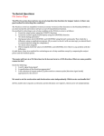
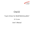
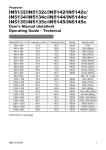
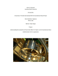
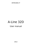
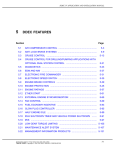
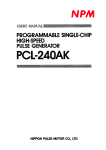
I ns t r uc t ion doc ument s
Pulse Control LSIs
Basic Description for PCL Series
Nippon Pulse Motor Co., Ltd.
Table of contents
I. Outline ・・・・・・・・・・・・・・・・・・・・・・・・・・・・・・・・・・・・・・・・・・・・・・・・・・・・・・・・・・・・・・・・ 1
1. PCL-240 family ・・・・・・・・・・・・・・・・・・・・・・・・・・・・・・・・・・・・・・・・・・・・・・・・・・・・・・・・・・・・・・ 1
2. PCL50oo series ・・・・・・・・・・・・・・・・・・・・・・・・・・・・・・・・・・・・・・・・・・・・・・・・・・・・・・・・・・・・・ 1
3. PCL61oo series / 60oo series ・・・・・・・・・・・・・・・・・・・・・・・・・・・・・・・・・・・・・・・・・・・・・・・・・ 1
II. Differences between the PCL series and PCD series ・・・・・・・・・・・・・・・・・・・・・・ 2
1. Which should be selected? ・・・・・・・・・・・・・・・・・・・・・・・・・・・・・・・・・・・・・・・・・・・・・・・・・・・ 2
Comparison of the basic functions
in the PCD45oo, PCL61oo, and PCL60oo series ・・・・・・・・・・・・・・・・・・・・・・・・・・・・・・ 2
2. PCL series features in Table 1 above. ・・・・・・・・・・・・・・・・・・・・・・・・・・・・・・・・・・・・・・・・・・ 2
III. Major additional facilities and functions of the PCL series ・・・・・・・・・・・・・・・・ 3
1. Encoder input
(A/B phase signal (90˚ phase difference signal) or bi-directional pulse signals)・・・ 3
2. Up/down counter ・・・・・・・・・・・・・・・・・・・・・・・・・・・・・・・・・・・・・・・・・・・・・・・・・・・・・・・・・・・・ 3
3. Servomotor interface ・・・・・・・・・・・・・・・・・・・・・・・・・・・・・・・・・・・・・・・・・・・・・・・・・・・・・・・・ 3
4. Pre-register (preliminary buffer for the next operation) ・・・・・・・・・・・・・・・・・・・・・・・・・・ 4
5. Rampdown point auto setting function ・・・・・・・・・・・・・・・・・・・・・・・・・・・・・・・・・・・・・・・・ 5
6. S-curve range setting ・・・・・・・・・・・・・・・・・・・・・・・・・・・・・・・・・・・・・・・・・・・・・・・・・・・・・・・・ 7
7. Operating speed correction function (FH correction function) ・・・・・・・・・・・・・・・・・・・・ 8
8. Various zero return methods ・・・・・・・・・・・・・・・・・・・・・・・・・・・・・・・・・・・・・・・・・・・・・・・・・・ 8
9. Comparator ・・・・・・・・・・・・・・・・・・・・・・・・・・・・・・・・・・・・・・・・・・・・・・・・・・・・・・・・・・・・・・・・・ 10
10. Pulsar input ・・・・・・・・・・・・・・・・・・・・・・・・・・・・・・・・・・・・・・・・・・・・・・・・・・・・・・・・・・・・・・・・・ 13
11. Stepper motor out-of-step detection function ・・・・・・・・・・・・・・・・・・・・・・・・・・・・・・・・・・・ 14
Instructions for the PCL60oo series
Outline・・・・・・・・・・・・・・・・・・・・・・・・・・・・・・・・・・・・・・・・・・・・・・・・・・・・・・・・・・・・・・・ 16
Features ・・・・・・・・・・・・・・・・・・・・・・・・・・・・・・・・・・・・・・・・・・・・・・・・・・・・・・・・・・・・・ 16
POINT 1. Interpolation operation ・・・・・・・・・・・・・・・・・・・・・・・・・・・・・・・・・・・・・・・ 16
What is linear interpolation? ・・・・・・・・・・・・・・・・・・・・・・・・・・・・・・・・・・・・・・・・・・・・・・・・・・・・ 16
What is arc interpolation? ・・・・・・・・・・・・・・・・・・・・・・・・・・・・・・・・・・・・・・・・・・・・・・・・・・・・・・ 16
What is synthesized constant speed control? ・・・・・・・・・・・・・・・・・・・・・・・・・・・・・・・・・・・・ 17
POINT 2. Continuous operation using the pre-registers ・・・・・・・・・・・・・・・・・・ 17
What is a pre-register? ・・・・・・・・・・・・・・・・・・・・・・・・・・・・・・・・・・・・・・・・・・・・・・・・・・・・・・・・・・ 17
POINT 3. Various acceleration/deceleration patterns ・・・・・・・・・・・・・・・・・・・・・ 18
POINT 4. Target position and speed override during operation ・・・・・・・・・・・・ 18
[Target position override] ・・・・・・・・・・・・・・・・・・・・・・・・・・・・・・・・・・・・・・・・・・・・・・・・・・・18
[Operation speed override] ・・・・・・・・・・・・・・・・・・・・・・・・・・・・・・・・・・・・・・・・・・・・・・・・・・19
POINT 5. Smooth the speed curve by using the FH correction function ・・・・ 19
What is the FH correction function? ・・・・・・・・・・・・・・・・・・・・・・・・・・・・・・・・・・・・・・・・・・・・・ 19
POINT 6. A variety of counters and comparators are built in ・・・・・・・・・・・・・・ 19
POINT 7. Other useful functions ・・・・・・・・・・・・・・・・・・・・・・・・・・・・・・・・・・・・・・・・ 21
■ Manual operation input ・・・・・・・・・・・・・・・・・・・・・・・・・・・・・・・・・・・・・・・・・・・・・・・・・・・・・・・ 21
■ Synchronous start control ・・・・・・・・・・・・・・・・・・・・・・・・・・・・・・・・・・・・・・・・・・・・・・・・・・・・ 21
■ CPU-I/F ・・・・・・・・・・・・・・・・・・・・・・・・・・・・・・・・・・・・・・・・・・・・・・・・・・・・・・・・・・・・・・・・・・・・・ 21
■ Idling pulse outputs・・・・・・・・・・・・・・・・・・・・・・・・・・・・・・・・・・・・・・・・・・・・・・・・・・・・・・・・・・ 21
■ Backlash correction / slip correction ・・・・・・・・・・・・・・・・・・・・・・・・・・・・・・・・・・・・・・・・・・ 21
■ Vibration restriction function ・・・・・・・・・・・・・・・・・・・・・・・・・・・・・・・・・・・・・・・・・・・・・・・・・ 21
■ Simultaneous start / simultaneous stop ・・・・・・・・・・・・・・・・・・・・・・・・・・・・・・・・・・・・・・・・ 21
■ Mechanical input signals ・・・・・・・・・・・・・・・・・・・・・・・・・・・・・・・・・・・・・・・・・・・・・・・・・・・・・ 22
■ Servomotor I/F ・・・・・・・・・・・・・・・・・・・・・・・・・・・・・・・・・・・・・・・・・・・・・・・・・・・・・・・・・・・・・・ 22
■ Output pulse specification ・・・・・・・・・・・・・・・・・・・・・・・・・・・・・・・・・・・・・・・・・・・・・・・・・・・・ 22
■ Emergency stop signal input ・・・・・・・・・・・・・・・・・・・・・・・・・・・・・・・・・・・・・・・・・・・・・・・・・ 22
■ Interrupt signal output ・・・・・・・・・・・・・・・・・・・・・・・・・・・・・・・・・・・・・・・・・・・・・・・・・・・・・・・ 22
POINT 8. A variety of operation modes ・・・・・・・・・・・・・・・・・・・・・・・・・・・・・・・・・・ 22
Basic description of PCL series
Basic Description for PCL Series
This document outlines the major functions of the PCL series pulse control LSIs, which are not part of the PCD
series
I. Outline
The PCD/PCL series pulse control LSIs manufactured by NPM now have a varied lineup. These products (17
models) can be divided into the following three groups, according to their command functions and registers.
・ PCL-240 family
PCD4500/4511/4521/4541
PCL-240AK/240MK/240AS/240MS
・ PCL50oo family (PCL50oo series)
PCL3013/5014
PCL5022/5023
・ PCL60oo family (PCL61oo series/60oo series)
PCL6113/6123/6143
PCL6025/6045B
1. PCL-240 family
In this family, each command is allocated a specific bit.
Basically, this is a simple family that has only four modes: start mode, control mode, register select mode, and
an output mode (8 bits are used for each mode). Since the PCL-240 series has a larger number of functions
than the PCD series, some commands for additional functions are accessed through registers.
2. PCL50oo series
The PCL55oo series has many more functions than the PCL-240 family, with lots of commands and registers.
The method for writing and reading this series is different from the PCL-240 family.
The PCL5022/5023 are LSIs for controlling two axes. The specifications for these LSIs when working on one
axis are not as broad as the PCL5014, which can be used for linear interpolation. (For details about linear
interpolation, see the user's manual for each model, or see page 17 in this document.)
3. PCL61oo series / 60oo series
The PCL60oo series has still more functions than the PCL50oo series, such as lots of counters, comparators,
and an arc interpolation function (see page 16). The bits for commands, registers, and status conditions have
been named for easy reference. This series contains the best models we offer.
PCL61oo series has fewer functions than the PCL60oo series, and they cost much less as well. Even though
the functions are limited, the basic high level functions are still present, such as servomotor control and linear
interpolation. The power supply requirement is just 3.3 V. They offer the highest output frequency offered by
the NPM pulse control LSIs, and they can control high-resolution linear motors.
•
When our models are classified by compatibility with software programs, there are 6 types, as shown
below:
(1) PCD4500/4511/4521/4541
(2) PCL-240AK/240MK/240AS/240MS
(3) PCL3013/5014
(4) PCL5022/5023
(5) PCL6113/6123/6143
(6) PCL6025/6045B
-1-
Basic description of PCL series
II. Differences between the PCL series and PCD series
1. Which should be selected?
Except for the excitation sequence output for a 4-pole (2-pole) stepper motor, there are no functions found in
the PCD series which are not found in the PCL series,
The PCD series have the minimum required functions for controlling stepper motors. In addition to these
functions, the PCL series can handle servomotors and are equipped with the various interfaces, encoder
inputs, and up/down counters that are needed to control servomotors. The registers related to speed patterns
have more bits to handle the high speeds of servomotors.
Each model also has other functions. However, to make the selection simple, if you want to control a closed
loop system using position detection equipment such as encoders, you should first consider using the PCL
series. If you want to control an open loop system using stepper motors, you should first consider using the
PCD series.
Table 1 sums up the basic performance offerings of the PCD series, PCL61oo series, and PCL60oo series.
Comparison of the basic functions in the PCD45oo, PCL61oo, and PCL60oo series
Model
Function
Number of axes controlled
Standard reference clock
frequency
Maximum pulse output
frequency
Number of registers for
specifying speed
Number of speed step settings
Speed multiplication range
Acceleration rate range
Deceleration rate range
Positioning pulse range
(countdown counter)
CPU interface
Rampdown point range
PCD4511/4521/4541
PCL6113/6123/6143
PCL6025/6045B
1/2/4
1/2/4
2/4
4.9152 MHz
19.6608 MHz (Max. 30 MHz)
19.6608 MHz (Max. 20 MHz)
2.4 Mpps
9.8 Mpps (Max. 15 MHz)
6.5 Mpps
2 (FL, FH)
2 (FL, FH)
3 (FL、FH、FA (for correction))
8,191 (13 bits)
16,383 (14 bits)
65,535 (16 bits)
1x to 300x
0.3x to 600x
0.1x to 100x
2 to 1,023 (10 bits)
(Used for both
acceleration/deceleration)
1 to 16,383 (14 bits)
1 to 65,535 (16 bits)
1 to 16,383 (14 bits)
1 to 65,535 (16 bits)
0 to 16,777,215 (24 bits)
-134,217,728 to +134,217,727
(28 bits)
-134,217,728 to +134,217,727
(28 bits)
8-bit bus
16-bit bus
16-bit bus
1 to 65,535 (16 bits)
1 to 16,777,215 (24 bits)
1 to 16,777,215 (24 bits)
<Table 1>
2. PCL series features in Table 1 above.
(1) The is a large number of speed steps.
=> Can output high frequency pulses with low speed multiplication.
=> Finer tuning of the speed setting is possible.
=> When the speed setting registers (FH or FL speeds) are set to the same values as in the PCD, the speed
multiplication rate can be set between 1/2 to 1/8.
(2) The acceleration and deceleration rates can be set independently.
=> For example, a short acceleration with a long deceleration is easily set. (Except for the PCL3013.)
(3) The setting range of the acceleration, deceleration rates, and the rampdown point is larger.
=> In the PCD series, these setting ranges are rather small, which places some restrictions on the
acceleration speed and the speed setting. In the PCL series, there is almost no restriction when setting
the maximum speed.
As shown above, the PCL series has almost no restriction on its operation, compared with
the PCD series.
-2-
Basic description of PCL series
III. Major additional facilities and functions of the PCL series
Though we cannot describe everything in detail here, this section will introduce the remarkable functions of the
PCL that are not found on the PCD series. (For an outline of all the functions, see the function description list.)
The symbols next to the additional functions or capabilities have the following meaning:
240
-> PCL-240 series function (except for the PCD series)
50oo -> PCL50oo series function
61oo -> PCL6100 series function
60oo -> PCL60oo series function
1. Encoder input (A/B phase signal (90˚ phase difference signal) or bi-directional pulse signals)
240 50oo 61oo 60oo
Mainly used to input signals from an encoder mounted on a servomotor. In some applications, an encoder is
mounted on a stepper motor to control the current position.
Encoder signals are input on the EA/EB terminals on the PCL50oo/61oo/60oo series.
The input signal type can be either an A/B phase signal (90˚ phase difference signals) or a bi-directional pulse
(positive and negative direction pulses). If A/B phase signals are selected, they can be multiplied by 2x or 4x.
Normally rotation type encoders are mounted at the back of the servomotor. Recently, however, linear type
encoders are being installed on linear motion stages that use linear motors.
An EZ encoder input terminal is available (except on the PCL-240AK) for inputting the Z-phase signal, that is
output once per rotation of the encoder. This is usually used, together with the ORG signal, to perform a
precision zero return positioning operation.
2. Up/down counter 240 50oo 61oo 60oo
The PCD series only have a down counter. However, the PCL series have an up/down counter as well as a
down counter. The up/down counter counts up while the motor is rotating in a positive direction and it counts
down while the motor is rotating in a negative direction.
This counter is mainly used to count A/B phase signals from the encoder.
Since the counter is counting signals from the encoder, you can know the exact current position at the moment
you read this counter.
This counter also can be used in the following way:
- Set it to not count when pulse signals are input, such as A/B phase signals.
- In addition to A/B phase signals, bi-directional pulse signals, which use so called positive and negative
direction pulses, can also be counted.
- In addition to external signals, such as A/B phase signals and bi-directional pulses, the counter can also
count pulses output by the PCL itself.
3. Servomotor interface 240 50oo 61oo 60oo
These LSIs have INP, ERC, and ALM terminals for making connections to a servo driver. For details about the
roles and functions of each signal, see the "Basics of servo motor control" and the " Function description list"
pamphlets.
-3-
Basic description of PCL series
4. Pre-register (preliminary buffer for the next operation) 50oo (Except PCL5022/5023) 61oo 60oo
The term pre-register refers to a register used to prepare for operation.
Simply put, this is just like a waiting room where the data for the next speed pattern is stored.
As you can see in <Table 2> below, the pre-registers are provided primarily for registers that determine speed
patterns.
Registers that have pre-registers
Register details
PCL3013/5014
Register name
PCL6113/6123/6143
PCL6025/6045B
R0
RMV
RMV
Feed amount (preset amount or target
position)
FL speed
R1
RFL
RFL
FH speed
R2
RFH
RFH
Acceleration rate
R3
RUR
RUR
Deceleration rate
R15
RDR
RDR
Speed multiplication rate
R4
RMG
RMG
Rampdown point
R5
RDP
RDP
Operation mode buffer
RMD
RMD
-
RIP
RIP
R16
(shared for both
acceleration /
deceleration)
RUS
RUS
RDS
RDS
Operation mode
Center position during arc interpolation, or
main axis feed amount during linear
interpolation
S-curve range during S-curve acceleration
S-curve range during S-curve deceleration
With preliminary buffer
Start command
<Table 2>
On the models that do not have pre-registers (PCD series, PCL-240 series, and PCL5022/5023), if you want to
use next different operating pattern after completing one operation, first the LSI confirms the end of the
previous operation using the INT signal or a status register. After confirming this, you have to write the data for
the next operation (preset amount, FL/FH speed, acceleration/deceleration rate, multiplication etc.) from a
CPU. If the register value is the same as in the previous operation, you only write the preset amount and any
other values you want to change. The time required to confirm the end of previous operation and write the data
for the next operation is only a few µs. However, this interval is simply waiting time before the ultimate
operation begins.
With pre-registers, you can write the data for the next operation during the current operation, so that the next
data are available as soon as they can be used. Then, the LSI can start the next operation immediately,
without the waiting time described above.
The operating pattern is a chain of multiple patterns, as shown in Figure 2.
- Without pre-registers
f
(3)
(1)
(2)
t
During this interval, the LSI confirms that operation (1) has stopped and writes the register
values and commands for operation (2). Therefore, there is a period when everything stops,
even though it is very short. (The same is true for the time between operations (2) and (3), etc.)
<Figure 1>
-4-
Basic description of PCL series
- With pre-registers
f
(3)
(1)
(2)
t
Using pre-registers, the LSI can prepare the data for the next operation during the current
operation, so that no time is lost between operations.
<Figure 2>
f
In another application, drawing a freestyle curve
(a sequence of short line segments) changes in
the speed are possible, as shown in Figure 3.
f4
f3
f2
f1
fL
P1
P2 P3
P4
P5
t
<Figure 3>
In order to start the next operation by eliminating the waiting time, you have to write the data to each of
pre-registers for the speed pattern settings, as well as the next operation’s start command.
The actual procedure is as follows. To operate a motor with the pattern shown in Figure 2, do the following:
a) First, write the values for operation (1) in each pre-register.
b) Write a start command. The moment the start command is written, all of the values are copied into the
appropriate operation registers and the LSI starts operation.
c) After starting operation, the values for operation (2) must be written to the LSI. However, the pre-registers
still contain the values that were written in step a) above, so you only need to overwrite those values that
are different from operation (1). (However, the feed amount [preset amount or target position] still needs to
be written again, even if the value is the same as in the previous operation, because the counter is reset to
zero when the current operation is complete.)
d) During the execution of operation (1), write the next operation start command.
e) After operation (2) has started, repeats step c) and d) for subsequent operations.
5. Rampdown point auto setting function 240 50oo 61oo 60oo
For positioning operations (preset operations) with the PCD series, we have to set a rampdown point
(deceleration start point) for acceleration/deceleration operations, in order to tell the LSI the number of residual
pulses at which to start deceleration.
All models in the PCL series have a rampdown point auto setting function. Using this function, you don’t need
to write the rampdown point setting register for each operation.
There are two ways to think about using the PCL series rampdown point auto setting function.
-5-
Basic description of PCL series
(1) Count Method (PCL-240AK/240MK,3013,5022,6113/6123/6143)
This system counts the number of pulses used for acceleration (the number of pulses between FL and FH
speed). When the number of residual pulses is equal to this amount, the LSI starts the deceleration.
Count method
When the number of pulses used for the
acceleration is equal to the number of
residual pulses, the LSI starts the
deceleration.
f
FH
FL
t
Counts the number of pulses
needed for acceleration,
Then, sets the same number of
pulses as the rampdown point.
<Figure 4>
This method requires the (acceleration time) = (deceleration time). If you want to change the deceleration time
(if you want to have an asymmetrical pattern, you have to disable the auto setting of the rampdown start point.
In this case you will have to write a value into the rampdown point setting register, just like with the PCD series.
(This is generally referred to manual rampdown point setting.)
(2) Calculation Method (PCL-240AS/240MS,5014,5023,6025/6045B)
In contrast with the Count Method (1), this method always calculates the number of pulses required to
deceleration rate and stop. The calculated result is used as the rampdown point.
The advantage of this method is that the deceleration time can be different from the acceleration time.
(Asymmetrical speed patterns are possible) => This was designed for users who want the deceleration time
to be shorter than the acceleration time that would be set using the rampdown point auto setting function.
Calculation
method
Calculates the number of pulses needed to reach FL speed from the current FH
speed, using the current deceleration rate and use this value as the rampdown point.
f
Start decelerating using the deceleration rate that is set.
FH
FL
<Figure 5>
t
-6-
Basic description of PCL series
6. S-curve range setting
240 (except for the PCL-240AK/240MK), 50oo (except for the PCL3013/5022),
61oo 60oo
With a normal S-curve, the center point of the
S-curve (point A in Figure 6) has the largest
acceleration rate (a steep slope).
This means that the motor must accelerate
rapidly at this point. So, the stepper motor may
get out-of-step.
f
FH
Point A (A large rate of
acceleration. By drawing the
tangent, you can see how
steep the slope is.)
FL
<Figure 6>
t
f
PCL series models that have S-curve
acceleration / deceleration can make this
intermediate part a straight line (except for PCD
series and the PCL3013). By providing a straight
line here, the acceleration rate will be smaller
(the slope will be less steep) and an out-of-step
condition can be prevented.
By setting the S-curve range, the length of the
straight line can be set freely.
S-curve range
FH
By insetting a straight line,
the acceleration rate will
be smaller (the slope will
be less steep).
FL
<Figure 7>
t
-7-
Basic description of PCL series
7. Operating speed correction function (FH correction function)
240(except PCL-240AK/240MK)
50oo (except for the PCL3013/5022) 61oo 60oo
f
In order to eliminate the sharp peak of the
triangle shape in Figure 8 in the PCD series, you
must manually calculate the peak speed FH'.
Then, you can set a top speed that is a little
smaller than the FH' value.
FH
FH’
FL
<Figure 8>
t
f
Models that offer S-curve acceleration /
deceleration (except for the PCD series and the
PCL3013), have an FH correction function that
can automatically set this FH' value internally. By
enabling this function, the LSI can create an
S-curve that uses FH' speed as the top speed,
so that the peak of the shape will be smooth.
FH
FH’
FL
<Figure 9>
t
8. Various zero return methods
In the PCD series, there is no other way to decelerate and perform a zero return than to turn ON the SD
sensor to start deceleration and then stop when the ORG sensor turns ON. In the PCL series however, you
can select various methods to perform a zero return, such as using an encoder Z-phase signal and you do not
have to use the SD sensor.
This section discusses typical zero return methods.
(1) Decelerate on receiving the SD signal and stop on the ORG signal.
f
Start deceleration when
SD goes ON
This is the normal zero return method, the same
as the PCD series. After starting with an
acceleration/deceleration pattern, when the SD
sensor goes ON the motor starts to decelerate.
When the ORG sensor goes ON, the motor
stops.
FH
Sop when ORG
goes ON
FL
<Figure 10>
240 50oo 61oo 60oo
t
-8-
Basic description of PCL series
(2) Turn ON the SD signal and when the ORG signal goes ON the LSI starts counting the EZ pulses. When the
number of EZ pulses reaches the preset value, stop the motor. 240 50oo 61oo 60oo
f
Start deceleration when
SD goes ON
Count the specified
number of EZ pulses
and then stop
FH
The zero return method described in (1) may
have a deviation of a few pulses from the actual
zero point. This is method allows returning to the
zero position more accurately, using the Z-phase
signal from an encoder.
The number of EZ pulses counted can be set
between 1 and 16.
ORG = ON
FL
t
<Figure 11>
(3) When the ORG signal goes ON, the motor starts to decelerate and begins counting EZ pulses. When the
number of EZ pulses counted reaches the preset value, the motor stops. 50oo 61oo 60oo
f
Start to decelerate when
ORG goes ON
Stop after counting
the preset number of
EZ pulses
FH
This method uses the ORG sensor in place of
the SD sensor. You can use it if you want to
avoid using the SD sensor.
FL
<Figure 12>
t
(4) When the R0 pre-register set value is reached, the motor stops. 50oo
ORG sensor
This mode is basically the same as described in
(1) to (3) above. However, the motor will stop
when the number of pulses is equal to the R0
pre-register value, and does not require
returning to the zero position.
One example of its use is to zero-return the
motor using rotation, if the ORG sensor is
disconnected or broken, the ORG signal cannot
be input so the motor can never stop.
Then, by setting a rather larger number of pulses
in R0, the motor can be stopped when it reaches
that number of pulses. If the motor is stopped in
this way, arrange to output an error, and you will
know that there is a problem on or around the
ORG sensor.
Put a large amount in R0 as a preset value, if the
ORG sensor is broken, the motor can be stopped
when the pulses equal this preset amount.
<Figure 13>
(5) Moving away from zero position 50oo(except PCL5022/5023) 60oo
This method is used to stop the motor after the ORG signal goes ON and then OFF. This is used in cases
where the first ORG ON does not really occur at the zero position.
-9-
Basic description of PCL series
(6) Zero position search operation 50oo(except PCL5022/5023) 60oo
In this zero search, the motor rotates between the -EL sensor and +EL sensor, back and forth, and finally finds
the zero position from the specified direction. Internally, this is configured by automatically switching between
zero return operations and zero leaving operations.
(7) Other zero return operations 60oo
Other zero return operations are possible with the PCL6025/6045B: a) return to a memorized ORG signal ON
position, b) the motor decelerates, stops and then reverses when the EL signal goes ON. When the specified
number of EZ pulses is counted, the motor stops.
For the details about methods (5), (6), and (7), see the User's Manual for these operation modes.
9. Comparator
f
50oo(Except PCL5022/5023) 61oo 60oo
The comparator refers to a comparison circuit.
Compare the preset value (i.e. the comparator
data) with an internal counter value. When the
comparison condition is met, the LSI will output
a signal, or the PCL can take further action.
In simple terms, it lets you know when the
machine has passed a position with a signal,
which can be used to have the machine do
something else.
The details of the comparator function vary with
each model.
The PCL60oo series can store five comparator
data. The internal action that occurs when a
condition is met can be selected from various
items. The PCL3013/5014 and PCL61oo series
can store two comparator data. However, the
PLC61oo series have a simplified version of this
function.
When the motor reaches a preset
position, a signal is output.
FH
FL
<Figure 14>
t
This section discusses examples of the comparator function in the PCL3013/5014.
We’ll refer to comparator 1 data as "CMPD1," Comparator 2 data are "CMPD2," the countdown counter value
is "DC," and the up/down counter value is "UDC."
(1) What kinds of conditions can be specified?
You decide which conditions will be used for the CMPD1 (or CMPD2) and DC (or UDC), and the signal to be
output. You can select from 13 types of conditions, including those shown below.
a) When UDC is equal to CMPD1, output a signal. (CMPD1 = UDC)
b) When UDC is larger than CMPD1, output a signal. (CMPD2<UDC)
c) When DC is smaller than CMPD2, output a signal. (CMPD2>DC)
d) When UDC is larger than CMPD1, and is smaller than CMPD2, output a signal (CMPD1<UDC<CMPD2)
(2) What does it mean to put out a signal?
a) The CMP terminal goes ON (LOW) unconditionally when the comparator conditions are met.
b) An INT signal can be output. Set bit 12 in R8 (Environment register 3)
(3) What kinds of internal processing will the PCL do when the conditions are met?
The PCL3013/5014, in addition to turning ON the CMP terminal and outputting an INT signal, can do any of
the four things below.
a) Do nothing.
b) Immediately stop outputting pulses.
c) Continue the internal operation but don’t output pulses.
d) Change the FH speed or the acceleration/deceleration rate to the pre-register values.
=> Select one of the actions the above using bits 20 and 21 in R7 (Environment register 2).
-10-
Basic description of PCL series
* In the PCL61oo series, a comparison between inside the range and outside the range, as described above in
(1) a) and d), is not possible (It must be handled by a CPU.). Also the PCL61oo series cannot execute internal
action (3) c) above. Therefore, when the conditions are met, only the CP1/CP2 terminals (CMP terminal on the
PCL5014) go ON, or an INT signal is output.
In the PCL60oo series, in addition to a), b), and c) above, they have lots of counters for comparisons and can
take various other actions. For details, see the respective User's manual.
(4) Example with a PCL3013/5014
a) Using only one comparator
200,000 pulse position (when the counter
value reaches 20,001, output an INT signal
and accelerate toward a 7,000 pps speed at
an acceleration rate of 500)
★ During operation with a preset amount of 50,000,
when the up/down counter value exceeds
20,000, output an INT signal and start
accelerating the motor.
Set as follows:
- R0 pre-register (preset amount) = 50000
- R1 pre-register (FL speed) = 1000
- R2 pre-register (FH speed) = 5000
- R3 pre-register (acceleration rate) = 1000
- R4 pre-register (multiplication) = 299 (1x)
- R10 (comparator 1 data)=20000
- Set R8 (Environment register 3) bit 13 = 1
(output an INT signal when the comparator
conditions are met)
- Set R7 (Environment register 2) bits 16 to 19 =
00100 (comparator condition: R10 < counter)
- Set R7 (Environment register 2) bits 20 to 21 =
11 (fill R2 and R3 with the pre-register values)
f(pps)
7000
5000
1000
Preset amount
50,000
<Figure 15>
t(s)
- Set R7 (Environment register 2) bit 22 = 0 (comparison counter to use: up/down counter)
- Set the up/down counter to 0. (Control command 61h)
- Set the operation mode buffer, control mode buffer, and other register values and trigger a start
(high-speed start: 13h)
=> Accelerate from 1,000 pps to 5,000 pps.
- After starting, write 7,000 into the R2 pre-register and 500 into the R3 pre-register.
Then, when the up/down counter reaches 20,001 (the 20,001st pulse after starting), the motor will operate as
follows:
- The motor will accelerate from 5,000 pps to 7,000 pps with an acceleration slope of 500. (In other words,
the R2 and R3 pre-register values are copied into the registers.)
- The CMP signal goes LOW (ON).
- The INT signal goes LOW (ON).
-11-
Basic description of PCL series
b) Using two comparators
Out of range
-10000
Only possible to
operate in this range
0
Out of range
★ Make it possible to operate only within the range
of positions between –10,000 and +10,000. If
the machine tries to operate outside this range,
stop immediately and output an INT signal.
To do this, use the following settings:
- R10 (comparator 1 data) = -10,000
- R11 (comparator 2 data) = 10,000
- Set R8 (Environment register 3) bit 13 = 1
(output an INT signal when the comparator
conditions are met).
+10000
<Figure 16>
- Set R7 (Environment register 2) bits 16 to 19 = 1000
(comparator condition: R10 > counter, R11 < counter)
- Set R7 (Environment register 2) bits 20 to 21 = 01 (immediately stop outputting pulses)
- Set R7 (Environment register 2) bit 22 = 0 (comparison counter to use: Up/down counter)
With these settings, if the value of the up/down counter becomes smaller than -10,001 or larger than +10,001,
the motor will stop immediately and the CMP and INT signals will go LOW (ON).
(5) Software limit 60oo
The software limit is different from the hardware end limits, such as the ±EL sensors. It is used to set both
ends of a range using two comparators. Basically, the LSI operates with the range of the data from two
comparators, allowing them to function as software end limits.
When the comparator conditions are met (the machine has moved outside the software limit range), the motor
stops immediately and cannot rotate any more in the same direction. However, the motor can be rotated in the
opposite direction.
The software limit function is found in the PCL6025/6045B, but not in the PCL50oo or PCL61oo series.
Example (4) b), in Section 9 of Chapter III looks like a software limit function. When the comparator conditions
are met (outside the range), the motor stops immediately. However the motor cannot be moved any more, not
even in the opposite direction.
Therefore, in order to make it possible to move the motor with the PCL3013/5014, change bits 20 to 21
(selected action when the comparator conditions are met) in R7 from 01 to 00 (do nothing) (R7 is Environment
register 2). By setting it to do nothing, the motor can be rotated in the opposite direction. However, please note
that in this case, the motor can also be moved further in the direction it was going when it went past the limit.
-12-
Basic description of PCL series
10. Pulsar input
50oo 61oo 60oo
(1) What is a pulsar?
Generally, pulsars look like the one in Figure 17.
The rotating dial is equipped with an encoder,
and can be turned with the handle on the dial.
The dial is just like the dial on a safe. It clicks as
it turns. Turn it clockwise to move in the positive
direction.
The pulsar in the photo on the left has two rotary
switches. The left rotary switch is used to select
the axis to move (up to six axes can be
addressed separately). The right rotary switch is
used to select the units (how many pulses per
tick on the dial).
<Figure17>
Basically, most pulsars can output A/B phase
signals.
When an operator needs to adjust the position of
a workpiece on a stage, push buttons may be
used to adjust it in a positive or negative
direction. However, in order to make fine
adjustments to the position, the pulsar may be
more efficient.
<Figure 17>
Emergency stop button
Multiplier (number of pulses per tick on
the dial)
x1: One pulse per tick.
x10: 10 pulses per tick.
x100: 100 pulses per tick.
<Figure 18>
Select the axis to control
An bare encoder with a marked dial, as shown to the left,
can be purchased and installed on a control panel.
<Figure 19>
-13-
Basic description of PCL series
(2) Manual pulsar input on the PCL
This is a function used to receive encoder signals from some other encoder than the feedback encoder on the
back of the motor. Then, pulses can be output from the OUT and DIR terminals. A manual pulsar is not used to
output pulses like a start command. However, as you turn the dial, the motor will rotate and the up/down
counter can count the amount moved.
The PCL can read pulsar signals on both the PA and PB terminals.
The input signal type can be A/B phase signals (90˚ phase difference signals) or bi-directional pulses (positive
and negative direction pulses). When A/B phase signals are selected, you can set the multiplier to 1x, 2x, or
4x.
The PCL outputs pulses from the OUT and DIR terminals that are synchronized with the speed at which you
turn the dial. If a stepper motor is used, turning too fast may cause it to get out of step. Therefore, the PCL is
set so that it won’t output pulses at a high frequency, with the FH speed being used as the upper limit.
11. Stepper motor out-of-step detection function
Encoder
(200 ppr)
50oo 60oo
2-pole HB type stepper motor
(2-2 phase excitation, 200 ppr)
This function detects out-of-step of stepper
motors.
To use this function, install an encoder with the
same resolution as the stepper motor on the
same axis as the stepper motor, as shown in
Figure 20.
The PCL compares the number of pulses output
by itself with the pulses returned from the
encoder. If the difference exceeds a preset value,
the PCL determines that an out-of-step condition
has occurred and its takes a specified action.
The action taken when an out-of-step condition
is detected varies with each model.
<Figure 20>
(1) PCL50oo series
This series stops the motor immediately and
outputs an INT signal. (The PCL50oo series has
a deflection counter for detecting an out-of-step
motor. This counter manages the deflection
amount.)
For example, if the maximum deflection detection amount is set to 5, when the difference between the number
of output pulses and returned pulses is 5 or less, the PCL considers that OK. If the difference is 6 or more, the
PCL declares that the motor is out-of-step and outputs an INT signal.
(2) PCL60oo series
This series detects an out-of-step condition using Comparator 3 and COUNTER3 (the deflection counter).
Therefore, the action taken when an out-of-step is detected can be selected from the actions available when
the comparator conditions are met. (Same as in section 9 (3) in Chapter III.)
The PCL50oo series has ERA/ERB terminals, exclusively for connecting an out-of-step detection encoder.
With the PCL60oo series, the EA/EB terminals are shared for use with an out-of-step detection encoder. Just
like with a pulsar input, you can choose the pulse style: A/B phase signals (90 phase difference signal) or
bi-directional pulse signals (positive and negative direction pulses). When A/B phase signals are selected, you
can set the multiplier to 1x, 2x, or 4x.
* The PCL61oo series does not have an out-of-step detection function.
What the PCL61oo series can do is as follows:
a) Count output pulses using COUNTER1.
b) Count encoder signals (EA/EB input) using COUNTER2.
<To check during operation>
c-1) During operation, latch COUNTER1 and COUNTER2 using the latch command, and then check the
difference between them using a CPU. (If you want to perform this check by using an interrupt, create a
program that will make this comparison at a specified interval using the comparator.)
<To check while stopped>
c-2) Check the COUNTER1 and COUNTER 2 values while stopped to determine if there was an abnormal
difference in the counts.
-14-
Basic description of PCL series
So, the PCL60oo series needs you to write a program to compare the two values and determine if an
out-of-step condition has occurred.
So far, this document has been describing the major functions, focused mainly on the PCL50oo and
PCL61oo series.
Starting on the next page we would like to describe enhanced control functions such as interpolation
controls and a target position override function, using the PCL6025/6045B for our example (the top of
the line NPM pulse control models).
The following descriptions are taken from instruction manual for the PCL6025/6045B. The
PCL6025/6045B have all the functions that are described in this document. However, the PCL5022/5023,
and PCL61oo series also have some of the functions, such as linear interpolation and target position
override. Please refer to the "List of functions."
-15-
Basic description of PCL series
Instructions for the PCL60oo series
Outline
After receiving control commands from a CPU bus interface, the PCL6025/6045B controls stepper motors and
servomotors that are driven by pulse train inputs.
One of these LSI chips provides independent control (variable continuous operation, zero return operation, and
positioning operation using constant speed, linear acceleration/deceleration, S-curve
acceleration/deceleration) of two or 4 axes, linear interpolation between two to four axes and arc interpolation
between two axes.
Features
POINT 1. Interpolation operation
The PCL6025/6045B offers the following interpolation operations:
◆ Linear interpolation 1: One chip in this series can provide linear interpolation of any two to four axes.
(Two axes only with the 6025)
◆ Linear interpolation 2: Multiple chips in these series can provide linear interpolation of five or more
axes.
◆ Arc interpolation:
Arc interpolation between any two axes. (Between the X and Y axes for the
6025)
The interpolation operation can be executed up to the maximum pulse frequency (approx. 6.5 Mpps with a
reference clock of 19.6608 MHz) in both linear and arc interpolations.
******** What is linear interpolation?****************
To execute a linear interpolation, specify the end
point coordinates and the desired linear
interpolation operation. Specify the end point as
an incremental number of pulses from the current
position on each axis.
The PCL automatically identifies the axis with the
larger feed amount as main axis, and the other
axis is the slave axis. The main axis is supplied
with pulses and the slave axis is supplied with a
reduced number of pulses based on the
interpolation calculations.
Figure 1 shows a two-axis linear interpolation
with end point coordinates of (10, 4) using the X
and Y axes.
******** What is arc interpolation?*******************
To execute an arc interpolation, take the current
position as the starting point (coordinate position
0, 0) and specify the center and end point
coordinates of an arc. Then select either a CW or
CCW arc interpolation operation. Enter the center
coordinate and end point coordinates as
incremental values from the current position
(starting point).
The CW arc interpolation draws an arc from the
current coordinates to the end point coordinates
in a clockwise direction, using the center
coordinates as the center of the arc. The CCW
arc interpolation draws an arc in a
counterclockwise direction.
Figure 2 is an example of drawing an arc with the
X and Y axes in a CW arc interpolation operation.
Y (slave axis)
End point
coordinates
(10, 4)
4
3
2
1
Current
coordinate
0
(0, 0)
0
X axis
output
pulses
Y axis
output
pulses
1
2
3
4
5
6
7
8
9
10
X (main axis)
Pulse out
[Two-axis linear interpolation]
Figure 1
Y (slave axis)
End point
coordinates
(10, 10)
10
9
8
7
6
5
4
3
2
1
Start point
0
(0, 0)
0
X axis
output
pulses
1
2
3
4
5
6
7
8
9
11
X axis
12
Center coordinate (10, 0)
Y axis
output
pulses
Pulse ON
[CW arc interpolation: 90o arc]
-16-
10
Figure 2
Basic description of PCL series
Y
*** What is synthesized constant speed control? *****
Figure 3 shows the locus of a two-axis
interpolation operation.
Following the basic pulses sent to the main axis,
pulses are output to each axis. In the figure,
when both the X and Y axis pulses are output,
they have to feed longer distance (x √ 2)
compared with single axis feeding.
Therefore, with the synthesized constant speed
control during simultaneous operation of two
axes, the PCL will increase the speed x 1/√ 2
X
X axis output
pulses
Y axis output
pulses
t
(multiplying the pulse output time x √ 2). When
you want to operate three axes simultaneously,
the speed of each axis is multiplied x 1/√ 3.
tx 2
[An example of two axes interpolation]
Figure 3
POINT 2. Continuous operation using the pre-registers
********What is a pre-register? ******************************
The pre-registers are registers in which you can write the data (feed amount, initial speed, operation speed,
acceleration/deceleration rate, speed multiplication rate, rampdown point, operation mode, arc interpolation
center, and S-curve range during acceleration/deceleration) needed for the next operation, and each
subsequent operation.
The pre-registers have the two-step design shown in Figure 4. They operate as a FIFO.
Change
Setting
2nd
pre-register
1st
pre-register
Operation
control circuit
Register
Figure 4
Normally, operation data is written to the 2nd
pre-register, and when you want to change the
current operation, such as changing the speed,
you write new data directly to the registers.
When the current operation is complete, the PCL
automatically starts the next operation using the
data in the pre-register. This method of operation
eliminates any delay that would interrupt the
process and reduces CPU processing time to
provide smooth, continuous operation.
Although the pre-register has of two stages,
when you are allowed to write to the 2nd
pre-register by the current operation completing,
the PCL can output an interrupt signal to a CPU,
so that the PCL can operate continuously, as
shown in Figure 5.
1) CW arc interpolation (180o)
3) 5) CW arc interpolation (90o)
2) 4) 6) Linear interpolation
Y axis
2)
3)
4)
1)
5)
6)
X axis
[Continuous interpolation operation of arcs and lines]
Figure 5
-17-
Basic description of PCL series
POINT 3. Various acceleration/deceleration patterns
Each speed pattern can specify the following
elements independently:
- Initial speed
- Operation speed
- Acceleration speed characteristics
(acceleration rate, acceleration S-curve
range)
- Deceleration characteristics
(deceleration rate, deceleration S-curve
range)
f
Operation
speed
Figure 6
[Speed pattern]
Acceleration rate
Deceleration rate
Deceleration
S-curve range
Acceleration
S-curve range
Positioning operation
feed amount
Initial speed
t
Ramp down point of positioning operation: Manual or automatically set
f
f
f
Therefore, the various acceleration/deceleration
patterns in Figure 7 can be used.
t
f
t
f
t
f
The rampdown point can be set automatically as
long as the (Deceleration time) (Acceleration
time x 2)
t
f
t
t
f
[Examples of
acceleartion /
deceleration
patterns]
t
Figure 7
t
POINT 4. Target position and speed override during operation
During operation, the target position and speed
can be changed freely (by overwriting them).
[Target position override]
[Target position override]
By overwriting the target position data during
operation, the target position can be overridden.
The PCL changes the target position with the
start position as the reference point.
The examples in Figure 8 are as follows:
Figure 8
f
◆ When the target position is changed to a point further
away than the preset target position during acceleration
or constant speed operation, the PCL will operate with
the current speed pattern and complete the positioning
using the new data.
◆ When target position is changed to a point further away
than the preset target position while decelerating, the
PCL will accelerate again from the current position to the
specified operation speed and then complete the
positioning using the new data.
◆ When the motor has already passed the new position, or
you change the target position so that it is closer than the
preset target position while decelerating, the motor will
decelerate and stop. Then it will reverse and complete
the positioning using the new data.
-18-
Change to far
away position
f
Change to far
away position
f
f
f
f
Change to already
passed position
Basic description of PCL series
[Operation speed override]
By changing the speed settings during operation, you can change the speed and the acceleration rate.
(1) When the operation speed is changed to a lower speed than the preset while accelerating, and if the new
speed < current speed, the motor will use S-curve deceleration to reach the new speed.
(2) (3) When the operation speed is changed after acceleration is complete, the motor will use S-curve
deceleration to reach the new speed.
(4) When a higher operation speed is written during acceleration, the motor will accelerate to the preset speed
without changing the S-curve pattern. Then it will accelerate again to the new speed.
(5) When a lower operation speed is written during acceleration, and if the new speed > speed when the change
was written, the motor will accelerate to the new speed without changing the S-curve characteristics.
Spee
Examples of speed pattern changes by overwriting the
speed during S-curve acceleration / deceleration
4)
2)
5)
3)
1)
Time
Figure 9
POINT 5. Smooth the speed curve by using the FH correction function
*** What is the FH correction function? ・・・***
pps
[FH correction function]
Figure 10
During a positioning operation, if the feed amount
is very small, this function automatically lowers
the maximum speed and avoids triangle driving.
This smoothes the speed curve.
Automatic correction of the maximum speed for small
feed amounts.
POINT 6. A variety of counters and comparators are built in
Beside a dedicated positioning counter, the PCL6025/6045B have four counter circuits per axis.
Counter 1 is exclusively for outputting pulses. The input for Counters 2 to 4 can be selected with a CPU.
All of the counters can latch and reset their counter values from a signal input, and respond to operating
conditions and commands from a CPU so that you can use them in a variety of applications.
-19-
sec
Basic description of PCL series
(○ : Can count, Blank: Can’t count)
Counter1
Counter 2
Counter 3
Command
position
Up/down
counter
28
Mechanical
position
Up/down
counter
28
○
Counter 4
Deflection
counter
16
General-purpo
se
Up/down
counter
28
○
○
○
Encoder (EA/EB) inputs
○
○
○
Pulsar (PA/PB) inputs
○
○
○
Counter name
Counter type
Bit length
Output pulses
Deflection
○
Reference clock cycles/2
The PCL6025/6045B have five built in circuits with 28-bit comparators (CMP1 to 5), and can select the
comparison data shown in the table below.
In addition, there are 9 methods for comparison and four responses to choose from when the conditions are
met.
By using the comparators and counters above, you can do the following:
◆ Interrupt output, output comparison results externally, use as an internal synchronous start.
◆ Immediate stop, or deceleration stop of the operation
◆ Automatic speed change during operation
◆ Software limit function
◆ Out-of-step detection for stepper motors
◆ Synchronous signal output
(○ : Can compare, Blank: Can’t compare)
Comparison data
CMP1
CMP2
CMP3
CMP4
CMP5
Counter 1
○
○
○
○
○
Counter 2
○
○
○
○
○
Counter 3
○
○
○
○
○
Counter 4
○
○
○
○
○
Positioning counter
○
Current speed
○
Pre-register
Major applications
None
None
Software limit function
Positive limit
Negative limit
None
None
Yes
Auto speed
change
[Example of the software limit function]
Negative limit position
Positive limit position
Normal operation range
Can’t move in further
the negative direction
Can move in the
positive direction
Operation after reaching the negative
limit position
Can move in the
negative direction
Can’t move
further in the
positive direction
Operation after reaching the positive
limit position
-20-
Basic description of PCL series
POINT 7. Other useful functions
■ Manual operation input
The manual operation input can be used to allow an operator to operate a motor with switches or a manual
pulsar, instead of through a CPU.
Using a manual pulsar or switch input, each axis can be operated independently.
First, write a start command for manual operation mode with a CPU. Then the PCL can output pulses in
response to switches or pulsar inputs.
■ Synchronous start control
A synchronous start can be executed in the following two conditions.
◆ Start when another axis stops
With this function, when one axis or multiple axes stop (for example when the X and U axes stops or when
the X, Y, and Z axes stop), this can be set as the condition for starting another axis.
◆ Start on an internal synchronous signal
There are nine types of timing for the internal synchronous signal (comparator conditions are met,
start/complete acceleration, start/complete deceleration). Select one of these.
■ CPU-I/F
You can select one of the following four types as a CPU hardware interface.
1) For a Z80 CPU
8-bit
2) For a 8086 CPU 16-bit
3) For an H8 CPU 16-bit
4) For a 68000 CPU 16-bit
■ Idling pulse outputs
When starting with acceleration/deceleration this function makes it possible to accelerate to the initial speed
after a few pulses of operation (idling pulses). By setting the initial speed higher with acceleration/deceleration
control, a stepper motor can be protected from encountering an out-of-step condition.
■ Backlash correction / slip correction
The backlash/slip correction outputs a number of correction pulses at correction speed just before starting a
command operation.
The backlash correction function is activated each time the feed direction is changed. The slip correction
function is activated just before a command operation, regardless of the operation direction.
■ Vibration restriction function
This function adds one pulse of reverse operation and one pulse of forward operation just before completing a
command operation, so as to limit vibration when stopping.
The output timing for adding the pulses can be set in the register.
■ Simultaneous start / simultaneous stop
Multiple axes controlled by one IC or multiple axes controlled by multiple ICs can be started simultaneously by
commands or external signals.
Also, this function can stop all the axes at the same time on a command, an external signal, or by an error stop
on any axis.
-21-
Basic description of PCL series
■ Mechanical input signals
The following four signals can be input for each axis:
1) +EL --- When this signal turns ON while operating in the positive direction, the motor stops immediately,
or decelerates and stops.
2) -EL --- When this signal turns ON while operating in the negative direction, the motor stops immediately,
or decelerates and stops.
3) SD --- Used as a deceleration signal or a deceleration stop signal by a software setting.
4) ORG --- Input signal for a zero return operation
The input logic for the +EL/-EL signals can be changed with hardware.
The input logic of the SD/ORG signals can be changed with software.
■ Servomotor I/F
The following interface can be provided for the following three signals on each axis.
1) INP --- Input a positioning complete signal that is output by a servomotor driver.
2) ERC --- Output deflection counter clear signal, sent to a servomotor driver.
3) ALM --- Input an alarm signal that is output by a servomotor driver.
When this input signal goes ON, the motor stops immediately, or decelerates and stops.
The input/output logic of the INP, ERC, and ALM signals can be changed with software.
The ERC signal is a pulse output and the pulse length can be selected.
■ Output pulse specification
Select either common pulse or two pulse mode. The output logic can be selected.
■ Emergency stop signal input
When this signal goes ON, all the axes stop immediately. While this signal is ON, no axis can be operated.
■ Interrupt signal output
An interrupt signal can be output by 17 types of errors and 19 types of events. The error interrupt causes are
always unconditionally output. However, the event causes can be set in the registers.
-22-
Basic description of PCL series
POINT 8. A variety of operation modes
Roughly speaking, the PCL series have 18 operation modes.
Command continuous
operation
Pulsar continuous
operation
Switch continuous
operation
Zero return operation
Zero position leave
operation
Limit positioning
operation
Starts by a start command, stops by a stop command.
After writing a start command, synchronizes pulsar input with output
pulses.
After writing a start command, outputs pulses controlled by a switch
input.
Feed to the zero position: 13 zero return sequences are available.
When the zero position sensor is ON, it moves the motor to a position
where the sensor signal goes OFF.
Moves to the end limit position or software limit position.
Limit leaving operation
When a motor is on an end limit position or software limit position, it
moves it to a position where the limit signal turns OFF.
Positioning operation
Zero position return
operation
One pulse operation
Set a target position and start a positioning operation.
Move to a command position or towards a position until the current
position counter becomes 0.
Output just one pulse.
Timer operation
The IC performs a positioning operation internally. However, it does not
output pulses. Used as a process timer.
Pulse synchronized
positioning
Switch input positioning
Linear interpolation 1
operation
Linear interpolation 2
operation
Continuous linear
interpolation operation
Continuous linear
interpolation 2
operation
Arc interpolation
operation
Positioning operation synchronized with the pulsar input.
Output a preset number of pulses each time a switch signal is input.
Linear interpolation of any two to four axes.
Linear interpolation of five axes or more using multiple ICs.
Operation using linear interpolation 1. But the operation continues until
a stop command is input.
Operation using linear interpolation 2. But the operation continues until
a stop command is input.
Arc interpolation with any two axes. Can draw a perfect right circle.
In the discussion above, we have only been outlining the features and functions of the PCL series.
For items not described in this document or details of the individual functions, see the user's manual
for each model.
We hope this document will be helpful in your selection of a PCL model.
-23-
Basic description of PCL series
Nippon Pulse Motor Co., Ltd.
Asia/Europe: Nippon Pulse Motor Co., Ltd.
2-16-13 Hongo, Bunkyo-ku, Tokyo 113-0033, Japan
TEL: 81-3-3813-8841
FAX: 81-3-3813-7049
Web: http//www.pulsemotor.com
E-mail: [email protected]
North/South America: Nippon Pulse America, Inc.
1073 East Main Street, Radford, VA 24141, U.S.A.
TEL: 1-540-633-1677
Web: http//www.nipponplse.com
FAX: 1-540-633-7049
E-mail: [email protected]