1
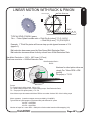
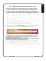
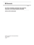
BLADERUNNER AIO RIGHT SIDE VIEW
INPUTS FOR UBOB III AND EXPANSION OPTIONS
CLOSE UP VIEW UBOB MODULE
RIGHT SIDE
CandCNC
Page
E
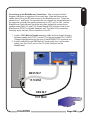
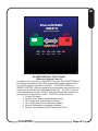
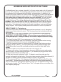
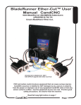
Connecting up the BladeRunner Control box. Take a look at the block
diagram, that gives an overview of the control box. Note that there are two
cables that run from the PC and connect to the BladeRunner box. These are
labeled Port 1, and Serial It's important that you connect the first parallel port in
the computer (normally the existing printer port or LPT1 port) to Port 1 on the
BladeRunner Controller box There are also other cables that connect three
satellite cards (Table I/O, and THC Sensor Module/VFD Interface Card) to the
BladeRunner-DTHCII or Spindle Speed as well. The Table I/O is connected
Internally and is not part of the connections to the PC.
1. Install a DB25 Male to Female extension cable (All pins straight through)
between parallel port (PORT1 on the PC to the part marked Port 1 INPUT
(Orange highlight below) on the front of the MP3000-DTHC controller unit.
2. Install a straight through DB9 Male to Female cable (not a null modem
cable) from your Com1 port on the PC to the Serial port on the
BladeRunner
PC Parallel Port 1
Serial Port
PC
DB25 M-F
15 ft MAX
DB9 M-F
15 ft MAX
CandCNC
Page 36
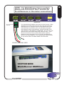
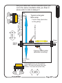
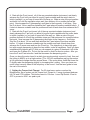
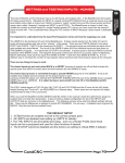
NOTE: For BladeRunner Servo system
please see the end of the F section for
the differences in the motor connections
A
Z
A1 A2 B1 B2
A1 A2 B1 B2
Y
A1 A2 B1 B2
X
A1 A2 B1 B2
HW SLAVE
A1 A2 B1 B2
IMPORTANT:
Screw Terminals
Face UP
1
!
It is important that the stepper motor wires are wired correctly. When
shipped from the factory the motors are wired right and each one is
tested with the unit. Because motors for other products we sell are
wired differently it’s possible a motor you order after the unit has
been shipped could be wired differently. DO NOT ASSUME THAT
THE COLOR OF THE WIRES IS CONSISTENT. We order wire from
different sources and cannot always define the wire colors. If you
take the connectors off for any reason either mark the wires by
position or use an ohmmeter to test for coil pairs (see Bladerunner
Manual PartII Service Manual). If you use any other motor or rewire
for any reason CHECK TO MAKE SURE THE COILS ARE
COLOR CODE MAY VARY
MOTOR SIDE
BladeRunner ESPII box
CandCNC
Page 37
E
E
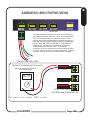
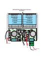
BLADERUNNER G251-4 MODULE FRONT PANEL FUNCTIONS
A
Z
Y
A1 A2 B1 B2
A1 A2 B1 B2
A1 A2 B1 B2
HW SLAVE
X
A1 A2 B1 B2
A1 A2 B1 B2
IMPORTANT:
It is important that the stepper motor wires are wired correctly.
When shipped from the factory the motors are wired right and
each one is tested with the unit. Because motors for other
products we sell are wired differently it’s possible a motor you
order after the unit has been shipped could be wired differently.
DO NOT ASSUME THAT THE COLOR OF THE WIRES IS
CONSISTENT. We order wire from different sources and
cannot always define the wire colors. If you take the
connectors off for any reason either mark the wires by position
or use an ohmmeter to test for coil pairs (see below). If you use
any other motor or rewire for any reason CHECK TO MAKE
1
!
COLOR CODE MAY VARY
TESTING FOR PROPER MOTOR HOOKUP
Motor DC resistance per coil is
less than 50 ohms
Low OHMS
0.0
OHMS
Low OHMS
OPEN (no OHMS)
On OPEN most DVM’s show “OV”
Put meter on lowest OHMS scale
CandCNC
Page 38
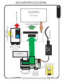
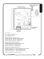
BASIC BLADERUNNER AIO BLOCK DIAGRAM
E
SWITCHED POWER
48V 12A MODULAR
POWER CONTROL
See next page
UBOB
AC Line Cord
Universal
Power
Pak
G251-4 Card
AXIS I/O
TABLE I/O
Table I/O
Multiple Inputs
Switches, probes, sensors
Connections to Motors
Expansion Module Option
DTHC
or
ISS-02
TO PC Port1
CandCNC
To PC Serial
(See Text)
Page 39
E
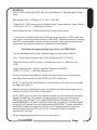
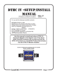
CrossFlow FAN
OPTION
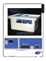
BladeRunner AIO Cover Removed Inside View
UBOB III Advanced
Breakout Card
TABLE I/O
CARD
G251-4 Motor Driver
G251-SOLO
5th Axis OPTION
CandCNC
DTHC EXPANSION
MODULE OPTION
FAN-FUSE
END PLATE
Page 40
E
CandCNC
ESP II
Enhanced Smart Power
ON
OFF
ON
OFF
DRIVE +5VDC TEMP POWER DRIVES TEST
FAULT
FAULT FAULT
OK
OFF
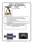
BLADERUNNER AIO FRONT PANEL
[Enhanced System Power II]
Located on the Front Cover of the ESPII Enclosure, the FRONT PANEL is
the Operator Interface for the ESPII and provides tactile pushbuttons to
turn the DC power to the Motors ON/OFF. The FRONT PANEL is a
SMART CONTROL utilizing a powerful microprocessor that monitors and
controls the power section of the BladeRunner AIO. The ESPII monitors
critical parameters, controls ON/OFF, and will automatically shutdown in
microseconds in the event of a fault. The ESPII monitors/controls:
1. System DC status
2, System Driver Status (enable/disable drives)
3. DC voltage level (overvoltage shutdown)
4. DC current (load) level (overload shutdown)
5. Internal Temperature (overtemp shutdown)
6. System Fault Indicators (LED’s and Screen Text)
CandCNC
Page 41
Normal Power up sequence:
1. Operator turns on MAIN POWER SWITCH. +5VDC LED comes on; RED OFF LED
comes on; DRIVES OFF LED comes on. All LEDS may sequence on once during processor
turn on.
2. Operator pushes ON Button. ON LED turns Green OFF LED goes off. Power comes up
on DC bus. Approx 2 sec later Drives OFF LED goes off and MOTORS LOCK
ON Button:
OFF Button:
Sends Signal to
Processor to turn
on DC Power to
the Motors.
CandCNC
ESP II
Enhanced Smart Power
ON
ON LED
On Green
whenDC power is
on.
Sends Signal to
Processor to turn
OFF DC Power to
the Motors.
OFF
ON
OFF
OFF LED
On RED when DC
power is OFF
DRIVE +5VDC TEMP POWER DRIVES TEST
FAULT
FAULT FAULT
OK
OFF
Power Dashboard. Displays status and FAULTS
See Chart on next page to decode FRONT PANEL
indicators
IMPORTANT INFORMATION: The ESPII provides multiple levels of
protection for the system and the motor drivers. Electronic fusing will
shutdown power in milliseconds as opposed to conventional fuses.
The Primary AC has two levels of control. The MAIN POWER
SWITCH and the in-line SAFETY RELAY (controlled by the FRONT
PANEL. The Safety RELAY controls AC power to the DC power
supply section. Besides Electronic fusing the system also provides
failsafe conventional fuses/breakers. There are two levels of
conventional fusing on the DC power side. The locations and values
of the conventional fuses are in the ESPII service Manual.
CandCNC
Page 42
E
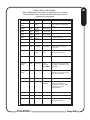
FRONT PANEL LED LEGEND
Note: LED!s flash several times on intial power up. Pushing
recessed TEST button will test all LED!s and show common
patterns for comparison
INDICATOR
Color
DRIVE
FAULT
RED
DRIVE
RED
DRIVE
RED
DRIVE
STATE
1 flash
/pause
MEANING
X Drive Fault
NOTES
A Drive Fault indicates a shorted
motor/cable or a failed Motor
Driver.
Y Drive Fault
RED
2 flash
/pause
3 flash
/pause
4 flash
/pause
DRIVE
RED
5 flash
/pause
5th Drive Fault
+5 VDC OK
GRN
ON Steady
+5 is ON/OK
Shows power on and logic
supply OK
TEMP FAULT
RED
1 flash
/pause
Case Temp
Fault
Internal Case Temp is too high.
Check fans and filters
POWER
FAULT
RED
Fast Flash
Power
Overload
DC POWER
Too Much Current drawn Auto
Shutdown. Overload of power
Module(s)
POWER
FAULT
RED
Slow Flash
Over Voltage
DC Volts Exceed max for safe
operation. Line surge or back
EMF. Auto Shutdown
DRIVES OFF
YEL
ON Steady
Drives
Disabled
Only on BladeRunner. Shows
drives are freewheeling
(disabled). Normal condition
during.power up and
faults/shutdown
TEST
YEL
ON Steady
Test Mode
Unit is in self test
TEST
YEL
Flashing
Config Error
MODE Configuration error or
unplugged module.
CandCNC
Z Drive Fault
A Drive Fault
May indicate misconfigured
Slave Axis Setup
Page 43
E
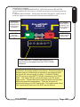
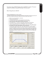
Load and Testing MACH
F
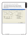
After you have installed MACH and run the BladeRunner INSTALL on the Support CD,
open MACH3 using either the MACH Loader and the BladeRunner selection from the list
OR using the BladeRunner Icon created in the desktop.
You should see the following screen or something very close. If you are missing the
Desktop icon or it’s not in the selection list, re-run, the INSTALL again. If you have the
Profile (BladeRunner) listed in the MACH LOADER and the screen does not display, go to
the top menu bar and select VIEW/Load Screens and navigate to the MACH3 folder and
select BladeRunner-Router.set. If it is missing any of the Bitmaps (picture buttons and/or
backgrounds) then confirm the Installer created the CandCNC folder under the
MACH3/Bitmaps Folder and there are files in that folder. We have included a Zip file on the
CD of all the bitmaps and the ZIP file is on the CandCNCSupport Forum site in the
FILES/BladeRunner Support Files Folder. You can UNZIP the files in the Bitmaps.ZIP file
directly to the MACH3/Bitmaps/CandCNC folder. Along with bitmaps and other features the
BladeRunner screens contain several custom functions embedded as code behind certain
buttons. If you elect to use another screen SET file with the BladeRunner be aware some
functions will not work. The DTHC screens have specific functions and the DTHC
functions will not work on other screen sets.
CandCNC
Page 44
F
CUSTOM CandCNC Screen SET provided with
BladeRunnerAIO UBOB3 install file. Some features may
change over time. DTHCII specific functions are covered
in detail in the DTHCII User Manual
BladerRunner DTHC
PLASMA PROFILE SCREEN
CandCNC
Page 45
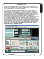
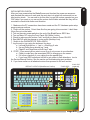
Screen Sections explained
F
MACH3 TOP MENU. POPS up windows on top of the screen to access various settings. Three most
used are: 1. Files 2. Config 3 View. This menu row is visible and can be accessed from all screens
MENU SCREEN SELECTION. Consists of tabs to select different screens. In normal run mode the
PROGRAM RUN screen is the most used. The DIAGNOSTICS screen is used to confirm proper settings
and functions and will be covered later
DRO (Digital Readouts) for axis position and for manual referencing and zeroing the DRO’s
REF buttons move an axis towards an associated HOME switch. When the axis hits the switch
It will stop and backup slightly. If it moves the wrong way or does not move at all see the section
on CONFIG/HOMING & LIMITS
Current G-Code File Loaded or running
RUNNING PROFILE Box Shows the current MACH PROFILE you have running.
Function Buttons allow
control of the G-code,
Loading and Closing Gcode and a rewind to the
start button
REF XY Button,
performs a REF move
on XY at the same time
but not on Z. Useful on
plasma after the first
REF has been done to
locate 0.0
JOG ENABLE Button
Turns keyboard jog on/off
(should stay on normally)
FRO Feedrate Override
changes feedrate on all
Axis at the same time
CandCNC
Loaded/Running G-code
screen shows g-code as it is
executed. Stopped code can
be scrolled and new start points
selected. The code can be
Edited using the Edit G-Code
Button
Function Buttons allow control
of the G-code, Loading and
Closing G-code and a rewind to
the start button
LOAD MATERIAL button
initiates a move to a preset
postion
OUTPUTS ON/OFF Buttons
Turns on/off the two AUX relays
(table i/o Card). Bladerunner AIO
has two wired AC sockets that are
controlled from these buttons
Page 46
F
DTHCII SCREEN SECTION.
A detailed breakdown of all the buttons
functions and readouts on the DTHCII section
are covered in the DTHCII User Manual
(separate manual) Only general descriptions are
covered here.
UP/DWN and Send to DTHC Button. Any value
typed into the PRESET VOLTS and ENTER is
used to lock the value inthe DRO is instantly
transferred to the DTHCII memory when the
Send to DTHC button is hit. The User/operator
can quickly change the PRESET VOLTS before
or DURING a cut and change the ARC GAP in
the process
TORCH AMPS Displays the action Cutting AMPS
IF the CandCNC DCP01 Digital Current Probe
has been installed. Otherwise it reads zero. IT IS
NOT USED FOR THE CUT CURRENT PRESET
value.
THC ON/OFF turns the THC function In MACH
ON or off. The DTHCII can turn this on
automatically when the torch fires (setting in the
Cut Profile) Operator can turn the THC on/off
manually. When THC is off MACH ignores any
commands from the DTHCII to move the Z
INDICATOR LED’s
TIP SAVER (turns on when TIP
saver is active. TIP SAVER is a
dynamic anti-dive that keeps the
torch from diving on corners or when
crossing a void or existing kerf
UP/DOWN/ARC OK shows the
statues of those inputs from the
DTHCII. These are the
COMMANDS from the DTHCII to
MACH.
DTHC ONLINE shows the
communication status of the DTHCII
module to MACH3. It MUST be on
to allow MACH to display screen
values and to allow Cut Profiles to
transfer to the DTHCII
CandCNC
TORCH ON/OFF toggles the torch (OUTPUT1)
on/off manually from the screen. The torch can
be turned on or off at any time MACH is out of
RESET....even during a run
STORED SETTINGS (CUT PROFILES). This
button opens a window that displays a range of
values and settings for the DTHC to use. The
initial display is of the CURRENT SETTINGS in
the DTHCII memory. Profiles by material can be
recalled. selected and added. Detailed use of the
CUT PROFILES is covered in the DTHCII User
Manual
IMPORTANT: There are Self-Tests that can be
preformed on the DTHCII modules and other
modules in the setup. They establish that the
modules are functional and sending data to
both the parallel port inputs and the PC serial
input. If you do not have proper display of
values while cutting or the DTHC ONLINE is
not ON you are missing critical signals. See
the DTHCII User Manual to run the tests
Page 47
F
POWER SUPPLY DASHBOARD. Displays realtime values of the
ESPII Smart Power systems used in the BladeRunner controllers.
All critical parameters are monitored and if a level reaches a point
that is too high it will trip a fault and shutdown the power to the
motors. Faults will display in the FAULT MESSAGE BOX (previous
page)
CASE TEMP: Internal temperature of the
BladeRunner enclosure In deg F.
VOLTS Power
Supply DC Volts.
Displays power
supply voltage to
motors (ESPII
Smart Control...
only on when DC
power is on.
DRIVE TEMP- NOT
USED
Dynamic Load Bar Graph
FEEDHOLD Pauses
G-Code at end of
buffer. Leaves outputs
active
AMPS shows the
total current drain of
ALL motors that are
attached. Current
increases with the
load on each motor
STOP Stops Gcode execution
instantly (dumps
buffer) Turns off
ouputs
RUN (Cycle Start)
runs g-code that
is loaded . Will
restart g-code if in
PAUSE or STOP
NOTE: To stop gracefully (no lost
position) use the FEEDHOLD and
after machine motion has ceased use
the STOP.
CandCNC
RESET (Toggle
ON/OFF) Stops all
code, Turns off all
ouputs, Stops any
macro. Turns off
Charge Pump
Toggle turns
Page 48
F
FAULT - ERROR Message box. Scrolls FAULT messages from CandCNC ESPII and other
“smart” devices. Shows drive faults, Power Faults and Hypertherm Fault messages for
units equipted with otions RS485 port and optional HyT-Connect RS485 SIM Kit.
ERROR messages are information and critical messages from the MACH system.
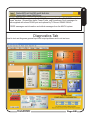
Diagnostics Tab
Used to test and diagnose general Input and output problems and to do test runs.
CandCNC
Page 49
F
AXIS CONTROL Diagnostics: Has the same DRO’s the same Axis ZERO buttons
and manual REF buttons as the Program Run Screen so the User can see the
numbers without have to flip back and forth. When troubleshooting you can see
activity on an axis and do setup if needed.
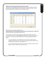
INPUT STATUS BOX: Shows the Inputs as they are mapped in MACH. The Inputs are
YELLOW when ON (active). The inputs should all be OFF (grey) when the system is first
turned on and MACH is out of RESET. There MAY be an Emergency (E-STOP) on if the DC
power to the motors is off on the BladeRunner. The Limits will seldom light because as soon
as a LIMIT goes active, to puts MACH in RESET and the INPUTS are no longer displayed
correctly. It turns the LIMITS OFF as soon as the LIMIT goes active. The indication a LIMIT is
working is if when hit it puts MACH into RESET. The setup or HOMEs and LIMITS will be
covered in later in this manual. Use the INPUT Status to test the individual inputs. Please
note that Inputs FIRST hit specific pins on the parallel port and the MACH PROFILE
determines what each one does so if you have inputs that are not correct the first thing to
check is the RAW PAORT INPUT BITS on the following pages.
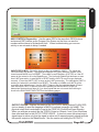
OUTPUT STATUS: Displays the status of the OUTPUTS/ Active outputs FLASH RED
(not on steady) It uses the mappings in MACH to activate a specific out NAME. The
physical output that is matched to is set in the PROFILE (Ports&Pins/Ouput Signals)
When you activate an output like the TORCH Output or Outputs 1 and 2 you should see
them start and flash in the OUTPUT STATUS BOX. It does not mean the actual output
signal name is active only that the signal is active and if mapped properly should activate
the specific output on the BladeRunner. See the section on setting the OUTPUTS
CandCNC
Page 50
OUTPUT Status (Cont). There are two AUXILLARY OUTPUT Relays on a
BladeRunner AIO unit. They are designed as Output 1 and Output 2 on the Buttons
and they toggle ON/OFF the AC Outlets A and B on the end of the BladeRunner Box.
These AC outlets are wired to the AUX AC line cord on the BladeRunner. That cord
must be plugged in before the outlets can be used. CAUTION there is high voltage
(120VAC ) at the Relays and the Outlets. DO NOT OPERATE THE BLADERUNNER
WITH THE AUX AC CORD PLUGGED IN AND THE TOP COVER REMOVED.
NOTE: The number of output relays can be expanded by adding in a Quad Relay
Expansion card but is seldom used so connections and setup are not covered here
On a BladeRunner Dragon-Cut (with DTHC) OUTPUT 1 in MACH is used to turn on
the TORCH Relay located out in the THC SENSOR PWM. Operation is covered in
depth in the DTHCII User Manual but it is easy to simply plug in the THC SENSOR
PWM module to the DTHCII module using the 25ft UTP Cable and test the TORCH ON
by toggling the TORCH button on the Diagnostics Screen and watching the TORCH
LED on the front of the THC SENSOR PWM module. You can test the other two AUX
outputs by plugging in the AUX AC cable and plugging in an AC load (table lamp,
120VAC FAN . etc) and toggling the individual outputs on and off.
The AUX outlets can also be turned ON and OFF from G-code using an “M” command.
What M command is used to turn on/off an OUTPUT is a setting in MACH and comes
defaulted so a M03 or M04 turns on OUTPUT1 (Torch on the Plasma Profile, Spindle
on the Router Profile.) M05 turns OFF either. In a full Spindle Speed System the M04
turns ON the REVERSE RELAY.
The two AUX Relays (See Setting Outputs Section) are located on the TABLE I/O.
Control OUTPUTS
from
DIAGNOSTICS
SCREEN via the
Toggle Buttons for
each output,
NOTE: Only 3 Outputs are availaible on a BladeRunner AIO
Dragon-Cut (Large buttons above). The Router setup only has 2
outputs available.
CandCNC
Page 51
F
F
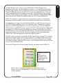
Diagnostics Screen allows you to LOAD
and RUN G-CODE files and to see the
scrolling G-CODE. To load a G-Code file
move to the top tool bar and FILES/Load
GCode and select the file to load. It will
appear in the G-Code window. There is a
small Toolpath display under the G-CODE
window and the dispaly can be turned
ON/OFF with the buttons under it.
To RUN, Feedhold, STOP, Rewind of
SINGLE STEP from the Diagnostics
Screen use the Buttons shown.
There are status LED’s for UNITS and to
show running status and Dwell.
USING SINGLE STEP TO TROUBLESHOOT
CODE:
Often a mistake in G-Code or the setup is hard to
spot because it runs faster than you can watch the
machine and the code execute. The SINGLE
STEP can help with that. It puts MACH in “Single
Block mode” which means it will execute ONE
LINE (block) of G-Code at a time. It does this by
clicking the RUN button each time you want the
next line of code to execute. On a plasma we
recommend you turnoff the plasma and disable the
AUTO THC ON (Cut Profile) before using the
SINGLE button. With the SINGLE Button on (LED
ON) you can run a line, watch the moves, take a
measurement if needed and see if the motion is
correct.
CandCNC
Page 52
F
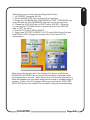
Other things you can control from the Diagnostics Screen:
1. JOG ON/OFF (unusually left ON)
2. Set the SINGLE STEP Jog Increment (Cycle Jog Step)
3, Change the JOG MODE from CONTINIOUS to STEP. STEP MODE only
moves the axis the JOG INCREMENT each time you hit the Jog button.
4. Change the SLOW JOG rate (no SHIFT with a JOG KEY = Slow jog).
You can use the UP DOWN buttons or type in the value in the DRO (hit
enter to “SET” the value)
5. Turn the THC Logic in MACH ON/OFF
6. Enter a new TIP VOLTS (PRESET VOLTS) value [Enter Key to Set] and
then SEND to DTHC (change the running value in the current DTHC
configurations
While most of the controls are on the Program Run Screen of MACH the
DIAGNOSTICS SCREEN lets you monitor inputs/outputs and position while
running manually or via code. While there is a lot of information and buttons it
offers the feedback you need when doing the intital setup or troubleshooting of
a system. Earlier in the PC Hardware Section you see how the RAW PORT
INPUT BITS shows if the Parallel Port is properly configured and respondiing.
CandCNC
Page 53
SETTING UP MACH3 FOR BLADERUNNER
When you install the BladerunnerAIO-UBOB3-Install.exe file (auto installer) it
automaticaly sets up two profiles in MACH, One for Router and one for
Plasma with DTHC interface. The following pages will go though how to test
and change any of the default settings for your specific table.
There are several sections of the MACH CONFIG that we will cover. The
access the MACH3 direct configuration menu find the TOP Menu on the
screen and click the CONFIG select in the Drop Down Menu
The selections in the CONFIG
Drop Down Window (DDW)
consists of several sections.
Most of them are not used
setting up a BladeRunner
Profile. If you don’t know what
a function is DO NOT change it
unless you make a copy of
your Profile and perform the
changes on it. Making changes
to see what it will do is
dangerous because cetain
settings are critical to the full
operation of UBOB III.
A note here about configurations and MACH3
The config menu is a user interface to make changes to the current MACH3
PROFILE you are running. Each Profile has it’s own file with settings. Virtually
every setting is stored in that PROFILE. Things like Motor Tuning, Ports & Pins
and even which Screen Set it uses are stored. If you make a change in one
profile it DOES NOT propagate over to another profile’s settings!
If things get really messed up you can reload from the INSTALL file off the CD
but if the PROFILE name is the same then the settings go back to the Defaults.
Each time you make a change in CONFIG it gets stored in an XML file with the
same name as the displayed Profile in the Program Run screen. IT ONLY
SAVES THE RUNNING PROFILE WHEN YOU CLOSE MACH NORMALLY.
MACH only reads the Profile when you start it up to a specific profile. Some
settings will change the RUNNING profile (what you are currently running)
OTHERS DO NOT. Plugins are only read once when MACH is started so a
chage to a plugin config will require you stop and restart MACH3.
CandCNC
Page 54
F
F
CHECKING MACH3 CONFIG for Proper PORT1 ADDRESS
In the PC Hardware Setup Section the PORT 1 Address was determined.
Use the CONFIG/Ports&Pins menu to check the address and if needed
change the settings. Note PORT #2 is disabled. Default Kernel Speed is
45000HZ which will work with most PC’s and will provide pulse rates for any
BladeRunner setup.
CandCNC
Page 55
CHECKING AXIS MOTION (4 Motor systems)
Setting up the Software Slaved Axis. BladeRunner 300-4 and 620-4 are shipped with 4
motors but the A axis is NOT SLAVED in the default setup. You will need to decide
the axis naming convention you will be using for X & Y. There are several schools of
thought here. The old convention is to call the “long” axis X and the short axis “Y”.
This can make for some confusion as to how to layout files to be cut if the operator
station is not facing perpendicular to the long axis. Our approach has always been to
use the computer screen layout where the vertical (UP and Down) on the screen is Y
and the horizontal on the screen (side to side) is X. That is the way the software will
want to designate the axis on the computer by default. In the following pages we show
typical setups and operator position. The goal is to have the toolpath oriented the
same way as it shows on the computer drawing in relation to where the operator stands
at the table. The recommend placement of HOMES is based on the fact that normally
the lower left corner of the drawing is defined as the 0, 0 (origin) of the drawing and the
resulting G-code from the CAM if it follows the same convention.
!
NOTE: IF YOU HAVE A 4 MOTOR SYSTEM, the A axis should be software slaved
to the axis you have designed as the Gantry motion axis (X or Y). We do not have
that setting as a default because we do not know which axis you will designate as
the gantry motion axis.
To slave the axis in software: Open MACH3 CONFIG/AXIS SLAVING
Select the Axis you wish to slave the A to (X or Y and click the A radio button on that
axis.
If you have a 5 motor system. A 5 axis slaved (sometimes called a 4.5 system)
Hardware slaves the 5th motor/driver using settings on the UBOB card. Factory
default is for the 5th axis to be slaved to the Y motor and turn in the opposite
direction. The above Slave Axis Selection is set to None on all axis (no slaving).
The A axis then is independant and is activated for testing with the numeric pad +
and - keys by default.
Page 56
CandCNC
F
Set your table and control console up so you
cut in the same orientation that you draw in
where side to side is always X
X, Y Homes
0, 0
Z axis w/ torch holder
X axis
If you stand here to run the machine
then 0, 0 is lower left corner from your
location. X is cross axis (long axis)
Typical rectangular
table setup
4 motor setup (dual drive
on the gantry)
Master
Motor
Slave
Motor
GANTRY
Z axis w/ torch holder
(alternate mounting)
X, Y Homes
0, 0
If you stand here to run the machine
then 0, 0 is lower left corner from your
location. X is cross axis (short axis)
X axis
CandCNC
F
Page 57
F
Hardware Slaving Options.
ONLY USE THIS PAGE IF YOU HAVE A 5th AXIS CARD INSTALLED or INSTALL ONE LATER
Even if you decide not to use the 5th axis the unit is shipped from the factory setup to use the
5th axis as the default Slave axis (HARDWARE SLAVE) If you decide NOT to use the Hardware
Slave and instead want to use the A axis as a software slave then YOU MUST break the Hardware
Slave using the Jumper Settings below. If you elect to ignore the instructions and leave the settings
as a Hardware Slave and try to use the A axis hardware slaved also, you will get DRIVE FAULTS on
the (unused) 5th axis.
5 AXIS SYSTEM
FACTORY DEFAULT
Hardware Slave shown in “Y” Position
Both OPTION BLOCKS MUST be jumpered
the same.
1-2 External drive FROM PORT2 card
3-4 Slave 5th Axis to X
5-6 Slave 5th Axis to Y
1
2
J63
2
Factory Default setting if
5th axis not used. Do not
change unless you are
going to use a 5th driver
and motor.
1
4
3
5
6
5
6
DIR
5
1
2
1
J63
2
4
3
6
5
6
Axis Slave
STEP
4 AXIS SYSTEM
FACTORY DEFAULT
AXIS I/O
1
In order to run 5 separate (independant) axis (not hardware slaved)
you have to install and setup a 2nd parallel port card in your PC
and interface it through our OPTIONAL Port2 Interface Card. See
the addendum section for information about the Port 2 Interface
THE UBOBIIII card in the drawing is located in the Top of the
BaldeRunner AIO unit, The PORT1 and COM1 connecors stick
through the apnel on the right side of the enclosure, see the photo on
page ___tp locate the UBOB Card
CandCNC
Page 58
F
ONLY USE THIS PAGE IF YOU ARE GOING TO DRIVE A 5th MOTOR FROM THE
MTA150 Card. or in the BladeRunner It sets up what that output (B) does. If you want to
SOFTARE slave an axis that is done in MACH3 in the Axis Slaving under CONFIG.
TABLE I/O
1
26
Pull pin 26
+9 FLT
U55
+
1
U1
J53
1
PLUG
U7
J53 REAR
SERIAL
U10
C5
+
CandCNC
UBOBIII
REV5
U5
AXIS I/O
1
GND +12
DTHC
AXIS
I/O
Pull pin 26
EXPANSION
+
16
15
J4
2
R6
RN1
1
J63
+12
J9
AXIS
OUT
J65
POWER
PORT2
SIP2
EPO B-PASS
J6
RN2
+
+
25
U2
SIP1
U3
1
1
J2
24
See previous
page for Hardware
slaving option
jumpers
PORT2 INTERCONNECT
J57
FAN
1
TABLE I/O
J3
C11
J1
1
14
PLUG
PPORT1
+
PARALLEL
U51
SERIAL
+5
+
CandCNC
UBOBIII
1
SIP4
DIR OPTION
NORM REV
J5
1 2 3
REV5
SKT
J29
DIRECTION POLARITY JUMPER
(New on UBOBIII REV5 cards)
This option is used ONLY if you are hardware slaving the 5th axis option from the X or
Y. It allows you to change the direction of rotation of the 5th motor if needed. You can
reverse a stepper direction at the motor simply by swapping the polarity of one coil
(out of the two) Wile that works for steppers you cannot reverse the direction of a
servo that way. We have added the Direction Polarity Jumper to allow you to reverse
the DIR signal polarity in hardware. To reverse the direction simply move the jumper
from 1-2 to 2-3 position,
DIR OPTION
NORM REV
J5
1 2 3
CandCNC
Page 59
INITIAL MOTION CHECK:
After you have powered up the BladeRunner and checked the power on sequence
and checked the motors on each axis the next step is to plugin all motors and run an
intial motion check. You can wait to do this after you get the motors mounted on your
CNC table if you want or you can set the motors on the table oriented like they will be
mounted to check inital motion and direction.
1. Make sure the PC connections have been made and the PC Hardware ports setup
as per previous sections.
2. Plug in all the motors. Orient them like they are going to be mounted. Label them
if they are not on the table.
3. Turn on the main power switch on the end of the BladeRunner ESPII box.
4. Turn on Motor DC using the Front Panel ON (White ) button.
5. Check to make sure the motors “lock” and that you have a Green ON LED
6. Start MACH3 with the plasma or router profile (desktop Icon).
7. Switch to the DIAGNOSTICS TAB in MACH
7. Jog the axis in turn using the keyboard Jog keys
a. Left and Right Arrow --> and <-- should jog X axis
b. Up and Down Arrow should jog Y axis
c. PageUP and PageDown should Jog Z axis
8. STOP! If you cannot get an axis to move or or it only moves in one direction:
a. Check to make sure the associated DRO is changing on the screen
b. If it is then check all of your cables from the parallel port
c. If you have DRO action and still fail to get motion in both directions, turn to
the Service Manual Section. See the section on troubleshooting port problems.
9. If you have motion on all attached motors then proceed to the next section
DEFAULT HOTKEYS (BladeRunner Profiles)
F1
Esc
~
!
1
`
Tab
@
2
Q
Caps
Lock
Shift
Ctrl
F2
F3
#
3
$
4
W
E
A
S
Z
F4
%
5
X
^
6
R
D
T
F
C
F5
G
V
Alt
F6
F8
&
7
*
8
(
9
Y
U
I
H
B
F7
J
N
M
F9
F10
F11
|
\
)
0
_
+
-
=
O
P
K
L
<
,
>
.
{
[
:
;
}
]
Print
Scrn
SysRq
Scroll
Lock
Insert
Home
Page
Up
Delete
End
Page
Down
Pause
Num
Lock
Break
"
'
?
/
Alt Gr
F12
A Axis JOG
(unslaved)
Z JOG KEYS
Shift
Num
Lock
/
*
7
8
9
Home
p
PgU
4
5
6
1
2
3
End
Ctrl
Caps
Lock
Scroll
Lock
-
+
PgDn
0
.
Ins
Del
Enter
AXIS DRO’s
ENTER KEY
XY JOG KEYS
AXIS DRO’s
CandCNC
Page 60
F
LINEAR MOTION WITH RACK & PINION
Pressure Angle
F
Pitch Diameter
R
OD
RACK
TYPICAL SPUR (PINION ) gears
Psr = Pinion Speed increase ratio = Pitch Dia [in inches] * PI (3.1416)/1
= Pitch Dia [in mm] * PI (3.1416)/25.4
Example: 1” Pitch Dia pinion will have a step up ratio (speed increase of 3.14
(approx 3)
Belt reduction decreases speed by Raw Speed /Belt Reduction Ratio
Belt reduction increases linear force by normal force X Belt Reduction Ratio
Raw Motor Resolution = 1/200 = .005” linear [.127mm]
Final linear resolution = .005/Belt Reduction Ratio
Belt Reduction Ratio =
R2/R1
Numbers for direct pinion drive are
:simply Psr * Motor RPM = IPM
(speed)
Torque(oz) = T1/ R3
P2
Linear Force
R1
R2
P1
R3
P3
FIXED
Forces:
T1= Rated motor holding torque (Oz-in) / R1
T2 = Shaft holding torque of P2 = motor holding torque * Belt Reduction Ratio
T3 = Torque(oz-in at pinion (teeth) = T2 * R3
Note: Motor torque decreases with Motor RPM so a number of about 50% of the holding torque
Motor constants: (based on stepper motors provided by CandCNC)
Typical RPM of hybrid steppers (moderate load) with different DC power
24 VDC = 300 RPM
48 VDC = 600 RPM
65 VDC = 800 RPM
Number of steps for 1 motor REV = 2000 (this a fixed number based on Microstepping X10)
CandCNC
Page 61
F
EXAMPLES
620 oz-in Stepper motor @ 48 VDC with 1” dia pinion gear & direct drive:
Max possible IPM = 600rpm X 3.142 = 1885 IPM
* 50% RPM linear force = 50% Stepper motor torque / pinion Radius/ Pinion Speed
Ratio = (310Oz-in/.5in) / 3 = 206.66 linear oz of force
Same design but with 3:1 belt reduction from motor to pinion shaft:
(310OZ-in/.5in)/1 = 620 linear oz linear force.
* in the above calculations the motor RPM and torque numbers of 50% were used
to operate the motor in the center part of it’s torque-RPM curve.
Calculating the beginning Steps per UNit on an AXIS
Use the following formala to get a ballpark steps per unit number in MACH
Psr = Pinion Speed increase ratio = Pitch Dia [in inches] * PI (3.1416)/1
Target Steps per Unit = (Psr X 2000)/Belt Reduction ratio
This will give you the required number of steps it takes to move 1”
Once you have the calcualted number of steps it takes to move the axis one inch
then put that number into the STEPS per UNIT of the motor.
Based on the speed numbers you have calculated from the previous pages set you
velocity to a vlaue of 60 to 80% of that number.
Set your Beginning Acceleartion to a low number like 10
To fine tune the calibration see the next pages.
CandCNC
Page 62
F
Setting the initial Steps per Unit in MACH3 motor tuning.
Every table will have different Steps Per Unit, Velocity (max speed) and Acceleration settings. To do
testing on the table you must determine the correct settings for your table. Use the following method:
For Steppers:
1. Determine the number of steps your motors need to make one full revolution (Normally
200 for most steppers)
2. Multiply by the Motor Driver microstepping rate (10 for BladeRunner/Gecko drivers) =
2000 steps for one motor revolution.
3. Determine the drive ratio of your mechanical drive (how far does the leadscrew or pinion
move the load with one revolution of the motor).
4. Convert everything to you Units (inches/millimeters) and same time measurements
(seconds or minutes).
Using 1 and 2 above we know we have to send 2000 pulses (step pulses) from MACH to rotate the
motor one complete revolution (360 Degs).
The rest of the math is based on the transmisson ratio(s) between the motor and the final drive element.
If it's Rack & Pinion you need to know the DP (diametric pitch) or the tooth count of the pinion gear and
the TPU of the Rack (Teeth per unit)
If it's a direct drive leadscrew you need to know the treads per unit (TPI for inch units)
We have to determine how far the load moves (in units) for each REV of the motor.
Lets do a direct drive leadscrew of 5 TPI :
It takes 5 turns to move the load one inch of linear movement so the steps per inch (unit) of the axis is
simple: 2000 [number of steps for one rev] X 5 [number of Rev to move one inch] = 10.000 steps per
inch. (.0001”) resolution. About 6 to 7 times the torque. 1/5th the motor Speed.
Now let's do a R & P direct drive and an R & P with a belt reduction transmisson:
For a R & P the distance traveled per rev of the pinion is given by the DP of the pinion X PI [3.1416].
Ifwe use a 1” DP pinion the distance traveled is 3.1416” per rev of the pinion So a direct coupled motor
gives us over 3” of travel per rev. To get it back to a Unit (1 “) it would be the number of steps (2000 from
above) / 3.1416 or 636.6183….as you can see, the resolution at .00157 per step is MUCH courser than
the 5 TPI leadscrew. The max velocity (speed would be over 8 times the leadscrew but with 1/3 the
torque of the motor specs) is over 2000 IPM.
To gain back the lost resolution and torque you should belt reduce between the motor and pinion. With a
5:1 ratio you would see the numbers change to:
2000 /3.14165 X 5 or 3183.1 steps per inch (.000314 inch). Torque would be 1.66 times greater than
motor rated torque.
NOTE: DO NOT use the microstepping in a “true” resolution calculation for accuracy. Microstepping is
for motion smoothness and cannot be counted on to actually position the motor shaft at a fraction of a
motor pole (between poles). It can be off and the faster the motor spins the less effect microstepping
has. The only true resolution will be the 200 steps per rev of the motor. In practice it will be somewhat
better especially at slower RPM but it varies.
CandCNC
Page 63
F
For proper tuning of MACH3 please refer to the MACH 3 manual. The exact
tuning of the software is beyond the scope of this document.
Motor Tuning Screen in MACH3
Testing the BladeRunner for motor control
. In order to get motion and you need to have MACH3 running with it out of E-stop and the CP
LED on the front panel active (ON). Without CP active, you will not get motion.
·
·
·
·
·
·
·
·
·
Make sure all of the cables are connected.
Power up the BladeRunner
Load Mach3 with the proper profile (BladeRunner) and Screen
Turn on DC Motor power using the ON button on the Front Panel
Motors should “lock” when power comes on to the motors
Hit the Reset button. The LED over the Reset in MACH will turn solid Green
The CP LED on the front panel of the BladeRunner will turn solid Yellow
Use the keyboard arrow keys to jog your machine. Don't worry if they jog the wrong
way with the keys or the wrong axis jogs. We will fix that later.
The Optional test Step and Direction Monitor will confirm that the signals are getting
out to the EzPlug G251-4 Driver card. If the LED's flash and you are not getting
movement the problem at and the motor drivers. Check your cables and connections
carefully. The DB connectors need to be seated and the holding screws tightened for
each cable. Sporadic motor movement or direction changes (without changes at the
Step & Direction Monitor indicates one winding on a motor may not be making good
connection
CandCNC
Page 64
F
SETTING MOTOR DIRECTION
At this point you should have motion on all axis using the Keyboard keys to scroll with.
In this section we will set the direction of motion for each axis and match the keyboard
keys to that motion.
IF YOU HAVE THE MOTORS ON THE BENCH AND LABELED YOU WILL NEED TO
ORIENT THEM LIKE THEY WILL BE MOUNTED ON THE TABLE AND WATCH THE
DIRECTION OF TURN OF THE SHAFTS. IF YOU DECIDE TO MOUNT THE
MOTORS ON THE TABLE YOU SHOULD DISENGAGE THEM FORM THE TRAVEL
MECHANISM UNTIL YOU GET ROTATON DIRECTION RESOLVED. THIS IS
ESPECIALLY TRUE FOR THE SLAVED MOTOR ON THE GANTY AXIS
1. Load MACH and the BladeRunner Plasma or Router Profile
2. Load the Diagnostics Tab
3. Power up the BladeRunner AIO and the DC to the motors
4. Move Each axis several inches away from the Table 0 (home switch) positions5. Zero
each DRO with Zero Button next to each axis.
5. Jog the Z first. Note the Z DRO as it moves UP.
a, If the numbers are INCREASING in value then the direction is correct.
b. If the numbers are DECREASING then the DIR is wrong. See the next page to
change the DIR of a motor
c. The key may not match the direction of jog...do not worry it will be redefined
7. JOG the non-slaved axis next and do the same DRO check and change if it is scrolling
the wrong direction.
8. The Slaved Axis is a little different. You must FIRST setup the slaving (See Page ___
earlier in this section) using the 4 axis or 5 axis instructions.
9. The DIR setting on the SOFTWARE Slave (A is slaved to Master axis) is opposite the
Master axis (motor faces the other and spins opposite to move the same direction)
Hardware Slaving is set via jumper on UBOB III
10. If in the setup you need to change the Master Axis DIR to make it move correclty
you will also need to change the Slave Axis on a 4 axis (Software Slave) setup.
CandCNC
Page 65
F
Setting up the proper axis direction and motor tuning
While the Profile file (BladeRunner.XML) provided with the unit sets up all of the
pins there are several things we don't know about your machine and so certain
parameters have to be set based on your specific machine. .
Note each axis has a Step and Direction pin.
At this point do not worry if the axis moves in the wrong direction, simply that
you have the axis as you define them correct.
The next step is to make the axis movement agree with the DRO and g-code
commands for that axis. The DRO (Digital Read Out) for each axis is at the top of
the screen. You will need to take MACH3 out of E-stop by pressing the Reset
button.
·
Jog your machine so the cutting head is away from the Homes (approx
center of the table is good). Don't worry if the jog keys aren't correct or that
the DRO's are running in the wrong direction.
·
If your machine is setup so that one corner is X0,Y0 (lower left corner?) then
all moves from 0,0 should be a positive number.
CandCNC
Page 66
F
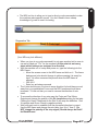
·
The MDI is a line to allow you to type in direct g-code commands to make
the machine make specific moves. You don't need to have a deep
knowledge of g-code to use it for testing.
Diagnostics Tab
(Your MDI may look different)
·
·
·
·
·
When you type in a g-code command it is not case sensitve but be sure to
use zeros's and not “O's” for the numbers! At this point do not worry
about which hotkeys are assigned to a direction.
With the machine out of e-stop and power on, type the following into the
MDI Frame:
o Move the screen cursor to the MDI frame and click on it. The frame
background color should change to yellow meaning it is ready for
input. No other movement keys work when the MDI frame is
selected.
o G00 X3.0
o Enter key activates command
The X axis should move 3 inches in some direction It should have moved
away from your established X zero and the DRO numbers should have
increased. If it did not then you need to reverse the direction of axis
travel.
To reverse the direction of any axis open the Ports and Pins/ Motor
Outputs and change the polarity of the Dir LowActive setting for that axis.
Clicking the Green Checkmark or the Red X will swap the definition. Red
X is posiive and Green Check is negative polarity.
Work with each axis to establish that the movement direction is correct.
Use the MDI frame and change the axis letter from X to Y then Z. Do
NOT change the polarity of the step signal (Should always be Red X
for BladeRunner
CandCNC
Page 67
F
FINE TUNING the calibration using the “tape measure” method
Once you have a ballpark of the number of steps it takes to move your machine 1
inch then you can fine tune that using a simple tape measure and a calculator
1. Establish a zero spot you can precisely mark on your table. On a plasma table
you need to remove the torch and either mount a laser pointer at tool center or use
a sharp pointed tool in a holder. You can also tape a small drill bit or pointer to the
torch nozzle if your mount has enough room. You want something small enough you
can see errors of .032 on the marks of the tape.
2. Setup up the axis you want to calibrate with the pointer sitting at the zero point
and zero that axis DRO.
3. Write down the Steps per Unit value you have for that axis.
4. Open MACH to the Diagnostics Page and find the MDI window
5. Type in a distance to send that axis out using the following G-Code (example is
for moving X out 30 inches) HIT THE ENTER Key to execute the line
G00 X30.000
6. Measure the ACTUAL distance you went with your tape measure from zero to
where it stopped and write down the distance to as close a decimal value as you
can (estimate the distance if it’s less than a 1/16 (.063).
7 BEFORE YOU make ANY changes move the axis back to the start point by using
the MDI and typing G00 X0.000 (for the example above)
8, Use the formula On the next page and calculate the new Steps per UNIT. Then
open the motor tuning in MACH and make the change. Run the same test again
(you should be MUCH closer. Once you are as close as you can see by eye at 30
inches do one final test at the longest point on that axis. Typically if you are within
.032 at the end of the move, you will be within 4 decimal points at 1 inch.
CandCNC
Page 68
CandCNC
D
C
B
Page
1
INSULATION CLASS
LEAD STYLE
NO. OF LEADS
HOLDING TOGQUE
RESISTANCE
CURRENT
VOLTAGE
2
1
3
4
437
B
8
N.cm
/PHASE
N.cm
A/PHASE
2 ±10
/PHASE
3.5
5.0
FF46-1/0.5
±10
A/PHASE
V
V
3.969
SERIES CONNECTION
PHASE
2
°/STEP
1.8±5
.265
FF46-1/0.5
400
B
3.5
3.5
1.8±5°/STEP
STEP ANGLE
PHASE
EIGHT WIRING
PHASE
2
unit=mm
CONNECTION WISE
V
SPECIFICATIONS
.940
.058
.375
DIMENSIONS
Dimensions in Inches
1.498
A
4
RED A
TAG PLACE
5
PROC.
CHECK
DESIGN
CHANGE
APPROVE
STD.
6
NAME
B B D D
WHT PUE BRN GRN
EIGHT WIRING CONNECTION
BLK C
YEL A
BLU C
A
A
B
B
DATE
NR
DESIGN
BIPOLAR & UNI-POLAR
7
PAGE:
MASS PLATE SCALE
SERIES CONNECTION
COLORS OF LEAD WIRES
Use # 8-32 mounting screws (4mm)
2.351
1.856
1.856
BladeRunner 620 Stepper Motor
Dimensions
2.351
.172d
8
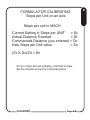
FORMULA FOR CALIBRATING
Steps per Unit on an axis
Steps per unit in MACH
Current Setting in Steps per UNIT
= Sc
Actual Distance Traveled
= Dt
Commanded Distance (you entered) = Dc
New Steps per Unit value
= Sn
(Sc X Dc)/Dt = Sn
Sn is in steps and will probably a decimal number
Set the decimal amount to 3 decimal places
CandCNC
Page 69
F
ADDENDUM SECTION ADDED 11/15/12
For BladeRunner AIO Dragon-Cut SERVO
products
The following 6 pages are for the SERVO motor version of the BladeRunner DragonCut and cover the setup and tuning of a system with servo. The Drive tuning is done at
the factory and seldom needs to be changed but some mechanics may require some
tweeks to the driver tuning. Besides the change of the tuning in MACH (calibration)
and recommended settings for the servo system the Dragon-Cut will operate in the
same manner. The motor gearhead combinations were engineered for optimum
performance for plasma cutting. The wider torque range of the servo motors provides a
better platform for mixed cutting applications (router/plasma) but the typical issues of
cross contamination and change over still remain. The Servo system does offer higher
performance with increase upper cutting speeds at high acceleration rates. This does
put larger stress on the mechanics so full out maximum settings are often
counterproductive.
CandCNC
Page
HARDWARE DIFFERENCES for
BladeRunbner SERVO system
EZPlugII Servo Drive Assembly
NOTE: Servo Motors use the same 4 wide
motor plug as the BladeRunner Stepper
systems but the pinout is different. Do NOT
plug a stepper into a servo unit or vive versa!
SERVO systems use a rotary encoder mounted on the
motor. Each encoder is supplied with a differential driver
(”pigtail”) that allows a standard CAT 5 cable to be
plugged in and transmit the encoder information back to
the servo interface sub-assembly. you MUST HAVE THE
ENCODER CABLES CONNECTED when a motor is
powered up! With no feedback to the electronics of
where the motor is it will “Run Away” We have color
coded the label and the cables to make it easier to
identify each motor/encoder pair. Do not get the pairs
mismatched/ The Inputs from the PC parallel and serial
port are connected the same way as the stepper version
as is the DTHCII connections (see DTHCII User Manual
CandCNC
Page
EZPLUGII Dual Wide Servo Interface
Assembly
GECKO
G320X
Y DRIVE
1
2
3
4
GECKO
G320X
X DRIVE
A DRIVE
Z DRIVE
OPEN
5TH DRIVE
5
6
7
8
9 10
1
11 12
2
4
3
5
6
7
8
9 10
11 12
Motor DC NEG
-- ++
1
rD
EG
CN
to
Mo
rD
to
Mo
Motor DC POS
OS
CP
Motor Pos +
Motor Neg -
NC
OFF
OFF
OFF
OFF
RS485 COMM
RS485
Terminator
Reg Bypass
M1 Disable
M2 Disable
P10
P12
P11
P13
P15
P16
NC
OFF
OFF
OFF
Temp probe
Reg Bypass
M1 Disable
M2 Disable
K1
P13
P15
P16
J1/J2 Encoder Inputs to Motors
3
2
1
3-4 = 3
P14 sets the card address of the
card when used in C3Bus
systems using RS485. Each
EZPlug Servo cards must have a
unique address in the C3BUS
setup. Cards are shipped not
setup for C3Bus connection, See
C3Bus (USB-RS485 4 Port Hub)
Manual for more detail
1-2 = 2
P14 Card Address
off = 1
MOTOR 1
ENCODER
Solid - Drive Fault
P13
REG ByPass
(open)
3
2
1
!
1
Drive pairs are
determined by which
cable from MTA150
is used in P9
Motor Neg -
Motor Pos +
Motor PWR Indicators:
Normal DC volts = steady ON
Low DC volts = Slow flash
High DC Volts = Fast Flash
P15 & P16 are used to disable
one driver side or the other. This
is to use when only ONE driver on
a card is being used (like on a 3
axis system or a 5 axis system). If
the card does not have a motor
drive in the M1 or M2 location the
Disable jumper for that side must
be ON (jumper in place).
-- ++
4
MOTOR 1
POWER
10 Conductor
Ribbon Cable
From MTA150
Yellow Flash = STEP/DIR
Green Flash - STEP /DIR2
Encoder Pulse
MOTOR 2
ENCODER
STATUS LED DISPLAY
LEGEND
STATUS
LED’s MTR2
NC
Temp probe
Default
K1
MOTOR PWR 2
Function
4
MOTOR 2
POWER
P10
P12
P14
RS485 IN
RS485 OUT
MOTOR
DC NEG
MTR 1
STATUS
LED’s MTR1
REF
NUM
MOTOR
DC POS +
MTR2
MOTOR
DC NEG
MTR 2
EZPlug Servo II Rev4
EZPlug II Servo Interface Card
MOTOR PWR 1
ENCODER
6.0"
Overall length to flange
9.5"
SERVO MOTOR
3.54”
GEARHEAD 10:1
Different diameter pinion gears will yield different Speed and Force numbers
Direct drive to 1” DP Pinion Gear:
Linear Speed = 1200 IPM max
Linear Force Cont = 900 oz-in per motor (4.69 Ft-lbs)
Linear Backlash at gear = <.0015”
Linear Resolution = .0003”
0.962"
Sh
a
Fla ft .3
ts 75
bo d
th X .
sid 88
es 2
Ce
n 1.4
Rin ter 98
Fla g .08
ng 0
e
4H
o
1.8 les .18
56 S
9
pac dia
ing
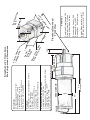
BladeRunner 23 Frame Servo
Motor & gearhead Dimensions
Gearhead:
Input (female) = .250 Output (Shaft) = .375 dia
Ratio : 10:1 reduction
RPM Max = 470 RPM
Torque Continuous = 450 oz-in
Torque Peak = 3200 oz-in
Radial backlash 10 Arc-minutes max
Servo Motor:
23 Frame flange mount 1/4” Shaft
Max RPM @ 60VDC = 4700
Continuous Torque = 50 oz-in
Continuous Current = 3.5A @ 50 oz-in
Peak Torque = 328 oz-in @ 20A
2.380"
R
EA
G
EA
H
Approx Steps per Inch with 1”
DP Pinion gear to rack = 3183
Encoder Line Count = 250
Pulses per Rev = 1000
Resolution = .0001 per step
Combined Overall length 10.5 “
Diameter (max) 2.5 inches
Weight (combined 5.4 lbs)
PHYSICAL
1
54 :1
0
D
3.
Inp
u
.25 t sha
ft s
0“
ize
2.4
0
Planetary Gearhead
Front View
2.
40
6
1.8
5
2.40”
ADDENDUM SERVO MOTOR SETUP AND TUNING
The BladeRunner Servo systems ship with 4 (or 5) servo motors and on the XY motors (3)
there are 10:1 gearheads. The following pages should be used to do the calculations for
the calibration and to determine the best velocity and acceleration. In addition to the
normal motor tuning in MACH the Gecko G320X drives have a PID set of pots that can be
used to do added response tuning of each motor. The PID settings are done during
final testing prior to shipping and seldom need to be adjusted. We have included
excerpts of the tuning process from Gecko but unless you are experiencing motion
induced fault issues, than doing adjustments just to see what it does will not “fix”
anything. While different loads can alter the response of the servo it will not effect the
accuracy. The servos are never at rest if they are powered up. As a result they WILL
make noise. If you attempt to tune them for no noise or minimum noise you will have a
“sloppy” system. Even a poorly tuned system will not allow a lot of error in position to
SERVO TUNING 101...Tuning by ear
If you don’t have a dual channel oscilloscope and the experience to use it, the easiest
way to tune a Gecko drive is by sound. The following covers that method and will yield
good results.
DO THIS ONLY IF YOU ARE CONFIDENT THAT THE MOTORS ARE EXHIBITING
SYMPTOMS OF IMPROPER TUNING! Most problems are mechanical (backlash,
loose gears/pulleys or settings in MACH) and cannot be helped with driver tuning)
This should be done ONLY if you experience any of the following:
1. Any motor that pulses slowly or is completely quiet qhen powered and not moving.
2. An axis that faults often when you are accelerating the motion
NOTE it is normal for a servo to fault and the ESPII to throw a fault when you do an
emergency STOP in MACH. The motor cannot stop instantly without causing a fault
Faults from other issues like overloads and noise cannot be fixed with motor
tuning!
The motors need to be mounted and under load to do tuning by ear.
1. Power up the motors. It may be easier to disconnect all but one motor and encoder
apir at a time so you can hear just that motor. if you accidently try to jog a motor that is
not connected the Gecko drive WILL fault.
2. Make sure the motor under test “locks”. If it starts to move than make sure the
encoder is plugged in for that motor. If the motor losses encoder pulses (either channel) it
will start to run away (spin at full speed huntting for a line on the encoder)
3. The motor should “hum”. The frequency is typically below 220 hz (octive 3 A on the
music scale). The important thing is that the motor does not sit and pulse indicating it is
way over dampened. The higher the frequency of the “hun” the tighter the tuning. There
are two main controls: The P and the D pots. The P is the gain and as you increase it the
hum frequency will go up.
CandCNC
Page
4. Start with the D pot turned all of the way counterclockwise (minumum) and slowly
advance the P pot until you either hit a point it gets unstable and the motor starts to
twitch (oscillate ) or you have it turned all of the way up. Make a note of the pot position
and back it off until the oscillation stops and then advance it to a position below that
point. Now increase the D (dampening) and listen to the frequency...it will drop. Stop
the D at about 1/4 turn and then advance the P past where it became unstable before. If
it starts to become unstable note the position and back it back down then advance the D
some
5. Start with the D and I pot turned all of the way counterclockwise (minumum) and
slowly advance the P pot until you either hit a point it gets unstable and the motor starts
to twitch (oscillate ) or you have it turned all of the way up. Make a note of the pot
position and back it off until the oscillation stops and then advance it to a position below
that point. Now increase the D (dampening) and listen to the frequency...it will drop.
Stop the D at about 1/4 turn and then advance the P past where it became unstable
before. If it starts to become unstable note the position and back it back down then
advance the D some more and turn the P back up. The objective is to have high gain
but with enough dampening to keep the loop stable under all conditions. Once you have
established the highest gain (P) that you can support at a given D then back it off a little
and leave the D where it is. Do not set the motor so that it is silent or pulses. After you
have the P and D set raise the I and that increases the dampening curve
Once you have the motor tuned in a static (non-moving setup) connect to load, than set
the tuning in MACH up to a high number (75 to 100) for acceleration and jog the motors
at full speed and change direction several times. If the motor driver faults that lower the
P slightly raise the dampening slightly by increasing the I setting. Once you have one
motor tuned correctly listen to the frequency of the sound. Use that as a guide to tune
the rest of the motors.
6. Setting the Torque Limit Trimpot. For 23 sized servo motors used on the
BladeRunner Servo system set the Torque Limit Trimpot to ½ range (centered between
full CW and CCW rotation. This limits current to 10A max. Leave Dip Switch 10 set to
OFF to prevent a 20A 1 sec peak cycle.
CandCNC
Page
Rotation Clockwise
(increase)
G320X Top View
P
I
D
Accessed
from rear
using small
flat blade
screwdriver
. Do NOT
force
Torque Limit
Trimpot
Dip Switch
Access with
Cover ON
SW1
Not used
SW2 Current or voltage mode select
ON – Current mode (default)
OFF – Voltage mode
SW3, SW4, SW5 Current mode servo gain
SW3 “ON”, SW4 “ON”, SW5 “ON” = Low gain (default)
SW3 “ON”, SW4 “OFF”, SW5 “ON” = Medium-low gain
SW3 “ON”, SW4 “ON”, SW5 “OFF” = Medium-high gain
SW3 “OFF”, SW4 “ON”, SW5 “ON” = High gain
SW6, SW7 Sets the G320X pulse multiplier
SW6 “ON” and SW7 “ON” = Step pulse times 1 (default)
SW6 “ON” and SW7 “OFF” = Step pulse times 2
SW6 “OFF” and SW7 “ON” = Step pulse times 5
SW6 “OFF” and SW7 “OFF” = Step pulse times 10
SW8, SW9 Sets the G320X following error limit
SW8 “ON” and SW9 “ON” = +/- 256 count following error limit (default)
SW8 “OFF” and SW9 “ON” = +/- 512 count following error limit
SW8 “ON” and SW9 “OFF” = +/- 1024 count following error limit
SW8 “OFF” and SW9 “OFF” = +/- 2048 count following error limit
SW10 Sets the G320X current limit trimpot behavior
CandCNC
Page
EXAMPLES
50 oz-in Servo motor @ 60 VDC with 10:1 gearhead and 1” dia pinion gear & direct
drive:
Max possible IPM = 4700rpm/10 X 3.142 = 1476 IPM.
* linear force = 100% servo motor continious torque X gear reduction / pinion Radius
= (50 Oz-in X 10) / .5 = 1000 linear oz of force
Same design but with 3:1 belt reduction from motor to pinion shaft:
* in the above calculations the motor RPM and torque numbers of 100% were used
since servo motor torque does not drop off with RPM. These are maximum numbers
and NOT recommended for normal cutting and rapids. High values of velocity and
acceleration put maximum stress on components for little benefit.
Calculating the beginning Steps per Unit on an SERVO AXIS
Use the following formula to get a ballpark steps per unit number in MACH
Psr = Pinion Speed increase ratio = Pitch Dia [in inches] X PI [3.1416]
Steps Per Rotation (SPR) of motor = encoder line count X 4; [250 line count =
1000]
Target Steps per Unit = (SPR X gearhead Reduction ratio/PSR)
1000 X 10 / 3.1416 = 3183.091 steps per inch
Once you have the calculated the number of steps it takes to move the axis one
inch then put that number into the STEPS per UNIT of the motor.
NOTE: IF you have the Step Multiplier on the Gecko set to 2X than you must divide
the Steps per Unit by 2
Based on the speed numbers you have calculated from the previous pages set you
velocity to a value of 50 to 80% of that number.
NOTE: MACH can only send the number of pulses per second as set in the Kernel
Speed in Ports&Pins. The number of pulses per second you need is the target
RPM (max) X the SPR/60. For a target RPM of 4000 and 250 line encoder you
need 40000000/60 = 66,666.0 steps per second (66 thousand) if your Kernel speed
is set to 45,000 (default) than you cannot achieve 4000 RPM. The step multiplier in
the G320X multiples the steps from the PC so a 2X setting makes the steps per
second required from the PC to be 33,333. The trade off is that it drops the
resolution by ½ as well.
Set your Beginning Acceleration to a low number like 10
CandCNC
Page
Calculating the max IPM you can travel (limited by max motor RPM )
4500 RPM = 75 RPS
Kernel Speed / SPR = RPS
45000/1000 = 45 RPS
Final Speed is limited by the smaller of the above two numbers
Pinion RPM = (RPS/ gearratio) X 60
IPM = Pinion RPM X Psr
For 45,000 and 250 line encoder:
(45000/1000) = 45 RPS
Pinion RPM = (RPS/10) X 60 = 4.5 X 60 = 270 RPM
IPM = 270 X 3.1416 = 848,23
RECOMMENDED SETTINGS FOR BladeRunner Dragon Cut
with 23 Frame servo motors and 10:1 Gearhead reductions
Recommened pinion DIAMETER : 1” (25mm)
Recommended belt reduction to pinion : NONE
Maximum belt reduction to pinion 2:1
Velocity XY and slave : 500 IPM (12700 mm/min)
Acceleration XY and Slave 35 to 50 IPS/sec **
Steps per unit XYA 3183.091 (1” pinion)
Velocity Z (5 turn Leadscrew) 300 IPM (7620 mm/min)
Acceleration Z : 20 IPS/Sec
Steps per unit Z = 1000 X leadscrew TPI
THC Rate (Mach setting) 20 **
Recommended Span Voltage (Cut Proffile) 4 to 8 **
Recommended plunge rate (SheetCAM) 50 - 100 IPM
Recommend DTHC Delay (SheetCAM or Cut Profile) 1.5 to 3 sec
** These settings may need to be adjusted depending on your mechanics to get smooth
cuts. Always adjust one parameter at a time.
CandCNC
Page 35