1
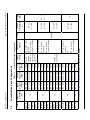
Chapter 3: Maintenance
3.4.2.3
BLC-10/20/25/40/50 User Manual
Problem: Low Output Voltage
Possible cause: Internal failure
Indications:
Power switch light - ON, POWER SUPPLY indication - OFF
Further checks and remedy:
Replace DC Power Inserter
3.4.2.4
Problem: Low or Zero Output Current
Possible cause: IFL cable disconnected or BUC failure
Indications:
POWER SUPPLY indication - ON
LOW CURRENT - ON
Further checks and remedy:
Check IFL cable for shorts
Check BUC
3.4.2.5
Problem: No IF Output Power or Low IF Output Power from the DC Power Inserter
Possible cause: High IF attenuation in the DC Power Inserter or wrong cable connections.
Indications:
System indicates missing or low uplink signal
Further checks and remedy:
Check cable connections
Using a screwdriver, gradually decrease the attenuation, using the ATT rotary switch and the
table below.
Position
Attenuation [dB]
0
0
1
2
Table 3-2:
DCA Attenuation Levels
2 3 4
5
6
7
8
9
A
4 6 8 10 12 14 16 18 20
Table 3-3:
B
22
C
24
D
26
E
28
F
30
IFL Cable Maximum Permitted Resistance
Model
DC Max. Power
Consumption (W)
Min. Input Voltage to
the BUC(V)
* Cable Max.
Resistance (#)
10 W
95
38
4
10 W 24V
95
18
1.3
20 W
170
38
2.2
25 W
210
38
1.8
40/50 W
380
38
* A summing of both center conductor and shielding resistance.
1.0
3-7