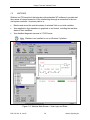
1
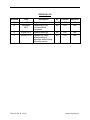
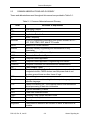
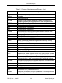
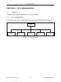
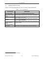
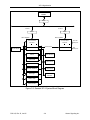
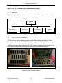
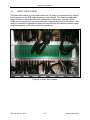
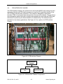
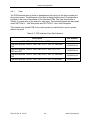
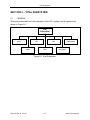
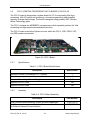
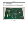
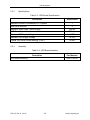
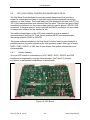
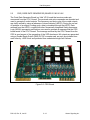
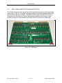
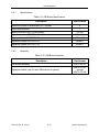
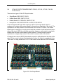
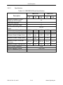
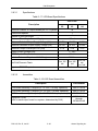
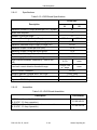
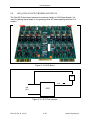
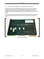
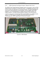
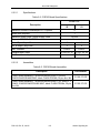
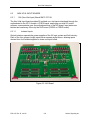
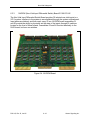
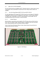
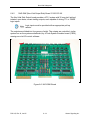
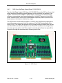
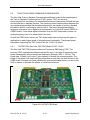
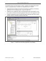
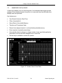
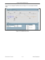
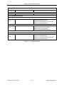
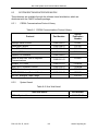
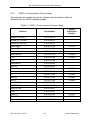
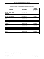
Chassis Configurations
4.4.1
Case
The PCB Interface case is similar in arrangement and options to the plug-coupled and
direct wired cases. The difference in this case is that an additional set of card guides is
installed on the rear of the chassis for the interface PCBs. The case descriptions in
Table 4–3 include a list of the boards in each case. The individual boards are discussed
under SECTION 5 – Vital Subsystem and SECTION 6 – Non-Vital Subsystem.
This chassis uses a fixed PCB for the main system bus and therefore a main system
cable is not used.
Table 4–3. PCB Interface Case Part Numbers
Description
Part Number
Case with split MB, VRD, IOB, CPU II, DI and DBO
31038-274-01
Case with split MB, CSEX3, VRD, IOB, CPU II, VSC, DI, DBO and
LDO
31038-274-02
Case with split MB, CSEX3, VRD, IOB, CPU II, VSC, FSVT, DI,
DBO and LDO
31038-274-03
Case with split MB, CSEX3, VRD, IOB, CPU II, VSC, DI, DBO and
LDO
31038-274-04
Case with split MB, CSEX3, VRD, IOB, CPU II, VSC, DI and DBO
31038-274-05
P2511G, Rev. D, Jan/15
4–8
Alstom Signaling Inc.