1
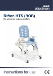
Z110, Z120, Z130
Rifton HTS Hygiene Toileting System
Z110, Z120 & Z130 Product Manual
®
Contents
Safety messages
3
Recommended use
4
Item dimensions
5
Check your order
6
Basic components
6-8
Bases
8-9
Footboard
10
Mounting bars
11
Accessories
2
Seat & back pads, headrest
12
Butterfly harness
13
Anterior support / tray
14
Lateral supports, chest strap
15
Hip guides, pan and bowl adapter
16
Deflectors and abductor
17
Calfrest and ankle straps
18
Footboard for mounting bar, tub base
19
Portability base
20
Operation
21
Maintenance, cleaning and warranty
22
Materials and user modifications
23
© 2014 Rifton Equipment
WARNING
• Thoroughly read and understand the information in this product manual before
attempting to use this product. If the procedures and instructions in this product manual
are not followed, serious injury or death could occur.
• A qualified professional must assess the appropriateness and safety of all equipment for
each user.
• This product is intended for use by clients of unreliable judgment. Adult supervision is
required at all times.
• To prevent falls and injuries:
○ Do not use this product on rough and uneven terrain, around swimming pools, or
near stairways.
○ Ensure the appropriate use of straps and supports at all times. Straps and supports
are provided for the safety of the user and must be carefully adjusted for comfort and
security.
○ Tighten all adjustment knobs before use and immediately after making any
adjustments.
• To prevent falls, strangulation, head entrapment or other injuries:
○ Always use seatbelt when the tray, chest strap or headrest are in use.
○ Tighten the seatbelt portion of the butterfly harness before tightening the upper straps.
• The portable base is intended for travel use only and should not be used as the primary
base. Ensure adequate stability when using the portable base.
• Do not use this product for clients outside the height and weight limits specified in this
manual.
• To prevent structural failure, which may result in serious injury or death:
○ Inspect this product and accessories regularly for loose or missing screws, metal
fatigue, cracks, broken welds, missing attachments, general instability or other signs
of excessive wear.
○ Immediately remove this product from use when any condition develops that might
make operation unsafe.
○ Do not use Rifton components or products for any purpose other than their intended
use.
○ Replace or repair components or products that are damaged or appear to be
unstable.
○ Use only Rifton authorized replacement parts.
3
Key for users
Use this key to determine which sections of this product manual apply to
you.
Technical Users For professionals who order and set up Rifton
products.
Home Users For care-givers who use Rifton products on a regular
basis.
Maintenance Personnel For anyone who is responsible for
service or re-ordering of Rifton products and parts.
IMPORTANT
Please save this product manual for future reference. Additional copies are
available at www.rifton.com
Recommended use
The Rifton HTS is a Class 1 medical device. The intended use of the HTS is to compensate
for disease, injury, or disability by allowing comfortable toileting and showering, and by
providing modification for anatomical positioning.
The many different configuration options of the HTS provide great versatility; it can be
used as a stand-alone commode, over the toilet, mounted directly on the toilet, in a roll-in
shower, or for a tub shower. Optional supports and accessories allow the HTS to be used
for clients with a wide range of needs and disabilities.
4
User and item dimensions
User dimensions - inches (cm)
Height
Z110 small
Z120 medium
Z130 large
30-46 (76-117)
42-56 (106-142)
50-74 (127-188)
Key user dimension: height
The user’s overall height is a general guide to help you select the appropriate size of HTS.
Choose the model that allows for growth.
Important: Make sure that seat width, depth and height are adequate for each individual user, and
that the user’s weight does not exceed the maximum weight recommended.
Item dimensions – inches (cm)
Overall width
Seat (front) to footboard height*
Small
Medium
Large
21¼ (54)
21¼ (54)
23½ (60)
8-13 (20-33)
10-15 (25-38)
13-18 (33-46)
Seat (front) to floor; mobile tilt frame
15-21½ (38-55)
15-21½ (38-55)
17-22½ (43-57)
Seat (front) to floor; mobile non-tilt frame
15½-20 (39-51)
15½-20 (39-51)
18-22 (46-56)
Seat (front) to floor;
stationary non-tilt frame
12½-17 (32-43)
12½-17 (32-43)
15-19 (38-48)
Seat depth
8/9/10/11
(20/23/25/28)
11½/12½/13½/14½
(29/32/34/37)
14½/15½/16½/17½
(37/39/42/44)
Seat width
13/15/17 (33/38/43)
8/10/12 (20/25/30)
10/12/14 (25/30/36)
Armrest height
5¾ (14.5)
7 (18)
8¾ (22)
Backrest height above seat
16½ (42)
19½ (50)
24½ (62)
Backrest width
11½ (29)
13½ (34)
16 (41)
Tilt in space FORWARD
15°
15°
15°
Tilt in space BACK
15°
15°
15°
6° fwd,
6° and18° back
6° fwd,
6° and18° back
6° fwd,
6° and18° back
Max. clear height under seat (tilt frame)
19 (48)
19 (48)
20 (51)
Max. clear height under seat
(stationary non-tilt frame)
15 (38)
15 (38)
16½ (42)
Max. clear height under seat
(mobile non-tilt frame)
18 (46)
18 (46)
19½ (50)
18½ (47)
18½ (47)
N/A
75 (34)
150 (68)
**250 (113)
Backrest angle adjustment
Portability base clearance
(fits over ADA compliant toilets)
Max. working load - lbs (kg)
* When mobile base is in lowest positions and footboard is fully extended, it may prevent front casters from swiveling.
In this case, either change footboard angle or raise seat height to give casters room to swivel.
** The maximum working load for the large HTS footboard is 150 lbs (68 kg).
5
Check your order
Your Rifton HTS has been shipped according to your specifications. It will require some
tool-free assembly. Follow these instructions to ensure that your product is assembled
and used correctly. This product manual is comprehensive, and may discuss features not
included in your configuration of the HTS.
If your shipment is incomplete or in any way damaged on
arrival, please call Customer Service, 800.571.8198.
Basic components
A Quick Reference Guide for the HTS can be dowloaded from a QR code on
the back of the backrest.
Tip: Every blue lever or button
indicates a point of adjustment.
Seat depth
The side pieces allow for seat depth
adjustment. Lift the blue latches on both
outer sides (see figure 6a), move both sides
together to the desired seat depth and find
a latched position.
Seat depth latch
Figure 6a
This same adjustment will also enable both
sides to slide off the seat towards the front
for cleaning the area underneath.
Backrest angle
The backrest angle can be adjusted 6°
forward, 6° back, and 18° back (see figure
6b). Raise both back angle triggers, adjust
to desired angle and release into a latched
position (see figure 6c).
Backrest
removal
Figure 6b
+6° -6° -18°
Back angle trigger
Figure 6c
6
Backrest installation
or removal
Angle triggers
To install the backrest: Tip the backrest
toward the front (see figure 7a). Insert the
bottom end of the backrest between the
latch plates while raising the backrest angle
triggers. Firmly press down on the backrest
while rotating it back towards the first
latched position.
To remove the backrest, adjust the back
angle all the way forward. Then lift the
backrest up.
Latch
plates
Figure 7a
Seatbelt
To prevent falls,
strangulation, head
entrapment or other injuries, always use
seatbelt when the tray, chest strap or
headrest are in use.
WARNING
Every HTS is provided with a seatbelt.
To attach the seatbelt insert the seatbelt
attachment clip (see figure 7b) into the
socket at the back end of the side piece.
Check to ensure that the seatbelt latches
into place.
Clip
Figure 7b
For users that tend to slide forward on
the seat, you may benefit from threading
the seat belt to the inside of the backrest
supports (see figure 7c).
On the small HTS there is an additional
option for seat belt threading to ensure a
more secure positioning for small active
users. Thread the seat belt through the
hooks provided at the bottom back edge of
the seat (see figure 7d).
Figure 7c
Figure 7d
7
Armrests
To attach the armrest, insert the bottom of
the armrest into the oval slots in the side
pieces and press down firmly until it latches
into place (see figure 7c).
A
To remove the armrest, squeeze the release
button (A) and pull the armrest up.
Tip: Armrests of different sizes can
be retrofitted.
Figure 7c
Bases
To prevent falls and
injuries, always make
sure both seat hooks are inserted into the
base sockets and that both seat latches
are latched to base.
WARNING
Attaching the seat
Insert both hooks at the rear of the seat
into the sockets of the frame (see figure
8a). Then push front of seat down onto
frame until the latches audibly engage.
Hooks into
socket
Figure 8a
Removing the seat
To remove the seat from a base, pull both
seat latches under the front edge of the
seat (see figure 8b) and lift it from the
base.
Seat latches
Figure 8b
8
Base height adjustment
To prevent falls and
injury, do not adjust
height with user in the product.
WARNING
To lower the seat, squeeze both height
latches on the frame uprights (see figure
9a) while supporting the weight of the
seat. Lower both sides evenly to prevent
binding.
To raise the seat, flip up the footboard, put
one foot on the frame cross bar, and pull
up on the seat frame (there is no need to
release the height latches).
Height
latches
Figure 9a
Tilt-in-space adjustment
Tip: If adjustment feels tight, then
try with the tilt-in-space all the way
forward or back.
The tilt-in-space adjustment is available
on the Z122 and Z132 bases. Use the tilt
trigger at the right rear of the seat (see
figure 9b) to release the two locking gas
springs. Tilt adjusts 15° forward and 15°
back. It is easy to tilt the HTS with the user
in the product.
Tilt trigger
Figure 9b
Casters and stationary feet
The casters and stationary rubber feet can
easily be replaced or exchanged. Simply
pull the caster stem or rubber foot out of
the end cap (see figure 9c). Ensure that
replacement casters or feet are inserted to
their full depth.
Figure 9c
Caster brakes
To apply the brake, step down on the brake
lever. To release the brake, raise the lever
(see figure 9d).
Brake lever
Figure 9d
9
Footboard
CAUTION
To prevent falls,
tipping or other injury:
Height
buttons
• Do not exceed 150 pounds on
the footboard.
• Do not stand on footboard while it is
angled forward.
• Do not place maximum load at front
edge of footboard.
The footboard is included with
mobile bases.
Figure 10a
Angle
triggers
Height adjustment
To adjust footboard height, press both
height buttons, moving the footboard to
the desired height, then release the buttons
at a latched position (see figure 10a).
Footboard angle adjustment
The angle of the footboard can be adjusted
by pushing up on both angle triggers while
moving the footboard to the desired angle
(see figure 10b).
Figure 10b
Footboard can be folded up out of the way
for floor-level transfers (see figure 10c).
Figure 10c
10
Mounting bars
To prevent falls or
injuries, ensure that
the toilet is securely attached to the
floor and that the seat bolts are in good
condition before attaching the mounting
bar. Inspect the toilet stability and seat
bolts at regular intervals while the
mounting bar is in use.
WARNING
There are two kinds of mounting bars, to fit
either standard round, or elongated toilets
(see figure 11a).
Elongated
Standard
Figure 11a
The mounting bar attaches with the bolts
that hold the seat, and provides a firm
attachment point for the seat and back
units (see figure 11b).
To determine which type of mounting bar
you need, measure from the centerline
of the seat bolts to the front edge of the
porcelain bowl. Use a standard toilet
mounting bar if this is 17”(43 cm) or
less, otherwise use the elongated toilet
mounting bar.
Attachment of seat to
mounting bar
To prevent falls or
injuries, ensure that
both hooks are fully engaged in the
sockets of the mounting bar before using
the HTS.
Figure 11b
WARNING
To attach the seat to the mounting bar,
move the backrest out of the way by tilting
or sliding it forward, then insert both
hooks on the seat into the sockets on the
mounting bar and lower the seat onto the
toilet bowl (see figure 11c).
Hooks
Figure 11c
11
Accessories
Seat and back pads
The seat and back pads are removable for
cleaning. They are made of Polyurethane with a
durable integral skin.
There are two styles of seat pad. One has
a wider opening which opens to the rear
facilitating hygiene care (see figure 12a). The
second one has a narrower opening, which is
closed at the back and provides more support
for the user (see figure 12b).
Figure 12a
The seat and back pads attach with four snaps
that snap into the holes in the seat and backrest
(see figure 12c).
Figure 12b
Hole
Headrest
To prevent head
entrapment or injury,
always use seatbelt while the headrest
is in use.
WARNING
To attach and adjust headrest height,
push height button (A). Insert the stem of
headrest into the headrest slot (see figure
12d) to desired height. Release the button
and adjust height until the latch audibly
engages.
Figure 12c
To adjust depth and angle of headrest,
loosen oval knobs (B), adjust to the desired
position and retighten the knobs.
B
A
Figure 12d
12
Snap
Butterfly harness
WARNING
To prevent falls,
strangulation or
other injuries:
• Tighten the seatbelt portion of the
butterfly harness before tightening the
upper straps.
• Check fit of harness after every
adjustment.
To attach the butterfly harness, remove the
center section of the seatbelt (A). Replace it
with the butterfly harness (B), which has a
built-in seatbelt (see figure 13a).
B
A
Figure 13a
Adjust the seatbelt tension, then clip the
shoulder straps to the sockets on the
backrest (see figure 13b).
For small users, you may wish to attach the
shoulder straps through the upper slot in
the backrest (see figure 13c).
Figure 13b
Figure 13c
13
Anterior support/tray
To prevent falls,
strangulation or other
injuries, always use a seatbelt when the
tray is in use.
WARNING
The anterior support has a padded surface
for the user to lean against, which provides
an excellent, forward-leaning, toileting
position with trunk and arms supported by
the tray (see figure 14a).
To adjust tray depth, squeeze latch under
the front of tray (see figure 14b).
Figure 14a
Latch
Figure 14b
14
Lateral supports
A
Lateral supports are available with or
without a chest strap for secure upper
trunk positioning. They may be adjusted
separately, in height, angle and width using
the knob (B) behind the backrest.
To attach and/or adjust lateral support
(A), loosen knob (B) and insert the key
(C) into extrusion (D) at the rear of the
backrest. Adjust height, angle and width
of lateral support to fit client by sliding it
up and down, sliding bracket (E) along its
slot and by rotating bracket (E) around the
knob. When desired adjustment is reached,
tighten knob firmly (see Figure 15a).
D
C
B E
Figure 15a
Chest strap
WARNING
To prevent falls,
strangulation or
other injuries:
• Always use seatbelt when the chest
strap is in use.
• Always ensure that chest strap is
correctly adjusted.
The chest strap threads onto the lateral
supports as shown (see figure 15b). The
chest strap should thread to the inside of
the lateral supports (see figure 15c).
Figure 15b
Figure 15c
15
Hip guides
The seat width may be adjusted with a pair
of hip guides that attach onto the armrests.
In the first position they reduce the seat
width by 2” (5 cm), and in the second
position they reduce it by 4”(10 cm) (see
figure 16a).
Slide the hip guide onto the armrest with
the notch in the hip guide up and back.
Insert the armrest into the armrest slot
through the hip guide.
Notch at back
Figure 16a
Pan
The pan (see figure 16b) enables the HTS to
be used as a stand-alone commode. Insert
the pan into the tracks under the seat, from
the back of the chair. Push until it latches
into place. Remove it by pulling straight
back (see figure 16c).
Bowl adapter
Figure 16b
The bowl adapter (see figure 16d)
accommodates situations where the hole
in the HTS isn’t fully over the hole in the
toilet. It is inserted at the front edge of the
hole, under the seat pad. A seat pad must
be used in conjunction with the
bowl adapter.
Figure 16c
Figure 16d
16
Deflectors
The standard deflector inserts into the
slot on the seat pad with the hollow cup of
the deflector toward the user
(see figure 17a).
Tip: Adding the abductor to the
standard deflector provides stability to
the deflector (see figure 17c).
Ribs in seat pad
Figure 17a standard deflector
The splash guard provides even more
coverage. It is held against the user with
the seatbelt or butterfly harness (see figure
17b).
Abductor
The padded abductor inserts into the slot
at the front edge of the seat. It can be
removed by squeezing the blue latch (A)
and pulling the abductor out (see figure
17c).
Figure 17b splash guard
To minimize risk of
infectious disease
transmission, the HTS should be cleaned
and disinfected between uses by
different patients. Inadequate cleaning
and disinfecting of equipment may
increase the risk of cross contamination.
CAUTION
Remove the Polyurethane pads for cleaning
with soapy water or a mild disinfectant.
A
Figure 17c
17
Calfrest
This option requires the use of
a footboard.
The calfrest attaches above the footboard
(see figure 18a). It should be removed if the
footboard is in the top positions.
The calfrest attaches to the footboard
uprights. With the webbing at the back,
and rounded corners down, loop the
webbing around the uprights and thread
webbing through the metal ring at the
front, engaging the hook and loop snugly
around uprights (see figure 18b).
Ankle straps
Figure 18a
Figure 18b
This option requires the use of
a footboard.
To attach the ankle straps:
1. Insert the webbing tab into the
horizontal slot at the back of the
footboard, (see figure 18c).
2. Turn the webbing to slide it into the
vertical slot and pull to engage it (see
figure 18d).
Figure 18c
3. Adjust the straps to fit the user’s needs.
The straps with hook
and loop closures may be
laundered at 160F (70C) or less. Engage
the closures before washing. Do not iron.
NOTICE
Figure 18d
18
Footboard for mounting
bar attachment
WARNING
To prevent falls or
other injury:
• Ensure that the square metal tubing
attaching the footboard to the seat
rests on the front edge of the toilet.
• Do not stand on footboard for
mounting bar attachment.
Figure 19a
A
To attach a footboard to the HTS when
used on the toilet with a mounting bar (see
figure 19a):
1. Turn the HTS seat upside down (see
figure 19b).
2. Insert the small metal tabs at the end of
metal tubing on footboard (A), into slots
at the back of the seat.
B
Figure 19b
3. Push footboard down firmly to latch
square tubing onto blue latches (B).
4. Attach HTS to mounting bar
(see page 11).
The other adjustments for the footboard
are the same as described on page 10.
Tub base
To prevent falls and
injuries, always make
sure both seat hooks are inserted into the
base sockets and that both seat latches
are latched to base.
WARNING
Figure 19c
The tub base is for use in a bathtub to
bathe or shower the client (see figure 19c).
Attaching the seat
Insert both hooks at the rear of the seat
into the sockets of the tub base frame
(see figure 19d). Then push front of seat
down onto frame until the latches audibly
engage.
Hooks into
socket
Figure 19d
19
Portability base with
carry-bag
WARNING
To prevent falls and
injuries:
• The portable base is intended for
travel use only and should not be used
as the primary base. Ensure adequate
stability when using the portable base.
• Check that the two pieces of the frame
are fully engaged before attaching the
seat.
Figure 20a
• Always make sure both seat hooks
are inserted into the base sockets and
that both seat latches at the front are
latched to base.
The portability base is a light-weight,
foldable frame with a carry-bag (see figure
20a). This base fits in the back pouch of
the carry-bag.
The seat, back, armrests and other
accessories can go into the front pouch of
the carry-bag (see figure 20b).
To assemble the base, unfold both halves
of the frame, insert the square peg of
one half into the square tube of the other
half of the frame (see figure 20c). Make
sure the two pieces of the frame are fully
engaged before attaching the seat.
Figure 20b
Figure 20c
Then attach the seat to the frame (see
figure 20d) as described on previous page
(see figure 19d).
Figure 20d
20
Operation
The Rifton HTS has two main
functions; toileting and showering.
For toileting, the ideal position often
incorporates forward-leaning of the
trunk and a closed hip angle. This can
be achieved with the HTS by angling the
backrest slightly forward, adjusting the seat
to level or slightly back, using the anterior
support to provide support at the trunk and
arms, and raising the footboard so that feet
are well supported (see figure 21a).
For showering, raise the height adjustment
and tilt the frame back. With the backrest
reclined and the footboard extended, a
restful reclined position can be achieved
for showering and hair washing (see figure
21b). The caregiver should adjust the
positioning to fit the unique needs of each
client.
Figure 21a
Figure 21b
21
Maintenance
This product is designed and tested for an expected life of 5 years when used and
maintained in accordance with this manual. At all times, users must ensure that the
product remains in a safe and useable condition, including regular maintenance and
inspections as specified in the manual.
To prevent structural failure, which may result in serious injury or death:
• Inspect this product and accessories regularly for loose or missing screws, metal
fatigue, cracks, broken welds, missing attachments, general instability or other signs of
excessive wear.
• Immediately remove this product from use when any condition develops that might
make operation unsafe.
• Do not use Rifton components or products for any purpose other than their intended
use.
• Replace or repair components or products that are damaged or appear to be unstable.
• Use only Rifton authorized replacement parts. Order information for replacement parts
is provided on the back of this product manual.
Cleaning
After each use, clean with disinfectant wipes or a solution of up to 10% bleach.
The straps with hook and loop closures may be laundered. Engage the closures before
washing. Do not iron.
The Polyurethane pads are easy to remove to allow cleaning and drying underneath. They
can be wiped clean with soapy water or a mild disinfectant.
Warranty Statement
If a Rifton product breaks or fails in service during the first year, we will replace it
free of charge.
22
Materials
• Steel hardware items (nuts, bolts, screws, etc) are stainless steel.
• Upholstery items (pads, support blocks, padded prompts, etc) are waterproof
Polyurethane integral skin foam.
• The frame is aluminum and stainless steel, coated with a baked-on paint finish.
• Straps are made of polypropylene webbing with quick-drying Spacer Mesh fabric
for padding.
• Plastic components are injection-molded from a variety of industrial resins.
All materials are latex, lead and phthalates free.
User modifications
To prevent serious injury or death, do not modify or alter Rifton
products or components, or use Rifton products or components
in conjunction with products from other manufacturers. Rifton does not accept
responsibility for any modifications or alterations made to our components or products
after they leave our premises. Customers modifying or altering our components or
products, or using them in conjunction with products from other manufacturers, do so
at their own risk.
WARNING
23
Rifton Contact Information
@
Email
Phone
[email protected]
800.571.8198
9–5 EST
Mail
Fax
Rifton Equipment
PO Box 260
Rifton NY 12471– 0260
800.865.4674
Online
www.Rifton.com
To order replacement parts
1. Locate the ID number of the product on the small white label.
2. Have this number available when you call 800.571.8198 for your
customer service representative.
We are glad to supply replacement parts. Although Rifton makes every
effort to supply correct parts and instructions for repairing or refurbishing
your equipment, you are responsible to make sure that the repairs or
modifications are correctly and safely completed.
Find letters of medical necessity
and informative articles at:
www.rifton.com/HTS
24
ND41 ECO N/A Revision D
Use only replacement parts supplied by Rifton Equipment.