1
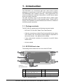
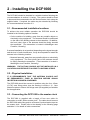
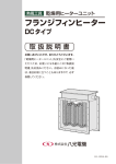
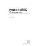
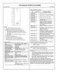
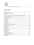
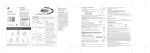
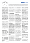
DCF1000
DCF Radio Time Code Receiver
User Manual
Version 1.2
Copyright
Software Licence
© 2011 - 2015 World Time Solutions Limited. All Rights Reserved.
All information contained within this document is the property of
World Time Solutions Limited and cannot be used or reproduced
by any person or company without written consent from World
Time Solutions Limited.
World Time Solutions Limited reserves the right to make periodic
amendments to the information in this document without notice.
Trademarks
All registered trademarks and trademarks are property of their
respective owners.
RoHS Compliance
World Time Solutions Limited works with its suppliers to ensure
all products comply with the Restriction of Hazardous Substances
(RoHS) directive.
For further information, please visit our web site at:
www.worldtimesolutions.com/rohs.html
Disposal
This product contains proprietary World Time Solutions Limited
software. This software is supplied under the World Time
Solutions Limited Software Licence Agreement.
For further information or to view a copy of the software licence,
please visit:
www.worldtimesolutions.com
Limited Warranty
The DCF1000 DCF Radio Time Code Receiver is guaranteed
against failure due to faulty parts or workmanship for a period of
five (5) years from date of purchase.
In the event of product failure due to faulty parts or workmanship
within the warranty period, World Time Solutions Limited, at
its own discretion, will either (a) repair the product, (b) supply
a replacement product, (c) supply a functionally equivalent
replacement product, or (d) refund the purchase price of the
product.
The limited warranty will not apply if (a) the product has not been
installed or operated as per our instructions, (b) the product has
been modified in anyway.
In the event of failure, the DCF1000 should be returned to the
manufacturer for inspection and repair. Please visit our support
pages for further details:
www.worldtimesolutions.com/support.html
Technical Support
Please dispose of this unit properly. To minimize pollution and
help protect the environment, this unit should be recycled.
For further information and/or to view a copy of the World Time
Solutions Limited Waste Electrical and Electronic Equipment
Policy, please visit our web site at:
To obtain help with the installation or operation of the DCF1000,
please visit our web site at:
www.worldtimesolutions.com/support.html
www.worldtimesolutions.com/recycle.html
II
DCF1000 - DCF Radio Time Code Receiver - User Manual - Version 1.2
1 - Introduction
The DCF1000 is an economical radio time code receiver system
designed to synchronise to the DCF radio transmission broadcast
from Mainflingen near Frankfurt, Germany. Once synchronised, the
receiver provides time and date information to an MC Series master
clock via a cable connection.
The wide sensitivity range of the DCF1000 allows reliable signal
decoding towards the limits of the broadcast range. Please refer to
section 2 for installation recommendations and section 3 for details of
confirming system operation.
1.1 - Package contents
The DCF1000 is supplied with the following component parts:
• DCF1000 77.5 kHz DCF Radio Time Code Receiver
• Cable for connection to a World Time Solutions MC Series master
clock (Please note: The length of cable supplied is dependent on
the model ordered. See appendix A for details)
• 5 way socket block connector for connection to an MC Series
master clock
• A4 user manual
1.2 - DCF1000 front view
The drawing below shows the front view of the DCF1000.
1
4
DCF1000
77.5 kHz DCF Radio Time Receiver
Power
Lock
Data
2
Fault
A B
3
World Time
Solutions
C D
5
www.worldtimesolutions.com
Figure 1.1
DCF1000 front view
6
No.
Function
No.
1
IP66 (NMEA 4X) polycarbonate
enclosure with clear cover
4
Function
Cover fixings (x4)
2
Status LEDs
5
Case fixing points (x4)
3
Cable connection point
6
Cable entry grommet
Table 1.1 - DCF1000 functions
DCF1000 - DCF Radio Time Code Receiver - User Manual - Version 1.2
1
2 - Installing the DCF1000
The DCF1000 should be installed in a suitable location following the
recommendations in section 2.1 below. The system should be fixed
in place and then connected to the MC Series master clock using the
supplied cable. If required, the cable may be extended by following
the recommendations in section 2.3.
2.1 - Recommended installation locations
To achieve the most reliable operation the DCF1000 should be
installed in the following optimum location:
• On the outside of a building, away from any metallic objects or
electrically noisy equipment. The antenna should be positioned
on the side of the building closest to the transmitter. In addition,
the front (clear) face of the antenna should be facing towards
the transmitter. (The transmitter is located in Mainflingen near
Frankfurt, Germany).
If external installation is not practical, depending on the signal strength
and the level of radio interference, it may be acceptable to install the
antenna in the following location:
• Mounted internally, away from any metallic objects or electrically
noisy equipment. The front (clear) face of the antenna should
be facing towards the transmitter. (The transmitter is located in
Mainflingen near Frankfurt, Germany).
Warning: The DCF1000 should not be installed in a
location susceptible to a direct lightning strike.
2.2 - Physical installation
It is recommended that the antenna should not
be permanently fixed in position before signal
reception has been confirmed.
The DCF1000 should be secured in position using the four 4.5mm
(0.178”) case fixing points (see the drawing in section 1.2). Care
should be taken to ensure the fixings used (not supplied) are suitable
for the application.
2.3 - Connecting the DCF1000 to the master clock
The DCF1000 is supplied with a length of four core cable for
connection to an MC Series master clock. The cable should connect
the DCF1000 cable fixing point to a Remote Synchronisation Input on
the master clock. Please refer to the drawing on the following page
and table 2.1 for details of cable connections.
2
DCF1000 - DCF Radio Time Code Receiver - User Manual - Version 1.2
Section 2: Installing the DCF1000
DCF1000
77.5 kHz DCF Radio Time Receiver
Power
Lock
Data
Fault
A B
World Time
Solutions
C D
REMOTE SYNCHRONISATION INPUTS
SYNC 1
SYNC 2
A B C D
A B C D
www.worldtimesolutions.com
Figure 2.1 - DCF1000 master clock connection
Terminal ID
GND
Cable colour code
Cable screen drain wire
A
Black / Red
B
Red
C
Black / White
D
White
Table 2.1 - Cable connection detail
If required, the cable may be extended using Belden 9502 type cable
up to a maximum total length of 150m (500ft). For low smoke/plenum
applications, the supplied cable should be substituted for a Belden
82502 (or equivalent) type cable.
DCF1000 - DCF Radio Time Code Receiver - User Manual - Version 1.2
3
3 - System operation
Following installation (see section 2) and upon powering the MC Series
master clock, the DCF1000 will automatically attempt to synchronise
to the DCF radio signal. The DCF1000 also begins to send setup
information to the master clock.
Depending on signal strength and the level of radio interference,
system lock may take up to 30 minutes. Once the DCF1000 has
synchronised to the DCF radio transmission, time and date information
is automatically sent to the master clock.
3.1 - DCF1000 status information
The operational status of the DCF1000 may be visually confirmed via
the status LEDs (see figure 1.1). The table below lists the function of
the different LEDs.
LED
Status
Power
Green LED illuminates continuously when power is applied
to the DCF1000 and the system is running
Lock
Green LED illuminates continuously when the DCF1000 is
synchronised to the DCF transmission
Data
Green LED flashes to indicate DCF data being received
Fault
Red LED illuminates if no radio data is detected for a
prolonged period
Table 3.1 - Status LEDs
The synchronisation status may also be confirmed via the MC Series
master clock. Please refer to the user manual supplied with the
master clock for further details.
3.2 - Improving signal reception
The radio detection circuit in the DCF1000 radio time code receiver is
highly directional in its ability to decode the DCF signals. To enable
the best reception of the DCF signal, the installer should ensure
that the decoder circuit is properly aligned with the DCF transmitter
(located in Mainflingen near Frankfurt, Germany).
Alignment may be confirmed by slowly rotating the DCF1000 and
observing the operation of the ‘Data’ LED. When correctly aligned,
the ‘Data’ LED should flash once per second.
4
DCF1000 - DCF Radio Time Code Receiver - User Manual - Version 1.2
A - Specifications
Typical Performance Specifications:
PPS accuracy:
40 msec
I/O Connections:
I/O connection:
Single 1000 Series communication port for
connection to a MC Series master clock
Mechanical & Electrical Specifications:
Dimensions:
202 x 80 x 55 mm (7.95” x 3.15” x 2.17”)
(including removable wall brackets,
excluding cable grommet)
Weight:
0.5 kg (excluding cable)
Enclosure:
IP66 / NEMA 4X rated, UV stabilised
polycarbonate enclosure. Light grey body
and clear cover.
Cable:
Two pair plus drain 7x32 (24 AWG)
stranded cable with 100% foil shield and
semi-rigid, sunlight resistant, Polyvinyl
Chloride (PVC) jacket.
Cable length supplied:
DCF1000-05: 5m (15ft)
DCF1000-15: 15m (50ft)
DCF1000-50: 50m (150ft)
Environmental Specifications:
Operating temperature:
-20 to +50 ºC
Relative humidity:
0% - 95%, noncondensing
Standards Compliance:
Electrical Safety:
BS EN 60950-1:2006
Radio Disturbance:
BS EN 55022:2006
Immunity Characteristics:
BS EN 55024:2003
DCF1000 - DCF Radio Time Code Receiver - User Manual - Version 1.2
5
World Time Solutions Limited
1st Floor, Barclays House, Gatehouse Way, Aylesbury, Buckinghamshire, HP19 8DB, United Kingdom
+44 (0) 1296 331428 - [email protected]
www.worldtimesolutions.com