1
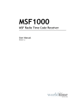
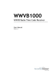
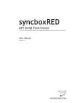
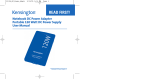
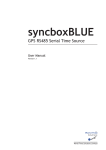
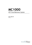
GPS4000
GPS Time Receiver System
User Manual
Version 1.1
World Time
Solutions
World Time Solutions Limited
COPYRIGHT
SOFTWARE LICENCE
© 2011 - 2014 World Time Solutions Limited. All Rights Reserved.
All information contained within this document is the property of
World Time Solutions Limited and cannot be used or reproduced
by any person or company without written consent from World
Time Solutions Limited.
World Time Solutions Limited reserves the right to make periodic
amendments to the information in this document without notice.
TRADEMARKS
All registered trademarks and trademarks are property of their
respective owners.
RoHS COMPLIANCE
World Time Solutions Limited works with its suppliers to ensure
all products comply with the Restriction of Hazardous Substances
(RoHS) directive.
For further information, please visit our web site at:
www.worldtimesolutions.com/rohs.html
DISPOSAL
This product contains proprietary World Time Solutions Limited
software. This software is supplied under the World Time
Solutions Limited Software Licence Agreement.
For further information or to view a copy of the software licence,
please visit:
www.worldtimesolutions.com
LIMITED WARRANTY
The GPS4000 GPS Time Receiver System is guaranteed against
failure due to faulty parts or workmanship for a period of five (5)
years from date of purchase.
In the event of product failure due to faulty parts or workmanship
within the warranty period, World Time Solutions Limited, at
its own discretion, will either (a) repair the product, (b) supply
a replacement product, (c) supply a functionally equivalent
replacement product, or (d) refund the purchase price of the
product.
The limited warranty will not apply if (a) the product has not been
installed or operated as per our instructions, (b) the product has
been modified in anyway.
In the event of failure, the GPS4000 should be returned to the
manufacturer for inspection and repair. Please visit our support
pages for further details:
www.worldtimesolutions.com/support.html
TECHNICAL SUPPORT
Please dispose of this unit properly. To minimize pollution and
help protect the environment, this unit should be recycled.
For further information and/or to view a copy of the World Time
Solutions Limited Waste Electrical and Electronic Equipment
Policy, please visit our web site at:
To obtain help with the installation or operation of the GPS4000,
please visit our web site at:
www.worldtimesolutions.com/support.html
www.worldtimesolutions.com/recycle.html
II
GPS4000 - GPS Time Receiver System - User Manual - Version 1.1
1 - Introduction
The GPS4000 is a high precision time receiver system comprising of
a GPS timing antenna and separate decoder module. The system is
designed to synchronise to the GPS navigation network and provide
time information to an MC Series master clock via a cable connection.
The GPS4000 incorporates advanced anti-jam technology, reducing
the effects of interference in hostile RF environments. Cable delay
compensation ensures timing accuracy is not degraded when using
long lengths of cable. Please refer to section 2 for installation
recommendations and section 3 for details of system operation.
1.1 - Package contents
The GPS4000 is supplied with the following component parts:
• GPS timing antenna
• Decoder module
• Stainless steel surface (or wall if ordered ) mount antenna bracket
• 8m TNC to TNC RG58CU antenna connection cable
• Cable for connection to an MC Series master clock (Cable length
is dependent on the model ordered. See appendix A for details)
• 5 way connector for connection to an MC Series master clock
• A4 user manual
1.2 - GPS4000 front view
8
Cable Delay Compensation
(cable lengths in metres)
10
8
4
2
1
GPS Time Receiver System
Power
80
40
20
10
8
4
2
1
GPS4000
1
Output Cable
Input Cable
5
Lock
2
Data
Antenna
Fault
World Time
Solutions
WARNING:
Ensure Antenna is connected
before applying system power
3
A B
6
C D
www.worldtimesolutions.com
9
Antenna
4
Figure 1.1
GPS4000 front view
No.
7
Function
No.
Function
Decoder module
6
Case fixing points (x4)
2
Status LEDs
7
Antenna cable connection
3
Output cable connection
8
GPS timing antenna
4
Cable entry grommet
9
Antenna output
5
Cable delay compensation
10
Antenna mounting bracket
1
10
Table 1.1 - GPS4000 functions
GPS4000 - GPS Time Receiver System - User Manual - Version 1.1
1
2 - Installing the GPS4000
The GPS4000 should be installed in a suitable location following the
recommendations in sections 2.1 and 2.2 below. Both the antenna
and the decoder module should be securely fixed in place and the
interconnecting cable connected, before connecting the decoder
module to the MC Series master clock.
2.1 - Positioning and installing the antenna
The GPS antenna is designed for external installation, either on
the roof or side of a building (special order wall mounting bracket
required). For maximum signal reception reliability, the antenna
should be positioned with a clear unobstructed view of the sky.
For installations where an unobstructed view of the sky is not practical,
the antenna should be installed with as large a view as possible of the
sky towards the equator. Installing the antenna with a reduced view
of the sky may result in increased synchronisation periods and slightly
degraded timing accuracy.
The antenna should be mounted with the top of the dome facing
directly upwards and secured using the stainless steel surface mount
antenna bracket (or wall mounting bracket if supplied). Care should
be taken to ensure the fixings used (not supplied) are suitable for the
application.
If the antenna is to be installed in a location susceptible to a direct
lightning strike, the installation of a surge protection device inline
between the GPS antenna and the decoder module is recommended.
The surge protection device should be installed internally at the point
of cable entry, providing protection for the decoder module against
flashover. Please refer to the instructions supplied with the surge
protection device for further details.
2.2 - Installing the decoder module
The decoder module should be installed internally close to the point of
antenna cable entry to the building. The enclosure should be secured
in position using suitable fixings (not supplied) at the four 4.5mm
(0.178”) case fixing points (see figure 1.1).
THE DECODER MODULE IS NOT SUITABLE FOR EXTERNAL
INSTALLATION.
2.3 - System connection
Cable connections are required between the GPS antenna and
decoder module and between the decoder module and the MC Series
master clock. It is important that the GPS antenna to decoder module
connection is made prior to the master clock connection.
The system is supplied with a pre-terminated 8 metre TNC to TNC
2
GPS4000 - GPS Time Receiver System - User Manual - Version 1.1
Section 2: Installing the GPS4000
RG58CU coaxial cable for connection between the antenna and
the decoder module. If required, this cable may be substituted for
an alternative length of identical cable type up to a maximum of 25
metres. The cable should be connected to the compatible threaded
socket on the underside of the GPS antenna and the socket on the
decoder module.
The connection between the decoder module and the Remote
Synchronisation Input on the MC Series master clock should be made
using the supplied length of four core cable. Please refer to figure 2.1
below and table 2.1 for details of cable connections.
antenna
decoder module
(cable lengths in metres)
10
8
4
2
1
master clock (rear view)
Cable Delay Compensation
80
40
20
10
8
4
2
1
GPS4000
GPS Time Receiver System
Power
Output Cable
Input Cable
Lock
Data
Antenna
Fault
World Time
Solutions
WARNING:
Ensure Antenna is connected
before applying system power
REMOTE SYNCHRONISATION INPUTS
SYNC 1
SYNC 2
A B C D
A B C D
A B
C D
www.worldtimesolutions.com
Antenna
output cable
Figure 2.1 - GPS4000 system connections
8m RG58CU TNC to TNC cable
Terminal ID
GND
Cable colour code
Cable screen drain wire
A
Black / Red
B
Red
C
Black / White
D
White
Table 2.1 - Output cable connection detail
If required, the decoder module to master clock cable may be
extended using Belden 9502 cable up to a maximum total length of
150m (500ft). For low smoke/plenum applications, the supplied cable
should be substituted for a Belden 82502 (or equivalent) type cable.
2.4 - Cable delay compensation
The cable delay compensation significantly reduces the effect of cable
propagation delays degrading timing accuracy at the master clock.
The installer should set the cable delay compensation switch banks
for both the input (antenna) and output (master clock) cables (see fig
1.1) so as to match the actual cable lengths installed.
Switches set to ‘ON’ are summed to indicate the total cable length. For
example, to set a length of 5 metres for the antenna cable, switches
‘1’ and ‘4’ only should be set on the ‘Input Cable’ switch bank.
GPS4000 - GPS Time Receiver System - User Manual - Version 1.1
3
3 - System operation
Following correct installation (see section 2), and upon powering the
MC Series master clock, the GPS4000 will automatically search for
GPS signals. The GPS4000 also begins to send setup information to
the master clock.
For a typical installation, system lock from a cold start should take
under 10 minutes. Once the GPS4000 has synchronised to the
GPS satellites, time and date information is automatically sent to the
master clock.
3.1 - GPS4000 status information
The operational status of the GPS4000 may be visually confirmed via
the status LEDs (see figure 1.1). The table below lists the function of
the different LEDs.
LED
Status
Power
Green LED illuminates continuously when power is applied
to the GPS4000 and the system is running
Lock
Green LED illuminates continuously when the GPS4000 is
synchronised to the GPS satellites
Data
Green LED flashes to indicate communication between the
GPS engine and the main processor
Antenna
Green LED illuminates continuously when the antenna is
connected and functioning correctly.
Red LED illuminates when the antenna is not detected or
an antenna over voltage condition occurs. Details of fault
condition can be viewed at the MC Series master clock.
Fault
Red LED illuminates upon detection of a decoder module
fault condition
Table 3.1 - Status LEDs
The synchronisation status may also be confirmed via the MC Series
master clock. Please refer to the user manual supplied with the
master clock for further details.
4
GPS4000 - GPS Time Receiver System - User Manual - Version 1.1
A - Specifications
Typical Performance Specifications:
PPS accuracy:
50 nsec RMS
GPS Antenna Specifications:
Gain:
30 dB @ 25 ºC
Noise:
3.3 dB max (25 ºC +/-5 ºC)
GPS Module Specifications:
GPS engine:
50 channel GPS L1 C/A
RF Reception Sensitivity:
-160 dBm (tracking)
-160 dBm (reacquisition)
-147 dBm (cold start)
-156 dBm (hot start)
I/O Connections:
I/O connection:
Single 1000 Series communication port for
connection to a MC Series master clock
Mechanical & Electrical Specifications:
Antenna dimensions:
77.5 x 66.2 mm (3.05” x 2.61”)
Decoder module
dimensions:
202 x 80 x 55 mm (7.95” x 3.15” x 2.17”)
(including removable wall brackets,
excluding cable grommet and TNC)
Decoder module enclosure:
Light grey polycarbonate body with clear
cover.
System weight:
1.5 kg (excluding output cable)
Antenna cable:
8m (25ft) RG58CU TNC to TNC
Output cable:
Two pair plus drain 7x32 (24 AWG)
stranded cable with 100% foil shield and
semi-rigid, sunlight resistant, Polyvinyl
Chloride (PVC) jacket.
Output cable length
supplied:
GPS4000-05: 5m (15ft)
GPS4000-15: 15m (50ft)
GPS4000-50: 50m (150ft)
Environmental Specifications:
Operating temperature:
-30 to +50 ºC
Relative humidity:
0% - 95%, noncondensing
Standards Compliance:
Electrical Safety:
BS EN 60950-1:2006
Radio Disturbance:
BS EN 55022:2006
Immunity Characteristics:
BS EN 55024:2003
GPS4000 - GPS Time Receiver System - User Manual - Version 1.1
5
World Time Solutions Limited
1st Floor, Barclays House, Gatehouse Way, Aylesbury, Buckinghamshire, HP19 8DB, United Kingdom
+44 (0) 1296 331428 - [email protected]
www.worldtimesolutions.com