1
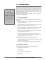
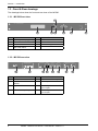
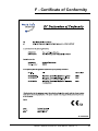
MC500
Network Time Server
User Manual
Version 1.3
Safety Precautions
To reduce the risk of fire, or electric shock, do not allow the
MC500 to be exposed to rain or moisture.
To avoid the risk of electric shock, do not open the enclosure.
This unit is designed to be installed into an equipment rack or on
a suitable flat surface. Do not install this product on an uneven
surface.
To prevent damage to the unit, clean only with a dry cloth.
Use this product only with the supplied power adapter. If the
power adapter becomes damaged, consult a qualified electrician
for advice.
The supplied power adapter is intended to serve as a disconnect
device. The socket-outlet should be installed near the equipment
and should be easily accessible.
Certification
Copyright
© 2013 - 2015 World Time Solutions Limited. All Rights Reserved.
All information contained within this document is the property of
World Time Solutions Limited and cannot be used or reproduced
by any person or company without written consent from World
Time Solutions Limited.
World Time Solutions Limited reserves the right to make periodic
amendments to the information in this document without notice.
Trademarks
Microsoft, Windows, Windows XP, Vista and Windows 7 are either
registered trademarks or trademarks of Microsoft Corporation in
the United States and other countries.
All other registered trademarks and trademarks are property of
their respective owners.
Software Licence
In accordance with European Directives 2006/95/EC (The Low
Voltage Directive) and 2004/108/EC (The Electromagnetic
Compatibility Directive), the MC500 is in conformity with the
applicable requirements of BS EN 60950-1:2006 (Information
Technology Equipment - Safety), BS EN 55022:2006 (Information
Technology Equipment - Radio disturbance characteristics - class
B) and BS EN 55024:2003 (Information Technology Equipment Immunity characteristics).
A copy of the EC Declaration of Conformity is included at the rear
of this user manual. Copies of the original document may be
downloaded from our web site at:
www.worldtimesolutions.com
RoHS Compliance
World Time Solutions Limited works with it’s suppliers to ensure
all products comply with the Restriction of Hazardous Substances
(RoHS) directive.
For further information, please visit our web site at:
This product contains proprietary World Time Solutions Limited
software. This proprietary World Time Solutions Limited software
is supplied under the World Time Solutions Limited Software
Licence Agreement.
To obtain further information and/or a copy of the software licence
please visit:
www.worldtimesolutions.com
Limited Warranty
The MC500 Network Time Server is guaranteed against failure
due to faulty parts or workmanship for a period of five (5) years
from date of purchase.
In the event of product failure due to faulty parts or workmanship
within the warranty period, World Time Solutions Limited, at
its own discretion, will either (a) repair the product, (b) supply
a replacement product, (c) supply a functionally equivalent
replacement product, or (d) refund the purchase price of the
product.
www.worldtimesolutions.com/rohs.html
The limited warranty will not apply if (a) the product has not been
installed or operated as per our instructions, (b) the product has
been modified in anyway.
Disposal
In the event of failure, the MC500 should be returned to the
manufacturer for inspection and repair. Please visit our support
pages for further details:
www.worldtimesolutions.com/support.html
Please dispose of this unit properly. To minimize pollution and
help protect the environment, this unit should be recycled.
For further information and/or to view a copy of the World Time
Solutions Limited Waste Electrical and Electronic Equipment
Policy, please visit our web site at:
Technical Support
To obtain help with the installation or operation of the MC500,
please visit our web site at:
www.worldtimesolutions.com/support.html
www.worldtimesolutions.com/recycle.html
II
MC500 - Network Time Server - User Manual - Version 1.3
Contents
1 - Introduction.....................................................................................................................1
1.1 - Quick start guide....................................................................................................................... 1
1.2 - Package contents..................................................................................................................... 1
1.3 - Front & Rear drawings.............................................................................................................. 2
1.4 - LCD time and status displays................................................................................................... 3
2 - Installing the MC500.......................................................................................................4
2.1 - Physical installation.................................................................................................................. 4
2.2 - Remote synchronisation input connections.............................................................................. 4
2.3 - Power connection..................................................................................................................... 5
2.4 - Local area network connection................................................................................................. 5
2.5 - RS-232 output.......................................................................................................................... 5
2.6 - Earth connection....................................................................................................................... 5
3 - Network setup.................................................................................................................6
3.1 - How to enter the network setup menu...................................................................................... 6
3.2 - Changing the DHCP setting..................................................................................................... 6
3.3 - Programming static IP settings................................................................................................. 7
3.4 - NTP Broadcast......................................................................................................................... 7
4 - RS-232 output..................................................................................................................8
4.1 - Connecting to the RS-232 output............................................................................................. 8
4.2 - RS-232 data message format................................................................................................... 8
4.3 - RS-232 transmission parameters............................................................................................. 8
4.4 - RS-232 time zone..................................................................................................................... 9
4.5 - PPS (pulse per second) output................................................................................................ 9
4.6 - Configuring the RS-232 / PPS output..................................................................................... 10
5 - Setting the time zone.................................................................................................... 11
4.1 - Setting the local time zone..................................................................................................... 11
6 - Advanced setup.............................................................................................................12
6.1 - Accessing advanced setup..................................................................................................... 12
7 - Software updates..........................................................................................................14
7.1 - Downloading the Software Update Utility............................................................................... 14
7.2 - Installing the Software Update Utility...................................................................................... 14
7.3 - Downloading the updated software version........................................................................... 15
7.4 - Applying a software update.................................................................................................... 15
A - Troubleshooting............................................................................................................16
B - RS-232 message formats.............................................................................................17
C - Menu structure..............................................................................................................18
D - Time zones....................................................................................................................20
E - Specifications...............................................................................................................22
F - Certificate of Conformity..............................................................................................23
MC500 - Network Time Server - User Manual - Version 1.3
III
1 - Introduction
What is NTP?
Network Time Protocol (NTP)
enables the synchronisation
of computer clocks across data
networks. It was originally
proposed in the early 1980s
and has been continually
updated and used ever since.
Further information may be
found at the home of the NTP
project:
http://www.ntp.org
The World Time Solutions MC500 is a Network Time Server with an
Ethernet port and an RS-232 serial output. The MC500 obtains time
information from a connected antenna and uses this data to service
NTP time requests from multiple devices on a TCP/IP network. The
MC500 also provides RS-232 level time and date information and
PPS (Pulse Per Second) data.
The MC500 is based around World Time Solutions proprietary
software for enhanced security.
1.1 - Quick start guide
The following list of procedures can be used for rapid installation of
the MC500:
• Install the MC500 into a 19” equipment rack or on a suitable
surface (see section 2.1).
• Install and connect a suitable antenna system to one of the
remote synchronisation inputs (see section 2.2).
• Connect the MC500 to a suitable 100-240 VAC mains power
supply via the supplied power adapter (see section 2.3).
• Enter the required network address settings or set the MC500 for
DHCP operation (see section 3).
• Select the local time zone (see section 4.1 & appendix D).
• Connect the MC500 to your TCP/IP Ethernet network via a
network switch or hub (see section 2.4).
The following optional procedure may also be performed:
• If required, configure the RS-232 serial time and date / PPS
(Pulse Per Second) outputs.
• If required, connect the RS-232 serial port to a third-party device.
1.2 - Package contents
The MC500 is supplied with the following component parts:
• MC500 Network Time Server
• Power adapter
• CAT5 patch & RS-232 serial cables
• User manual
MC500 - Network Time Server - User Manual - Version 1.3
1
Section 1: Introduction
1.3 - Front & Rear drawings
The drawings below show the front and rear view of the MC500.
1.3.1 - MC500 front view
2
MC500 - NETWORK TIME SERVER
STATUS
SETUP
ENTER
1
No.
Function
3
No.
4
5
6
7
Function
1
Liquid crystal display (LCD)
5
Multifunction switches
2
Status switch
6
Enter switch
3
Setup switch
7
Rack mounting ears
4
Back / Exit switch
Table 1.1 - Front panel functions
1.3.2 - MC500 rear view
24V DC (0.5A)
MC500 - Network Time Server
WORLD TIME SOLUTIONS LIMITED
www.worldtimesolutions.com
-
8
No.
Function
No.
SOFTWARE
UPDATE
RS-232
DATA OUTPUT
ETHERNET
11
12
13
Function
8
Earth point
12
RS-232 data / PPS output
9
Serial number / MAC
address
13
Ethernet port
10
DC power inlet
14
Remote Synchronisation Port
Sync 1 input
11
USB software update port
15
Remote Synchronisation Port
Sync 2 input
Table 1.2 - Rear panel functions
2
REMOTE SYNCHRONISATION INPUTS
SYNC 1
SYNC 2
A B C D
A B C D
+
10
9
World Time
Solutions
BACK
NETWORK TIME SERVER
MC500 - Network Time Server - User Manual - Version 1.3
14
15
Section 1: Introduction
1.4 - LCD time and status displays
In normal operation, the liquid crystal display (LCD) shows the local
time and date and synchronisation status. The MC500 also has three
status display screens accessible via the ‘STATUS’ switch. The status
display screens show basic information from the connected antenna
systems and the status of the network interface.
1.4.1 - Standard time and date display
19
20
21
No.
Function
19
Local date
20
Local time
No.
21
Function
Synchronisation status
Table 1.3 - Standard time and date display functions
1.4.2 - Sync 1 & Sync 2 status displays
The Sync 1 status display is accessible by pressing the ‘STATUS’
switch on the front panel. With a further press of the status switch, a
similar Sync 2 status display is shown.
22
23
No.
22
Function
Antenna system type
No.
23
Function
Antenna status
Table 1.4 - Sync 1 status display functions
1.4.3 - Network status display
The Network status display is located after the two sync status
display screens. This can be accessed by a further depression of the
‘STATUS’ switch. Press the status switch again to exit.
24
No.
24
Function
Network status
Table 1.5 - Network status display functions
MC500 - Network Time Server - User Manual - Version 1.3
3
2 - Installing the MC500
The MC500 is supplied in a robust metal case suitable for mounting
into an industry standard 19” rack. The system is supplied with an
external power adapter and also requires a connection to your local
area network and connection to a compatible World Time Solutions
Time Receiver System.
System setup should be performed using the front panel switches.
2.1 - Physical installation
The MC500 has been designed for installation into an industry
standard 19” rack. The unit is 1U (44mm - 1.75”) high.
2.2 - Remote synchronisation input connections
The MC500 has two remote synchronisation inputs for connection
to compatible World Time Solutions Time Receiver systems. The
MC500 is designed to operate with either one or two antenna systems
connected. In installations using two antenna systems, the MC500
uses the second antenna as a live backup system.
2.2.1 - Installing the antenna system
The antenna system/s should be installed as specified in the
accompanying installation guide.
2.2.2 - Connecting the antenna system to the MC500
The antenna system/s should be connected to one of the Remote
Synchronisation Inputs using the supplied cable. Connections should
be made as shown in the installation guide accompanying the antenna
system. Please also refer to the antenna installation guide for details
of how the cable may be extended.
REMOTE SYNCHRONISATION INPUTS
SYNC 1
SYNC 2
A B C D
A B C D
(If required, this cable may be
extended as detailed in the
installation guide accompanying
the antenna system.)
4
MC500 - Network Time Server - User Manual - Version 1.3
Section 2: Installing the MC500
2.2.3 - Antenna system setup and status
The MC500 monitors the status of any connected antennae and
automatically selects the most stable and accurate as a synchronisation
reference source.
All compatible World Time Solutions Time Receiver systems
incorporate setup information into data messages sent to the MC500.
This setup information is used by the MC500 to perform any required
setup changes automatically. Therefore, new or different antenna
systems can be connected to the MC500 in the future without any
programming changes by the user.
Detailed information regarding antenna synchronisation status may
be obtained via the sync status screens (see section 1.4.2).
2.3 - Power connection
The MC500 is supplied with an external power adapter. The power
adapter should be connected to the MC500 before being connected
to a local mains power supply.
2.4 - Local area network connection
PLEASE NOTE: In order to prevent possible network setup conflicts, it is
recommended that the MC500 is not connected to the network before the Network
Setup Procedure in section 3 has been completed.
The MC500 should be connected to an Ethernet switch/hub on a
TCP/IP network. The MC500 has a 10BASE-T/100BASE-TX autosensing Ethernet port and should be connected to the network using
the supplied CAT5 patch cable (or similar).
2.5 - RS-232 output
The MC500 has an RS-232 data output providing user programmable
serial time and date messages and PPS (Pulse Per Second) data.
Please refer to section 4 for connection and setup details.
2.6 - Earth connection
To ensure compliance with the relevant Electromagnetic Compatibility,
Radio disturbance and Immunity standards, the MC500 should be
connected to a suitable earthing point using the rear Earth binding
post.
MC500 - Network Time Server - User Manual - Version 1.3
5
3 - Network setup
The Ethernet port enables the MC500 to be connected to a TCP/IP
network via an Ethernet switch or hub (see section 2.4).
The network interface may be programmed to operate with DHCP
enabled or disabled. When DHCP operation is enabled, the MC500
attempts to obtain network address settings automatically from a
DHCP server on the network. With DHCP disabled, network address
settings are manually entered into the unit.
3.1 - How to enter the network setup menu
The network setup menu can be accessed using the front panel
switches as shown in the graphic below:
What is DHCP?
Dynamic Host Configuration
Protocol (DHCP) enables the
automatic assignment of IP
address settings on a TCP/IP
network.
Upon connection to a
TCP/IP network, a client
device configured for DHCP
operation communicates with
the DHCP server and obtains
an IP address lease.
The DHCP protocol is defined
in RFC 2131, available for
download from:
http://www.rfc-editor.org
SETUP
ENTER
3.2 - Changing the DHCP setting
As shown in the graphic on the following page, with the MC500 in the
network setup menu and the DHCP option screen displayed, pressing
either the ‘UP’ or ‘DOWN’ switches will toggle the DHCP mode. When
the correct mode has been selected, pressing the ‘ENTER’ switch will
forward on through the remaining network setup menu options.
If DHCP is enabled, the remaining network setup screens will show
the IP settings obtained from the DHCP server. If the MC500 has
not yet obtained a DHCP lease, the IP address, subnet and gateway
screens will show ‘---.---.---.---’ in place of a valid network address.
The status of the network connection may be confirmed by displaying
the network status screen (see section 1.4.3).
From this point, the network setup menu may be exited by a further
four presses of the ‘ENTER’ switch.
6
MC500 - Network Time Server - User Manual - Version 1.3
Section 3: Network setup
ENTER
IP address screen before a
DHCP lease is obtained.
IP address screen after a
DHCP lease is obtained.
3.3 - Programming static IP settings.
If DHCP operation is disabled, the MC500 uses the IP address, subnet
and gateway address as programmed in the network setup menu.
The IP settings can be adjusted using the multi-function switches.
Pressing the ‘ENTER’ switch will move on to the next screen.
3.4 - NTP Broadcast
In a typical computer network, NTP operates in Unicast mode: an
NTP client requests the time and the MC500 NTP server responds
directly to this request. However, in certain applications, it may be
desirable to configure the MC500 to operate in broadcast mode.
When operating in NTP broadcast mode, as well as responding directly
to Unicast NTP requests, the MC500 additionally broadcasts NTP
messages to all devices on the local subnet. Broadcast messages
are transmitted every 64 seconds.
MC500 - Network Time Server - User Manual - Version 1.3
7
4 - RS-232 output
The RS-232 data output provides time and date information at RS‑232
signal levels. The data format can be chosen by the user from a list of
more than 20 different formats.
The RS-232 port also outputs high accuracy PPS (pulse per second)
data at RS-232 signal levels.
4.1 - Connecting to the RS-232 output
The MC500 has a female DB-9 (DE-9) D-Sub (DTE) connector. Table
4.1 shows the pin connections.
Pin
Signal
Source
Description
1
PPS
Output
Pulse Per Second
2
TXD
Output
Transmitted data
3
RXD
Input
Received data
5
GND
Input
Signal ground
4, 6 - 9
unused
-
-
Table 4.1 - RS-232 serial port pin connections
4.2 - RS-232 data message format
Serial data is transmitted in one of more than 20 ‘message formats’.
Available message formats are listed in appendix B.
The message format can be adjusted in the RS-232 output setup
menu (as shown in the diagram on page 10).
4.3 - RS-232 transmission parameters
RS-232 messages can be transmitted at various different baud rates
and with different numbers of data bits, stop bits and parity settings.
All of these parameters can be adjusted by the user via the RS-232
output setup menu (shown in the diagram on page 10). Table 4.2 lists
the available transmission parameters.
RS-232 data messages are transmitted aligned with the second edge.
The MC500 can be user-programmed to output an RS-232 data string
every second, or periodically (as detailed in table 4.2).
When set to the ‘on demand’ repetition rate, the MC500 will only
output serial data on receipt of a valid transmission request character.
Valid characters are ‘s’ (0x73), ‘S’ (0x53), ‘t’ (0x74), ‘T’ (0x54) and ‘?’
(0x3f). The data transmission starts on the second edge after a valid
request character has been received.
8
MC500 - Network Time Server - User Manual - Version 1.3
Section 4: RS-232 output
4.4 - RS-232 time zone
As standard, the MC500 transmits RS-232 time and date information
referenced to the local time zone (please refer to chapter 5 for further
details). If required, RS-232 data can be referenced to UTC by
adjusting the ‘RS-232 time zone’ in the RS-232 output setup menu
(as shown on page 10).
RS-232 Output
Menu Option
Description Of
Function
Message format Format of RS-232 data
messages.
Available options
Please refer to appendix B
Baud rate
Data transmission speed 1200, 2400, 4800, 9600,
(bits per second)
19200
Data bits
Number of data bits
7, 8
Parity
Error checking
none, odd, even
Stop bits
Number of stop bits
1, 2
Repetition rate
Time period between
message transmissions
1 sec, 1 min, 5 mins, 1 hr,
24 hours (at 00:00),
24 hours (at 03.30),
on demand
RS-232 time
zone
Time & date to which
the RS-232 output is
referenced
local, utc
PPS output
polarity
The polarity of the PPS
output pulse
standard, inverted,
disabled
PPS pulse width Length of each PPS
pulse
20 msec, 100 msec,
200 msec
Table 4.2 - RS-232 output menu options
4.5 - PPS (pulse per second) output
PPS (pulse per second) data is available on pin 1 of the RS-232
output port. When enabled, the PPS pin provides a short pulse every
second, aligned with the second edge. PPS data is transmitted at
RS-232 signal levels.
When set to standard output polarity, the pin is normally at a negative
voltage level (RS-232 logic state 1). At the start of the second edge,
the pin switches to a positive voltage level (RS-232 logic state 0).
After the PPS pulse has ended, the pin switches back to a negative
voltage level.
When set to inverted operation, pin polarity is the opposite of standard
operation (normally held at logic state 0, switching to logic state 1 at
the second edge).
The width of the PPS pulse may be adjusted from 20 msec to 200
msec.
Please refer to the diagram on page 10 for details of adjusting these
parameters.
MC500 - Network Time Server - User Manual - Version 1.3
9
Section 4: RS-232 output
4.6 - Configuring the RS-232 / PPS output
The RS-232 output configuration menu can be accessed using the
front panel switches as detailed below:
SETUP
ENTER
ENTER
ENTER
ENTER
ENTER
ENTER
ENTER
ENTER
ENTER
ENTER
10
MC500 - Network Time Server - User Manual - Version 1.3
5 - Setting the time zone
What is UTC?
In the early 1970s, with the
increase in timing accuracy
made available by modern
atomic clocks, Coordinated
Universal Time (UTC) replaced
Greenwich Mean Time (GMT)
as the world’s time scale.
Historically, GMT calculated
the length of a day based on
solar time patterns. UTC uses
highly accurate atomic clocks
as a calculation base.
See also... ‘What is a leap
second?’ (section 6).
The MC500 maintains a time count for both UTC (see side panel for
further details) and local time. The UTC count is used as a reference
for NTP (Network Time Protocol) time stamps. The local time count
is shown on the LCD display (enabling simple user-monitoring of time
accuracy) and is normally used as a reference for the RS-232 data
output (in certain applications, the user may wish to reference RS-232
data to the UTC time count - refer to chapter 4 for further details).
As part of the initial setup procedure, the user should select the
local time zone from a preprogrammed list. Where applicable, the
preprogrammed time zones incorporate seasonal time change
information, allowing changes to occur automatically.
Appendix D lists the preprogrammed time zones along with offsets
from UTC. The time zone may be adjusted following the procedure
detailed below.
4.1 - Setting the local time zone
The local time zone should be adjusted as shown in the diagram
below. Once the local time zone screen is displayed, the selected
time zone can be adjusted using either the ‘UP’ or ‘DOWN’ multifunction switches. Please refer to appendix D for details of available
preprogrammed time zones.
SETUP
ENTER
ENTER
MC500 - Network Time Server - User Manual - Version 1.3
11
6 - Advanced setup
The Advanced Setup menu contains various settings, most of which
typical users should not need to access or adjust. Settings may be
adjusted following the procedure detailed in section 6.1 below.
The table below details the options in the Advanced Setup menu:
Advanced Setup
Menu Option
Description Of Function
What is a leap second?
Set local time
Allows local time to be adjusted. This should only
be adjusted if the MC500 has no active remote
synchronisation reference. Note that before
adjusting this setting, the time zone must be
programmed (see section 5.1).
The average rotational speed
of the earth is very slowly
decreasing and therefore the
average length of a solar day
is very slowly increasing.
Set local date
Allows local date to be adjusted. This should only
be adjusted if the MC500 has no active remote
synchronisation reference. Note that before
adjusting this setting, the time zone must be
programmed (see section 5.1).
Leap second
Enables the user to manually set a positive (1
second added) or negative (1 second removed)
leap second (see side bar). If programmed, the
leap second will occur once only at the end of the
following June or December (which ever occurs
first) and then be erased.
To enable time counts based
on solar day observations to
be kept in alignment with
international time scales, an
extra second is occasionally
added to UTC at the end of
June or December.
Display contrast
Allows adjustment of liquid crystal display
contrast to aid viewing at different angles.
Display power save
When enabled, switches off liquid crystal display
backlight if switches have not been active for 2
mins.
Serial number
MC500 serial number. (Read only)
MAC address
Media Access Control address. (Read only)
Software version
Current software version. (Read only)
Hardware version
MC500 build revision. (Read only)
SYNC 1 software
SYNC 1 software version. (Read only)
SYNC 1 hardware
SYNC 1 build revision. (Read only)
SYNC 2 software
SYNC 2 software version. (Read only)
SYNC 2 hardware
SYNC 2 build revision. (Read only)
Language
Current language.
Table 6.1 - Advanced Setup menu options
6.1 - Accessing advanced setup
The advanced setup configuration can be confirmed using the
procedure shown in the diagram on the following page.
12
MC500 - Network Time Server - User Manual - Version 1.3
Assuming the MC500 is
connected to a leap second
capable antenna system,
leap seconds will be handled
automatically, with the leap
second setting (found in the
Advanced Setup menu) being
adjusted up to one month in
advance of the event.
See also... ‘What is UTC?’
(section 5).
Section 6: Advanced setup
SETUP
ENTER
ENTER
ENTER
ENTER
ENTER
ENTER
ENTER
Some screens display read only
values (e.g. software version), others
show values that may be adjusted.
If a particular setting can be adjusted,
the value will be flashing on the
screen and the ‘UP’ and ‘DOWN’
multi-function switches used to adjust
the value. If multiple values can be
adjusted (e.g. local time setup), the
‘LEFT’ and ‘RIGHT’ multi-function
switches can be used to move
between values.
ENTER
ENTER
ENTER
ENTER
ENTER
ENTER
ENTER
ENTER
MC500 - Network Time Server - User Manual - Version 1.3
13
7 - Software updates
Occasionally, an updated software version may become available
for the MC500. The updated software should be installed using the
MC500 Software Update Utility.
The MC500 Software Update Utility and any available software
updates can be downloaded from the World Time Solutions web site:
http://www.worldtimesolutions.com
7.1 - Downloading the Software Update Utility
PLEASE NOTE: The Software Update Utility should be downloaded and the USB
drivers installed prior to connecting the MC500 to the PC.
The following procedure should be performed on a Microsoft®
Windows® XP SP3, Windows Vista™ or Windows® 7 PC:
• Visit the World Time Solutions web site and navigate to the
MC500 downloads page.
• Right click the MC500 Software Update Utility and select ‘Save
link as...’
• Select a directory on your computer.
For troubleshooting advice, please refer to appendix A.
7.2 - Installing the Software Update Utility
• Navigate to the directory with the MC500 Software Update Utility
(previously downloaded in section 7.1 above).
• Right click the MC500 Software Update Utility zip file and select
‘Extract All...’
• Follow the instructions on screen to extract the zip file to a new
directory.
• Navigate to the new directory and double click the utility installer
MC500_Utility_Installer.exe. (If an ‘Open File - Security Warning’
appears, select ‘Run’ to continue installation.)
• In the MC500 Utility Installer window, click ‘Install USB Drivers’.
• Once the USB drivers have been installed, connect the MC500
to the PC using a standard USB printer cable.
• In the MC500 Utility Installer window, click ‘Install MC500
Software Update Utility’. The MC500 Software Update Utility will
start automatically.
For troubleshooting advice, please refer to appendix A.
14
MC500 - Network Time Server - User Manual - Version 1.3
Section 7: Software updates
7.3 - Downloading the updated software version
• Visit the World Time Solutions web site and navigate to the
MC500 downloads page.
• Right click the new MC500 software version and ‘Save link as...’
• Select a directory on your computer.
For troubleshooting advice, please refer to appendix A.
7.4 - Applying a software update
• Navigate to the directory with the new MC500 software version
(previously downloaded in section 7.3 above).
• Right click the new software zip file and select ‘Extract All...’
• Follow the instructions on screen to extract the zip file to a new
directory.
The remaining steps are performed using the MC500 Software
Update Utility.
• In the section labelled ‘Software Version’ the current software
version is shown. Click the ‘Browse’ button. A ‘File Open’ window
will appear.
• Select the recently downloaded and extracted file (MC500T_x.x)
and click ‘Open’. The new file version will now be displayed in
the ‘Replacement Software Version’ text box.
• Click the ‘Start Update Procedure’ button. The replacement
software will now be uploaded into the MC500 via the USB
connection. The ‘Software Update Progress’ section details the
procedures being performed and overall progress.
• Once the update is complete, click on the ‘Exit’ button.
For troubleshooting advice, please refer to appendix A.
MC500 - Network Time Server - User Manual - Version 1.3
15
A - Troubleshooting
Problem
Possible Cause
Time synchronisation
error
Antenna not
synchronised
Solution
Check sync status screen
(see section 1.4)
Refer to antenna user
guide
Not responding to
NTP requests
Cabling fault
Refer to antenna user
guide (and section 2.2.2)
No connection to
network
Check connection to
network switch/hub
Check CAT5 patch cable
integrity
MC500 time not set
Refer to Time
synchronisation error
section above
If not using an antenna
system, manually set
local time and date (see
section 6)
‘MC500 not found’
error displayed in
MC500 Software
Update Utility
MC500 USB interface
not detected by
Software Update
Utility at startup
Check USB connection
between MC500 & PC
(see section 7)
‘Communication
failure’ error
displayed in MC500
Software Update
Utility
Unspecified comms
Check USB connection
error between MC500 between MC500 & PC
and PC
(see section 7)
‘USB data error’
displayed in MC500
Software Update
Utility
Error checking failure
between MC500 and
PC
Liquid crystal display
hard to read
Contrast set
incorrectly
Adjust LCD contrast (see
section 6)
Liquid crystal display
backlight switching
off automatically
LCD power save
mode enabled
Disable LCD power save
mode (see section 6)
RS-232 output not
functional
RS-232 output
Check all RS-232 output
configured incorrectly settings (see section 4)
PPS output not
working as expected
PPS output
Check PPS settings (see
configured incorrectly section 4)
Check USB cable (see
section 7)
Check USB cable (see
section 7)
Check USB connection
between MC500 & PC
(see section 7)
Check USB cable (see
section 7)
Table A.1 - Troubleshooting guide
16
MC500 - Network Time Server - User Manual - Version 1.3
B - RS-232 message formats
The table below lists the RS-232 message formats. Please refer to
chapter 4 for further details.
No.
Message format
1
World Time Solutions standard format
2
World Time Solutions long format
3
World Time Solutions short format
4
NMEA GGA
5
NMEA RMC
6
NMEA ZDA
7
Spectracom NetClock/2 format 0
8
Spectracom NetClock/2 format 1
9
Spectracom NetClock/2 format 2
10
Spectracom NetClock/2 format 3
11
Spectracom NetClock/2 format 4
12
EES M100
13
EES M201
14
Meinberg Standard time string
15
Computime Time String
16
Sysplex 1
17
Wtn. format 1
18
Wtn. format 1 (without status)
19
Wtn. format 2
20
Wtn. format 2 (with day of week)
21
Racal XGU
22
Tecton Darlex
23
TAIP AL (Altitude / Vertical Velocity)
24
TAIP CP (Compact Position)
25
TAIP LN (Long Navigation)
26
TAIP PV (Position / Velocity)
27
TAIP TM (Time / Date)
Notes
(03:30 & 03:31 only)
Table B.1 - RS-232 message formats
MC500 - Network Time Server - User Manual - Version 1.3
17
C - Menu structure
The flow diagram below shows the basic structure of the MC500
programming menu.
STATUS
STATUS
SETUP
ENTER
ENTER
ENTER
(Refer to section 3 for
details of network settings)
ENTER
ENTER
ENTER
ENTER
ENTER
(Refer to section 4 for details
of RS-232 output settings)
(Remaining RS-232 output menu screens
have been omitted to aid clarity. Please
refer to chapter 4 for further details)
ENTER
ENTER
18
ENTER
MC500 - Network Time Server - User Manual - Version 1.3
Appendix C: Menu structure
PLEASE NOTE: Some detail has been omitted from this diagram to aid clarity.
STATUS
ENTER
ENTER
STATUS
ENTER
(Refer to section 5 for details
of time zone setting)
ENTER
(Refer to section 6 for details
of advanced settings)
ENTER
ENTER
ENTER
(Remaining Advanced Setup menu screens
have been omitted to aid clarity. Please
refer to chapter 6 for further details)
ENTER
MC500 - Network Time Server - User Manual - Version 1.3
19
D - Time zones
The table below lists the preprogrammed time zones. Time zone
offsets followed by a * character indicates that the time zone has
daylight saving changes.
UTC Offset
City / Time Zone
0
UTC/Reykjavik
0*
London/Dublin/Lisbon
0*
Casablanca
+1
Lagos/Algiers
+1*
CET/Paris
+2
Cape Town/Johannesburg/Harare
+2*
Athens/Sofia
+2
Cairo
+2*
Jerusalem
+2*
Beirut
+2*
Amman
+3
Khartoum/Nairobi/Baghdad
+3*
Moscow (old)
+3.5*
Tehran
+4
Dubai/Moscow
+4.5
Kabul
+5
Karachi
+5.5
Mumbai/New Delhi
+5.75
Kathmandu
+6
Almaty/Dhaka
+6.5
Yangon
+7
Bangkok/Jakarta
+8
Singapore/Hong Kong/Beijing
+8*
Perth
+9
Seoul/Tokyo
+9.5
Darwin
+9.5*
Adelaide
+10
Brisbane
+10*
Vladivostok
+10*
Melbourne/Canberra/Sydney
+11
-
+12
Suva
+12*
Kamchatka/Anadyr
+12*
Auckland
+12.75*
Chatham Island
+13
-
+14
Kiritimati
Table D.1 - Preprogrammed Time Zones
20
MC500 - Network Time Server - User Manual - Version 1.3
Appendix D: Time zones
UTC Offset
City / Time Zone
-10
Honolulu
-9
-
-9*
Anchorage
-8
-
-8*
Vancouver/San Francisco
-7
Phoenix
-7*
Edmonton/Denver
-6
Guatemala/San Salvador/Managua
-6*
Winnipeg/Houston/Chicago
-6*
Mexico City
-5
Lima/Kingston/Bogota
-5*
New York/Toronto/Nassau
-5*
Havana
-4.5
Caracas
-4
Santo Domingo/La Paz/San Juan
-4*
Halifax
-4*
Santiago
-3.5*
Newfoundland
-3
-
-3*
Brasilia/Sao Paulo
-3*
Montevideo
-3
Buenos Aires
-2
-
-1
-
Table D.1 - Preprogrammed Time Zones (cont..)
MC500 - Network Time Server - User Manual - Version 1.3
21
E - Specifications
Typical Performance Specifications
Synchronised internal
timing accuracy:
Dependent on synchronisation source
accuracy, time elapsed from first lock and
cable lengths. Typically within 100nsec of
synchronisation source after 30 mins.
NTP/SNTP Client
synchronisation accuracy:
Dependent on network architecture,
utilisation, delays and jitter. Clients typically
synchronised to within 200 µsec to 2 msec
of MC500 on a local area network.
RS-232 output accuracy:
50 µsec
PPS output accuracy:
1 µsec
PPS output jitter:
100 nsec
Supported Protocols
NTP v2 (RFC 1119), NTP v3 (RFC 1305), NTP v4 (no RFC),
SNTP v3 (RFC 1769), SNTP v4 (RFC 2030), DHCP
I/O Connections
Ethernet:
10BASE-T / 100BASE-TX auto-sensing
RS-232 / PPS:
DB-9 (DE-9) female D-Sub (DCE)
Software update:
USB Specification 2.0 compliant full-speed
(12 Mbit/s)
Synchronisation inputs:
2 x dual-redundant 1000 series antenna
connection ports
Power input:
24 VDC power input, supplied with external
power adapter
Mechanical & Electrical Specifications
Dimensions:
483 x 44 x 120 mm (19.0” x 1.73” x 4.72”)
Weight:
2 kg
Power consumption:
0.5 AMPS (@ 24 VDC)
Environmental Specifications
Operating temperature:
0 to 50 ºC
Relative humidity:
0% - 95%, noncondensing
Standards
Electrical Safety:
BS EN 60950-1:2006
Radio Disturbance:
BS EN 55022:2006 (class B)
Immunity Characteristics:
BS EN 55024:2003
22
MC500 - Network Time Server - User Manual - Version 1.3
F - Certificate of Conformity
MC500 - Network Time Server - User Manual - Version 1.3
23
World Time Solutions Limited
1st Floor, Barclays House, Gatehouse Way, Aylesbury, Buckinghamshire, HP19 8DB, United Kingdom
+44 (0) 1296 331428 - [email protected]
www.worldtimesolutions.com