1
ELECTRICAL CONNECTION (POWER CIRCUIT)
SECTION 4
ELECTRICAL CONNECTION (POWER CIRCUIT)
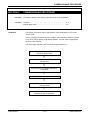
Overview : This section details the power circuit for CFI Series Drives.
Content
Connection
Procedure
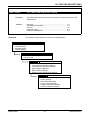
Connection Procedure .............................................................. 4-1
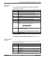
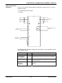
Dynamic Braking ....................................................................... 4-2
Supply Conditioning .................................................................. 4-2
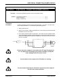
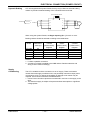
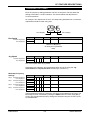
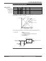
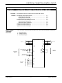
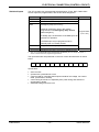
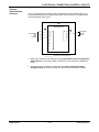
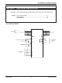
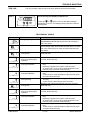
Connect the supply to the CFI power input terminals L1, L2 and L3, and the motor
to CFI output terminals U, V, W observing the following points :
1. Always earth the CFI
2. Always run the power cabling separately from control wiring to prevent electrical
interference on control circuits.
3. Use neutral screened cable to prevent RFI. The screen must be earthed at both
ends. Minimising the length of cable between the motor and inverter also acts to
reduce RFI. Dedicated RFI filters are available for connection on the line side of
the CFI if required.
CFI
L1
L1
U
L2
V
L3
W
1Ø SUPPLY
N
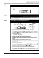
CAUTION
3 SUPPLY
M
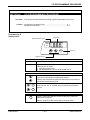
Ensure the power supply is connected to the CFI Input Terminals [L1,
L2, L3]. Application of voltage to the output terminals [U,V,W] will
cause damage to the CFI power circuit.
Do not switch on the output of the CFI while it is running.
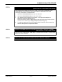
CAUTION
Do not connect Power Factor Correction capacitors to the output of
the CFI or the motor terminals.
CAUTION
CFI SERIES
-- 4-1--
USERS MANUAL