1
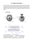
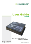
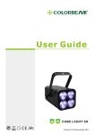
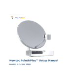
User Guide
POLARIS 200 DMX Control Systems
DRY
Version 1.0 December 2010
CONTENTS
1.
2.
3.
4.
5.
6.
7.
8.
ITEMS INCLUDED BEFORE UNPACKING......... 2
INTRODUCTION.............................................. 3
SPECIFICATION.............................................. 4
FUNCTION SCHEMA & INSTALLATION............ 5
WIRING DIAGRAM........................................... 5
WARNING....................................................... 6
OPERATION.................................................... 7
ORDER INFORMATION....................................10
www.colorbeam.com
1
ITEMS INCLUDED
Please make sure the below items were inlcuded when unpacking.
If there is anything missing, please call your local dealer immidently.
PO-200 Controller
The shape of the power cord plug
varies according to country or
geographic area.
Power cord
Housing Fixed Plate (2 pcs.)
Screw(8pcs.)
Wall /Floor Fixed Plate (4pcs.)
Robber Foot (4pcs.)
www.colorbeam.com
2
INTRODUCTION
COLORBEAM's newly developed PO-200 driver system is engineered
specifically for the Polaris range products. The multi-functional PO-200
can be installed on the wall, ground or embedded in the housing. Its light
and handy design provides flexibility and freedom to accommodate all types
of spaces with ease. Four miniaturized driver modules are linked into a
main board inside PO-200, making maintenance simple and effortless.
A wide variety of lighting effects can be adjusted via the friendly interface
on an easy to read LCD display. In addition to the standard DMX-512,
PO-200 offers built-in functions of 10 solid colors and 6 color-changing
effects to satisfy the challenging conditions form different scenarios.
Master/Slave mode enables synchronized control on multiple units.
Memory and timer capabilities are also included on PO-200 to further
simplify setting and operation for end users.
Features:
1. Total with 5 Modes: DMX Address Setting, Operation Mode,
Timer setting, Master Mode, Demo Mode
2. Simplified Installation
3. Effortless Maintenance
4. Friendly Interface
5. LCD Display
6. Various Lighting Effects.
7. Master/Slave Mode
8. Memory Capability
9. Timer Capability
10. Compact 1U standard
11. Available in 6 outputs and 8 outputs for different led color variants
www.colorbeam.com
3
SPECIFICATION
Electrical
Power Voltage: 90-264VAC, 50~60Hz
Power Consumption: 200W
Fuse : F5A / 250V (5x20mm Glass Fuse Tube)
Power Output: 6 way(RJ45)*24V/340±10mA (4 Colors)
8 way(RJ45)*24V/340±10mA (3 Colors)
Protocol: USITT DMX512-A
Communication
DMX Connecter: 5-PIN XLR
Output Connecter: RJ-45
Housing
Dimension(mm): L434 × W220.2 × H44
Weight: 3 KG
Material: Metal
Color: Black
Listing
Certifications: CE / RoHS / WEEE
Dimensions
0.24”
(6mm)
8.67”
(220.2mm)
8.67”
(220.2mm)
1.73”
(44mm)
1.73”
(44mm)
17.09”
(434mm)
17.09”
(434mm)
18.11”
(460mm)
18.03”
(458mm)
With housing fixed plate
With wall / floor fixed plate
www.colorbeam.com
4
FUNCTION SCHEMA
INSTALLATION
FUNCTION SCHEMA
POWER ON / OFF
LCD DISPLAY
BUTTON
5-PIN XLR
DMX IN
1
4
4
PORT NO.
1
2
3
1
2
3
4
5
6
7
4
5
6
8
3
5
5
3
2
DMX OUT
8 output / 3 colors
6 output / 4 colors
1
2
1. GND
2. D3. D+
4. N.C.
5. N.C.
INPUT
AC 90-264V,
50-60Hz
INSTALLATION
CAUTION:
Do not hot swap. Ensure that power to the fixture is off before
connecting or disconnecting fixtures.
1. Fix the fixture with bracket
2. Connect the AC power cord to the socket
AC input
100~240V / 50~60Hz
OR
ETC-5P/5B
Easy Touch Panel
DMX IN
Any other DMX
console and controller system
DMX OUT
Lights
NOTE: 6 Output /4 Colors of PO-200 isn’t compatible with ETC-5P/5B
WIRING DIAGRAM
Wiring Configuration
ETC-5P/5B
Easy Touch Panel
&
DMX console and
control systems
PO-200
DMX IN
200W, 1 output in total
24VDC, 340 ± 10mA
Lights
PO-200
DMX OUT
DMX IN
Lights
PO-200
DMX OUT
DMX IN
Splitter
RJ-3
Extension Connector
RJ-2
DMX OUT
Lights
Cable length max. 20m
NOTICE:
1. Please notice the idea of the wiring for all Colorbeam fixture is in series connection.
2. The wiring of the customized is different from the commercially available. Please refer our
accessory RJ-2 and RJ-3 to do the extension and the split.
3. The warranty will be invalid when the fixture is not under normal usage (including trimming the cable
and do wiring by user).
Please contact with your sales representative for the detailed information if the trimming will be happen.
www.colorbeam.com
5
WARNING
Read the instructions carefully before you install or powering!
CAUTION!
Be careful with your operations.
You can suffer a dangerous electric shock when touch the wires inside the unit.
1. Safety Instructions
Every person involved with installation and maintenance of the this device has to :
-be qualified.
-following the instructions of manual
Please make sure that there are no obvious transport damages.
Please immediately contact the local dealers as the device is in fault operation or damage.
Damages caused by the disregard of this user manual or unauthorized modification to
products are not subject to warranty.
Important
Keep this driver away from rain and moisture.
Unplug mains lead before opening the housing.
Make sure the plug is tightly connected with outlet.
Make sure all connector are connected properly.
Make sure the AC power that complies with local electrical codes.
Do not expose the device to heat source, corrosive, flammable or explosive area.
Do not block any of ventilation openings.
Do not open the device and try to repair the device personally.
2. Operation Determinations
The device must only be used indoor.
!
CAUTION!
For non-Colorbeam fixtures, refer to the
wiring diagram for installation.
I f the device has been exposed to drastic temperature fluctuation, do not switch it on
immediately. The arising condensation water might damage your device. Leave the device
switched off until it has reached room temperature.
Only operate the device after having checked the housing which is firmly closed and all
screws are tightly fastened. Do not shake the device. Avoid brute force when installing or
operating the device.
Operate the device only after having familiarized with its functions. Do not permit operation
by persons who are not qualified for operating the device. Most damages are the result of
unprofessional operation!
The maximum ambient temperature 40 degree must never be exceeded.
Please consider that unauthorized modifications on the device are forbidden due to safety
reasons!
www.colorbeam.com
6
OPERATION
Attention: It is import to read this manual before you install or use this product.
Primitive setting:
1. DMX Address No.: 001
2. DMX Group Mode: Independent
3. Master / Slave Mode: OFF
Press UP and DOWN to select the desired step from 1 to 4 below:
1. DMX add. Setting
For setting up DMX address, press Enter and the LCM display shows 001
twinkling. Press UP and DOWN to select the desired address from number 001-512.
When finish setting, press ENTER to Exit with save or ESC to Exit without save.
2. DMX Group Mode
There are four DMX group modes, first disconnect the DMX fconnector.
There are total 8 ports and can be set for different groups. Each group works
individually by using DMX console. When you see Group Mode, press ENTER
and the display shows independent twinkling. Press UP and DOWN to select the
desired group below:
(1) Independent: Control all ports individually
(2) Synchronize: Control all ports works in same operation
(3) Odd and Even: Port in Odd numbers in one group and
even numbers in the other group.
(4) Duet: Control ports by couple
When finish, press ENTER to exit with save or ESC to exit without save.
3. Timer Mode
In this function, the user can presetting turn on and turn off time for the lighting fixture.
Please go to the “Timer mode” function and press Enter to start setting. The setting
steps as below:
(1) After press enter to “ Timer Mode”, press UP or DOWN to select the mode
(F01-06, C01-06) that you wish to set time. When finish select the mode, the display
will twinkling. The press ENTER with save or ESC to Exit without save.
Note: For four color lighting fixture (ex: RGB+Warm white), the built in fixed color is
C01-C15)
(2) “On Time” setting: When finish first step, press DOWN go to “On time” mode
and press ENTER. When the display start twinkling, press UP or DOWN to select
the desire number and press ENTER with save or ESC to exit without save.
www.colorbeam.com
7
OPERATION
(3) “Off Time” setting: When finish second step, press DOWN go to “Off time” mode
and press ENTER. When the display start twinkling, press UP or DOWN to select the
desire number and press ENTER with save or ESC to exit without save.
(4) The forth step is for turn on the Timer mode. The display will show ”Timer is”
and press Enter. Then the display start twinkling, press UP or DOWN to select ”ON”
or ”OFF” and press ENTER with save or ESC to exit without save. Once finish this
step, there will have a colock sign appear on the display. It means the setting is
complete!
4. Master Mode
This function is to choose the main control when you connect above 2 controllers.
When you see Master, press ENTER and the display shows off twinkling. Press
UP and DOWN to select the master on or off. When finish, press ENTER to
Exit with save or ESC to Exit without save.
Note: Please pay attention for the below operation when use DMX console or
Colorbeam controller as the main control. It is to avoid the signals interrupted
each other.
(1) When use any DMX console as main control, please make sure the "Master
Mode” is in " OFF" condition on all Colorbeam controller.
(2) When use Colorbeam controller as the main control, please make sure there
is only one controller is in “ON”condition in Master Mode and others in
“OFF" condition.
5. Demo Mode
Please press ENTER and there are four programs in this mode:
(1) Fixed Color: There are 10 built-in fixed colors (3 Colors) / 15 built-in fixed colors
(4 Colors). Press UP and DOWN to select the desired color from C01~C10 / C15.
Note: The color illumination can be changed from 0~255 for each fixed color.
To change the color illumination press ENTER button. The display now shows
R255 G000 B000 (3 Colors) / R255G000B000A000 (4 Colors), the color value
twinkling can be adjust from 0~255 by pressing Up and Down. To confirm and
activate the color setting press Enter again to the next color setting.
3 Colors
4 Colors
www.colorbeam.com
8
OPERATION
(2) Fade Effect: There are 6 built- in fade effects. Press UP and DOWN to select
the desired effect from F01~ F06.
Note: The fade time of program can be changed from 01~99% ( 0. 5~ 50sec)
to set the fade time press the enter button. The display shows “Decay ratio”
, the fade time can be adjust from 01~99% by pressing UP and DOWN. To
confirm and activate time setting press enter again, or press exit to the next
program.
Remark: To have the output saved and work the same output when turn on the
PO-200 again, please press ENTER under the list of each C01~C15, F01~F06
and you will see “Status Saved” twinkling. The memory will stay on the latest
save only.
Please note the priority of directives should be DMX signal→Demo Mode.
(3) Self Test: Press ENTER to test one color on all lighting fixtures. Press
ENTER again to test the next color and so on.
(4) Reset to Initial: Press ENTER twice. The controller will return to the
original setting.
★ Standby Mode
The control unit will automatically into Standby mode in the event or not receiving
any instruction after 2 minutes. Under Standby mode, the control unit is
functional but display is off and keypad is locked. To leave Standby mode,
press and hold ENTER button for 3 seconds till display is on. When using
DMX Address control the fixture, the Standby mode will start after 2 minutes.
Press and hold Menu. button for 3 second to leave Standby mode.
SELECT LIST
First Layer
1. DMX Address
2. Group Mode
3. Timer Mode
4. Master Mode
5. Demo Mode
www.colorbeam.com
9
Second Layer
001~512
Independent
Synchronize
Odd & Even
Duet
Fixed Color / Fade Color
On Time
Off Time
Turn On / Off
ON/OFF
Fixed Color
Fade Color
Self Test
Reset to Initial
Third Layer
C01~C10
F01~F06
C01~C10
F01~F06
ORDER INFORMATION
ORDER INFORMATION FORM
CONTROLLER
ITEM
PO-200
SPEC.
PART NUMBER
8 Output / 3 Colors
GPOC0111
6 Output / 4 Colors
GPOC0112
ACCESSORY
ITEM
Extended line
RJ-45 two-way
SPEC.
PART NUMBER
5M
D03-456005-002
10M
D03-456010-001
Extended line
5pin XLR
5M
D03-505005-003
10M
D03-505010-001
Splitter
RJ-3
B0603-0100-1
Extension Connector
RJ-2
B0603-0100-3
Housing Fixed Plate
C01POC010701
Wall / Floor Fixed Plate
C01POC010702
Rubber Foot
E0299001
Screw
M4 x 5
E030504052
www.colorbeam.com
10
COLORBEAM CO. LTD.
314, 3F., No. 87, Minguang E. Rd.,
Taoyuan City, Taiwan 33052
TEL : +886 3 335 7716
FAX : +886 3 331 3386
E-MAIL : [email protected]
W : www.colorbeam.com