1
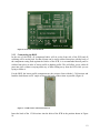
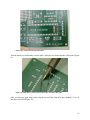
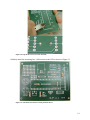
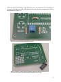
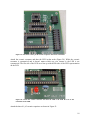
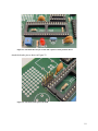
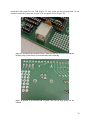
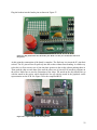
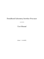
Figure 8: Front side of the BLIP PCB.
2.2.3 Constructing the BLIP
In the case of the BLIP, all component bodies will sit on the front side of the PCB and all
soldering will be on the back. So that all parts can be easily soldered into place with the body of
the component resting flush against the surface of the PCB, it is recommended that all parts be
soldered into place in order of lowest profile to highest profile. This will allow you to solder all
parts into place without worrying about any of them falling away from the PCB while you are
trying to solder it.
For the BLIP, the lowest profile components are the resistors. Start with the 1.5 kΩ resistor and
bend the leads down at a 90˚ angle as close to the body of the resistor as possible (Figure 9).
Figure 9: 1.5 kΩ resistor with leads bent down.
Insert the leads of the 1.5 kΩ resistor into the holes of the PCB in the position shown in Figure
10.
12