1
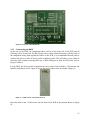
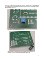
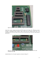
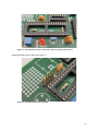
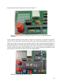
Attach the two 10 µF electrolytic capacitors (Figure 25). Make sure that the longer lead of the
capacitors go into the holes marked with a “+” symbol.
Figure 25: Attach the 10 µF capacitors to the PCB. Make sure you have their orientation
correct.
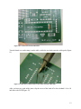
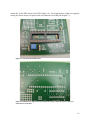
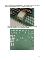
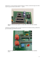
Attach the two pushbuttons (Figure 26). Be sure that the flat of the button is lined up with the flat
part of the button representation on the PCB.
Figure 26: Attach the two pushbuttons to the PCB. Make sure to have their orientation
correct.
21