1
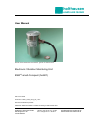
holthausen
elektronik GmbH
User Manual
Picture shows Aluminium-case without ground on earth terminal
Electronic Vibration Monitoring Unit
ESW®-small-Compact (hol601)
date: 22.07.2009
document: hol601_small_comp_hb_e.doc
technical modification possible
holthausen elektronik GmbH is certified according to DIN EN ISO 9001
holthausen elektronik GmbH
Wevelinghoven 38
41334 Nettetal
phone: +49 (0) 21 53 - 40 08
fax: +49 (0) 21 53 - 89 99 4
[email protected]
www.holthausen-elektronik.de
holthausen
Electronic Vibration monitoring Unit
ESW®-small-Compact
elektronik GmbH
Table of Contents
1. Generally basical safety-indications ............................ page 4
2. Packing and the transport ........................................... page 4
3. Application................................................................... page 5
4. Measurement principle ................................................ page 5
5. Grounding concept ...................................................... page 6
6. Mounting of the vibration control unit .......................... page 7
7. Opening and closing of the vibration control unit......... page 8
8. Maintenance................................................................ page 8
9. Display- and operation- elements................................ page 9
10. Measurement range switching .................................... page 10
11. Analog output .............................................................. page 10
12. Possible ground configurations ................................... page 10
13. Analog output settings ................................................. page 11
14. Adjustment of the limiting values ................................. page 11
15. Example to adjust the limit value ................................. page 12
16. Optional alarm memory ............................................... page 12
17. Self test ....................................................................... page 12
17.1 Automatic self-test in the background ............... page 13
17.2 Selt-test called externally by the user ............... page 13
17.3 Self-test on starting (optional) ........................... page 14
18. Housing size................................................................ page 15
19. Cable connection draft ................................................ page 16
Declaration of Conformity ............................................ page 17
Technical Data ............................................................ appendix
2
holthausen
Electronic Vibration monitoring Unit
ESW®-small-Compact
elektronik GmbH
Important information
These operation instructions are to be read through completely and carefully heeded before
starting the device. Failure to heed or adhere can result in claims on manufacturer’s liability
becoming null and void for damages ensuing there from.
Manual action of any manner on the device – with the exception of proper procedures and
those described in these operation instructions – lead to forfeit of guarantee and exclusion
from liability.
The device is solely intended for the usage as described below. It is particularly not intended
for the direct or indirect protection of persons.
holthausen elektronik GmbH assumes no liability whatsoever as regards suitability for some
specific purpose.
If any question should remain open, please never hesitate to contact us.
holthausen elektronik GmbH
Wevelinghoven 38, 41334 Nettetal
Phone: +49 (0) 21 53 - 40 08
Fax: +49 (0) 21 53 - 8 99 94
Mail: [email protected]
3
holthausen
Electronic Vibration monitoring Unit
ESW®-small-Compact
elektronik GmbH
1. Generally basical safety-indications
Don’t use this device as the only invigilator, if a malfunctioning of ESW ®-small-Compact
could lead to damages on goods or Persons.
To obtain the desired result be sure, that the device with its technical data fits to the bulk of
the object you want to supervise.
The sensor is sensitive to shock. A downfall out lower height to a hard substratum can
destroy the sensor.
The assembling place and the execution of the assembling of the sensor determine
decisively the quality of the sensor signal. The assembling may only happen through
qualified and instructed persons.
The electrical hook up is to be done by instructed persons. A mistake by the connection can
entail to faulty functions, outfall or ruination of the sensor and electronics.
The ESW ® should not be used on machines with a very energetic high-frequency solidborne. Through resonance apparitions in the sensor, the device can indicate a much too
great or too small value.
Powerful noise sources for instance inverters, in direct closeness of the sensor, electronics
or cabling, can result in faulty behaving of the apparatus.
Potential differences and balance currents in the mass guidance can result in faulty behaving
too.
The connection cable is resistant against many but not every type of chemical and
mechanical stress. Through a damaged cable chemicals could get inside the unit and
destroy the electronic. Then the unit would loose their function.
Therefore the conditions from the mounting surrounding must be checked. Then the cover
material from the cable have to be proofed if it resists these requirements. You can get an
overview from the chemical resistance of the cover material from us.
2. Packing and the transport
Note:
• The sensor is sensitive to shock. A downfall out lower height to an hard
substratum can destroy the sensor.
• Avoid to kink or tie a knot in the cable.
• Keep the electronic in a dry place.
• In case of a downfall or heckling or squeezing, could the casing or the operation
elements or the board get defects.
With adequate warning-labels and through a qualified packaging and storage, you can
protect the sensor and electronics at carriage against influences from outside.
4
holthausen
Electronic Vibration monitoring Unit
ESW®-small-Compact
elektronik GmbH
3. Application
The ESW ®-small-Compact unit will be installed on machines like ventilators, blasts,
separators or decanters in order to protect these machines in the application against
inadmissible mechanical vibration. The unit monitor continuously the intensity of vibration
and warn reliably during exceeding of, inside the unit, adjusted limit values.
Moreover it is always possible to measure the actual vibration value at the analog output.
The permanent temperatur monitoring inside the case also is a feature of this unit
(see 18.1).
4. Measurement principle
The sensor converts mechanical oscillations into an electrical alternating voltage. The
subsequent electronics converts the AC signal into a DC voltage, which is equivalent to the
measured oscillation speed. The sensitivity, and thus the measuring range, can be selected
in the device using a switch. The electronics compares the measured value with two
threshold values G1 and G2, which can be set in the device using two potentiometers. The
threshold values can be steplessly set between 10% and 100% of the possible measuring
range. The analog output can be used as an aid for adjustment when setting the threshold
values G1 and G2. If the measured value crosses a threshold value the corresponding alarm
relay is switched after the expiry of a permanently set response delay period. If the measured
value falls below the threshold value the alarm is cancelled after the expiry of the release
delay period.
The response delay and the release delay depend on the version (see specific data sheet)
and can lie between 0.2s and 25s (fixed by factory).
Alternatively the device can also be equipped with alarm memory (see Point 16).
In addition, the measured value controls a constant current source. A current in the range 0
to 20mA or 4 to 20mA which is proportional to the measured value and corresponds to the
measuring range is delivered over the “analog output” cable terminals.
All important electronic components of the device can be checked using the self-test
functions of the device (Point 18).
All important functions are permanently verified in normal operation. The functions such as,
e.g., the relay test which would disturb the measuring operation, can be carried out by the
user when required the pressing the switch (S1).
Optionally the device can be delivered with a self-test on starting. This carries out a
complete function test every time the device is switched on (Point 18.3).
Attention: Pay attention on requirement by entrance in EEx-Zone
5
holthausen
Electronic Vibration monitoring Unit
ESW®-small-Compact
elektronik GmbH
5. Grounding concept
main control box
with power supply
optional
connection box
vibration
control unit
shield
shield
+Ub
-Ub
signal ground
signal ground
vibration control unit ground
local
vibration control unit ground
connection box ground
local
connection box ground
main control
box ground
local
main control box ground
If an isolated installation is not specially requested, usually through the attachment with
screws each case is connected to the local machine ground.
Inside the ESW ®-small-Compact the case potential, the cable shield and the internal signal
ground could be connected with each other by choice (see 13).
In big facilities with considerable energy consumption and distances between the machines
could such big potential difference be build up, that substantial balancing current on the
ground network will occur. Dependent on intensity of such currents is arising of interference’s
or damaging of the unit the result!
Potential differences could also arise on machines, with small distances not clear crossing of
ground potential for example painted color or movable parts like suspension mounting.
Energetic high frequency interference energy could be added to the measurement signalwire by inductivity or trough capacity that could change the real existing measurement value!
In this way, for example parallel going elements could act as coupling-capacitor and winded
up grounding cable could act like a cut off choke.
Memorize: Earth connection is not the same everywhere!
Check the situation
Plan the grounding concept
Select the facility / realization
6
holthausen
Electronic Vibration monitoring Unit
ESW®-small-Compact
elektronik GmbH
6. Mounting of the vibration control unit
- Whole mounting-, connecting- and adjustment-work should be done from
qualified personal only!
- Protect the ESW®-small-Compact definitely against drop, stroke and other
mechanical shock!
- The case of the unit must be connected over the attachment or the ground-on-earthTerminal with the potential compensation of the monitored machine. The connection
must be extremely low resistive as well as for long time stable. Doing this, take
urgent notice to the valid VDE-regulations.
SW22
Surface
A
>18,0
10,0
max. top hole
screw locked M10x25
with LOCTITE protection
M10
0,03 A
>ø55
The ESW ®-small-Compact will be mounted via one threaded pin AM10*25 per DIN 913 on
the machine to be monitored.
Important
1. Measuring axis has to be coinciding with vibration excitation axis
(see case drawing page 17).
2. Take note of the label with instruction notes.
3. The surface has to be plain, clean and free of paint and rust.
4. The tap hole has to be perpendicular to the surface and free of metal-cuttings or other
foreign material. Further more the tap hole and the screw have to be free of paint, rust,
grease or other isolating components.
5. The grub screw has to be locked with liquid thread protection against unintended
loosening.
6. The unit has to be fixed, tight on the surface.
7. The advises to „connection cable“ (page 6), as well as „Opening and closing of the
vibration control unit “ (page 9) are absolutely to note.
7
holthausen
Electronic Vibration monitoring Unit
ESW®-small-Compact
elektronik GmbH
7. Opening and closing of the vibration control unit
The user must switch off the power supply, before opening the measurement unit. To open
the unit the user needs a 0,9mm type of wrench “inbus - key“ and a forehead key with twobore nut, with size of 4mm. The case cover is ensured with a M2 screw. These must be
loosened before opening of the case cover, with an “inbus - key”. After adjustment of the unit,
please control the position of the DIP-switches
Before closing the unit the O-Ring must be examine. You have to insert a new O-Ring
(43 x 2mm, LT170 – original spare part) if the old one is brittle, deformed, damaged or
already a few month in use.
Please pay attention that the thread and the interior room is oil- and dirt- free. Cleaning
around and inside the unit should be done only with clean and dry cloth. The closing and the
sealing of the unit is done after app. seven pitches of cover-nut thread, and ensured via the
M2 screw.
Advises for dismantling
Before dismantling the measurement unit, the power supply must be switched off. The
connection cable has to be loosened from the supporting surface to avoid damaging of the
cable. The vibration control unit should be set free via a 22mm wrench key.
8. Maintenance
The ESW ®-small-Compact is maintenance free.
Tools for case cover opening:
0,9mm type of wrench (Inbus-key)
Adjustable forehead key for two bore nut size 4mm
Factory: H. Sartorius Nachf. GmbH & Co
phone +49 (0) 21 02 / 44 00 - 0
fax
+49 (0) 21 02 / 44 00 - 24
8
holthausen
Electronic Vibration monitoring Unit
ESW®-small-Compact
elektronik GmbH
9. Display- and operation- elements
The display and operating elements will be accessible after unscrewing the cover of the
ESW ®-small-Compact.
Display elements
LED1 yellow flashes Limit value G1 exceeded
or adjust Limit value K1
yellow on
Limit value G1 exceeded longer
than the rise time,
K1 has switched
LED2 red flashes
Limit value G2 exceeded
or adjust Limit value K2
red on
Limit value G1 exceeded longer
than the rise time,
K2 has switched
LED3 green on
Operating voltage “on“
green flashes Self test “active“
or error code signal
LED3
LED1 LED2
P1
P2
1 2 3 4 5 6
S On
J1,J2
Operating elements
P1
P2
Potentiometer for setting Limit value G1
Potentiometer for setting Limit value G2
10 bis 100%
10 bis 100%
S1
Self test inactive
Self test activated
OFF
ON
S2
Analog output corresponds to measured value
Set-Mode (Analog output corresponds to limit value)
OFF
ON
S3
switcher for the choice of the Limit values
Analog output corresponds to adjust Limit value G1
Analog output corresponds to adjust Limit value G2
OFF
ON
S4
Analog output
4 to 20mA
0 to 20mA
OFF
ON
S5, S6
measuring range adjustment (see chapter 11)
J1, J2
ground- adjustment (see chapter 13)
9
holthausen
Electronic Vibration monitoring Unit
ESW®-small-Compact
elektronik GmbH
Setting instructions
The following points apply for devices with optional “self-test on starting”:
After applying the operating voltage the device starts a complete function test. The green
LED3 flashes during the function test (see 18.3).
After the function test the relays switches - the switching contacts are closed thereafter.
10. Setting instructions
The unit has three measurement ranges, which can be selected by the switches S5 and S6.
For the device to operate properly, both the switches should not be in “ON” position, since
a non-specified measuring range would then be set.
Meaduring range
Switch Position
10mm/s
20mm/s
50mm/s
S5
OFF
OFF
ON
LED3
S6
OFF
ON
OFF
LED1 LED2
P1
P2
1 2 3 4 5 6
S On
J1,J2
11. Analog output
As the output value will be submitted constant current, by voting 0 to 20mA or 4 to 20mA.
The selection occurs by switching over of switch S4.
An output current of 20mA meets the 100%-value of the selected measurement range. In the
setting of 0 to 20mA is the valid relation 0.2mA per %, in the setting of 4 to 20mA is the valid
relation 4mA + (0.16mA per %).
Output range
Switch position
0 bis 20mA
4 bis 20mA
S4
ON
OFF
12. Possible ground configurations
By using the jumper J1 and J2 the case potential,
cable shield and the internal signal ground could
be connected with each other by choice.
shield
shield
case
int. GND
J1
10
J2
holthausen
Electronic Vibration monitoring Unit
ESW®-small-Compact
elektronik GmbH
13. Analog output settings
The 0 to 20mA output can be used for displaying of several values on the analog output.
With the standard setting (S2=OFF) the output current corresponds to the measured signal.
For example, an analog current value of 20mA corresponds to a measured vibration velocity
that has reached 100% of the measuring range set.
Important:
By switching (S2=ON) the analog output can be used for setting or reading of
the limit values G1 and G2.
The limit value adjustment means a current of 20mA, so that the switch level close to 100%
of the adjusted measurement range.
Output Variable
Switch Position
Limit value G1
Limit value G2
S3
OFF
ON
LED3
LED1 LED2
P1
P2
1 2 3 4 5 6
S On
J1,J2
14. Adjustment of the limiting values
If the measuring signal exceeds certain limiting values, the ESW ®-small-Compact shall react
by switching potential-free relay contacts. These limit values can be set inside the unit by
potentiometers. The limit values can be set between 10% and 100% of the selected
measuring range.
The limit value G1 will be adjusted with potentiometer P1. Exceeded the value of G1 for longer
than the rise time delay for G1, then K1 is switched. The limit value G2 will be adjusted with
potentiometer P2. If limit of G2 will be longer than the rise time delay for G2 exceeded, then
K2 is switched.
Rest the measured value just from time to time over the limit value, so counts the activation
delay time after each overstepping of the limit value once more. A short overstepping of the
limit values is shown by flashing of the yellow LED for G1 and the red LED for G2.
If threshold value 1 is set in the SET mode, the green LED lights up and the yellow LED
flashes. If the threshold value 2 is set, the green LED lights up and the red LED flashes.
Should e.g. G1 be set to 15mm/s = 30% in the measuring range 50mm/s, then with S3=OFF
is set to threshold value G1. Then an output current of 6 mA (= 30% of 20 mA) is set using
potentiometer P1.
At the analog output, the threshold values are always output with reference to 0-20 mA
even if the output current range is set to 4-20 mA. That means, an output current of 2mA
(potentiometer at the left stop) means 10% of the measuring range as alarm threshold and
20 mA (potentiometer at the right stop) corresponds to 100% of the measuring range as
alarm threshold.
For setting the threshold value G2, S3 is set to ON and the same procedure is repeated.
After setting the threshold values care should be taken to bring S2 back to “OFF”
position in order to start the normal operation again.
If the potentiometers are adjusted without bringing S2 into ON position, the device gives an
error message. (Protection against unintentional adjustment and defective potentiometers.)
11
holthausen
Electronic Vibration monitoring Unit
ESW®-small-Compact
elektronik GmbH
15. Example to adjust the limit value
Analog output 0 to 20mA (10% to 100% = 2mA to 20mA, mean 0.2mA per %)
Example:
Adjust the limit value G1 to 22.5%, and the limit value G2 to 35%:
Measured range 20mm/s
S5
S6
OFF
ON
SET-Mode active
S2
ON
Balancing of the limit value G1
S3
OFF
Set the output current to 4,5mA via P1 (22.5% of 20mA is 4.5mA)
SET-Mode active
S2
ON
Balancing of the limit value G2
S3
ON
Set the output current to 7mA via P2 (35% of 20mA is 7mA)
Standard-Mode (SET-Modus not active)
Measuring variable “vibration velocity“
S2
S3
OFF
On oder OFF
Self test off
S1
OFF
16. Optional alarm memory
Additional supply with alarm memory. After the activation of the alarm relay K1 (and/ or K2)
the unit will remain in the alarm status until an external and manually reset will be activated.
This feature is used in such cases, where the vibration control unit is mounted on
unreviewable and difficult accessible places. Through this advanced memory function every
alarm is registered. Because of variable mounting of one or more parallel connected reset
buttons, it is possible to reset the alarm memory from any place or location.
The reset occurs by connection of the external reset contact (violet wire) to ground or +Ub
(see specific datasheet).
17. Self-test
In order to check the functioning of the ESW ®-small-Compact, self-test functions have been
integrated into the device. A large part of the functions is automatically monitored when the
device is in operation. Other functions can be checked only manually by pressing the selftest switch, since these would disturb the running operation.
12
holthausen
Electronic Vibration monitoring Unit
ESW®-small-Compact
elektronik GmbH
17.1 Automatic self-test in the background
If an error occurs, the green LED flashes one to three times depending on the type of the
error, the pre and main contact trips and a fault current of 22mA can be measured at the
analog output. Items that are monitored include:
•
•
•
•
Operating voltage (Error code: LED flashes twice)
Temperature (Error code: LED flashes twice)
Threshold value potentiometers (must be changed in the set mode only)
(Error code: LED flashes once)
Sensor (Error code: LED flashes thrice)
If the cause of the error is remedied, the device goes back to its normal operation.
17.2 Selt-test called externally by the user
The test called by the user consists of 2 parts. The device cannot resume normal
measuring operation during the test.
The sensitivity of the analog part is checked first. For this purpose, in place of the
sensor signal a test signal is fed internally and the measured values are outputted at
the analog output. In the event of an error an alarm is outputted at the pre and main
contact. Subsequently, the on and release delay times for the pre and main contact are
outputted.
•
The self-test is activated by means of switch (S1) in the device (ON) and is visually
indicated by the flashing green LED. The entire test takes a few seconds.
•
Next, a current of exactly 4 mA must be measurable for 2 s at the analog output.
•
Later the sensor is disconnected internally and the following analog levels are
checked using a test signal. The values measured by the processor are outputted at
the analog output. If sensitivity is set to 10mm/s, a current of approx. 16 mA must be
outputted for 2 s. If sensitivity is set to 20mm/s, it should be possible to measure
approx. 8mA for 2 s followed by 16mA for another 2s at the analog output. If the
measuring range is set to 50mm/s, currents of 3.2mA followed by 6.4mA and 16mA
are expected at the analog output. If the deviation in the 16mA value is more than
20%, an alarm is outputted.
•
This is followed by the test for the delay and release periods for the relay. In this test,
a current of 22 mA is outputted at the analog output.
•
Afterwards the two delay periods of the relays expire, which is indicated by the
flashing of LEDs (yellow for threshold value 1, red for threshold value 2).
•
After the expiry of response delay 1 for threshold value 1, relay 1 responds and the
yellow diode lights for a time period equal to release delay 1. Then the relay releases
again and the LED goes out.
13
holthausen
Electronic Vibration monitoring Unit
ESW®-small-Compact
elektronik GmbH
•
After the expiry of response delay 2 for threshold value 2, relay 2 responds and the
red LED lights for a time period equal to release delay 2. Then the relay releases
again and the LED goes out.
•
After the completion of this test procedure the test is repeated until the switch S1 set
to OFF again.
Note:
In case of short release delay periods (e.g. 0.5 s) the relay switches over
“apparently immediately” after responding (after the expiry of the response delay
period).
If an alarm memory is present for one of the two relays, the system must be
reset using an external reset button. Only after doing so, the test procedure starts
all over again.
This self-test checks that part of the electronics which cannot be monitored in the
background. In combination with the automatic tests in the background an unambiguous
conclusion regarding the function of the device can be drawn.
In the event of an error the relays do not go back to their idle state and the self-test can no
more be terminated by resetting S1. In addition, the green LED flashes four times briefly and
a fault current of 22mA can be measured at the analog output.
The test continues further when the cause of the error is remedied.
Function
Switch position
Self-test ON
Self-test OFF
S1
ON
OFF
After execution of the self check the switch S1
must be adjusted OFF “absolutely back to “, in
order to ensure a regular function of the
ESW ® -small-…Compact. The actual test run is
however only terminated.
17.3 Self-test on starting (optional)
The tests running automatically in the background and the externally called self-test are run
on application of the operating voltage. In the event of an error the relays do not go back to
their idle state. During the duration of the test the green LED keeps flashing (it is common to
have non-uniform flashing during the changeover period between the individual tests.)
The test continues further when the cause of the error is remedied.
Caution: if the device has an external RESET, the external RESET output must be actuated
to complete the relay test.
The normal operation starts after the completion of the test.
14
holthausen
Electronic Vibration monitoring Unit
ESW®-small-Compact
elektronik GmbH
18. Housing size (in mm), with optional ground on earth terminal
Case material: Aluminium-, V2A- or V4A
55 mm
max. 10mm top hole
(M10)
ground on earth
terminal 4mm²
(optional)
15 mm
76 mm
108,0 mm
measuring axis
picture 1
SW22
30 mm
The unit will be mounted via one threaded pin AM10*25 per DIN 913.
15
holthausen
Electronic Vibration monitoring Unit
ESW®-small-Compact
elektronik GmbH
19. Cable connection draft
ESW®-small-Compact
Version without external reset
+24V supply volt.
wire color
ground
analog ground
analog output
closer contact K1
middle contact K1
opener contact K1
closer contact K2
middle contact K2
opener contact K2
red
blue
grey
yellow
green
pink
white
brown
black
violet
: +24V supply voltage
: ground
: analog output
: closer contact K1
: middle contact K1
: opener contact K1
: closer contact K2
: middle contact K2
: opener contact K2
: not connected
shield
: see page 6 ´Grounding Concept
The outlined contacts of the alarm-relays are in position: without supply voltage.
Under normal working conditions are the closer- and middle-contacts connected.
case
The analog signal is measured between analog output (grey) and earth (blue).
Version include external reset
+24V supply volt.
wire color
ground
opener contact K2
red
blue
grey
yellow
green
pink
white
brown
black
violet
external reset
shield
analog ground
analog output
closer contact K1
middle contact K1
opener contact K1
closer contact K2
middle contact K2
: +24V supply voltage
: ground
: analog output
: closer contact K1
: middle contact K1
: opener contact K1
: closer contact K2
: middle contact K2
: opener contact K2
: external reset (activ by
connection to ground)
: see page 6 ´Grounding Concept
The outlined contacts of the alarm-relays are in position: without supply voltage.
Under normal working conditions are the closer- and middle-contacts connected.
case
The analog signal is measured between analog output (grey) and earth (blue).
®
ESW is a registered trademark of holthausen elektronik GmbH, Wevelinghoven 38, 41334 Nettetal
16
holthausen
Electronic Vibration monitoring Unit
ESW®-small-Compact
elektronik GmbH
Declaration of Conformity
Application of Directive 2004/108/EC
we hereby declare, that the construction of:
multifunctional vibration control unit for the vibration supervision
ESW®-small-Compact (hol601)
complies to the following norms:
EN 61000 - 6 - 4
interference emissions
EN 61000 - 6 - 2
interference immunity
Manufacture
holthausen elektronik GmbH
Manufacture`s
Address
Wevelinghoven 38
D - 41334 Nettetal
Manager
Michael Holthausen
Place
Date
Nettetal
17.05.2007
Signature
_______________________
17