1
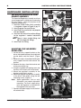
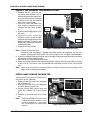
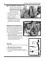
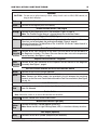
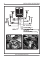
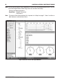
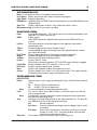
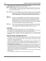
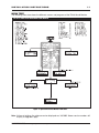
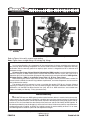
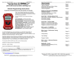
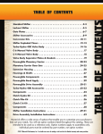
POWER HAS NEVER BEEN EASIER
Digital Propane Injection® for Ford 7.3L
'99-'03 Powerstroke Turbo Diesel Vehicles
PN 4810, U.S. Patent Pending
IMPORTANT: Be sure to read and understand all instructions before installation. Failure to do so may
lead to damage of property, injury and voiding of warranty.
Parts Included:
1 - Regulator Assembly
1 - Regulator Mounting Bracket
1 - Propane Lock-off Solenoid
1 - Fuel Pressure Switch
1 - 3-way Pressure Control Solenoid
1 - Propane Pressure Sensor with Fitting
1 - Boost Signal Hose
1 - Electronic Control Unit (ECU)
1 - Harness Assembly
1 - Monitor Cable
1 - Heater Hose
1 - Enable Switch
1 - Fault Light
1 - Vapor Hose
1 - Discharge Fitting, Elbow (Vapor to Intake)
2 - Fitting (Heater Hose to Vaporizer)
2 - Parts Bag
1 - MSD Pro Data+ CD, PN 9608
WARNING: Disconnect the batteries during installation of the DPI® system. When disconnecting
the batteries, remove both negative battery cables first and install them last.
Note: The propane tank must be purchased separately and must meet Federal DOT and NFPA 58
requirements as well as state and local requirements that may apply. Information is available
from your local propane professional which can be located at www.usepropane.com.
LIQUID PROPANE REQUIRED
The DPI system requires liquid propane at the
regulator to function correctly. IT WILL NOT
work on propane vapor. The tanks must be
equipped with a liquid pickup. Be aware that
some tanks only offer a vapor fitting.
CAUTION: Propane is heavier than air and will settle in low laying areas. Propane vaporizes at
–40° Fahrenheit and will freeze items if contacted.
Note: The addition of propane will increase the exhaust gas temperatures. It is recommended to install
an exhaust pyrometer to monitor these temperatures and ensure they stay within a safe level.
Note: Consult your vehicle's owner's manual in regards to vehicle/powertrain warranty programs
whenever adding aftermarket performance products.
Note: Apply proper amount of pipe thread sealant on all fittings.
Note: If your 1999 model truck has a build date prior to December 1998, there will be some installation
differences. Please contact MSD for information on where to mount the DPI Regulator assembly
and how to obtain an rpm signal.
SUPERCHIPS • www.superchips.com • 1790 Airport Blvd. • Sanford, FL 32773 • (407) 585-7000 • FAX (407) 585-1900
INSTALLATION INSTRUCTIONS
HARDWARE INSTALLATION
Vaporizer/Regulator Component Assembly
The Vaporizer/Regulator assembly must have
some components installed prior to mounting
the unit. Figure 1 shows the location of the
supplied components.
1. Install the Outlet Orifice. Verify assembly
is inserted as shown in Figure 12 pg. 12.
2. Install Propane Pressure Sensor.
3. Install Fuel Pressure Switch and propane
lock-off solenoid.
4. Install the 90° coolant hose elbow fittings
to the regulator’s coolant inlet/outlet
ports.
Note: Figure 1 shows straight fittings, but
the kit includes 90° fittings.
5. Install Fuel Line Fitting.
Mounting the Vaporizer/
Regulator
1. Locate the relay support bracket on the
driver side fender between the windshield
washer bottle and the firewall. (Figure
2).
2. Remove the 6mm thread bolt holding the
relay support bracket and remove the
bracket.
3. Remove the relays from the bracket and
tie them out of the way.
4. Using the supplied self-tapping screw, tap
the boss in the lower part of the fender.
5. Mount the regulator assembly to the
bracket so the inlet is on top.
6. Mount the regulator and bracket assembly
to the driver side fender using the two
mounting screws (Figure 3).
Note: Some applications, such as early
'98 models, may require alternative
mounting. For these applications
verify the regulator is mounted with
the regulator inlet at the top.
7. Connect the liquid supply line to the lock
off solenoid inlet.
Propane
Lock-off
Solenoid
Fuel Line
Fitting
Fuel
Pressure
Switch
Coolant
Hose
Fitting
Outlet
Orifice
Pressure
Control
Solenoid
Coolant
Hose
Fitting
Boost
Pressure
Port
Boost
Pressure
Sensor
Mounting
Bracket
Bolts
Propane
Pressure
Sensor
Figure 1 Assembling the Vaporizer/Regulator.
Relays
and
Bracket
Remove
Figure 2 Relay Support Location.
Regulator
Bracket
Figure 3 Mounting the Regulator Assembly.
SUPERCHIPS • www.superchips.com • 1790 Airport Blvd. • Sanford, FL 32773 • (407) 585-7000 • FAX (407) 585-1900
INSTALLATION INSTRUCTIONS
Install the Propane Discharge FITTING
1. Remove the flex section of the
air intake tube between the air
cleaner outlet and the turbo inlet.
Use care not to allow any foreign
material to fall into the turbine
inlet or air cleaner outlet.
2. Drill a 3/4” hole in the tube in the
area shown in between the Air
Cleaner and the Turbo (Figure
4).
3. Insert the discharge fitting in the
3/4" hole.
4. From the inside, install the
concave washer to the threads
of the fuel discharge fitting so the
domed side faces the discharge
fitting and it aligns with the curve
of the intake tube.
5. Install flat washer and nut.
Air
Cleaner
Cotter
Pin
Turbo
Figure 4 Installing the Propane Discharge Fitting.
Note: Tighten so that washer is seated to tube and fitting is aligned with vapor hose from regulator. Do not over
torque. Coating with Red Loctite 272 or Blue Loctite 242 is highly recommended.
6. Insert the supplied cotter pin through the Discharge Fitting and bend the ends outward to
prevent the nut from coming loose.
7. Reinstall the air intake tube to the engine.
8. Route the Propane Vapor Hose from the Regulator Outlet to the Discharge Fitting. It needs
to be cut to fit. This hose is wire re-inforced and should be cut with cut-off saw or band
saw.
Note: Verify there are no kinks in the hose and it is routed a safe distance away from sharp edges and hot engine components.
InstalL MAP SENSOR Vacuum Tee
You must tee in a map sensor line that runs
the sensor on the Vaporizer.
1. Route the new Pressure Hose along the
top of the firewall.
2. Insert the Pressure Hose in the Regulator
Assembly Boost Pressure Port.
3. Cut the factory MAP sensor hose and
install the supplied Tee in-line (Figure
5).
4. Connect a new pressure hose to the
tee.
Note: Verify the Manifold Pressure Hose
is not kinked and is routed in a safe,
secure manner that is away from
any sharp objects or engine heat
sources.
Sensor
Location
Line to
Vaporizer
Figure 5 Connecting the MAP Sensor.
SUPERCHIPS • www.superchips.com • 1790 Airport Blvd. • Sanford, FL 32773 • (407) 585-7000 • FAX (407) 585-1900
INSTALLATION INSTRUCTIONS
➙
Note: The Vaporizer assembly
requires a constant flow of
engine coolant to maintain
proper propane flow. Use the
manufacturer recommended
coolant. See your Owner’s
Manual for information.
1. Remove the 3/8" hose from the
driver side of the surge tank.
2. Cut hose in kit to install "T" fitting
as shown in Figure 6.
3. Route a new hose from the "T"
fitting to the vaporizer.
4. Route and clamp a new hose from
the vaporizer to the driver side
engine block, using the supplied
3/8" NPT fitting as shown in Figure
6.
➙
INSTALL Vaporizer Coolant Hose
Figure 6 Installing the Coolant Hoses.
MountING THE controller
The DPI’s ECU can be mounted in almost any
location and any position under the hood.
Mount away from high temperature sources,
such as exhaust manifold, as well as direct
pressure wash spray. Mounting it under the
dash is recommended (Figure 7).
1. Mount the controller under the driver side
of the dash, behind the removable panel
to access the fuse group.
2. Route the wiring harness through the
firewall. Find a suitable location or drill a
hole to route the wires through. Use care
not to cut or damage the wires. Also, use
a grommet to insulate the wiring.
Parking
Brake
Figure 7 Mounting the ECU.
WIRE TO BE
SPLICED
BARREL
MALE
ENDCUP
WIRE TAP
1. Insert Male End Cup into wire to be spliced (Figure
8).
2. Apply Silicone Sealant in Barrel end.
3. Hand tighten Barrel into Male End Cup.
4. Strip wire approximately 3/8” (10mm).
5. Insert wire into Male End exposing only bare wire.
6. Hand tighten male end to Barrel. Connection
complete!
3/8”
(10 mm)
MALE
END
Figure 8 Using a Wire Tap.
SUPERCHIPS • www.superchips.com • 1790 Airport Blvd. • Sanford, FL 32773 • (407) 585-7000 • FAX (407) 585-1900
INSTALLATION INSTRUCTIONS
WIRING
CAUTION: Do not cut or splice into any critical safety circuits such as ABS, SRS control (air
bag) or dash displays.
Red
Connect to the Fused Key On power source (10 Amp minimum).
Black
Connect to the negative post of the battery.
Throttle Position Sensor (TPS) Signal
Orange
Connect to Gray/White wire of the TPS connector (Figure 9, page 6).
Note: The Throttle Position Sensor is located above the Accelerator Pedal.
Trigger Wire (RPM) Signal
White
Connect to the Light Green/White wire that is grouped with a Red, White and Blue wire.
The wires are located above the parking brake pedal (Figure 9, page 6).
Alternate Connection: To White/Pink on Pin 19 of ECU. (On Driver's side of firewall in
the engine compartment.)
Boost Pressure Sensor
4-Pin
Connector
w/3 Wires
Connect to the 4-pin connector of the Boost Pressure Sensor on the Red block of
the Regulator Assembly. (This Boost Pressure Sensor does not use the temperature
sensor function). See Figure 1, page 2.
Propane Pressure Sensor – Regulator
4-Pin
Connector
w/4 Wires
Connect to the 4-pin connector on the Propane Pressure Sensor on the Regulator
Assembly. See Figure 1, page 2.
Pressure Control Solenoid and Pressure Protection Switch
Green
Connect to the Pressure Control Solenoid.
White
Connect to either side of the Fuel Pressure Switch.
Note: Connect the White jumper wire provided in the kit between the remaining
contacts on the Pressure Control Solenoid and the Fuel Pressure Switch (See Figure
13, pg. 12).
Lock Off Solenoid
Yellow
Red
Connect these sleeved wires to the 2-pin Weather Pack connector on the Propane
Lock Off Solenoid.
Enable Switch
Note: Mount the switch in an accessible location for the driver.
Pink/Red Connect sleeved wires to the Enable switch.
Malfunction Indicator Light (MIL)
Brown/
White
Red
Connect to the wires sleeved together to the LED.
Note: Mount the MIL or Light Emitting Diode (LED) in a location visible by the driver.
Tach Output (Optional)
Gray
Connects to tach for 4-cylinder (two pulses per revolution).
SUPERCHIPS • www.superchips.com • 1790 Airport Blvd. • Sanford, FL 32773 • (407) 585-7000 • FAX (407) 585-1900
INSTALLATION INSTRUCTIONS
DIGITAL PROPANE INJECTION
WWW.SUPERCHIPS.COM
Orange
DPI
Wire
LT. GREEN/
WHITE WIRE TO
DPI WHITE
Gray/White
Wire
TPS
Gas
Pedal
Throttle Position Sensor
Parking
Brake
Trigger Wire Location
Figure 9 Wiring the Digital Propane System.
SUPERCHIPS • www.superchips.com • 1790 Airport Blvd. • Sanford, FL 32773 • (407) 585-7000 • FAX (407) 585-1900
INSTALLATION INSTRUCTIONS
PROPANE DELIVERY and LEAK TEST
• It is recommended to have the propane tank filled by a qualified supply service and have
them verify that there are no leaks in the system.
• The DPI Controller will not activate the LP Lock-Off Solenoid until all conditions are detected
and meet program requirements: Engine RPM, Throttle Position, Intake Manifold Pressure
(Boost) and System Request (On/Off).
• Temporarily connect the LP Lock-Off Solenoid to +12v and Ground.
• Verify no leaks are present outside of regulator assembly.
CAUTION: If a leak is detected, shut the fuel tank off immediately. Repair leaks if necessary, and
repeat test/repair until no leaks are detected.
Connect LP Lock-Off Solenoid to ECU harness.
SYSTEM OPERATION TEST
• The DPI system comes fully programmed and ready to run without using a computer. You
only need to connect a computer if you wish to monitor the DPI system operation, or to
change programmable features. It is recommended to start and test drive the vehicle before
making any changes to the software.
Programming and Acquisition Information
for the Superchips DPI Pro-Data+/Graphview
Software
System Requirements: Windows 95 or later.
Software: MSD Graphview/Pro-Data+ software.
Connect the monitor cable included in the kit (This is a standard 9 Pin Serial cable (DB9) from
the RS-232 connector on the DPI ECU to a serial port on the PC).
INSTALLATION of the Pro-Data+ Software
1. Insert CD Rom.
2. Click on version of Software you want to install from the MSD Ignition Pro-Data
menu screen.
3. Follow steps to load software.
4. Click on MSD Graph View Icon.
5. Click on File, then Open.
6. Click on the 4810 folder, then click on 4810v##.ign (## determines the version,
such as 05).
7. Turn Ignition power On.
SUPERCHIPS • www.superchips.com • 1790 Airport Blvd. • Sanford, FL 32773 • (407) 585-7000 • FAX (407) 585-1900
INSTALLATION INSTRUCTIONS
Note: Do not cycle the ignition switch repeatedly or leave on for an extended period of time. This can
cause the Engine Heaters/Glow Plugs to turn on and drain the battery.
Observe the following windows:
GraphView: Product Connected
Data Source
Note: File name will be displayed when file is opened as in Step 6 on page 7. “None” on either or
both indicates communication failure.
Figure 10 Pro-Data+ Screen and Program Windows.
SUPERCHIPS • www.superchips.com • 1790 Airport Blvd. • Sanford, FL 32773 • (407) 585-7000 • FAX (407) 585-1900
INSTALLATION INSTRUCTIONS
Data monitor list
Note: List will be blank if there is no product communication.
User Notes: Allows you to enter notes and save with each program.
Data Editor: Programmable items
RPM Meter: Graphical display of RPM, Propane Operating Pressure and Manifold Pressure
(Engine Boost).
Alert List: Displays notifications of alerts. Only visible when Alert is active.
Maintenance Log: Lists the last nine alerts recorded.
MOnitored items
Pwm:
RPM:
LpPsia:
TPS In:
TPS %:
Fuel Temp: MapIn:
AcqRun:
Lp Sys: Liquid Sol:
PwrLevel:
Baro:
Cruise:
Pulse Width Modulation, “ON” time for the Pressure Control Solenoid on the regulator. This varies from 0 to 255.
Engine speed
Verify RPM displayed is approximately equal to vehicle RPM on Tach or scanner.
The measured pressure of the propane in the regulator, measured in absolute pressure.
Throttle Position Sensor signal. Range: 0-1023
Converted TPS In signal increasing value from approximately 0 at idle to near 100 at full throttle.
Displays the temperature of the propane at outlet of regulator.
Manifold Absolute Pressure in the engine intake manifold.
Status of the DPI data recording system.
System ON/OFF switch
Verify display alternates between OFF & ACTIVE when switched is toggled.
Displays whether Lock OFF solenoid is “ON” or “OFF”.
Displays setting of power level selected.
Displays the recorded ambient atmospheric pressure.
Displays whether the system is in cruise control mode. This mode simulates Throttle Position based on engine manifold pressure.
PROGRAMMABLE ITEMS
DATA EDITOR
Pedal:
The two values set the range for reading the factory Throttle Position Sensor (TPS).
Lo: Displays TPS In at idle/minimum.
Hi:
Displays TPS In fully depressed.
Note:
It is recommended to use pre-programmed values.
Fuel:
This value is factory set at 100 (for 100%) so that the system runs the fuel map as programmed.
Note:
Changing this value will reduce the amount of propane sent to the engine over the entire operating range.
Acq:
Setting the start and length of time for the data acquisition file. The data file has 2000 points that may be spread out over time.
Off: No data acquired.
Run once: One time window of data begins when the toggle (Lp Sys) switch is turned on.
Run loop: Data is taken continuously, and when saved, the last record window is saved. This is a traveling window, with new data continuously replacing the oldest.
Run alert:
One window of data is taken only when an alert flag is set.
SUPERCHIPS • www.superchips.com • 1790 Airport Blvd. • Sanford, FL 32773 • (407) 585-7000 • FAX (407) 585-1900
10
INSTALLATION INSTRUCTIONS
Note: THESE DATA FILES ARE NOT AUTOMATICALLY SAVED!
Select a length of time: 20 sec., 80 sec., 6 min., 33 min.
Note: Shorter file lengths have faster sample rates which give better definition to the data lines and will better show what happens before, during, and after a particular event such as a transmission shift.
Boost enable:This is the manifold pressure at which the lp system will activate. The default setting is zero so that the propane system will begin to inject propane during normal driving conditions. If so desired, the boost enable value may be raised so that propane is only injected during acceleration and hill climbing.
Extend
Boost limit:
This value is the manifold pressure above which propane injection will be disabled. The default setting is 45 psi, which is the maximum of the factory supplied sensor. This value may be lowered to correspond to the vehicle maximum boost level. If the value is raised above 42 psi, the pressure sensor will not be able to send a value this high to the computer, therefore, propane will not be disabled due to overly high manifold pressure.
RPM limit:
The maximum engine rpm up to which propane will be injected. The default value is set for each motor type, based on the factory limits. If the rpm value is raised, propane will continue to be injected up to the new value.
save data
• In the “GraphView MSD file” window, go to “view”, click on “Run History”.
• In the “Run History” window, go to the “Transfer”, Click on “Acq to plot”. This will store the
last window (as set in the data editor menu) of data from the DPI to the PC.
• To save the data file, go into the “Run History” window, go to the “File” pull down menu,
click on “Save Acq as” and either use the name supplied, or enter in a new name, and click
on “Save”.
view previously recorded data file
• Open the “Graphview File” MSD window, go to “View” pull down menu, and click
on “history1”. In the “file” pull down menu, click on “Open Acq” and select a file.
• To display the values in the graph, go to “View”. Pull down menu in the “history1” window,
and click on “Tracebox/Analysis” Box.
• As the cursor is moved across the window, a vertical black line moves along with it, and the
values of lines where they cross the vertical black line are displayed in the trace box.
• The lines of data in the “history1” window may be turned on and off by clicking the “x” next
to the data name in the trace box.
• Time between events may be displayed by moving the vertical black line (either with the cursor
or the left/right arrow keys) to the first event and hitting the spacebar on the keyboard.
• This will mark that location with a red line. Move the black line away from that point, and the
time between the red and black lines will be displayed at the top of the “history1” window.
Press the space bar again to remove the red marker.
• Multiple files may be opened in the same window, and all the lines of data will be displayed
in the trace box.
• The same data line in different files will have the same color in all files.
SUPERCHIPS • www.superchips.com • 1790 Airport Blvd. • Sanford, FL 32773 • (407) 585-7000 • FAX (407) 585-1900
INSTALLATION INSTRUCTIONS
11
Menu Tree
The following menu tree shows the different screens and programs of the PN 4810 and Monitor.
PN 4810 Flow Chat with Hand Held Monitor
Figure 11 Optional Hand Held Monitor Flow Chart.
Note: At time of printing, the software version displayed was V05 M05. Newer version numbers will
display as upgrades apply.
SUPERCHIPS • www.superchips.com • 1790 Airport Blvd. • Sanford, FL 32773 • (407) 585-7000 • FAX (407) 585-1900
POWER HAS NEVER BEEN EASIER
IN
Figure 12 Outlet Orifice
Assembly
OUT
WHITE
JUMPER
WIRE
Figure 13 Vacuum Line Routing.
Refer to Figure 13 to verify vacuum hose routing.
Note: Figure shows straight fittings. Kit includes 90° fittings.
Service
In case of malfunction, this component will be repaired free of charge according to the terms of
the warranty. When returning components for service, Proof of Purchase must be supplied for warranty
verification. After the warranty period has expired, repair service is charged based on a minimum and
maximum charge.
All returns must have a Return Material Authorization (RMA) number issued to them before being
returned. To obtain an RMA number please contact MSD Customer Service at (915) 855-7123 or fax a
request to (915) 857-3344. Send the unit prepaid with proof of purchase to the attention of: MSD Ignition,
Customer Service - RMA #, 12120 Esther Lama, Suite 114, El Paso, Texas 79936.
When returning the unit for repair, leave all wires at the length in which you have them installed. Be
sure to include a detailed account of any problems experienced, and what components and accessories
are installed on the vehicle.
The repaired unit will be returned as soon as possible after receipt, COD for any charges. (Ground
shipping is covered by warranty). All units are returned regular UPS unless otherwise noted. For more
information, call the MSD Customer Service Line (915) 855-7123. MSD technicians are available from
7:00 a.m. to 6:00 p.m. Monday - Friday (mountain time).
M
Limited Warranty
SD IGNITION warrants MSD Ignition products to be free from defects in material and workmanship
under normal use and if properly installed for a period of one year from date of purchase. If found to be
defective as mentioned above, it will be replaced or repaired if returned prepaid along with proof of date of
purchase. This shall constitute the sole remedy of the purchaser and the sole liability of MSD Ignition. To
the extent permitted by law, the foregoing is exclusive and in lieu of all other warranties or representations
whether expressed or implied, including any implied warranty of merchantability or fitness. In no event
shall MSD Ignition be liable for special or consequential damages.
SUPERCHIPS • www.superchips.com • 1790 Airport Blvd. • Sanford, FL 32773 • (407) 585-7000 • FAX (407) 585-1900
FRM27143
© 2005 Superchips, Inc.
Created 11/05
Printed In U.S.A.