1
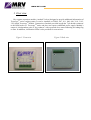
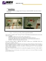
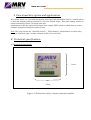
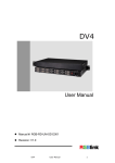
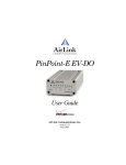
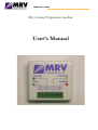
www.mrv.com
Dry Contact Expansion module
User’s Manual
www.mrv.com
Table of Contents
1..Overview
2. Installation
3. Functional description and applications
4. Technical specifications
5. Warranty
6. Standards
3
4
5
5
6
6
www.mrv.com
1. Overview
Dry contact expansion module (“module” below) designed to provide additional information-of
TerescopeTM units working status. It can be installed on TS802, 807, 811, 940, 960, 3101, 3103,
3303, 4400 TerescopeTM models. Connection of module provided trough the 7-pin header connector
to the RSM socket of TerescopeTM units, and does not requires additional power supply. Module’s
output is 4 independent pairs of “dry contacts” with open and close states indicating according flag
or state. In addition, 4 indication LEDs is also provided for convenience.
Figure 1. Front view
Figure 2. Back view
www.mrv.com
2. Installation
For installation Module is plugged in the TerescopeTM head at the RSM 7-pin socket as shown
On fig No.3
Figure 3. Installation of the dry contact expansion module
After insertion of module in the Terescopetm head it’s LED indicators should show the current state
of the next signals:
- “AIRLINK” LED shows the status of the Air link” flag Led.
- “DATA” LED shows the status of the “Electrical/Fiber interface link” Led.
- “LOW RSSI” LED indicates that actual RSSI is lower than determined threshold level,
- “POWER” LED shows the status of the power Led.
At normal working condition, “AIRLINK” and “DATA” LEDs are on, “LOW RSSI” LED is not
blinking and “POWER” LED is on.
For wires connection please use supplied 8-pin male plug connector (Phoenix Contact Company’s
MINI-COMBICON Plug MC 1,5/8-ST-3, 81 Cat. No 1803633). Wires should be 0.5-0.7 mm2 rigid
solid or flexible stranded (23-20 AWG). Screwdriver of blade type 0.4 x 2.5 x 80 mm should be
used for accurate connection.
Note: We recommend connecting all wires to plug before plugging it into the dry contact module’s
socket.
After installing all wires and checking dry contact module’s operation, close Terescope™ head ‘s cover back
and fix it with its screws.
www.mrv.com
3. Functional description and applications
Dry contact alarm is a convenient mechanism that relays link information back to a control station
or unit and instantly notifies personnel in case of a defined failure. This states change enables to
remote monitoring of basic TereScope unit state.
Applications for the dry contact relay ranges from a simple LED’s alarm or sound alarm to a more
complex computerized multi-activation system.
Note: The relay contacts are “Normally closed” (~ 15Ώ resistance), when alarm is set on the relay
switch to “Normally open” and the resistance will be OL (over load).
4. Technical specifications
4.1 Mechanical Dimensions:
51mm
55mm
Figure 4. Dimensions of dry contact expansion module
www.mrv.com
4.2. Electrical characteristics and weight:
Characteristics
I/O Isolation level
Isolation between channels
Contacts Rating
Peak load current
Operating temperature
Typical “ON” resistance
“Snabber” protector
Weight
Levels
3000 VAC RMS between contacts and all other
voltages
500 VAC RMS
350 VDC or AC Peak, 0.12 A MAX, 0.5W Max
0.4A 0.1sec. Max
–40°C to +70°C
25 Ohm, Max. 35 Ohm
200 Ohm resistor, 1nF/1500 VDC capacitor
50g
5. Warranty terms
This Dry contact module (product) is covered by guarantee against fabrication defects for a
period of 12 months from the date of purchase.
In case of any malfunction of the module, Optical Access will repair or replace it with new
product.
The postage/transportation costs of the product shipment from the Customer to Optical
Access are on the client’s account. The remittance expenses of the repaired/exchanged
product are on Optical Access account.
This warranty does not cover malfunctions or damages caused by improper handling,
unauthorized parts replacement or modifications, wrong use, or functioning in improper
environments as well as damages caused by atmospheric ESD discharges.
6. Standards Compliance
6.1 European Community EN55022 class B - EMI/RFI radiated emission class B.
6.2 FCC Rules, Part 15,subpart J, FCC Class B (Quasi Peak).
6.3 IEC 529: 1989 Degrees of protection provided by enclosures (IP Code): IP 65 (when
installed under the TereScope™ unit’s cover and a standard cable inlet flexible duct and
flange).