1
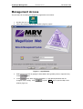
MegaVision
TereScope Management
User Guide
MRV Communications, Inc.
URL:
http://www.mrv.com
TereScope Management
ML48200, Rev. 01
December 2004
Disclaimer
®
MRV reserves the right to modify the management application for this device at any time and in any way it
sees fit in order to improve it.
MRV provides this document without any warranty of any kind, expressed or implied, including, but not
limited to, the implied warranties of merchantability or fitness for a particular purpose.
The user is advised to exercise due discretion in the use of the contents of this document since
the user bears sole responsibility.
Trademarks
All trademarks are the property of their respective holders.
Copyright © 2004 by MRV
All rights reserved. No part of this document may be reproduced without the prior permission of MRV.
This document and the information contained herein are proprietary to MRV and are furnished to the
recipient solely for use in operating, maintaining and repairing MRV equipment. The information within may
not be utilized for any purpose except as stated herein, and may not be disclosed to third parties without
written permission from MRV. MRV reserves the right to make changes to any technical specifications in
order to improve reliability, function, or design.
Document Number: ML48200
Document Revision: Rev. 01
Contact Information
For customer support, you can:
Contact your local MRV representative
E-mail us at [email protected]
Visit our MRV Web site at http://www.mrv.com
2
Release Date: November 2004
TereScope Management
ML48200, Rev. 01
December 2004
Contents
About this Guide ............................................................................... 5
Scope ..........................................................................................................................................5
Audience ....................................................................................................................................5
Related Documents ...................................................................................................................5
Organization...............................................................................................................................5
Typographical Conventions .....................................................................................................5
Acronyms ...................................................................................................................................6
TereScope Overview......................................................................... 7
General .......................................................................................................................................7
Requirements.............................................................................................................................7
SNMP Agent ...............................................................................................................................7
General...................................................................................................................................7
Models ....................................................................................................................................7
Layout.....................................................................................................................................8
Setup...........................................................................................................................................8
Cabling .......................................................................................................................................8
Management Access ........................................................................ 9
Management Setup ......................................................................... 11
Device Management ....................................................................... 19
Accessing the Management Window ....................................................................................19
General Device Parameters....................................................................................................20
Appendix A: IP Address Unknown............................................... 25
Appendix B: LLB and RLB Tests.................................................. 26
General .....................................................................................................................................26
LLB Test ...................................................................................................................................26
Purpose ................................................................................................................................26
Data Path..............................................................................................................................26
Procedure .............................................................................................................................26
3
TereScope Management
ML48200, Rev. 01
December 2004
RLB Test ...................................................................................................................................27
Purpose ................................................................................................................................27
Data Path..............................................................................................................................27
Procedure .............................................................................................................................27
Appendix C: Fusion Control..........................................................29
General .....................................................................................................................................29
Purpose ....................................................................................................................................29
Procedure .................................................................................................................................29
Figures
Figure 1: Straight and Cross Cable Wiring ..................................................................................... 7
Figure 2: Login Window .................................................................................................................. 9
Figure 3: Map Level Window ........................................................................................................ 10
Figure 4: Device Types Window................................................................................................... 11
Figure 5: Describe Device Communication Parameters Window ................................................ 12
Figure 6: Define Interface Window ............................................................................................... 13
Figure 7: DOS Command Window ............................................................................................... 14
Figure 8: TereScope Icon (Green) Added in Map Level Window................................................. 15
Figure 9: Device Parameters Configuration Window (showing TereScope default IP address).. 16
Figure 10: Device Parameters Configuration Window (showing TereScope new IP address) .... 17
Figure 11: Confirm Window .......................................................................................................... 18
Figure 13: Device Parameters Configuration Window ................................................................. 19
Figure 14: Data Path in LLB Test ................................................................................................. 26
Figure 15: Fusion Mode Configuration and Mode Select Status Con … Windows...................... 27
Figure 16: Data Path in RLB Test................................................................................................. 27
Tables
Table 1: Models of SNMP Agent .................................................................................................... 7
Table 2: DIP Switch Setting of TereScope ..................................................................................... 8
Table 3: General Device Parameters Fields and Tools................................................................ 20
Table 4: Communication Parameters Fields and Tools ............................................................... 21
Table 5: Thresholds Fields and Tools .......................................................................................... 23
4
TereScope Management
ML48200, Rev. 01
December 2004
About this Guide
Scope
This guide shows how to manage any of the series of TereScopes (e.g., TereScope 2,
TereScope 155, TereScope 2000, TereScope 4000, TereScope 5000) using MRV’s
MegaVision® network management application.
Audience
This guide is intended for the use of network administrators who have working knowledge of
SNMP management.
Related Documents
• MegaVision NMS Application User Manual
This manual describes how to install and use the MRV’s MegaVision NMS Application.
• MegaVision TereScope Release Notes
This document contains information not found in the User Guide and/or overriding
information, and is produced if warranted.
• TereScope Manual
This document contains information on the relevant TereScope to be managed.
Organization
For customer convenience, the management description is organized according to the service
architecture of the MegaVision Application GUI which is hierarchical.
Typographical Conventions
The typographical conventions used in this document are as follows:
Convention
Explanation
CourierBold
This typeface represents information provided by/to the system.
Italics
This typeface is used for emphasis.
Enter
This format represents the key name on the keyboard or keypad.
!
This icon represents important information.
This icon represents risk of personal injury, data loss, or system damage.
5
TereScope Management
ML48200, Rev. 01
Acronyms
ARP
Address Resolution Protocol
BER
Bit-Error Rate
CLI
Command Line Interpreter
CTS
Clear To Send
dB
deciBel
DCD
Data Carrier Detect
DCE
Data Communication Equipment
DNS
Domain Name System/Service
DSR
Data Set Ready
DTE
Data Terminal Equipment
DTR
Data Terminal Ready
Gnd
Ground
GUI
Graphical User Interface
IP
Internet Protocol
ITU
International Telecommunications Union
LLB
Local LoopBack
LAN
Local Area Network
MDI
Media Dependent Interface
MDI-X
Media Dependent Interface with cross-wiring
NIC
Network Interface Card
NMS
Network Management Station
OID
Object IDentifier
RARP
Reverse ARP
RI
Ring Ignore
RLB
Remote LoopBack
RMON
Remote MONitoring
RTS
Request To Send
RxD
Receive Data
SNMP
Simple Network-Management Protocol
TDM
Time-Division Multiplexer/Multiplexing
TELNET
(dial-up) TELephone NETwork (connection protocol)
TFTP
Trivial-File Transfer Protocol
TxD
UPS
URL
WAN
Transmit Data
Uninterruptible Power Supply
Universal Resource Location
Wide Area Network
6
December 2004
TereScope Management
ML48200, Rev. 01
December 2004
TereScope Overview
General
The TereScope is a communication link that can carry voice, data, and video transparently over a
photonic beam. The link consists, basically, of two heads, each containing a transceiver, and
facing each other so that the beam interconnects them. A wide range of models is available to
support various frequencies, operating ranges, and eye-safety compliance. There are models that
support data rates of up to 1 Gbps and operating ranges of up to 5 km.
Requirements
− SNMP NMS1 with a 10Base-T NIC/port and MS-DOS program.
− Category 5 cross cable (shown in Figure 1, page 7) not longer than 100 m or 328 ft if the
TereScope is to be connected to the SNMP NMS directly. (The SNMP NMS, e.g., PC is a
DTE.)
or
Category 5 straight cable (shown in Figure 1, page 7) not longer than 100 m or 328 ft if the
TereScope is to be connected to the SNMP NMS via a DCE (e.g., switch).
Figure 1: Straight and Cross Cable Wiring
SNMP Agent
General
A TereScope is SNMP manageable if it has an SNMP agent installed in each of its two heads. In
models 2000, 4000, and 5000 the SNMP agent is pre-installed. TereScopes in the field can have
the SNMP agent installed in them by an MRV-approved service person.
Models
Table 1 describes the available models of the SNMP agent for TereScope management.
Table 1: Models of SNMP Agent
Model
Description
RSM-SNMP
Installable in all TereScopes, except TereScopes 4000 and 5000.
SNMP-MGT
Installable in TereScopes 4000 and 5000. This SNMP agent model provides,
in addition, operation configurability, such as, Fusion and Loopback testing.
1
e.g., PC running MRV’s MegaVision® Web-based network management application.
7
TereScope Management
December 2004
ML48200, Rev. 01
Layout
Port
Protocol: Ethernet 10Base-T.
Connector: RJ45
Pinout: MDI (1 ! Tx+; 2 ! Tx-; 3 ! Rx+; 6 ! Rx-)
LEDs
Setup
Set the DIP switch toggles as shown in Table 2, page 8.
Table 2: DIP Switch Setting of TereScope
Toggle
IP configurability.
Position
ON
(To determine the right
toggle, refer to the
description of the toggle
on the TereScope.)
Function
Enable TereScope configuration (e.g., changing
default IP address of the SNMP agent) from the
SNMP NMS.
(The default IP address of the SNMP agent is
marked on a sticker on the rear panel of the
TereScope.)
OFF
Disable TereScope configuration from the SNMP
NMS, enable configuration at the TereScope head,
and set the IP address of the SNMP agent as
10.0.0.101.
Cabling
Connect the TereScope management port (RJ45 connector) to an SNMP NMS either:
− Directly with a Category 5 cross cable, or
− Via a DCE (e.g., switch) with a Category 5 straight cable.
8
TereScope Management
ML48200, Rev. 01
December 2004
Management Access
The procedure for accessing the MegaVision application is as follows:
.
1. Double-click the icon
2. Follow the prompts until the login window (Figure 2) opens.
Figure 2: Login Window
3. Select the access level by typing the associated name (possibly user or supervisor)
in the
4. In the
field.
field, either type the password or, if the default password was not
or press Enter key to open the Map Level
changed, leave it empty. Click
window (Figure 3).
9
TereScope Management
ML48200, Rev. 01
December 2004
Figure 3: Map Level Window
The hot spots and active areas that apply generically to devices are described in detail in the
MegaVision NMS Application User Manual.
The hot spot and active area that applies specifically to the TereScope is described below.
– Opens the TereScope Device Level management window.
Green – Communication with SNMP host OK.
Red – Communication with SNMP host lost.
10
TereScope Management
ML48200, Rev. 01
December 2004
Management Setup
In order to manage a TereScope, certain setup actions must be performed with the TereScope
and MegaVision application. In particular, these actions include setting IP addresses so that the
TereScope can be managed from the same or a different subnet.
The setup procedure is as follows:
1. Set the IP configurability DIP switch toggle to the ON position.
2. In the Map Level window (Figure 3, page 10), either click the button + (top left corner) or
click with the right mouse button and select Add Device. The Device Types window
(Figure 4, page 11) opens.
Figure 4: Device Types Window
3. In the Device Types window, select TSJ from the list.
4. The Describe Device Communication Parameters window (Figure 5, page 12)
opens.
11
TereScope Management
ML48200, Rev. 01
December 2004
Figure 5: Describe Device Communication Parameters Window
5. In the Describe Device Communication Parameters window:
a. Enter a name for the TereScope in the field Name and make sure that the entry in
the two fields Name for SET and Name for SET is public.
b. Click on the button Modify. The Define Interface window (Figure 6, page
13) opens.
12
TereScope Management
December 2004
ML48200, Rev. 01
Figure 6: Define Interface Window
6. In the Define Interface window, do the following:
a. Enter the default IP Address. (The default IP address – e.g., 10.0.0.150 – is
marked on a sticker on the rear panel of the TereScope).
b. Select Interface Type as Ethernet.
c.
Set Polling Interval
d. Set Time–Out
e. Set Retries
f.
Click
to close the window.
to
7. In the Describe Device Communication Parameters window, click
appears in the Map Level window (Figure
close the window. The TereScope icon
3, page 10).
8. If the SNMP NMS and TereScope are on different subnets, set a new static route in the
routing table of the router as follows:
a. Open MS-DOS Prompt window. (To open the window at the SNMP NMS which
runs a Microsoft Operating System, click
and select
When the Run window opens, type command and click
, type
b. At the DOS command prompt
route add [TS_IP_ADDR] mask
[MASK]
Where,
route, add, mask are keywords to be typed as is.
13
.
.)
[MGR_IP_ADDR]
TereScope Management
ML48200, Rev. 01
December 2004
[TS_IP_ADDR] is TereScope default IP address (marked on a sticker on
the rear panel of the TereScope).
[MASK] is Subnet Mask.
[MGR_IP_ADDR] is SNMP NMS IP address (e.g., PC’s IP address).
TereScope
default IP Address
Subnet
Mask
SNMP NMS
IP Address
Figure 7: DOS Command Window
9. Close the DOS Command window. The Map Level window (Figure 8) will show a green
icon of the TereScope
to indicate that its communication with the SNMP NMS is OK.
14
TereScope Management
ML48200, Rev. 01
December 2004
Figure 8: TereScope Icon (Green) Added in Map Level Window
10. Double-click on the icon
. The Device Parameters Configuration window
(Figure 9, page 16) opens. The field
shows the TereScope default IP address.
15
TereScope Management
December 2004
ML48200, Rev. 01
Figure 9: Device Parameters Configuration Window (showing TereScope default IP
address)
11. In the Device Parameters Configuration window:
a. In the field
, enter the new TereScope IP address. (The IP address is
usually one from the IP address space of your network.)
b. In the field
c.
, select one of the following:
−
LAN_Mode if the TereScope and SNMP NMS are connected to the same
IP network.
−
Router_Mode if the TereScope and SNMP NMS are interconnected via
a router.
If Router_Mode was selected, in the field
d. Press
, enter the Gateway address.
. (The window closes.)
12. Click on the button Parameters Config to reopen the Device Parameters
Configuration window (Figure 10, page 17), and verify that the IP settings are OK.
16
TereScope Management
December 2004
ML48200, Rev. 01
Figure 10: Device Parameters Configuration Window (showing TereScope new IP address)
13. Click the button Reset Device to reset the TereScope. When the Confirm window
(Figure 11, page 18) opens, press the button
17
.
TereScope Management
ML48200, Rev. 01
December 2004
Figure 11: Confirm Window
The communication icon
turns into
to indicate that communication is currently
broken since the TereScope is undergoing reset. At the end of the reset process, the
indicating that communication has been reestablished
communication icon reverts to
and that the TereScope is operating with its new IP address.
18
TereScope Management
December 2004
ML48200, Rev. 01
Device Management
Accessing the Management Window
This section shows how to monitor, configure, and control the TereScope remotely.
Open the Device Parameters Configuration window (Figure 12, page 19).
(This window can be opened in one of the following ways:
Way 1
In the Map Level window (Figure 8, page 15), double-click on the icon
.
Way 2
In the MegaVision Main Menu window, click on the menu button Monitor or Network and select
the item Devices List/Network Inventory... and click. A window with the list of all
devices is opened. Double-click on the row TSJ.)
Figure 12: Device Parameters Configuration Window
19
TereScope Management
December 2004
ML48200, Rev. 01
General Device Parameters
Table 3: General Device Parameters Fields and Tools
No.
Field/Tool
Function
1
Type of TereScope.
2
MAC address of the TereScope SNMP agent.
3
IP address of the TereScope SNMP agent.
4
Communication mode. The options are:
TereScope is set to assume that it is on the
same network as that of the SNMP NMS.
TereScope is set to assume that it is
connected to the SNMP NMS via a router.
5
Gateway IP address.
6
The version of the firmware of the SNMP Agent of the
TereScope.
7
The version of the hardware of the SNMP Agent of the
TereScope.
8
Type of SNMP NMS port (e.g., 10Base-T Ethernet).
9
Type of data port connected to the device at the end of
the TereScope link, e.g., MultiMode fiber, 1310 nm
operating wavelength, and 155 Mbps operating speed.
10
Set the IP Address, Communication Mode, and Gateway.
The choices for Communication Mode are:
TereScope and SNMP NMS are connected to the same
IP network.
TereScope and SNMP NMS are interconnected via a
router.
11
Update display from the database of the TereScope.
12
Ignore the changes in the window and close it.
(Opens the confirm window shown in Figure 11, page
18.)
20
TereScope Management
December 2004
ML48200, Rev. 01
Table 4: Communication Parameters Fields and Tools
No.
Field/Tool
Function
1
SNMP Communication OK.
2
No SNMP Communication.
3
(or
)
SNMP Agent link to switch side.
(Green-ON LED)
Link OK
(Red-ON LED)
Link Faulty
SNMP Agent link to air link (photonic beam).
4
Link OK
Link Faulty
5
The TereScope can be configured from the SNMP
NMS, i.e., DIP switch toggle for IP configuration is
set to ON position.
6
The TereScope can be configured only by locally
and physically changing its settings, i.e., DIP
switch toggle for IP configuration is set to OFF
position.
7
TereScope set to operate normally.
TereScope set to operate Local
LoopBack mode.
TereScope set to operate
Remote LoopBack mode.
8
(This tool is activated when Fusion
Mode is disabled.)
Open the Mode Select Status Con...
window:
The window fields/tools are:
TereScope to operate normally.
TereScope to operate in Local
LoopBack mode.
TereScope to operate in
21
TereScope Management
December 2004
ML48200, Rev. 01
Remote LoopBack mode.
Accept the changes in the window and
close it.
Ignore the changes in the window
and close it.
9
(Grey LED)
Fusion (redundant link) disabled.
(Green LED)
Fusion active; low RSSI at one end of link.
(Black LED)
Fusion in standby; RSSI OK.
10
Fusion mode enabled.
Fusion mode disabled.
11
Open Fusion Mode Configuration window:
The window fields/tools are:
Deselect Fusion Mode
Select Fusion Mode
Accept the changes in the window and
close it.
Ignore the changes in the window
and close it
22
TereScope Management
December 2004
ML48200, Rev. 01
Table 5: Thresholds Fields and Tools
No.
Field/Tool
Function
1
Close the window.
2
Open the Threshold Configuration window.
The window fields/tools are:
Set the lower and upper thresholds which if crossed
can generate an alarm or trap.
Lower threshold
Upper threshold
Strength of the signal at the
receiver (RSSI) (in millivolts).
Bias on the receiver (in volts).
(For factory use.)
Threshold temperature (in oC or oK). for
TereScope
Temperature threshold values can be set only if oK is
selected as the unit of measurement.
3
The actual strength of the RSSI signal at the receiver
(in millivolts).
4
The actual bias on the receiver (in volts).
(For factory use.)
5
The actual TereScope temperature (in oC or oK).
6
under
to get
will
Clicking the check box
display a speedometer chart for the row (Rx Signal
Strength (RSSI), Bias, or Temperature). This chart
displays the instantaneous value at the end of the
polling interval.
under
to get
will
Clicking the check box
displa a line chart for the ro (R Signal Strength
23
TereScope Management
ML48200, Rev. 01
December 2004
display a line chart for the row (Rx Signal Strength
(RSSI), Bias, or Temperature). This chart displays the
values at times that are integral multiples of the polling
interval.
7
Threshold values using
.
Lower threshold
Upper threshold
8
Start logging the RSSI, bias on the signal,
temperature, etc. in the log file.
9
TereScope Status Information Collection Interval. The
value 0 means that data will not be logged.
Any value in the range 1 to 300 (seconds) may be set.
If a value larger than the polling interval is to be
selected, it should be an integral multiple of the polling
interval for the purpose of synchronization. If a value
smaller than the MegaVision’s polling interval is
selected, data will be logged at times that are multiples
of the polling interval.
10
TereScope Status Information Collection File
tsj.log. Clicking a check mark in the check box
will visually emphasize
this field.
The file can store up to 15,000 entries. When the file
becomes full, its contents replace the contents of the
tsj.bak file, which can also store up to 15,000
entries. This means that up to 30,000 newest entries
can be stored in the two files. In order not to lose
entries, the tsj.bak file must be copied to another
file before the tsj.log file becomes full.
11
Accept value in TereScope Status Information
Collection Interval field
24
.
TereScope Management
ML48200, Rev. 01
December 2004
Appendix A: IP Address Unknown
This appendix describes the procedure for setting the IP address for a TereScope in the event
that the IP address is no longer known (for whatever reason).
1. Set the IP configurability DIP switch toggle to the OFF position. (In this position, the IP
address of the TereScope is 10.0.0.101.)
2. In the procedure described in the section Management Setup (page 11), perform steps 2
to 5.
3. In step 6 set the IP address to 10.0.0.101.
4. Perform steps 7 and 9.
5. Set the IP configurability DIP switch toggle to the ON position.
6. Perform steps 10 to 13.
7. Verify that the new IP has been accepted.
25
TereScope Management
December 2004
ML48200, Rev. 01
Appendix B: LLB and RLB Tests
General
This appendix applies only for SNMP Agent model SNMP-MGT, described in Table 1, page 7.
LLB Test
Purpose
The LLB test is used to determine whether the local TereScope head’s electro-optical circuitry is
OK.
Data Path
The data path (round-trip) in an LLB test is shown schematically in below. (The remote
TereScope head is not used in the LLB test.)
Figure 13: Data Path in LLB Test
Procedure
LLB can be performed by hardware or software control. The procedure for performing LLB by
hardware control is described in the relevant TereScope manual.
The procedure for performing LLB by software control is as follows.
1. Ensure that the Control Mode DIP switch toggle is set to the ON (SW MODE) position.
is dimmed, i.e., it is disabled, click on
in the same row as
2. If
The window Fusion Mode Configuration (Figure 14, page 27) opens. Set
and click
.
in the same row as
3. Click on
Status Con... (Figure 14, page 27) opens.
4. Set
and click
.
26
. The window Mode Select
.
TereScope Management
December 2004
ML48200, Rev. 01
Figure 14: Fusion Mode Configuration and Mode Select Status Con … Windows
RLB Test
Purpose
The RLB test is used to determine whether the local TereScope head, WDM cabling connected to
it, and remote TereScope head’s air link interface are OK.
Data Path
The data path (roundtrip) in an RLB test is shown schematically in below.
Figure 15: Data Path in RLB Test
Procedure
RLB can be performed by hardware or software control. The procedure for performing RLB by
hardware control is described in the relevant TereScope manual.
The procedure for performing RLB by software control is as follows.
1. Ensure that the Control Mode DIP switch toggle is set to the ON (SW MODE) position.
is dimmed, i.e., it is disabled, click on
in the same row as
2. If
The window Fusion Mode Configuration (Figure 14, page 27) opens. Set
and click
.
in the same row as
3. Click on
Status Con... (Figure 14, page 27) opens.
4. Set
and click
.
27
. The window Mode Select
.
TereScope Management
ML48200, Rev. 01
December 2004
Note
When RLB mode is set, the SNMP NMS is included in the RLB loop. An
NMS outside the RLB loop cannot be used to exit the RLB mode.
28
TereScope Management
ML48200, Rev. 01
December 2004
Appendix C: Fusion Control
General
This appendix applies only for SNMP Agent model SNMP-MGT, described in Table 1, page 7.
Purpose
MRV’s Fusion system, in full redundancy mode, activates a radiowave link when the IR laser link
of the TereScope fails so that the TereScope continues to operate as if the failure did not occur.
The Fusion system is constructed to maximize availability to 99.999% between network nodes
and operates in most weather conditions including rain, snow, and fog.
Procedure
Fusion can be performed by hardware or software control. The procedure for performing Fusion
by hardware control is described in the relevant TereScope manual.
The procedure for performing Fusion by software control is as follows.
1. Ensure that the Control Mode DIP switch toggle is set to the ON (SW MODE) position.
is dimmed, i.e., it is disabled, click on
in the same row as
2. If
The window Fusion Mode Configuration (Figure 14, page 27) opens. Set
and click
.
29
.