1
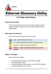
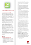
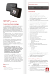
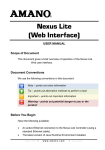
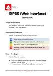
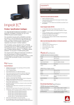
IXP220 Software QUICK START GUIDE Scope of Document This document gives a brief overview of the IXP220 System. Document Conventions We use the following conventions in this document: Note – points out extra information Tip – points out alternative methods to perform a task Important – points out important information Warning – points out potential danger to you or the product Before You Begin Have the following available: An active Ethernet connection to the IXP220 Controller. The IXP220 Software Suite. The MAC Address and Fixed Address of each IXP220 Controller – on a label bundled with the Controller. 1 Installation IXP220 Software Installation Procedure Install the IXP220 Software Suite on a single Host PC as follows: 1. Insert the IXP220 Installation CD into the CD-ROM drive. 2. Select the Install IXP220 Suite option. If the CD does not start up automatically, browse the CD in Windows® Explorer and double-click Setup.exe. 3. Select English as the language option. 4. Click the OK button. If no Database Server is present, one is installed. Follow the onscreen instructions for this. 5. At the Introduction screen, click Next. 6. At the Licence Agreement screen, select the I Accept the Terms of the Licence Agreement radio button. 7. Click the Next button. 8. At the Choose Install Folder screen, click Next. If you change the installation directory file path, ensure that you enter text only, NO spaces. Figure 1 – Install Set Menu ISW302-0-0-GB-00 March 2009 Page 2 9. At the Choose Install Set screen, from the Install Set drop-down list, make your preferred installation type selection. An Install Set is a collection of pre-selected applications suitable for specific scenarios. Customize an Install Set option by selecting or de-selecting applications from the list. 10. Click the Next button. 11. Click the Install button. 12. At the Install Complete dialog, click the Done button. By default Windows® XP (SP2 and SP3) installs a firewall. To keep this Firewall, unblock the TCP Ports thereby allowing functionality of the IXP220 Software. Continue as follows: 1. Select Start>Control Panel. 2. Select the Windows Firewall icon. 3. In the Windows Firewall Settings dialog, select the Exceptions tab. 4. Click on the Add Port button. 5. Unblock the TCP Port in the Add a Port dialog, by completing the Name (for example Impro) and Port Number (Ethernet Controllers use 10005) text boxes. 6. Select the TCP radio button. 7. Close the Add a Port dialog, by clicking the OK button. 8. At the Windows Firewall Settings dialog, again click on the Add Port button. 9. Set the Ethernet Firebird Port by completing the Name (for example Firebird Service) and Port Number (Ethernet communication uses 3050). 10. Select the TCP radio button. 11. Close the Add a Port dialog, by clicking the OK button. 12. Close the Windows Firewall Settings dialog, by clicking the OK button. ISW302-0-0-GB-00 March 2009 Page 3 Installing the Firebird 2.1 Database Server A Database Server is required to host the IXP220 Database. If the IXP220 Suite is installed on to a single PC, the Database Server installs automatically. However, if more than one PC is used to host the IXP220 Software, you must install the Database Server manually. Firebird automatically prompts to install, if a previous version is not detected. 1. 2. 3. 4. 5. 6. As any PC on the network can host the Database Server, select a PC to host the Database Server. Insert the IXP220 Installation CD in the PC’s CD-ROM drive. Browse to the \database\firebird directory on the IXP220 Installation CD. Double-click Firebird.exe. In the Select Language Setup dialog, from the drop-down menu, select your preferred language. Click the OK button. Firebird Installation Wizard 1. At the Welcome dialog, review and follow the on-screen instructions. 2. Click the Next button. 3. At the Licence Agreement dialog, select the I Accept the Agreement radio button. 4. Click the Next button. 5. Review the Information dialog, and then click the Next button. 6. In the Select Destination Location dialog, select the Destination Directory—we recommend that you use the default location of C:\Program Files\Firebird\Firebird_2_1. 7. Click the Next button. 8. From the drop-down menu, select the Full Installation of Super Server and Development Tools option. 9. At the Select Start Menu Folder screen click Next. ISW302-0-0-GB-00 March 2009 Page 4 Figure 2 – Firebird Select Additional Tasks 10. On the Select Additional Tasks screen: Select the Use the Guardian to Control the Server? option. Select the Run as a Service? option. Select the Start Firebird Automatically Everytime You Boot Up? option. Select the ―Install Control Panel Applet?‖ option. Select the Copy Firebird Client Library to <System> Directory? option. Select the Generate Client Library as GDS32.DLL for Legacy app. Support? option. 11. Click the Next button. 12. Click the Install button. 13. Review the Information dialog and then click the Next button. 14. Click the Finish button. ISW302-0-0-GB-00 March 2009 Page 5 Installing the USB Registration Interface’s USB Driver IXP220 uses a USB Registration Reader Interface to read Tags. Some Interface versions also provide an RS485 communication link to the Controllers. To install the driver, proceed as follows: If there are old USB Drivers on the PC, delete them before installing the provided driver. On some PC’s, the New Hardware Found wizard displays every time you plug in a USB Registration Reader Interface with a new USB Serial Number (Fixed Address). If this happens, choose the option to automatically install the unit. The New Hardware Found wizard will not display again. 1. Plug the USB Registration Interface into a USB port on the PC. The Found New Hardware Wizard displays. 2. Select the Locate and Install Driver Software (Recommended) option. 3. Select I don’t have the Disk. Show me Other Options. 4. Select the Browse My Computer for Driver Software (Advanced) option. 5. Click the Browse button. 6. In the Browse for Folder dialog, select the IXP220\USB_Device _Driver folder. 7. Click the OK button. 8. Click the Next button. 9. At the Windows Security dialog, select the Install this Driver Software Anyway option. 10. Click the Close button. You will notice that the Wizard pops up twice, installing two drivers; one for the USB Registration Reader and one for the COM Port to USB Bridge. ISW302-0-0-GB-00 March 2009 Page 6 2 Pre-configuration Procedure When all IXP220 Software components are installed, you need to perform the Pre-configuration Procedure. This procedure determines if the hardware communication infrastructure is functioning correctly. RS485 Communications Infrastructure 1. 2. Using the supplied USB Cable, connect the ImproX RS to the PC. Using the IXP220 Controller’s RS485 Controller Port, connect the IXP220 Controller to the ImproX RS. USB Communications Infrastructure 1. 2. 3. 4. 5. 6. 7. 8. 9. Plug the IXP220 Controller into a USB port on the PC. The Found New Hardware Wizard displays. Select the Locate and Install Driver Software (Recommended) option. Select I don’t have the Disk. Show me Other Options. Select the Browse My Computer for Driver Software (Advanced) option. Click the Browse button. In the Browse for Folder dialog, select the IXP220\USB_Device _Driver folder. Click the OK button. Click the Next button. At the Windows Security dialog, select the Install this Driver Software Anyway option. Take note of the COM Port number displayed by the Driver Software Installation dialog. 10. Click the Close button. ISW302-0-0-GB-00 March 2009 Page 7 TCP/IP Communications Infrastructure Start the Discovery Utility In Windows®, go to Start>All Programs>IXP220>Utils>Ethernet Discovery Utility. Alternately, access the Ethernet Discovery Utility direct from the IXP220 Base Application. From the Menu Bar, select Hardware>Unit Discovery. View all Available Controllers To view all the IXP220 Network Controllers on the local subnet: 1. 2. 3. On the Menu Bar, go to Network>Search Local Subnet. If the Discovery Application fails to find any Devices, at the Device Not Found dialog, click the OK button. On the Menu Bar, go to Network>Advanced Local Search. By selecting Advanced Local Search, you may: 1. Select the correct Network Interface (only displayed where more than one exists). 2. Enter the correct Subnet Mask. If the search returns Controller details, then the Discovery Application (while running) retains the Network Interface and Subnet Mask information captured, for further searches. You may however, use the Advanced Local Search feature again during the session for further searches using different search criteria. 4. 5. At the Select Network Interface dialog, select the relevant Network Interface, if more than one displays. Click the OK button. ISW302-0-0-GB-00 March 2009 Page 8 6. 7. 8. In the Input dialog, in the textbox, enter the Subnet Mask for your network. Click the OK button. Wait for the Controllers to display. Sort the information displayed in either ascending or descending order by selecting the column header. The arrow displayed in the column header indicates whether sorting is ascending or descending, and the column on which the sort took place. View a Specific Controller To view a specific Controller: 1. On the Menu Bar, go to Network>Search IP. 2. In the Enter IP Address dialog, enter the IP Address of the Controller you’re searching for. 3. Click on the button. 4. Wait for the Controller to display. Secure Logon The default password is masterkey, for improved security we recommend that you change this password. 1. 2. In the Device Password dialog, enter your password. Click on the button. ISW302-0-0-GB-00 March 2009 Page 9 Configure IP Addresses If you do not know your Configuration Settings, contact your Network Administrator. If a DHCP server is present, IP Addresses are dynamically assigned initially. Obtain a suitable IP Address from your Network Administrator. A static IP Address is essential for the Controller because a DHCP Server may assign a new IP Address resulting in the Software losing communications. Configure a Controller’s IP Address settings as follows: 1. In the Ethernet Discovery Utility window, select the Controller for configuration. 2. From the Menu Bar, select Network>Configure IP. 3. Logon if requested (see page 9). Figure 3: Configuration Settings Dialog 4. Assign the IXP220 Controller to EITHER a local or non-local Subnet as follows: ISW302-0-0-GB-00 March 2009 Page 10 Local Subnet refers to the subnet connecting the Controller and the PC (whether running IXP220 or the stand-alone Ethernet Discovery Utility). By assigning an invalid IP Address, the IXP220 may no longer communicate. Refer to the Controller’s Installation Manual for information on restoring factory defaults. Case 1 (using the integrated Ethernet Discovery Utility)—access the Ethernet Discovery Utility direct from the IXP220 Base Application (see the Tip 1 on page 8). After detection and configuration it’s not necessary to assign a Logical Address, as the IXP220 Auto-ID process does this. Therefore it is not necessary to export the settings to a file. 1. In the Device IP Address textbox, enter a Device IP Address. 2. Tick the checkbox to set the IP Address to Static. 3. In the Gateway IP Address textbox, enter a Gateway IP Address. 4. Tick the checkbox to set the Gateway IP Address to Static. 5. Continue with ONE of the procedures (Subnet Mask or Subnet Host Bits) below: Subnet Mask 1. Select the Subnet Mask radio button. 2. In the textbox, alongside, enter the Subnet Mask. 3. Tick the checkbox to set the Subnet Mask to Static. Subnet Host Bits 1. Select the Subnet Host Bits radio button. 2. Enter the number of bits in the textbox. 6. If necessary, amend the supplied Device Name. Use the same site prefix to name devices belonging to the same site. Example: ―Site 1 – Factory‖, ―Site 1 – Testing‖. ISW302-0-0-GB-00 March 2009 Page 11 7. Ensure the Force Update checkbox is UNCHECKED when assigning an Address on the Local Subnet. Alternatively, ensure the Force Update checkbox is CHECKED when assigning an Address on an external subnet. If the Force Update checkbox remains UNCHECKED, the Controller changes the IP Address testing communication on the new Address. If successful, the update is final; if not, the Controller reverts to its old settings. By CHECKING the Force Update checkbox, the Controller changes the IP Address and reboots. In this case, if the Address points outside the Local Subnet, the Controller is not found until it’s physically moved to the new location. Changes to the IP Configuration result in the Controller rebooting on acceptance of the change. The Configuration Settings dialog remains open while allowing the Controller to reboot. On closure of the dialog, the Utility again searches for the Controller and if successful, displays the updated Controller details. 8. Click the Update button. After installing the Controller in its new location, you can find it using the Network>Search IP menu option. Case 2 (using the stand-alone Ethernet Discovery Utility)—use this version of the Ethernet Discovery Utility when installing a Controller at a remote location without prior configuration on the local subnet of the Host PC. Install the Utility on a PC on the Remote Subnet to detect and configure the Controller. Do NOT check the Force Update checkbox. Export the settings to a file for manual entry into the IXP220 Base Application. ISW302-0-0-GB-00 March 2009 Page 12 Change the Default Password 1. On the Menu Bar, go to Configuration>Change Password. 2. Logon if requested (see page 9). 3. In the Enter New Device Password dialog, in the Enter New Password textbox enter a new password (not exceeding 16 characters) for the selected Controller. 4. In the Confirm New Password textbox re-enter your password. 5. Click on the button. ISW302-0-0-GB-00 March 2009 Page 13 3 Site Configuration Procedure Open the Software Figure 4 – Login Dialog 1. 2. In Windows®, click Start>All Programs>IXP220>IXP220. Enter your Username and Password. The default username is SYSDBA and the default password is masterkey. 3. From the Security Device Search drop-down list, make your selection from the following choices: Automatically Search—for IXP220-3 and IXP220-4 installations where an ImproX RS is connected but you are unsure of the COM Port number in use by the ImproX RS. Enter the COM Port Name—for IXP220-3 and IXP220-4 installations where an ImproX RS is connected and you know the COM Port number in use by the ImproX RS. Recommended when you have an enabled Bluetooth or Infrared Port. Automatically searching on a computer that has an enabled Bluetooth or Infrared Port may result in the IXP220 ISW302-0-0-GB-00 March 2009 Page 14 application freezing. If you select this choice, enter the COM Port number in the supplied textbox. I do NOT Have One—for IXP220-1 and IXP220-2 installations with no ImproX RS. On first time installation of the IXP220 Software, the I do NOT Have One choice is by default selected. In this case, if the site has an ImproX RS connected that’s unlocked for a System 3 or System 4 then the IXP220 Software starts up as a System 1. This means, no search is performed for the ImproX RS. 4. Click the button. Database Version Check After completing the login action, the Automatic Database Upgrade Utility checks the database version. If the Utility confirms the Database is older than that needed by the Software, a Warning dialog tells you an upgrade is needed. Perform the upgrade as follows: 1. 2. 3. At the Warning dialog, click the OK button. In the Database Updater dialog, click the Upgrade button. At the Message dialog, click the OK button. If you do not upgrade the Database immediately, the IXP220 Software closes. Hardware Auto-ID During an Auto-ID, the Base Application polls attached Controllers and Terminals, identifying their type, and their Logical Address. After physically connecting and powering up the ImproX Hardware carry out the Auto-ID process. Hardware detected for the first time receives a Logical Address. This Logical Address does not change, thus ensuring continuity in the Database. ISW302-0-0-GB-00 March 2009 Page 15 1. 2. 3. 4. 5. 6. At the Auto-ID is Recommended for New Sites dialog, click the Yes button. At the Confirm Auto-ID dialog, click the OK button. If you connected your Controller to the Host PC via an ImproX RS, from the Auto ID Communications Configuration dialog, select the appropriate Com Port record. If you connected your Controller to the Host PC via TCP/IP, click the button. In the Channel column, replace the default IP Address details with the IP Address of your Controller. Press Enter. Alternatively If your Controller does not appear in the Auto ID Communications Configuration dialog continue as follows: 1. Click the button. 2. In the Input dialog, enter the Subnet Mask details for your Network. 3. Click the OK button. 7. 8. From the list of devices displayed, in the AutoID Channel column, make your selection. Click the button. Connecting Controller A via the network and Controller B (connected to Controller A) by RS485, lets you configure both Controllers at the same time. After performing Auto-ID, review the log of identified units by selecting Hardware>Latest Auto ID Log from the Menu Bar. This feature lets you check whether Auto-ID has missed any terminals, possibly because of a wrong DIP-switch setting or faulty communications. ISW302-0-0-GB-00 March 2009 Page 16 Firmware Version Confirmation After physically connecting, powering up and identifying the ImproX Hardware, confirm whether a Firmware upgrade is required. The Firmware Revisions dialog indicates the Unit Type along with the Latest Firmware revision available and the Current Firmware version in use by the unit. Access the Firmware Revisions dialog by selecting Hardware>Firmware Version Check from the Menu Bar. See the Software Installers Guide, Part VII – Utilities for more information on the Firmware Upgrade Utility. Configure the Site 1. 2. 3. 4. 5. 6. 7. 8. If not already selected, select the Page Tab. In the Configuration Pane, complete the Site Name textbox. Complete the Site Street/Physical Address text area. Select either the Standard Configuration or the Advanced Configuration radio button. The instructions below continue as for an Advanced Configuration. For a Standard Configuration ignore references made to fields that appear greyed out. In the Communications group, from the Communication Schedule drop-down list select a Communication Schedule. If you wish to communicate only with the selected site, select the Communicate Exclusively checkbox. From the Poller Configuration group, click the Set Parameters button. Set the Polling Frequency (seconds)—how often Doors (Locations) get polled for their status. Set the Door Open Time Limit (seconds)—normal duration Doors (Locations) remain open. From the Time Zone drop-down list, make your selection. ISW302-0-0-GB-00 March 2009 Page 17 Set the Apply Daylight Saving option as follows: 1. Alongside Apply Daylight Saving, click the Yes radio button. 2. Click on the Set Daylight Saving button. 3. In the Set Daylight Saving dialog, set the Time Offset, Start Date, Start Time, End Date and End Time. 4. Click the button. 9. Click the button. Controller Configuration 1. 2. Select the Page Tab. In the Controller Name textbox, assign your Controller a suitable name. 3. From the APB Configuration group, adjust the following settings: Set the APB Lockout Delay on Entry (minutes)—the same Tagholder may not pass this same entry access point within the specified time period. Set the APB Lockout Delay on Exit (minutes)—the same Tagholder may not pass this same exit access point within the specified time period. 4. Enable or disable Controllers as per your requirements, by selecting or de-selecting the Controller Enabled checkbox. 5. Click the button. ISW302-0-0-GB-00 March 2009 Page 18 4 Using the IXP220 Software IXP220 User Interface Figure 5 – IXP220 Work Area The IXP220 Base Application only displays as shown in Figure 5 where you select the standard Windows® Vista (Business or Ultimate) and XP Professional themes. Using other nonstandard themes results in IXP220 displaying incorrectly. ISW302-0-0-GB-00 March 2009 Page 19 The following parts comprise the IXP220 Base Application’s interface: A—Menu Bar Contains drop-down menus that let you navigate between different operations in the IXP220 Base Application. These menus include: File, Hardware, Configuration, Tagholder, Web and Help Topics. B—Page Tabs Switches between the different configuration settings, for example: Site Configuration Controller Configuration Door Configuration Access Group Configuration Tagholder Configuration Holiday Configuration C—Configuration Pane Lets you adjust various settings based on your selection from the Page Tabs or Menu Bar. D—Viewer Pane Click the button (placed alongside the Page Tabs) to adjust the Base Applications layout: ISW302-0-0-GB-00 First Click—closes the Viewer Pane, opening the Configuration Pane in Full Screen Mode. Second Click—opens the Viewer Pane in Full Screen Mode. Third Click—returns the Base Application to Splitscreen Mode, showing both the Configuration Pane and the Viewer Pane. March 2009 Page 20 The Viewer Pane consists of Tabs showing the following information: Transaction Viewer—gives a live real-time view of all types of transactions in the System. It displays the names of the Doors (Locations) and details of Tagholders who have entered or exited these Doors (Locations). Alarm Transaction Viewer—gives a live real-time view of all alarm transactions in the System. It displays the names of the Doors (Locations) and details of Tagholders who have entered or exited these Doors (Locations). Communications Status Viewer—indicates the status of the IXP220 Controllers communicating with the IXP220 System. Door Status Viewer—indicates the status of the Doors (Locations) forming part of the Site. You may physically unlock Doors (Locations) displayed here, using the IXP220 Software. Using Help The Context Sensitive WebHelp provided with the IXP220 Software works with your positioned Mouse Pointer (or cursor) on your screen. For example if you place your Mouse Pointer in the Viewer Pane, WebHelp opens Context Sensitive WebHelp specific to the Viewer Pane. If, however, you want WebHelp specific to the active Configuration Pane, continue as follows: 1. Move your Mouse Pointer into the Configuration Pane. 2. Anchor your Mouse Pointer by clicking the left-hand button on your mouse, thus ensuring the Pane has focus. 3. Press the F1 key on your keyboard. The IXP220 System has integrated context sensitive WebHelp. Information not covered in this guide is covered in detail in the WebHelp. ISW302-0-0-GB-00 March 2009 Page 21 Activate the WebHelp as follows: 1. In Windows®, go to Start>Programs>IXP220>IXP220. 2. From the Menu Bar select Help Topics>Online Help. Site Setup Perform Site setup in the following order: 1. 2. 3. 4. 5. 6. 7. Site Configuration Controller Configuration Door Configuration Access Group Configuration Tagholder Configuration Holiday Configuration Full Upload For detailed information on Site setup, please refer to Part III of the IXP220 Software Installation Guide. Or alternatively, refer to the WebHelp included with the IXP220 Software. ISW302-0-0-GB-00 March 2009 Page 22 Extra Information Further information is available at the following resources: IXP220 Software Installation Guide (ISW300-0-0-GB-XX). IXP220 WebHelp (ISW390-0-0-GB-XX). IXP220 Software Product Specification Catalogue (ISW350-0-0-GB-XX). Ethernet Discovery Utility Software User Manual (ISW301-0-0-GB-XX). ImproX IXP220 Controller Product Specification Catalogue (ISC350-0-0-GB-XX). ImproX IXP220 Controller Installation Manual (ISC300-0-0-GB-XX). The referenced documents are available for download at www.impro.net. Alternatively, contact your Impro dealer for a copy. User Notes ISW302-0-0-GB-00 March 2009 Page 23 User Notes This manual is applicable to the IXP220 Software Suite V1.80 (upwards). (The last two digits of the Impro stock code indicate the issue status of the product). ISW302-0-0-GB-00 ISW302-0-0-GB-00 Issue 01 Mar 2009 March 2009 IXP220\Software\English Manuals\LATEST ISSUE\220QSG-swm-en-01.docx Page 24