1
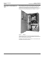
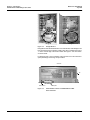
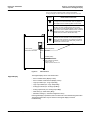
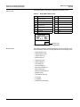
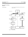
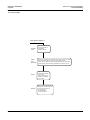
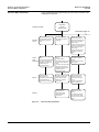
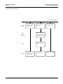
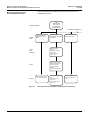
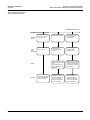
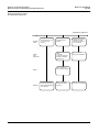
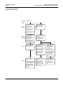
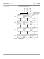
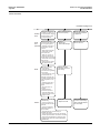
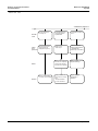
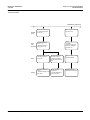
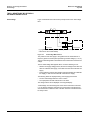
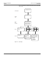
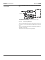
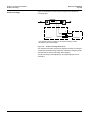
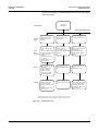
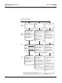
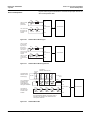
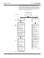
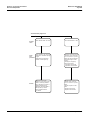
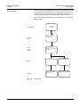
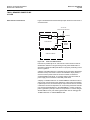
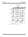
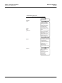
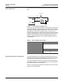
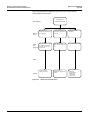
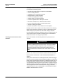
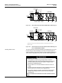
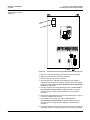
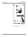
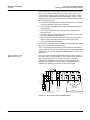
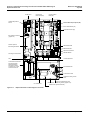
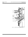
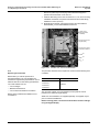
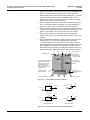
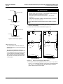
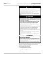
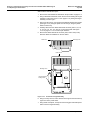
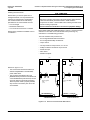
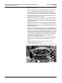
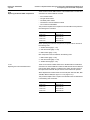
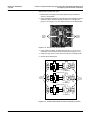
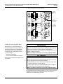
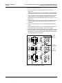
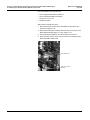
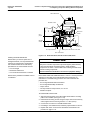
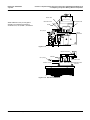
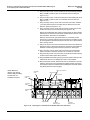
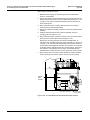
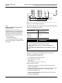
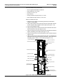
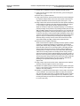
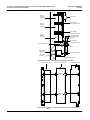
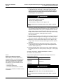
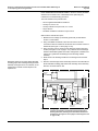
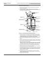
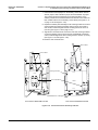
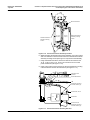
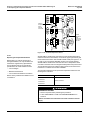
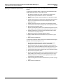
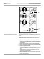
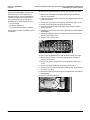
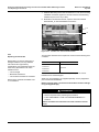
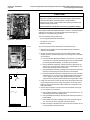
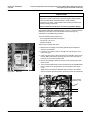
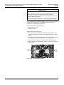
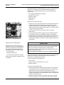
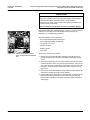
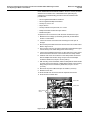
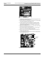
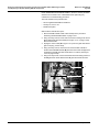
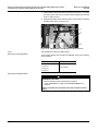
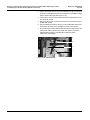
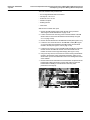
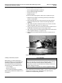
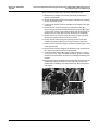
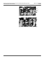
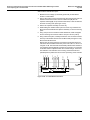
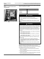
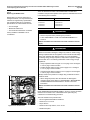
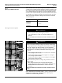
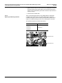
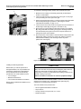
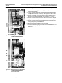
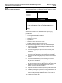
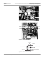
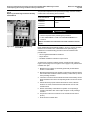
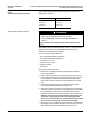
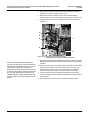
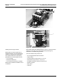
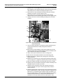
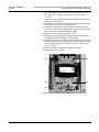
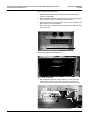
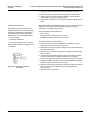
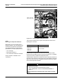
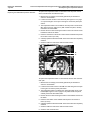
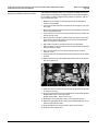
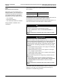
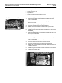
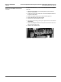
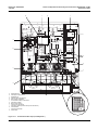
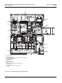
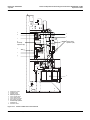
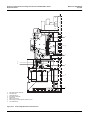
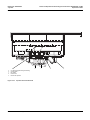
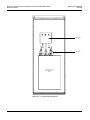
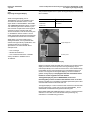
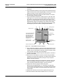
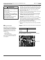
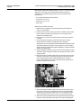
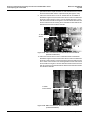
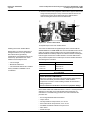
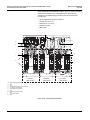
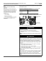
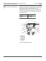
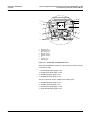
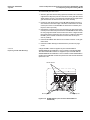
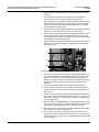
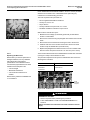
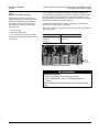
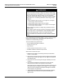
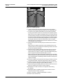
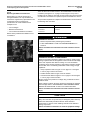
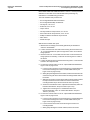
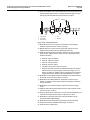
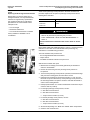
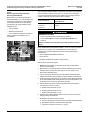
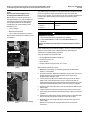
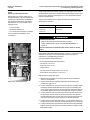
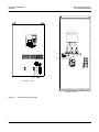
Section 4.1–Replacement Part Change Out Instructions ATV66C10N4-C19N4 Design A
4.1.9 Replacing the Dynamic Braking IGBT Kit Components
Bulletin No. VD0C06S702
July 2000
Read “WORK PRACTICE PRECAUTIONS” in section 1 and the precaution
statement on the inside cover of this bulletin before performing any
maintenance or troubleshooting procedure.
The tools needed for this procedure are:
• Set of magnetized flat blade screwdrivers
• Set of magnetized Phillips screwdrivers
• Hex key set, 2 to 14 mm
• Drive socket set, 5.5 to 14 mm
• Needle nose pliers
• Rubbing alcohol
• Clean cloth
With the drive controller door open:
1. Remove the DB snubber board as described in the procedure on
page 4.1.35.
2. Using needle nose pliers, carefully disconnect and pull back out of the
way the T2 sensor wire (see Figure 4.1.16 on page 4.1.32).
3. Using a hex key wrench, loosen and remove the screw at the back of the
T2 terminal block. Pull the T2 power cable back out of the way.
4. Using a hex key wrench, loosen and remove the motor current sensor
mounting bracket screw.
5. Using a hex key wrench, remove the remaining DB bus bar bracket screw
(see Figure 4.1.19). Remove the bus bar bracket.
6. Using a drive socket, remove the two standoffs. Pull the Q7-C jumper
back out of the way (see Figure 4.1.20 on page 4.1.45).
7. Using a hex key wrench, remove the screw from the DM4-2 terminal of
the DB diode module (see Figure 4.1.20). Pull the DM4-2 cable back out
of the way and remove the DB diode module connector (see Figure
4.1.20).
8. Using a hex key wrench, remove the two DB diode module screws. Using
a flat blade screwdriver, gently pry loose the diode module (see Figure
4.1.20). Be careful not to damage the surface of the heatsink.
9. Remove the DB diode module. Remove all traces of Thermstrate™
thermal interface compound from the heatsink with rubbing alcohol and
a clean cloth. Failure to clean the heatsink before installing the new diode
module may affect performance and longevity.
4.1.44
© 2000 Schneider Electric All Rights Reserved