1
Bulletin No. VD0C06S702
July 2000
Section 4.2–Replacement Part Change Out Instructions ATV66C10N4-C19N4 Designs B and C
4.2.15 Replacing the Discharge Resistor
To install a discharge resistor:
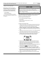
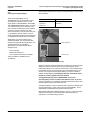
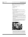
1. Install Thermstrate™ thermal interface material on the back of the new
discharge resistor. Remove the paper backing from the Thermstrate™
material, but do not remove the white contact grease coating.
NOTE: If the Thermstrate™ material is damaged (i.e., wrinkled or having
gaps in the coating greater than 1/8” round), discard it and start over with
a new one.
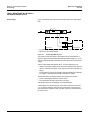
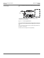
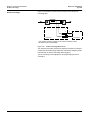
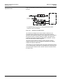
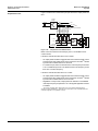
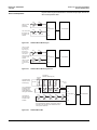
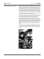
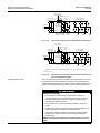
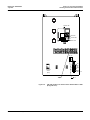
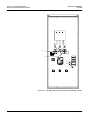
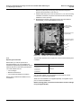
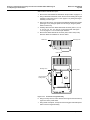
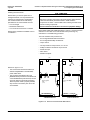
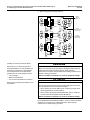
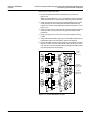
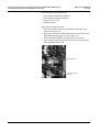
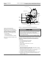
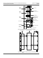
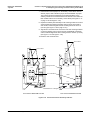
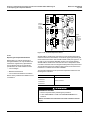
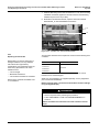
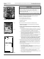
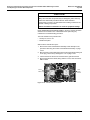
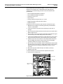
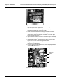
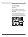
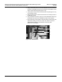
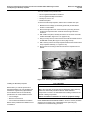
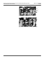
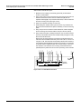
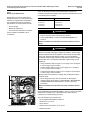
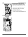
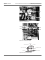
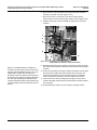
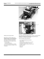
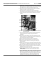
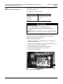
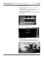
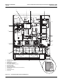
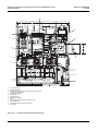
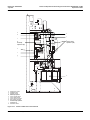
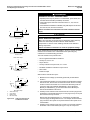
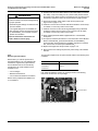
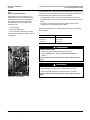
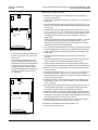
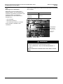
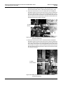
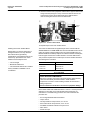
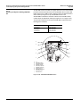
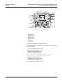
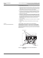
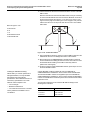
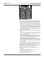
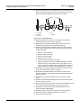
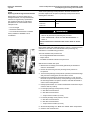
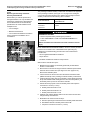
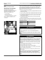
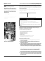
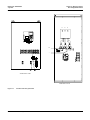
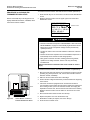
2. Place the discharge resistor on the heatsink and secure with two
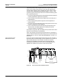
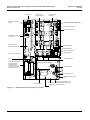
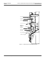
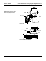
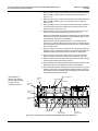
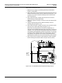
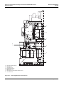
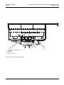
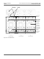
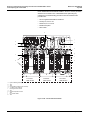
mounting screws (B in Figures 4.2.33 and 4.2.34 on page 4.2.62). Torque
the screws to 18 lb-in (2 N•m).
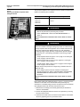
3. Replace the DC bus connections to the discharge resistor (A in
Figures 4.2.33 and 4.2.34) and secure with two screws. Torque the
screws to 34 lb-in (3.8 N•m).
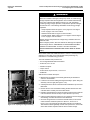
4. After installing discharge resistor 1, reinstall the lower inverter laminated
bus assembly following the procedure on page 4.2.20.
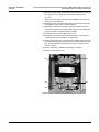
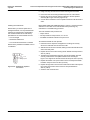
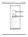
5. Close the PIB cover (see Figure 4.2.6 on page 4.2.13) and secure with
two captive thumb screws.
6. Perform “Procedure 5: Validation After Repair” in section 5.
7. Close the drive controller door.
© 2000 Schneider Electric All Rights Reserved
4.2.63