1
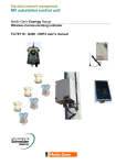
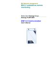
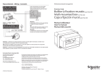
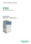
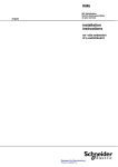
MV network management
Technical data sheet
2008
Easergy W200 - W500
Network remote monitoring
PE40000
Presentation
The W200 is a product dedicated to remote monitoring
of MV/LV substations
It provides the following functions:
b recording power and temperature measurements
b recording data from 6 digital inputs
b sending orders via 3 outputs
b detecting breaks in voltage
b communicating via GSM.
Data is accessed:
b via Intranet/Internet through the Easergy W500 server which can generate email
alarm messages
b by SMS messages on a cell-phone.
The W200 exists several versions
Basic version
6 digital inputs (DI), 3 relay outputs (DO) and GSM link.
Version with 1 measurement channel with CT
Basic version with 3 analog inputs (I) for current measurement (3 phases),
plus an analog input (θ) for transformer temperature measurement and one voltage
measurement analog input (U).
This version includes 3 opening current sensors (CT) adapted to measuring currents
with a rating of 1300/1.
Version with 1 measurement channel without CT
This version is equivalent to the previous one. It can be adapted to all types
of sensors CT supplying a secondary current (0-5A).
The W500 is an INTRANET access server
b
v
v
b
b
Cat. no
W200
W500
62402
62407
62404
62400
Integrated in the company INTRANET network:
password protection
possibility of INTERNET access
RTC communication with substations
HTTP server compatible with standard browsers.
Sales reference
Base
6 DI, 3 DO, GSM
Metering
1 LV channel
3 I, U, θ
W200SG2ZZZ
W200SG2L1A
W200SG2N1Z
W500
b
b
b
b
b
W500 WEB server (CD-Rom)
Sensors
3 CT
Not supplied
Application
Digital data
1 MV/LV transformer
PE40000
Easergy W200
Description of functions
Operating and maintenance aid
Voltage measurement
Voltage measurement is taken on one phase (W200 power supply).
This measurement enables monitoring of the quality of service and generating
of an alarm if the voltage is too low (adjustable low threshold).
Apparent power measurement
The RMS current and RMS power are measured on the LV busbars.
The aim is to give information on the change in the transformer’s apparent power.
Transformer temperature measurement
The temperature is taken using a PT100 sensor in the transformer.
Inputs - outputs
The 6 digital inputs enable specific requirements to be met relative
to MV/LV substation operation, such as:
b detection of LV fuse blowing
b adding of MV fault indicators
b opening of the MV/LV substation door
b substation in local/remote mode
b position of MV switches.
Similarly, the 3 output relays can be used to remotely control a device in the substation.
The operator has the possibility of programming an alarm in the case of a change
in status.
Recording suited to substation monitoring
Recording suited to substation monitoring
b Integrated power every 10 minutes
b Hourly average over the past week and for the week with the year’s peak value
b Maximum per day and per month over 1 year
b Maximum per year.
Logging of 200 date-stamped events
b Voltage breaks
b MV/LV transformer temperature thresholds
b Power thresholds
b Miscellaneous substation data (equipment, actions...)
b Recording changes in status of inputs/outputs.
Communication
b Integrated GSM interface or RS232 link
b Automatic event-related call (alarms)
b Cyclic call.
Configuration
b Local with laptop PC
b Remote via the INTRANET network.
Description of functions
PE55130
Easergy W500
Easergy W500 server software
Characteristics:
b PC software running under Windows 98, NT or 2000
b requires a Modem on the COM1 serial port
b manages the database of data from W200 units (up to 8,000 substations),
b custom text for each substation (600 characters)
b integrated in the corporate Intranet network or in Internet
b http server compatible with standard browsers.
Functionalities:
b file download
b reports (view and print) of event files and measurements or import
in another database
b remote parameter configuration.
For more details refer to the W500 user’s manual.
Internet/Intranet version
Alarms
DE55441
The alarms are triggered by the crossing of a threshold (temperature, power or
voltage) or even by modifying the status of one of the digital inputs.
A GSM call to the Easergy W500 server is initialized which will give e-mail alarms
to the operators concerned and/or send an SMS according to the selected settings.
W200
W500
Event log
The W200 record the last 150 events in an event log.
Each new connection enables the Easergy W500 server log to be updated.
@
“Local configuration” mode
This enables the W200 to be configured locally using a PC running under Windows
(98, NT, 2000 or XP) and a specific lead.
Menu-based W200 configuration and operation:
b communication parameter definition (telephone n°, SMS…)
b setting alarm thresholds for powers, voltages and temperatures
b viewing RMS and active currents, voltages and powers, temperatures
and digital data
b recovering W200 recorded values in file form
b development tools
b setting up automatic daily calls.
Simplified installation
Easergy W500 is distributed on CD-Rom
The computer on which Easergy W500 is installed requires:
b 1 RTC modem type V90
b 1 Ethernet link
b 1 browser (Internet Explorer®, Netscape®, ...).
Easergy W200 - W500
Characteristics
Easergy W200
Measurement inputs
Quantity
Current measurement with CT
3
Easergy sensors; busbars 70 x 6 mm
Accuracy 3%; measurement between 0 and 1500 A
Current measurement without CT
3
Current accuracy 1%
Voltage measurement
1
Supply voltage measurement (just one phase)
Accuracy of 1% between 180 and 270 V
Temperature measurement
1
Sensor: PT100 sensor (2 wires)
Accuracy 5%; measurement between -25 and +150°C
Calculated measurements
Active power
Accuracy 3%; integrated over 10 min
RMS power
True RMS up to harmonic 17
Accuracy 3%; integrated over 10 min
Power factor
Digital inputs-outputs
Accuracy 3% from 0.8 capacitive to 0.5 inductive
Quantity
Powered inputs
6
5 VDC
Dry contact outputs
3
Relay outputs (2 A at 230 VAC)
IEC 61010
Insulation (50 Hz/1 min): 2 kV
Characteristics
Electromagnetic
Climatic
EN 60-950
Impulse voltage (1.2/50 µs): 5 kV
Electrostatic discharge
IEC 1000-4-2
Level 3
Level 3
Radiated field
IEC 1000-4-3
Fast transients
IEC 1000-4-4
Level 4
Impulse waves
IEC 1000-4-5
Level 3
Radio frequency
IEC 1000-4-6
Level 3
Magnetic field 50 Hz
IEC 1000-4-8
Level 4
Voltage breaks
IEC 1000-4-11
–
Damped oscillating waves
IEC 1000-4-12
2.5 kV common mode, 1 kV differential mode
Impulse wave
IEC 1000-4-5
Between lines 1 kV, between lines and earth 2 kV
Emissions
EN 55011
Class A
IEC 68-2-3
Less than 95% at 40°C, without condensation
Temperature
Relative humidity
Mechanical
-25°C to +55°C
Salt mist
IEC 68-2-11
168 h
Storage temperature
IEC 68-2-14
-40°C to +70°C
Vibrations
IEC 68-2-6
10 to 500 Hz; 1 g or 0.075 mn peak to peak
Protection
IEC 60529
IP21
ART.832553 © Schneider Electric Industries SAS - All rights reserved
Dielectric
Power supply
Supply voltage
230 VA ±15% 50 Hz/60 Hz
Battery
2 h battery life
Integrated GSM modem
Dual-band 900/1800 MHz
Antenna supplied with 4 m cable
Measurement extension
3 current measurement inputs and a PT100
Server installed on PC
Windows 98, NT, 2000, XP
Options
Easergy W500
Server
Communication to Intranet
Ethernet TCP/IP port
Communication to W200
Standard RTC modem (COM1) not supplied
Capacity
8,000 substations
Schneider Electric Industries SAS
89, boulevard Franklin Roosevelt
F-92506 Rueil-Malmaison Cedex
Tel: +33 (0)1 41 29 85 00
www.schneider-electric.com
www.easergy.com
ENMED307023EN
As standards, specifications and designs change from time to time, please ask for confirmation
of the information given in this publication.
This document has been printed
on ecological paper
Publishing: Schneider Electric Industries SAS
Design: Schneider Electric Industries SAS
Printing: Imprimerie du Pont de Claix/JPF - Made in France
10-2007