1
User Guide
Ethernet Client Bridge
3CWE820A
Wireless Network Solution
http://www.3com.com/
http://www.3com.com/productreg
Published March 2001
User Guide version 1.0.0
3Com Corporation
■
5400 Bayfront Plaza
■
Santa Clara, California
■
95052-8145
■
U.S.A.
Copyright © 2001 3Com Corporation. All rights reserved. No part of this documentation may be reproduced in any form or by any means or
used to make any derivative work (such as translation, transformation, or adaptation) without written permission from 3Com Corporation.
3Com Corporation reserves the right to revise this documentation and to make changes in content from time to time without obligation on the
part of 3Com Corporation to provide notification of such revision or change.
3Com Corporation provides this documentation without warranty, term, or condition of any kind, either implied or expressed, including, but
not limited to, the implied warranties, terms or conditions of merchantability, satisfactory quality, and fitness for a particular purpose. 3Com
may make improvements or changes in the product(s) and/or the program(s) described in this documentation at any time.
If there is any software on removable media described in this documentation, it is furnished under a license agreement included with the
product as a separate document, in the hard copy documentation, or on the removable media in a directory file named LICENSE.TXT or
!LICENSE.TXT. If you are unable to locate a copy, please contact 3Com and a copy will be provided to you.
UNITED STATES GOVERNMENT LEGEND
If you are a United States government agency, then this documentation and the software described herein are provided to you subject to the
following:
All technical data and computer software are commercial in nature and developed solely at private expense. Software is delivered as
“Commercial Computer Software” as defined in DFARS 252.227-7014 (June 1995) or as a “commercial item” as defined in FAR 2.101(a) and
as such is provided with only such rights as are provided in 3Com’s standard commercial license for the Software. Technical data is provided
with limited rights only as provided in DFAR 252.227-7015 (Nov 1995) or FAR 52.227-14 (June 1987), whichever is applicable. You agree not to
remove or deface any portion of any legend provided on any licensed program or documentation contained in, or delivered to you in
conjunction with, this User Guide.
Portions of this documentation are reproduced in whole or in part with permission from (as appropriate).
Unless otherwise indicated, 3Com registered trademarks are registered in the United States and may or may not be registered in other
countries.
3Com is a registered trademarks and the 3Com logo is a trademark of 3Com Corporation.
Microsoft, Windows, and Windows NT are registered trademarks of Microsoft Corporation. Wi-Fi is a trademark of the Wireless Ethernet
Compatibility Alliance.
All other company and product names may be trademarks of the respective companies with which they are associated.
Contents
1
Wireless Network Topologies
Infrastructure Topology
Ad Hoc Topology
2
Getting Started
ECB Kit Contents
System Requirements
Configuration Flowchart
3
Installing the Hardware and Software
Physical Dimensions
LED Indicators
Installing the Hardware
ECB Configuration Utility Software
Windows
Linux
4
Configuration Utility Features
Client Bridge List Screen
Configuration Screen
Saving a Configuration
Loading a Configuration
Changing the Password
Updating ECB Firmware
Resetting to Factory Defaults
Changing Your Radio Type
Log Viewer
GUI Message Log
Event Log
Association Log
Forward Table
5
Configuring Radio Settings
1
1
2
3
3
3
3
5
5
5
6
9
9
9
11
11
11
12
13
14
15
16
16
17
17
17
17
18
Basic Radio Configuration
Advanced Radio Configuration
Encryption
19
19
20
20
6
Using the ECB as a Wireless Ethernet Bridge
23
7
Configuring Network Settings
25
25
Network Configuration Settings
Contents
8
9
10
Configuring General Serial Settings
Configuring Universal Asynchronous Receiver/Transmitter (UART) Settings
Flow Control
Hardware Flow Control
Software Flow Control
Configuring Flow Control
Serial Packets
27
27
28
28
28
29
29
Configuring Wireless Printing to a Serial Printer
31
Serial Line Replacement
33
33
33
34
36
36
36
RMP Pipe
Configuring RMP Pipe
RMP Pipe Parameters
I/O Control
TCP Pipe
Configuring TCP Pipe
11
Configuring the ECB as a Network Serial Port
TCP Listen Port
TCP Connect Port
12
Configuring the ECB as a Serial Telnet Client
Wait for Keystroke Connection
Command Prompt Connection
13
Troubleshooting
Firmware Updates
Problem Diagnosis
Event Log Error
A
Terminal Configurator
Establishing a Direct Serial Connection
Establishing a Telnet Connection
Using the Terminal Configurator
Main Menu Overview
Using The Editor
Configuration File Format
File Contents
System
RS-232 Port (uart0)
39
40
41
43
44
45
47
47
47
48
49
49
50
51
51
52
53
53
53
54
Contents
B
Network Bindings
Bridged Ethernet (lan0)
Terminal Configurator Error Codes
59
60
62
Serial Stream to Network Packet Conversion
63
63
64
64
65
Line Length
Timeout
Delimiters
Configuration
C
Customer Support
Online Technical Services
World Wide Web Site
3Com Knowledgebase Web Services
3Com FTP Site
Support from Your Network Supplier
Support from 3Com
Returning Products for Repair
67
67
67
67
67
68
68
70
Index
71
Warranty and Software License Agreement
77
77
79
79
80
3Com Corporation Limited Warranty
FCC Class B Statement
FCC Declaration of Conformity
3Com End User Software License Agreement
1
Wireless Network Topologies
The 3Com Ethernet Client Bridge can be easily integrated into your existing wireless network, or multiple ECB
units or other clients can be used to create a new wireless network. A wireless network, or wireless LAN, acts
as an extension or alternative to a wired network within a building or campus. Data is transmitted and
received using radio waves. In a wireless LAN environment, no cabling is needed between nodes for data
communication. There are two topologies in which a 3Com ECB may be used: infrastructure, which requires
an access point, and 802.11 Ad Hoc, which does not. A detailed description of each is provided below.
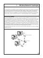
Infrastructure Topology
Infrastructure topology is the most commonly used of the two types available for use of your 3Com ECB.
Infrastructure mode requires the use of a device called an access point (AP). The main function of the AP is to
form a bridge between the wired LAN and wireless clients. The AP is capable of filtering high rate wired traffic
and transmitting only those packets that are destined to radio clients. You might think of the AP as a hub
between the wired network and the wireless LAN. In this mode, the AP is a dedicated device that is wired into
the LAN backbone. The AP remains as a stationary part of the wireless LAN, unlike individual ECB units that can
be physically moved throughout the wireless LAN. In this mode, the ECB stations synchronize communication
with the AP. Individual ECB units do not communicate directly with each other. All communication between ECB
units or between an ECB and a wired network client must go through the AP (Figure 1).
Infrastructure mode is often used in systems that have heavy network traffic and want to utilize the filtering
capabilities of the AP.
Figure 1
10BASE-T
Ethernet Client Bridge (ECB)
Access Point (AP)
R
POWE
ESS
NET
ETHER
WIREL
1
1
Wireless Network Topologies
The re-association capabilities of the IEEE 802.11 standard enable clients to move throughout the wireless
LAN area and roam between access points. Re-association can occur as long as the ECB has the same ESSID
(network name) as the AP to which it is trying to make a connection.
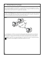
Ad Hoc Topology
The 802.11 Ad Hoc topology allows multiple ECB units to communicate directly with each other, without the
need for an access point (AP) or other wireless infrastructure. Figure 2 shows a network in which four ECB
units are used to provide wireless connectivity between Ethernet devices.
Figure 2
10BASE-T
ECB
In this configuration, the ECB units make all three devices appear to be connected by the same Ethernet
cable. Using ECB units in this manner provides a cost effective way to wirelessly link a small number of
Ethernet devices. In addition, ECB units eliminate the need to install expansion cards or driver software.
NOTE: A single ECB is only capable of bridging for a single Ethernet device. A single ECB cannot be
connected to a hub and bridge for multiple Ethernet devices on the hub.
2
2
Getting Started
This chapter describes the contents of the 3Com Ethernet Client Bridge package, the system requirements, a
pre-configuration information sheet, and a configuration flowchart.
ECB Kit Contents
In your Ethernet Client Bridge package, you will find the following components:
■ Ethernet Client Bridge
■ RJ-45 Ethernet cable
■ 5.2V Universal AC-to-DC power adapter
■ AC Power cord
■ DC Power cable
■ Printed quick start guide
■ Installation CD containing a user guide and configuration software
■ Mounting hardware
If any of these items are missing or damaged, please contact the place of purchase or 3Com Customer
Support (http://www.support.3com.com).
System Requirements
■
■
■
■
One or more 3Com ECB units.
One Wi-Fi-compliant wireless LAN PC Card for each ECB. For a list of supported PC Cards, visit the
3Com service and support Web site at http://www.support.3com.com.
If the ECB will be used with an access point (AP), you will need an AP that either is compatible with the
PC Card(s) being used, or is Wi-Fi compliant.
Computer with Windows 95, 98, Windows 2000, Windows NT, or Linux with X11 Windows Manager
and GTK installed.
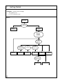
Configuration Flowchart
Figure 3 shows the configuration steps for your ECB. Start at the top of the flowchart and move downward
progressing toward a desired use of the ECB. As you move down the flowchart, the bulleted lists of
configuration parameters you pass through are the parameters you need to set. There may be additional
parameters that you can use to further control the behavior of the ECB for each application; however, only
parameters that need to be modified for proper operation are listed in this chart.
Example 1 – For the ECB to act as an LPD Print Server, you will need to set the following parameters:
■
■
■
ESSID (network name)
Baud Rate
Data Bits
■
■
■
Stop Bits
Parity Bits
Flow Control
■
■
■
IP Address
Netmask
Gateway
3
2
Getting Started
Example 2 - Wireless Ethernet Bridge
You need only set:
■
ESSID (network name)
Figure 3
3Com ECB
·
ESSID
(network name)
Serial port
application
Wireless
Ethernet Bridge
rate
··Baud
Data bits
bits
·Stop
bits
··Parity
Flow control
Address
··IPNetmask
·Gateway
RMP pipe
IP
··Remote
Remote port
·Local port
·Local port
IP
··Remote
Remote port
TCP/IP pipe
TCP/IP listen
port
TCP/IP connect
port
Telnet
LPD print
server
IP
··Remote
Remote port
Command
prompt method
4
Wait for
keystroke method
3
Installing the Hardware and Software
This chapter describes the physical dimensions of the ECB unit, the LED indicators, and hardware and
software installation procedures.
Physical Dimensions
If you want to mount the ECB on a vertical surface, refer to the outside dimensions and mounting hole
dimensions of the mounting plate shown in Figure 4. Primary dimensions are given in inches and secondary
dimensions are in [mm].
Figure 4
Use #6 or M4 flathead fasteners
for mounting bracket
3.89"
(99mm)
.50"
(13mm)
1.95"
(49mm)
.77"
(20mm)
3.38"
(86mm)
6.20"
(157mm)
1.10"
(28.0mm)
LED Indicators
As shown in Figure 5, there are five LED indicators:
■ Power – Lights green when power is applied.
■ Alert – Lights amber when status information is available.
■ Wireless – Lights green when the PC Card is associated to another client and lights amber during radio
communication.
■ Ethernet – Lights green to show that a valid Ethernet link is present on the 10BASE-T port. Lights amber
during Ethernet activity.
■ Serial – Lights green when receiving data on the serial port and lights amber when transmitting data out
the serial port.
5
3
Installing the Hardware and Software
Figure 5
Ethernet Client
Bridge
Power
Alert
Wireless
Ethernet
Serial
Installing the Hardware
This section will guide you through the hardware installation of the 3Com ECB including the installation of
the wireless LAN PC Card. Please note that the user manual that accompanied your wireless LAN PC Card
should be used in combination with this manual for many of the advanced configurations.
NOTE: The 3Com ECB does not include a wireless LAN PC Card. These cards are sold separately. Please
see the 3Com Web site at www.support.3com.com for the most current list of 3Com PC Cards
supported by your ECB.
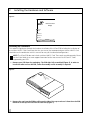
1 Remove your ECB from the packaging. The ECB ships fully assembled (Figure 6). In order to
install the radio and use the ECB, some disassembly and re-assembly is required.
Figure 6
Eth
Se
rial
Ale
Wir
rt
ern
ele
et
ss
Po
we
r
Eth
e
Bri rnet C
dge lie
nt
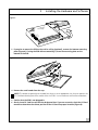
2 Remove the cap from the ECB by pulling on the side of the cap to release it from the main ECB.
Removal of the cap will reveal the PC Card slot (Figure 7).
6
3
Installing the Hardware and Software
Figure 7
t
et Clien
Ether n Bridge
Power
Alert
s
Wireles et
Ethern
Serial
3 If you plan to mount the ECB on the wall or ceiling (optional), remove the bottom mounting
plate (Figure 8). If using the ECB without mounting it, leave the mounting plate on the
bottom of the ECB.
Figure 8
4 Remove the small combs from the cap.
NOTE: The combs are generally not needed, but when cut to an appropriate size, they can prevent the
PC Card from vibrating out of the socket when the ECB is in an environment with extreme vibrations
5 Confirm that the ECB is not plugged in.
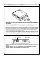
6 Gently insert PC Card face up into the designated slot. If you are uncertain, check the PC Card
manual to determine the correct position of the PC Card for proper insertion (Figure 9).
7
3
Installing the Hardware and Software
Figure 9
r
le
A
er
w
Po
Eth
e
Bri rnet C
dge lie
nt
t
ire
W
ss
le
th
E
er
ne
l
ia
t
er
S
7 Replace the cap on the ECB that you removed in step 2 by snapping the cap straight down on
the ECB body.
8 If you are mounting the ECB, install the mounting plate where desired using the mounting
hardware provided (see Figure 4 for physical dimensions of the mounting plate).
9 After securing the mounting plate to the desired location, attach the ECB onto the mounting plate.
10 Connect the six-pin DC power cable to the power adapter. Connect the AC power cord to the
other side of the power adapter. Connect the round power plug to the ECB port labeled
5 VDC. Insert the AC power cord into the AC socket.
11 Connect a standard straight-through 10BASE-T Ethernet cable between the RJ-45 port on the
ECB and the network port on the computer where you will install the ECB Configuration
Utility software (see Figure 10 for ECB connectors).
Figure 10
Power
jack
10BASE-T
Ethernet port
Configuration
Serial port button
10
5 VDC
RJ-45
Serial
Config.
12 Verify that the Ethernet LED is illuminated (Figure 5), indicating a valid Ethernet connection to
your PC.
13 Your ECB hardware is now ready for configuration using the ECB Configuration Utility
software. Proceed to “ECB Configuration Utility Software” below.
8
3
Installing the Hardware and Software
ECB Configuration Utility Software
The ECB Configuration Utility software can be installed on a PC or workstation running either Windows 95,
98, Windows 2000, Windows NT, or Linux with X11 Windows Manager and GTK installed. This utility allows
you to graphically and remotely:
■ Display a list of ECB units running on the local network
■ Display and edit the current configuration of any ECB
■ Save and load configurations
■ Update the ECB firmware
NOTE: The ECB Configuration Utility software communicates with the ECB using a non-routable
protocol. This means that your ECB units must be accessible on the local Ethernet network in order to
communicate with the ECB Configuration Utility.
In the event the Configuration Utility is not available, the Terminal Configurator is an alternative method that
can be used to configure the ECB. See Appendix A for more information.
Windows
1 Insert the Installation CD into the appropriate drive of your computer.
If the installation program does not begin automatically, click My Computer on your desktop.
Click the icon for the drive in which the Installation CD is located, and then double-click setup.exe.
2 The Welcome screen will appear first. Choose Next to continue the installation or Cancel
to terminate.
3 The Software License screen appears. Choosing Yes indicates that you agree to the terms presented
and will allow the continuation of installation. Choosing No will terminate the installation.
4 The Choose Destination screen appears next. This screen contains the default path and
location for the ECB_Config.exe file. The default path is:
C:\Program Files\3Com\ECB_Config\
5 If you wish to use the default path, then continue to the next screen by clicking Next. You may
choose another path and location for the ECB Configuration Utility that is more appropriate
for your system. If you choose to do this, simply type the path into the field and continue by
clicking Next.
6 The Select Program Folder screen will now appear. This screen allows you to change the name
of the program folder that will be created. The default name is ECB_Config.
7 Click Finish to complete the installation of the ECB Configuration Utility software.
The ECB Configuration Utility software is now installed and you are ready to configure your ECB.
Linux
1 Ensure that X11 Windows Manager and GTK are installed on your system.
2 Copy the files located in the Linux directory on the Installation CD to a directory on your
Linux machine.
3 Run the ECB_Config utility by typing ./ECB_Config from the directory where you installed the files.
9
4
Configuration Utility Features
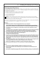
Client Bridge List Screen
The initial screen of the ECB Configuration Utility will display a list of the ECB units currently detected on the
Ethernet. All ECB units can be accessed from this main screen. The buttons on this screen allow you to scan,
exit, and configure a unit, and display the help page. The scan function allows you to perform a new search
for active ECB units. After a scan is executed, any previously displayed ECB units that are no longer found will
be removed from the list, and new ECB units will be displayed.
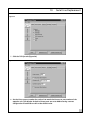
At the start-up of the ECB Configuration Utility, the program displays a list of available ECB units (Figure 11).
Begin by highlighting the ECB that you wish to configure. Either click Configure or double-click the desired
ECB listing.
Figure 11
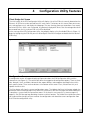
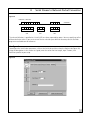
Configuration Screen
A configuration screen will appear displaying information about the ECB Configuration Utility and the
selected unit (see Figure 12). The vertical tabs define the categories of configuration options. There are three
tabs: Network, Serial, and Radio. Horizontal tabs expose different sub-categories described further within
each specific section. There are three buttons at the bottom of the screen: Close, Reload From Unit, and
Update And Reset Unit.
The Close button will close the current configuration screen. The Update And Reset Unit button uploads the
parameters from the configuration utility to the ECB, and resets it so that the changes take effect. Before this
is complete, a syntax check of all parameters occurs. If the check is not successful, an error message will
appear in the GUI Message Log describing the errors and their location. The Reload From Unit button allows
you to discard the changes you have made to the configuration and reload the current configuration from
the ECB to the configuration utility.
11
4
Configuration Utility Features
Figure 12
The Configuration screen has a File menu that will allow you to:
■ Save or load a configuration
■ Reset the ECB to factory defaults
■ Set a new password or clear it
■ Access a view of the log files
■ Update the ECB firmware.
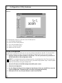
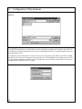
Saving a Configuration
Using the ECB Configuration Utility, you can save the settings of the ECB to a local file. This feature allows
you to restore settings to a known state or easily configure multiple ECB units with the same settings.
1 Begin by clicking the Update And Reset Unit button. This will synchronize the parameters in
the ECB with those in the configuration utility.
NOTE: The saved parameter values are those currently in the configuration utility. To ensure you save
your changes to both a local file and the ECB itself, you should always perform Step 1 and click Update
And Reset Unit before saving your configuration.
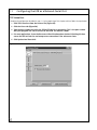
2 Go to the File menu of the ECB Configuration Utility main screen.
3 Select Save Configuration.
4 Use the dialog box (Figure 13) to navigate to the directory where you would like to save the
current configuration. The default path is the ECB_Config program directory.
5 Click Open. (In this case, the Open button is used to save the file).
12
4
Configuration Utility Features
Figure 13
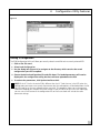
Loading a Configuration
The ECB Configuration Utility will allow you to easily reload a saved file to the currently selected ECB.
1 Click on the File menu.
2 Select Load Configuration.
3 Use the dialog box (Figure 14) to navigate to the directory which contains the saved
configuration you wish to upload.
4 Choose the desired configuration file and click Open. The loaded parameters will now be
displayed in the configuration utility, but have not been uploaded to the ECB.
5 To activate the parameters, click Update And Reset Unit.
NOTE: If the PC Card in the active ECB is different than the PC Card that was in the ECB when the
configuration parameters were saved, all parameters but the radio options will be loaded from the file.
You will need to set the new radio parameters manually. This procedure allows you to change your
radio while keeping your network and serial settings. If you will continue to use this new radio type,
you can save a new version of the configuration file so that future loads will include the radio
parameter settings.
13
4
Configuration Utility Features
Figure 14
Changing the Password
Setting a password prevents unauthorized users from accessing or changing the settings on your ECB. You
will need to enter this password each time you wish to reconfigure the ECB. It is recommended that you set a
password for each ECB.
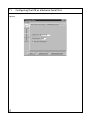
The selection Set New Password in the File menu lets you set or change a password on your ECB. A dialog
box (Figure 15) will ask you to type the new password twice. Clicking Update Password Now will cause the
new password to become immediately active. Entering blank text will remove the password. The utility will
not prompt for a password when it is empty.
Figure 15
14
4
Configuration Utility Features
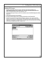
Updating ECB Firmware
1 Begin by downloading the latest version of firmware from the 3Com Web site at
www.support.3com.com to the computer that is currently running the ECB Configuration
Utility. The firmware file will have the extension ".rmu".
2 After downloading the firmware, click File in the Main screen of the ECB Configuration Utility
(Figure 12).
3 Select Upload Firmware from the options.
4 Use the file selector (Figure 16) to navigate to the location of the firmware file.
5 Double-click on the file. The Log Viewer will display a progress status. At the end of the
process, your ECB will reset. The Log Viewer will announce that your ECB has been properly
updated. The Alert light on the ECB will flash, and after about 15 to 20 seconds the new image
will be fully installed and your ECB is ready for use.
Figure 16
15
4
Configuration Utility Features
Resetting to Factory Defaults
1 Begin by clicking File in the main screen of the ECB Configuration Utility (Figure 12).
2 Select Reset To Factory Defaults. All of the parameters will immediately be restored to the
factory default values.
Depending on your current radio network setting, resetting to factory default might leave your ECB in a nonreachable state. Resetting to defaults resets all parameters, including the ESSID (network name). If the ECB
that was reset to the factory defaults is not on the same wired LAN section as your PC, it is possible that it will
lose association to the access point, and the configuration utility will no longer be able to communicate with
the ECB. If this happens, you will need to connect the ECB to your PC via an Ethernet cable. You will then be
able to use the configuration utility to set the ESSID (network name) to that of your access point and the ECB
will associate as desired.
If you are unable to access the ECB through the GUI, the following method can be used:
1 Disconnect power to the ECB.
2 Insert one end of an extended paper clip into the small hole labeled Config. (located near the
serial port on the ECB) to push the configuration button.
3 While keeping the configuration button pushed in, reconnect power to the ECB.
4 Keep the configuration button pushed in for at least five seconds after power is applied. The
ECB will be reset to factory defaults after the five-second period.
Changing Your Radio Type
The ECB Configuration Utility utility is designed to detect the type of PC Card you are currently using and to
reset the specific radio parameters accordingly. Consequently, if you ever want to change your PC Card and
retain the network and serial parameters of your previous PC Card, follow this procedure:
1 With your current PC Card, follow the instructions for saving a configuration as described in
“Saving a Configuration”.
2 Remove power from the ECB, switch the PC Cards, and return power to the ECB.
3 Reset to factory defaults by following the instructions above.
4 Load the configuration you have just saved by following the loading instructions in “Loading
a Configuration”. All non-radio parameters will be retrieved.
5 Set the specific parameters of your new PC Card by following the instructions described in
Chapter 5, Configuration of Radio Settings.
16
4
Configuration Utility Features
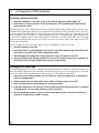
Log Viewer
You can invoke the Log Viewer screen from the File menu of the main screen by selecting Show Log Window.
The Log Viewer has two main purposes:
■ To display the different logs and tables stored on the ECB.
■ To display status and error messages from the configuration utility.
In the upper left corner of the Log Viewer screen (Figure 17), there is a File menu from which you can switch
views between the different ECB logs and the configuration utility messages.
Figure 17
GUI Message Log
The GUI Message Log displays status messages from the configuration utility.
Event Log
The event log displays messages generated by the ECB. Event log messages include basic information about
the ECB hardware and any status messages generated by the ECB. To display the event log of your ECB,
select File in the Log screen and select Read Event Log (Figure 17). To clear the entries from the event log,
select Clear Event Log from the File menu.
Association Log
The Association Log records association and disassociation events. Each association event is recorded with a
timestamp and, if available, the access point MAC address and ESSID (network name). Each disassociation
event contains only a timestamp. The timestamp indicates the number of 10 millisecond periods since the
unit was turned on or reset. For example, a timestamp of 6000 corresponds to a time of 60 seconds, and a
timestamp of 20 corresponds to a time of 0.2 seconds.
17
4
Configuration Utility Features
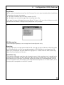
Forward Table
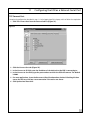
The Forward Table (Figure 18) displays the MAC addresses that have been seen by the ECB. The table lists the
interface, wire, or PC Card, where each MAC address was observed. The time for each entry indicates the
number of seconds until that entry is removed from the forwarding table.
Figure 18
18
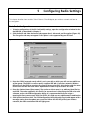
5
Configuring Radio Settings
This chapter describes how to add a 3Com Ethernet Client Bridge to your wireless network and how to
use encryption.
Basic Radio Configuration
1 To begin configuration of the PC Card (radio) settings, open the configuration window for the
desired ECB, as described in Chapter 4.
2 Click the Radio tab. New horizontal tabs appear: Basic, Advanced, and Encryption (Figure 19).
The Encryption tab may not appear if this option is not supported by your PC Card.
Figure 19
3 Enter the ESSID (network name) which is set in your AP or which you will use to establish an
ad hoc group. The ESSID is used to specify a unique IEEE 802.11 wireless network. Wireless
ECB units use the ESSID to associate to a specific access point (AP). Only devices with the same
ESSID will associate with each other. Alphanumeric values may be used in this field.
4 Enter the Station Name (client name). The station or client name is an arbitrary identifier for
each ECB. The value supplied in this field is for convenience in identifying the ECB units with
software such as the ECB Configuration Utility. It is recommended that you assign a
meaningful client name to each ECB. Like ESSID, this field uses any alphanumeric combination.
5 Click Update And Reset Unit. The ECB Configuration Utility Message Log should appear with a
message stating that the update was successful. When the ECB has joined your wireless
network, the radio association LED will light green.
19
5
Configuring Radio Settings
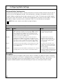
Advanced Radio Configuration
The Advanced Configuration screen is specific to the feature set of your wireless LAN card. Consult your PC
Card user manual for appropriate settings. After configuration is complete, click Update And Reset Unit.
The MAC Address setting found on this tab is common to all PC Cards. This feature sets the MAC address
used by the wireless LAN interface. The ECB can only bridge packets to or from this MAC address. There are
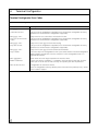
four options: Capture, Dynamic, Built-in, and Manual. Table 1 lists the definitions of each option.
NOTE: Most users should use the default setting of Capture.
Table 1 Advanced Radio Configuration Settings
Setting
Effect
Usage
Capture
Every time the ECB is powered on, the ECB will capture its MAC
address from the first packet it receives on the 10BASE-T Ethernet
port. The ECB detects and uses the same MAC address as the
device plugged into the 10BASE-T port. The ECB will use the
previously captured MAC address upon power-on until the first
packet is received on the 10BASE-T port.
Use Capture when the ECB is attached
to the same device all the time
(example: an Ethernet printer).
Dynamic
The ECB will change its MAC address each time the device
plugged into the 10BASE-T port changes. The ECB detects the
MAC address of the device plugged into the 10BASE-T port and
uses that as its own. The ECB will use the built-in MAC address
upon power-on until a packet is received on the 10BASE-T port.
Use Dynamic when you want to
change the device that the ECB
bridges for without requiring a power
cycle of the ECB (example: public
access gateway).
Built-in
The ECB will use the MAC address of the PCMCIA wireless LAN
PC Card. This will prevent the ECB from bridging for any device
on the 10BASE-T port.
Use Built-in when the ECB is used
exclusively for serial port applications
(example: network serial port without
Ethernet bridging).
Manual
The ECB will use the MAC address specified by the user. The ECB
will bridge traffic for a device with the specified MAC address.
The Manual setting should rarely be
used. This setting is needed if the ECB
is bridging to an Ethernet device that
never generates any traffic.
Encryption
The Encryption tab may not appear if your wireless LAN PC Card does not support this option. Encryption is
necessary to associate to an AP which is configured to deny unencrypted connections. Consult your PC Card
manual for a description of how to set up encryption on your PC Card. In many cases, you will want
encryption enabled to provide security for data being sent across the wireless part of your network.
20
5
Configuring Radio Settings
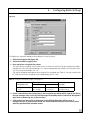
Figure 20
The following is a general procedure for enabling this security feature.
1 Click the Encryption tab (Figure 20).
2 Check the Enable Encryption box.
3 Enter up to four encryption key values.
The values for the encryption keys may be written as either text (ASCII) strings or hexadecimal numbers.
Hexadecimal values must be preceded by "0x" and are composed of the numbers 0 to 9 and the letters
A-F. Text strings cannot begin with "0x".
The level of encryption corresponds to the length of the encryption key (Table 2). See your wireless LAN
PC Card manual for the encryption levels supported by your PC Card.
Table 2 Encryption Level and Key Length Correspondence
Key Length
Encryption Level
Hex
ASCII
Example
40 bit or 64 bit
0x + 10 digits
5 characters
0xFEDCBA9876
128 bit
0x + 26 digits
13 characters
ALazyBrownDog
4 Select a transmit key. The transmit key is the encryption key which will be used by the ECB to
encrypt messages sent via the PC Card. Messages received by the PC Card will be decrypted if
they were created using any of the four keys.
5 Click Update And Reset Unit at the bottom of the ECB Configuration Utility screen. If
configured to run in infrastructure mode, the ECB should now associate to the access point
with the specified ESSID (network name).
21
6
Using the ECB as a Wireless Ethernet Bridge
The 3Com ECB can be used as a wireless Ethernet bridge for connecting a wired unit such as a computer or
Ethernet printer to your wireless network. The ECB can act as a wireless Ethernet bridge in addition to
performing any one of the serial port applications discussed in following chapters.
1 Complete the Basic Radio Configuration instructions described in Chapter 5, Configuration of
Radio Settings.
2 Click Update And Reset Unit.
3 If needed, move the ECB to the desired location. Provide power to the ECB and connect it to
the Ethernet device for which it will bridge.
Your 3Com ECB is now configured to act as a wireless Ethernet bridge to your Ethernet network component.
23
7
Configuring Network Settings
Network Configuration Settings
This chapter describes the network settings necessary to communicate with the ECB. Communication directly
with the ECB will allow the following:
■
■
■
Using the serial port applications described in the following chapters.
Performing a network "ping" of the ECB.
Remotely configuring the ECB via the Telnet protocol.
NOTE: "Bridging," as discussed in Chapter 6, is communication between the wireless interface and the
Ethernet interface. Bridging does not communicate with the ECB and does not require setting the basic
network parameters.
After completing the configuration of PC Card (radio) settings in Chapter 5, proceed with the following steps
to configure the network settings.
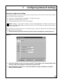
1 Click the Network Tab. Under the Basic tab, three fields are displayed as shown (Figure 21):
Figure 21
2 Enter the IP Address you wish to assign to the ECB. The IP address is the network address that
will be used by other computers to communicate with the ECB.
3 Enter the Netmask value. This is a value that defines the range of IP addresses available
within your local network.
25
7
Configuring Network Settings
4 If your network uses a gateway (router or firewall), enter the IP address of the gateway. You
will need to enter the IP address of your gateway if you plan to use the ECB to access
computers or other ECB units beyond your Internet router or firewall. A gateway entry is only
needed for serial applications that actively connect to an IP address outside your local area
network. You may enter none in this field if no gateway is present or a gateway is not
needed.
26
8
Configuring General Serial Settings
This chapter describes the general serial settings that are required for all serial port applications described in
the following chapters. For proper operation, it is imperative that these settings of the 3Com ECB always
match the settings of the device to which it is connected via the RS-232 port. There are two groups of
parameters that need to be configured to accomplish this task: UART Settings and Flow Control Settings.
Configuring Universal Asynchronous Receiver/Transmitter (UART) Settings
A Universal Asynchronous Receiver/Transmitter (UART) is the fundamental hardware for serial
communication, controlling the speed and method of data transfer of the serial port. To configure the UART,
follow the steps below.
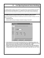
1 Click the Serial tab.
2 Click the UART tab. Figure 22 displays the default settings for the UART.
Figure 22
3 Select the baud rate of your device from the pull-down menu. The baud rate indicates the
data transfer rate of the serial port. The baud rate ranges from 300 to 115200 bits per second
(bps). Standard rates are 300, 1200, 2400, 9600, 19200, 38400, 57600, 115200.
4 Determine the data bits setting of the device you are connecting to the ECB, then select the
Data Bits setting for the ECB that matches the data bits setting of that device. The Data Bits
setting determines the number of bits used to transmit data. The possible values are 7 and 8.
27
8
Configuring General Serial Settings
5 Determine the stop bits setting of the device you are connecting to the ECB, then select the
Stop Bits setting on the ECB that matches the stop bits setting of that device. The Stop Bits
setting determines the number of bits used to represent an end of a character. The value can
be 1 or 2.
6 Determine the parity bit setting of the device you are connecting to the ECB, then select the
Parity Bit setting on the ECB that matches the parity bit setting of that device. The Parity Bit
setting is used to check for correct data transmission. Options are: none, even, and odd.
Flow Control
Flow control is the process of adjusting the flow of data from one device to another to ensure that the
receiving device can handle all of the incoming data. Flow control becomes an important factor when one of
the devices is capable of transmitting data at a rate faster than the other can receive it. There are two basic
types of flow control, hardware and software.
Hardware Flow Control
Hardware flow control uses dedicated signal lines to dictate transmission of data and has two options that
allow you to select which pair of lines to use for this type of flow control:
■ RTS/CTS = Request To Send/Clear To Send
■ DTR/DSR = Data Terminal Ready/Data Set Ready
NOTE: The Windows Hardware flow control setting uses the RTS/CTS flow control lines.
Software Flow Control
Software flow control uses two special characters, called "Xon" and "Xoff", which are embedded in the data
to turn on or off the transmission of data from the source to receiver.
In the incoming direction, flow control prevents the ECB from sending data when the computer is not ready
to accept it. With incoming flow control on, the ECB will interpret Xon/Xoff characters in the data stream
entering the serial port of the ECB as flow control signals. The Xon/Xoff characters are not considered data
and therefore are absorbed by the ECB.
The outgoing software flow control option specifies the generation of Xon/Xoff flow control characters by
the ECB. The control characters are sent out of the serial port of the ECB and instruct the computer to start or
stop sending data. This option is used to prevent the computer from sending data when the ECB is not ready
to accept it.
Software flow control can have both incoming and outgoing mechanisms running simultaneously,
individually, or (default) not at all.
28
8
Configuring General Serial Settings
Configuring Flow Control
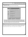
1 Click the Flow Control tab. Figure 23 shows the default settings.
Figure 23
2 Check the flow control settings of the device that you are connecting to the ECB. Change the
ECB settings to match those of the connected device by clicking the corresponding buttons.
Again, as with the UART settings, flow control only works when both devices are using the
same settings. For example, if you are connecting to a device that is using RTS/CTS hardware
flow control, set the ECB hardware flow control settings to RTS/CTS.
Serial Packets
The parameters under the Packets tab control the serial-to-network packet conversion process. Most users will not
need to change the serial packet parameters. These parameters control the way that data received on the serial
port is divided into Ethernet packets. The Ethernet packets are sent to a serial application network connection.
For specific information about the effects of the serial packet parameters, see Appendix B.
29
9
Configuring Wireless Printing to a Serial Printer
This chapter describes how to configure the 3Com ECB to enable wireless printing to a serial printer.
NOTE: If you have an Ethernet printer, this chapter does not apply. To connect to an Ethernet
printer, follow the instructions for configuring a wireless Ethernet bridge in Chapter 6.
The LPD protocol requires an operating system (such as Windows and Linux) that supports LPD to a remote
host. The LPD server on the ECB uses a uni-directional protocol wherein data is received via a network
connection and sent out the serial port to the printer. Data received from the serial port is ignored. This
means the ECB ignores data received from the printer except for software flow control characters (refer to
“Software Flow Control” in Chapter 8).
NOTE: When configuring your operating system, use the network hostname or IP address of the ECB
as the remote printer host.
1 Complete the Basic Radio Configuration instructions described in Chapter 5.
2 Complete the Network Configuration described in Chapter 7.
3 Complete the General Serial Configuration described in Chapter 8.
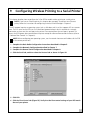
4 Click the Serial tab, and then select the Protocol tab as shown in Figure 24.
Figure 24
5 Click LPD.
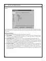
6 Click the Flow Control tab (Figure 23). Verify that the flow control settings of your ECB match
those of your printer.
31
9
Configuring Wireless Printing to a Serial Printer
NOTE: If the flow control settings do not match, there will likely be errors when printing. Refer to your
printer manual for information on how to configure flow control settings in your printer.
7 Finish the configuration by clicking Update And Reset Unit. Your ECB is now configured to act
as an LPD print server for your serial printer.
32
10
Serial Line Replacement
Two 3Com ECBs are required to perform wireless serial line replacement. Serial line replacement can operate
with the radio in either infrastructure or ad hoc mode.
When performing serial line replacement, data is exchanged using one of two protocols:
■ RMP Pipe
■ TCP Pipe
RMP Pipe is generally used in situations that require real-time or high-reliability data transfer. TCP Pipe is
useful in situations where ECBs are moving in and out of range from each other. RMP Pipe is preferable for
most serial line replacement applications.
RMP Pipe
For applications where an RS-232 serial cable is being replaced by a pair of ECB units or when ECB units are
being used to form a broadcast topology, the RMP Pipe protocol should be used. In the RMP Pipe protocol,
the ECB accepts a stream of data at its serial port and transmits it over the network to one or more receiving
ECB units. When the data arrives at the receiving ECB, it is sent is out the serial port of that ECB.
The RMP Pipe protocol sends data to the receiving unit as though the ECB units were directly connected via
serial cables. The data is not filtered or interpreted by either of the ECB units. This protocol is most useful if
the ECB is to be used as a drop-in replacement for a serial cable.
The RMP Pipe protocol has several configuration options that are designed to optimize data throughput and
minimize packet loss according to the needs of your particular system.
Configuring RMP Pipe
1 Complete the Basic Radio Configuration instructions described in Chapter 5.
NOTE: If you are replacing a serial line or serial network with two or more ECB units without using an
access point, be sure your radio is using ad hoc mode.
2 Complete the General Serial Configuration described in Chapter 8.
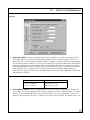
3 Click the Serial tab, and then select the Protocol tab as shown in Figure 25.
4 Select RMP Pipe.
5 Click the RMP Pipe tab.
6 Configure the RMP pipe parameters using the following section as a guide.
33
10
Serial Line Replacement
Figure 25
In environments where there are only two ECB units being used, you do not need to change these settings
from their default values. The default values allow two units to automatically detect each other and establish
a connection.
RMP Pipe Parameters
The defaults for the following RMP Pipe parameters are shown in Figure 26.
■ Source Address – This is the RMP address the ECB uses to identify itself when sending serial data to
another ECB. A value of default will cause the ECB to use its unique serial number as the RMP address.
It is unlikely you will need to change this setting.
■ Source Address Filter – Setting this value will tell the ECB to accept data coming only from the
specified address. For example, if this entry is set to 1234, only data originating from a ECB with the
RMP address of 1234 will be accepted. All other data will be ignored. The value none allows data from
any RMP address to be accepted. The Source Address Filter value needs to be changed only if you have
multiple RMP passthrough serial line replacement installations in close proximity.
■ Destination Address – This address tells the ECB where to send data received on the serial port. You
may enter the RMP address of another ECB for direct serial line replacement. Other possible values are
dynamic or broadcast. Entering dynamic causes data to be sent to the ECB from which the unit last
received data. Using the value of dynamic is an easy way to allow two ECB units that are by themselves
to communicate to each other. Entering broadcast causes the data to be sent to all ECB devices that are
set to use RMP Pipe.
34
10
Serial Line Replacement
Figure 26
■
Transmit Try Count – For non-broadcast data, this count specifies the number of attempts that the
ECB should make in transmitting each RMP packet of data. A transmission attempt may fail if the
destination ECB is out of range or turned off. When this happens, the data will be lost if retry attempts
are not made, or are not successful. The Transmit Try Count gives the user the ability to tell the ECB how
diligently to attempt transmission of data. Note that subsequent RMP data transmissions are delayed
until the packet being retried is successfully sent, or the maximum try count is reached. The maximum
count is 65,000 times. The default value is infinite, which causes each packet to be retried until
successfully sent. Select the Transmit Try Count based on the sensitivity of your application to data delay
and/or data loss (Table 3):
Table 3 Transmit Try Count Setting
■
Application Sensitivity
Transmit Try Count Setting
Sensitive to data delay
Low transmit try count
Sensitive to data loss
High transmit try count
Transmit Retry Interval – When making additional transmit attempts as specified with Transmit Try
Count above, it is necessary to specify how long to wait between successive retry attempts. This setting
determines the time period between retransmission attempts. The value is specified in 1/100ths of a
second, so that a value of 100 means 1 second. The maximum value is 65000. The default value is 100.
35
10
Serial Line Replacement
I/O Control
I/O control is only relevant to serial line replacement applications that use the RMP protocol. I/O control defines
control over digital inputs and outputs of the ECB separately from the data lines. Digital input and output are
shared with the flow control lines (RTS, DTR, CTS, and DSR), but in this mode the ECB does not interpret them
as flow control signals. They give the ability to send digital data from one device to another without
interpretation by the ECB units themselves. When a ECB detects a change in one of its RTS or DTR lines, it will
cause the opposite ECB to immediately change the state of its corresponding CTS or DSR line to match.
NOTE: You cannot use hardware flow control on lines that have been enabled for I/O Control.
TCP Pipe
TCP Pipe, like RMP Pipe, makes no changes to the serial data stream. TCP Pipe differs from RMP Pipe in that it
creates two independent TCP/IP network connections for transmitted and received data. Using two
connections allows each ECB to detect conditions when it has lost radio contact with the opposite unit, as
can occur in environments with mobile units.
Configuring TCP Pipe
In this configuration, each ECB unit simultaneously acts as a client and a server.
1 Complete the Basic Radio settings as described in Chapter 5.
NOTE: If you are replacing a serial line or serial network with two or more ECB units without using an
access point, be sure your radio is using ad hoc mode.
2 Complete the Network Configuration described in Chapter 7.
3 Complete the General Serial Configuration described in Chapter 8.
4 Click the Serial tab.
5 Select the Protocol tab.
6 Select TCP Pipe (Figure 27).
36
10
Serial Line Replacement
Figure 27
7 Click the TCP Pipe tab (Figure 28).
Figure 28
8 Set the Listen on port number for each unit to match the Connect to port number of the
opposite unit. The defaults for both of these ports are set to 4000 ensuring a correct
configuration if both ECBs are left at the default value.
37
10
Serial Line Replacement
9 Enter the IP address of the opposite unit in the Connect to IP field.
There are twoReconnect after shutdown check boxes (which are checked by default) for both
the listening port and connecting port numbers. This feature allows the ECB units to reestablish communication after one of the ECB units has lost communication with the other.
For example, if one of the ECB units is power-cycled or loses radio communication for a time,
the unit will reconnect only if this feature is enabled.
10 Click Update And Reset Unit.
38
11
Configuring the ECB as a Network Serial Port
Connection to a network serial port is accomplished over a TCP/IP socket connection. Any program that uses
standard TCP/IP network sockets may be used to communicate with the serial port of the ECB. Once a socket
is established to the ECB, any data written to the socket will be sent out the serial port of the ECB. At the
same time, any data received by the serial port of the ECB will be returned via the socket connection.
The ECB network serial port may be used in two modes:
■
■
TCP Listen Port
TCP Connect Port
In the TCP Listen Port mode, the ECB waits for a TCP/IP socket connection to be made by the network
program with which it will communicate. TCP Listen Port mode should be used if you have a central server
that expects to open a TCP/IP socket connection to the ECB.
In the TCP Connect Port mode, the ECB will establish a socket connection to the IP address and port number
specified in the configuration. TCP Connect Port mode should be used if your system expects the ECB to
open a TCP/IP socket connection to a central server
To configure your ECB as a network serial port, begin by following the steps below.
1 Complete the configuration of the Basic Radio settings as described in Chapter 5.
2 Complete the Network Configuration described in Chapter 7.
3 Complete the General Serial Configuration described in Chapter 8.
4 Click the Serial tab, and then select the Protocol tab. TCP Listen Port and TCP Connect Port will
appear among the protocol choices displayed (Figure 29). Continue following the instructions
below for the mode of your choice.
Figure 29
39
11
Configuring the ECB as a Network Serial Port
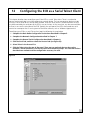
TCP Listen Port
Complete the configuration described in steps 1–4 at the beginning of this chapter and then follow the steps below:
1 Click TCP Listen Port from the Protocol list (Figure 29)
2 Click the Listen tab (Figure 30).
3 Type the port number on which the ECB will listen for a connection. This is the port number
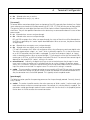
that your program will use to connect to that ECB. The default is 4000.
4 For most applications, leave the Reconnect After Shutdown box checked. Checking this box
causes the ECB to listen for and accept a new connection if the active one closes.
5 Click Update And Reset Unit.
Figure 30
40
11
Configuring the ECB as a Network Serial Port
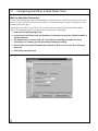
TCP Connect Port
Complete the configuration described in steps 1–4 at the beginning of this chapter, and then follow the steps below:
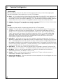
1 Click TCP Connect Port from the Protocol tab list (Figure 31).
Figure 31
2 Click the Connect Port tab (Figure 32).
3 In the Connect to IP field, enter the IP address of the device that the ECB is connecting to.
4 In the Connect to Port field, type the port number to which the ECB will connect. The default
is 4000.
5 For most applications, leave the Reconnect After Shutdown box checked. Checking this box
causes the ECB to re-initiate a new connection if the active one closes.
6 Click Update And Reset Unit.
41
11
Figure 32
42
Configuring the ECB as a Network Serial Port
12
Configuring the ECB as a Serial Telnet Client
This chapter describes how to configure your 3Com ECB as a serial Telnet client. Telnet is a method to
connect and remotely log-in to a host computer or network device. The host computer or device must be
running a Telnet server for this service to be available. Once the Telnet session is established from the ECB,
any data received by the serial port of the ECB is sent to the host. At the same time, any data returned from
the host is sent out the serial port of the ECB. Typically, the serial port of the ECB is connected to a serial
terminal or a computer that is running terminal emulation software, such as Windows Hyperterminal.
To configure your ECB as a serial Telnet client, begin by following the steps below:
1 Complete the Basic Radio Configuration instructions described in Chapter 5.
2 Complete the Network Configuration described in Chapter 7.
3 Complete the General Serial Configuration described in Chapter 8.
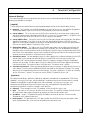
4 Click the Serial tab, and then select the Protocol tab (see Figure 33).
5 Select Telnet in the Protocol list.
6 Click the Telnet tab at the top of the panel. There are two methods that can be used to
establish a Telnet connection, wait for keystroke and command prompt. The next two sections
describe these methods and the configuration necessary for each.
Figure 33
43
12
Configuring the ECB as a Serial Telnet Client
Wait for Keystroke Connection
The wait for keystroke connection method establishes a connection to a specific Telnet host when the user
presses a key on the Telnet terminal window. When the Telnet connection is closed, the ECB will wait for a
keystroke to connect again.
To configure your ECB as a serial Telnet client using the wait for keystroke connection method, follow
steps 1–6 at the beginning of this chapter and then complete the steps below:
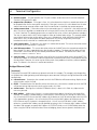
1 Click wait for keystroke (Figure 34).
2 In the Connect to IP field, enter the IP address of the device to which the ECB will establish a
Telnet connection.
3 The default Connect to Port value, 23, is the industry standard port number for Telnet
connections. It is unlikely you will ever need to change this setting.
4 Leave the Reconnect After Shutdown box checked to allow a new session after closing an
active one.
5 Click Update And Reset Unit.
Figure 34
44
12
Configuring the ECB as a Serial Telnet Client
Command Prompt Connection
The command prompt connection method provides a "Telnet prompt" to the serial terminal. From the Telnet
prompt, a user can open a Telnet session to any computer or device that is accessible on the network and is
capable of accepting Telnet connections.
To establish a Telnet connection from the terminal emulator software, type the command open followed by
the IP address of the host computer or device. The IP address may optionally be followed by the TCP port
number on which to open the connection. If the port number is omitted, the industry-standard default Telnet
port number of 23 is used.
NOTE: You must use the IP address and not the name of the host since only IP addresses are recognized
by the ECB. You can usually determine the IP address of a host by pinging its host name.
When the Telnet connection is closed, the ECB will present a new Telnet prompt.
To configure your ECB as a serial Telnet client using the command prompt connection method, follow steps
1–6 at the beginning of this chapter and then complete the steps below:
1 Click command prompt (Figure 35).
2 Click Update And Reset Unit.
Figure 35
45
13
Troubleshooting
If your 3Com ECB is not operating properly, please make sure the ECB is running the latest firmware, and use
this guide before contacting 3Com Customer Support.
Firmware Updates
Firmware updates can be found at the 3Com Customer Support Web site: http://www.support.3com.com
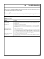
Problem Diagnosis
Table 4 Problem Diagnosis
Problem
Solution
Power light is off or the power
light is blinking.
The ECB is not receiving power properly.
Alert light is on.
Configuration or software alert condition.
Verify that all physical connections are securely in place. Contact Customer Support if the
problem persists.
Check the System Event Log to determine the cause, and refer to Section 13.2, Event Log
Error Table for details. Use the Clear Event Log option to clear the event log and turn off
the status light.
ECB is connected to an
Ethernet cable, but the
Ethernet Link Light is not lit.
Invalid connection to Ethernet.
Wireless light is off and the
Alert light is off.
The PC Card is not linking to the access point.
Verify that both ends of the cable are plugged in securely. If the ECB is attached to a hub, a
crossover Ethernet cable must be used. If the ECB is attached directly to an Ethernet device
(i.e., a PC or Ethernet printer), it must be a straight-through cable. Verify that you are using
the correct cable. If you are using the correct cable, verify that you are connecting the ECB
to a 10BASE-T Ethernet device. The ECB does not support 100BASE-T.
Verify that the ESSID is set to match the access point ESSID. Verify that the PC Card is fully
inserted in the socket.
47
13
Troubleshooting
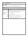
Event Log Error
Table 5 lists event log errors. All entries in the event log are preceded by a number. This number is a
timestamp used by Customer Support, but is not relevant to looking up items in Table 5.
Table 5 Event Error Log
Error Code
Description
UART Error – No Rx Buffer
Available
Data is being sent to the UART at a rate faster than it can clear its receive buffers, and data is
being lost.
Enable flow control for your serial application. Note that if you are using the serial port menu
system for configuration, flow control will not be enabled in the ECB. To avoid getting this error
while in the serial port configuration system, simply type slower.
FLASH failure. Unable to
read or write
configuration.
FLASH may be damaged. Configuration cannot be accessed or saved.
Initialization of interface
"lan0" failed.
PC Card could not be initialized.
Contact 3Com Customer Support.
Try each of the following steps in order. If any of these steps succeed, there is no need to
perform any of the later steps; otherwise continue to the next step.
1
2
3
4
48
Reset the ECB.
Unplug the power, wait for approximately 30 seconds and then reapply power.
Reset the ECB to the factory default configuration and reset the ECB.
Contact 3Com Customer Support if the problem persists.
A
Terminal Configurator
The Terminal Configurator is an alternate method that can be used to configure your 3Com ECB. It can be
used in the event that the ECB Configuration Utility (Chapter 3) is not available. The Terminal Configurator is
a text-based configuration method that lacks many of the features of the Configuration Utility. The Terminal
Configurator can be accessed in two ways.
The Terminal Configurator can be used via a direct serial connection. When using a direct serial connection, the
ECB communicates with a serial terminal or a computer that is running terminal emulation software. Some
common examples of terminal emulation software include Hyperterminal, ProComm, and Telix. Configuration
using a direct serial connection can be performed at any time, regardless of the current ECB settings.
The Terminal Configurator can also be used over a Telnet connection. When using a Telnet connection, the
unit communicates using TCP/IP with a computer running a Telnet program. A Telnet connection can be used
to configure ECB units outside of your local area network, when the configuration utility cannot be used,
because the TCP/IP communication is route-able.
Establishing a Direct Serial Connection
This method of configuring and managing an ECB uses a serial cable connected from the ECB to a computer
running terminal emulation software. Hyperterminal is one of the most widely used terminal emulation
programs because it is standard software included with all recent Windows-based PC’s. Use the following
instructions to configure your ECB using the Hyperterminal program.
1 Complete steps 1-10 of the hardware installation procedure in Chapter 3.
2 Connect a serial cable to your computer’s serial port. Make note of the PC’s COM port you
plugged this cable into. Plug the opposite end of the serial cable into the Serial port on the ECB.
3 On your desktop, click the Start icon.
4 Click Programs.
5 Click Accessories.
6 Click Hyperterminal.
7 Double-click the file labeled Hypertrm.exe.
8 The Connection Description screen will appear. This screen allows you to insert a connection
name into the Name field. This name can be any alphanumeric combination.
9 In addition, the Connection Description screen has an Icon field. Leave the highlighted icon at
its default setting.
10 Click OK to proceed using Hyperterminal. Use the Cancel button to terminate Hyperterminal.
11 The Phone Number screen appears next. The Country Code, Area Code, and Phone Number
fields should be blank by default. Leave these fields at their default settings.
12 In the Connect Using field, choose the COM port that you plugged the RS-232 cable into from
the pop-up box options.
13 Click OK. The COMx Settings screen will appear.
14 Select 9600 in the Bits per second field. Leave the default of 8 selected for the Data Bits field.
Parity should be left at its default of None. The Stop bits setting should be left at its default of 1.
49
A
Terminal Configurator
15 Choose None for the flow control option.
NOTE: The serial port settings needed for use by the Terminal Configurator will always be exactly as
described here, regardless of the General Serial Settings (Chapter 8).
16 Click OK after all of the COM settings have been chosen.
17 The next screen will appear blank. To bring up the Configuration Utility, insert one end of an
extended paper clip into the small hole labeled Config. (located next to the Serial port on the
ECB) to push the configuration button (Figure 10).
18 The Terminal Configurator will appear on the screen. You have now successfully opened a
direct serial connection to the Terminal Configurator!
19 If the ECB does not respond within a few seconds after pressing the configuration button and
is connected to power, disconnect power for a few seconds, then reconnect power and press
the configuration button again. If the terminal displays random characters, check the baud
rate and bit settings in your terminal emulation software to insure 9600 baud, 8 data bits, no
parity, and 1 stop bit.
NOTE: If, after performing the above step, the ECB does not respond with the configuration mode
main menu, verify that there is not a cable problem by observing the amber Serial TX LED when
pressing the Enter key on the PC. Each time the key is pressed, the Serial TX light should blink faintly
and quickly. If the Serial Tx light is not blinking, there may be a problem in the cable connection. If the
Serial TX light blinks when the Enter key is pressed and the unit does not respond, check to see if the
serial configuration is set to 8 data bits, no parity, 1 stop bit.
Establishing a Telnet Connection
This method will open a Telnet connection to the Terminal Configurator on port 23, which is the default for
most Telnet programs. However, this only works after the ECB has been assigned a TCP/IP address. If you
need to assign the ECB an IP address, you will need to use either the Configuration Utility or the Terminal
Configurator using a direct serial connection.
1 Click Start.
2 Click Run…
3 Type: telnet xxx.xxx.xxx.xxx
- where xxx.xxx.xxx.xxx is the IP address of the unit you wish to configure.
4 The Terminal Configurator will appear on the screen. You have now successfully opened a
Telnet connection to the Terminal Configurator.
50
A
Terminal Configurator
Using the Terminal Configurator
Once you have established a connection to the Terminal Configurator, you will see the Main menu.
1 Once the Main menu is displayed, use the arrow keys to move the highlighted bar. If the arrow
keys don not work, you can move the bar by holding down the Control key while pressing N
(for Next) and P (for Previous) to move the bar. To select an entry, press the Enter key.
2 To modify the configuration, as described in the following sections, select the menu item Edit
configuration. Another menu, listing available files to edit, will then display. Selecting one of
the available files will bring up an editor that you can use to modify the file. File selection and
editor operation are described below.
3 After you have finished configuring the ECB, select Reset the Unit, and then answer Yes to the
confirmation. This will reset the device, allowing the new configuration to take effect as well
as place it into operating mode. Now you are ready to use your new configuration.
Main Menu Overview
■
■
■
■
■
■
■
■
■
■
Resume operation
This option exits Configuration. It returns the ECB to the settings the ECB had before the Configure
button was pressed.
Edit configuration
Brings up a list of files to edit. Descriptions of the files and their contents are below.
View configuration for capture
If you select this option, it will give you an opportunity to enable capture mode in your terminal
software. It will then display all configuration settings and give you the option to disable capture mode.
This option can be used to keep a record of the settings made for a particular ECB unit, or to generate a
file for 3Com Customer Support if you have any difficulties.
Reset configuration to default
Sets all configuration files to their factory default. A confirmation dialog box to verify previous selection
so changes may or may not take place.
View forwarding database
Lists the MAC addresses of all network nodes detected, and the network interface of which they were
last listed.
View roaming log
Lists the MAC addresses of the access points the ECB has had association/disassociation.
View system error log
Shows a list of errors if any have occurred. Use this option if the ECB Status LED is lit to see what kind of
message the ECB is generating. See Section 13.2 for a list of messages.
Clear system error log
Removes all messages from the error log described above.
Reset the unit
Performs a hardware reset. Use this after making configuration changes to allow the changes to take effect.
Edit Configuration Menu
The Edit Configuration menu contains three or four selections.
51
A
■
■
■
■
Terminal Configurator
Return to Main Menu
Goes back to the previous menu selections.
System
Brings up the editor screen with the configuration file for options that are not communication dependent.
RS-232 port (uart0)
Brings up the editor screen with the configuration file for the serial port and per-connection network settings.
Bridged Ethernet (lan0)
Brings up the editor screen with the configuration file for the radio parameters and IP network
interface settings.
Using The Editor
Selecting one of the configuration files above will bring that file into the editor. Once inside the editor, you
may use arrow keys to move the cursor around. If the arrow keys do not work with your terminal emulator,
use Ctrl+P for up [previous], Ctrl+N for down [next], Ctrl+B for left [back], and Ctrl+F for right [forward] for
cursor motion.
For faster motion, you can use Ctrl+A to jump to the beginning of the line, and Ctrl+E to jump to the end.
(People familiar with the Emacs editor should feel at home with these keystrokes.)
To make changes in the editor, simply move the cursor to the point you want to change and type. Deleting
text behind the cursor can be done by moving the cursor to the position immediately following the character
to remove and press either the Backspace or Delete keys, or type Ctrl+H. To delete text in front of the cursor,
press Ctrl+D. To delete text from the cursor to the end of the line, press Ctrl+K.
After editing is completed, please save these changes by pressing Ctrl+W. After the changes are saved, the
Edit Configuration menu will then return to the screen. Although changes will be saved, they will not take
effect until you power the ECB off and back on. If you decide that you do not want to save the changes you
have made, press Ctrl+X. It will ask for confirmation, then returns to the Edit Configuration menu.
If while typing the screen display becomes corrupted or confused, press Ctrl+L to force a screen redraw.
Corruptions or confusions may occur due to many terminal emulation software packages not emulating
VT100 correctly.
52
A
Terminal Configurator
Configuration File Format
People familiar with the Windows WIN.INI file format will recognize the format of the file. It is broken down
into sections that define a particular grouping of options. Each section contains a section header at the top
which is a string of text surrounded by square brackets: [ ]. This is the section title. After each section header,
there is a list of entries containing equal signs. The text before the equal sign is a key and the text after the
equal sign is the value. Changing the value of different keys is how configuration changes are performed. For
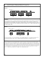
example, here are the first two lines of the uart0 RS-232 file:
[hardware]
baud = 9600
In this example, [hardware] is the name of a section. Until the next section name in the file, all entries must be
either key/value pairs (such as the "baud = 9600" entry) or comments. Key/value pairs listed before a section
name are invalid.
Comments may be stored in the configuration file by inserting a pound sign (#) before the text to be added.
This allows room for an explanation as to why certain settings have been made, who made the changes, etc.
Anything may be written in a comment, but the comment ends at the end of the line. Multi-line comments
are done by inserting the # at the beginning of each line. For example:
# This is a comment.
# This is line #2 of the comment.
this = no comment
# But this is one.
File Contents
System
[configure]
This contains settings that pertain to the operation of the Configuration menus. Currently, there is only
one: password.
■ password
This allows the setting of a password that will be asked for upon entry to the
Configuration screen. Up to 12 alphanumeric characters will be accepted. Do NOT use any characters
other than numbers and letters in this password. Although the password is not hidden from the screen
while editing, it will be hidden when entering configuration.
[bridge]
Bridge gives variables that are common to all radios. Bridge affects the behavior of radios.
■ AP refresh period
Periodically a ECB will ping an access point. AP Refresh Period is the time, in units
of seconds, between pings. The default for this value is 60 (which should be left at this default). If this
default is changed, there is a chance that the access point will ignore the ECB unit; therefore, the unit
will not be found on the network.
53
A
Terminal Configurator
NOTE: Having this refresh period active will not hamper the performance of the ECB.
RS-232 Port (uart0)
[hardware]
RS-232 serial UART configurations found on all UARTS.
■ baud
This selects the data transfer rate of the RS-232 serial port. The baud rate can be anywhere
between 112.5 and 115,200 bps. All standard rates (300, 1200, 2400, 9600, 19200, 38400, 57600,
and 115200) are clocked precisely, but values in between will be rounded to the closest possible
hardware setting.
NOTE: Closest possible hardware setting does not mean that the value will be rounded to one of the
standard rates. The ECB’s UART is fully capable of operating at non-standard speeds. The resolution of
possible baud rates is smaller at lower baud rates than at higher baud rates.
■
■
■
data bits In a UART character frame, this selects the number of bits that are used to transmit data.
Possible values are 7 and 8.
parity This sets the parity used in the UART character frame to check for correct data transmission.
Options are none, odd, and even.
stop bits Selecting the number of bits used to represent an end of character bit in the UART frame.
The value can be 1 or 2.
[software]
The [software] section is used to control the receiving and sending of bytes over the serial port. Proper
setting of these values can significantly enhance the efficiency of data transmission because the radio is
"packet-based" and the UART is "stream-based."
Stream-based data means that the data is transmitted and received one byte at a time, without any
mechanism to separate chunks of data from other chunks of data. The devices generating and using the
data produced by the stream-based packet determines how the data is delimited. Additionally, the devices
also determine the meaning of the packet.
Packet-based data means that the data is grouped into chunks, and then wrapper information is added to
this data specifying the destination of the data. Computer networks are packet-based by design. The radio
in the ECB is really a computer network interface, so the ECB’s radio is packet-based.
This becomes important as the data is moved between the UART and the radio. When data is received over
the radio, sending it to the UART is simple. The wrapper information is removed and the data inside the
wrapper is sent out the serial port as fast as it can go. However, data being received over the serial port
must be converted into packets.
In order to perform this conversion, the ECB must be given a set of rules that tell it that it is okay to start
transmitting the data already received. The data cannot be transmitted as soon as it is received, because as
explained earlier there is overhead in the radio transmitting process. The values in this section define these
conversion rules.
54
A
Terminal Configurator
NOTE: These rules do not change the data in any way. They simply specify when data can be
transmitted over the radio.
■
■
■
■
line length Data is transmitted over the radio once the maximum number of characters has been
achieved. The line length default is 1408. Once 1408 characters have been received by the UART, these
characters of data will be transmitted regardless of the content of the data. This value can range from 1
to 1408, but be cautious of using values too small for they could result in data loss.
input timeout How long the ECB will wait after some data has been received on the UART before
giving up on waiting for more. Once a character has been received the timer starts with this timeout. If
the timer expires, the data is considered to be complete and gets transmitted immediately. Conversely, if
another character is received before this timeout, the timer is restarted from the beginning. The range
for this value is from 10 to 65536 milliseconds, though it will always round up to the nearest tens of
milliseconds. For instance, setting the timeout to 55 will mean the ECB will wait for 60 milliseconds
before giving up and transmitting the data.
delimiters Special characters that specify the end of the data. Once any of the characters listed in this
option are received, the data is transmitted immediately. In serial communications, there is frequently a
character reserved to mean "end of transmission". In human-interface applications, this character is the
"newline" or Enter key. For computer to computer communication, this value may be different. If one
exists, adding it to this list will greatly improve communication efficiency. Up to four delimiters can be
listed here. They are specified as a space separated list of ASCII values. The values can be written as
decimal or hexadecimal numbers.
protocol Data format of the communication between the UART and radio network is defined by the
[protocol]. Possible values are passthrough, passthrough2, telnet, and LPD.
■
Passthrough forwards any data received over the UART or radio interfaces to the other interface with
the data unchanged.
■
Passthrough2 operates much like passthrough, but opens a socket in each direction so that if a ECB
loses power, it can re-establish communications much faster when power returns.
■
Telnet gives a prompt similar to that of the Telnet application found on UNIX systems. Telnet also
interprets the data received over the radio, removing special character sequences known as "DO"
and "DONT" requests.
■
LPD is a UNIX print serving protocol. LPD received data in a particular format over the radio, and
converts it into the data stream that should be sent to the printer. Data sent by the printer is ignored.
NOTE: When setting up to use LPD, set the printing parameters so that the file is sent off using the ECB
as the remote host. Any remote printer name can be used so long as it fits within the guidelines for
naming a printer.
55
A
Terminal Configurator
[flow control]
The ECB supports the following six flow control options: Recognize RTS, Generate CTS, Recognize DTR,
Generate DSR, Recognize XON/XOFF, and Generate XON/XOFF. It also supports the original RS-232
specification for flow control where CTS is generated only when RTS is asserted. These options are
explained below.
The incoming flow control options specify what method of communication is used between the ECB and
the device it is communicating with over the RS-232 cable to instruct the ECB when to start and stop
sending data. Since the ECB is a DCE (Data Communications Equipment) device, the three methods of
incoming flow control are software (also known as XON/XOFF), RTS (Request To Send), and DTR (Data
Terminal Ready). These three methods are all signals that the host computer sends to the ECB when it
either has too much data to work with and wants the ECB to stop sending, or when it does not have
enough data and wants the ECB to start sending what it has.
Software flow control is implemented as two specific characters that are sent on the wire embedded with
the data. RTS and DTR are signals that have their own wires, independent of the data wires.
The outgoing flow control options specify the method of communication that is used between the ECB and
the host computer. This communication instructs the computer to start and stop sending data. The host
computer is a DTE device (Data Terminal Equipment), thus uses software CTS (Clear To Send), and DSR
(Data Set Ready) as its flow control signals. The aforementioned signals are sent to the host computer while
its buffers fill and empty by the ECB.
Software flow control works the same outgoing as it does incoming. CTS and DSR work the same way RTS
and DTR do as well.
When one communicator wants the other to stop sending data, it can use as many of the flow control
options as necessary to communicate its request to the other side. Selection for software is flow control is
made during the configuration.
For both incoming and outgoing flow control use the words yes and no to enable or disable recognition.
There is one additional allowed value for the CTS entry. This value is RTS. This may seem confusing, but
originally the UART protocol was only defined to restrict data flow in one direction and that would be from
a modem to the host computer. Originally, the modem would be allowed to send data to the host
computer at any time. (The modem which does not have any buffering capabilities would loose data if the
data was not sent to the host immediately; otherwise, all of the data thereafter would be lost.) The host
computer, however, would have to ask permission from the modem to send data. The host would do this
by asserting the RTS line. The modem would see this, and check to see if it were ready to accept data. If so,
it would then assert the CTS line, thus giving it permission. Once the host computer finished sending the
data, it would drop the RTS line and the modem would subsequently drop the CTS line.
This is the behavior that is emulated when RTS is used as the value for the CTS entry. Note that this is
obsolete behavior, and most devices are designed for RTS to really mean flow control in the computer’s
direction. But the ability is there if you have older equipment. Also note, if this setting is chosen, then set
the RTS entry to no since that line will not have the meaning of incoming flow control.
■ incoming software
Allowed values are yes and no.
■ rts
Allowed values are yes and no.
■ dtr
Allowed values are yes and no.
■ outgoing software
Allowed values are yes and no.
56
A
■
■
Terminal Configurator
dsr Allowed values are yes and no
cts Allowed values are yes, no, and rts.
[i/o control]
I/O control defines control over digital inputs and outputs of the ECB, separately from the data lines. Digital
input and output are shared with the flow control lines (RTS, DTR, CTS, DSR), but they are not flow control.
They give the ability to send digital data from one ECB to another without interpretation by the ECBs
themselves. They can also provide information to the device they are connected to about the status of lowpower modes.
■ rts
Allowed values are none and passthrough.
■ dtr
Allowed values are none and passthrough.
RTS and DTR are output lines. When set to passthrough, the status of these lines will be forwarded to
the ECB unit specified by the "socket" option described below. When set to none, they do not function
as digital inputs.
■ cts
Allowed values are negate, assert, and passthrough.
■ dsr
Allowed values are negate, assert, and passthrough.
CTS and DSR are output lines. When set to negate or assert, they will output a continuous digital value.
The value negate outputs a logic 1, or "mark" which is electrically negative. This is also the state seen
on an RS-232 connector when the cable is unplugged. The value assert outputs a logic 0, or "space"
which is electrically positive. When set to passthrough, CTS will output the value that the remote ECB is
receiving on its RTS line, and DSR will output the remote DTR value. The source of these remote signals
depends on the remote ECB’s "socket" setting in this section.
■ resend interval
Ordinarily, the digital input lines are transmitted whenever they change. In some
cases (such as when the remote unit is turned off and then on so that it forgets the previous output
states), this is insufficient. Setting this resend interval value to a non-zero number causes the state of the
input lines to be re-transmitted in a regular interval. The value of this setting is in seconds.
■ socket
This entry specifies a network connection to use to send the RTS and DTR input states to a remote
ECB. The value of this setting must be the name of a section that describes the network connection to use.
Also, the connection must use the RMP protocol. This is typically set to the rmpbind section.
[passthrough]
The following section specifies the operating parameters for the passthrough protocol. Currently, the only
entry is socket.
■ socket
The section it specifies contains the values necessary to "bind a socket," in other words, what
needs to be known to create a network connection. For example, this value by default is rmpbind. The
connection used by passthrough mode will create a socket that uses the values in the [rmpbind] section
further down in the file to create the network connection.
57
A
Terminal Configurator
[passthrough2]
With passthrough2, there are two sockets: one for incoming data (listen), and one for outgoing data
(connect). Note: Both of these sockets must use the TCP/IP protocol.
■ listen
As in the socket key for the [passthrough] section above, the value of this entry represents the
name of another section that defines a network connection. This value by default is tcpbind1a. A
later section in this file is also named [tcpbind1a]. Thus, the connection used by passthrough mode will
create a socket that uses the values in the [tcpbind1a] section to create the network connection.
■ connect
The value of this entry points to a network connection definition that initiates the connection
instead of listening for it. The default for this setting is tcpbind1b.
[telnet]
The following section specifies the operating parameters for the Telnet protocol.
■ connect
This entry dictates what kind of prompt is seen on the serial port output. The two choices
available are: wait for keystroke and command prompt. The default command prompt will give a
prompt telnet> much like Telnet software prompt on a UNIX system. From this prompt, using the
"open" command will then connect the device to a particular machine. For example, typing open
10.10.10.129 will open a Telnet session to the machine with the IP address 10.10.10.129. The
second choice wait for keystroke allows for a configuration that only connects to one machine,
requiring only a keypress to initiate the connection.
■ wait data 1
The text for this entry is to use as a prompt in wait for keystroke mode. The value is
specified as a combination of a string and ASCII values. The default value is "Press any key to connect to
host..." (The double-quote marks are a part of this value, unlike in previous examples.) Binary data can
be added by writing data as hex or decimal, outside of quote marks. For example, the ANSI clear-screen
command string (escape, left-bracket, H, escape, left-bracket, J) can be added to the front of this string
like this: 0x1b "[H" 0x1b "[J" "Press any key to connect to host..."
■ wait data 2
This entry states what text to display after the keystroke is received. The format of the
data is the same as in "wait data 1". The default is 0xd 0xa, which will move the cursor to the next line.
■ ip address
When in wait for keystroke mode, this specifies the IP address of the machine to
automatically connect to. The default is 10.10.10.129.
■ tcp port
When in wait for keystroke mode, this specifies the TCP port number to connect to
automatically. The default is port number is 23.
■ reopen after shutdown
After one connection has been completed this value will appear and ask to
connect again. The default is on.
58
A
Terminal Configurator
Network Bindings
This section describes the meaning behind each of the entries that describe network binding. Five prewritten
bindings are provided as examples.
[rmpbind]
This binding can be used for both the passthrough protocol and for the I/O control socket setting.
■ protocol
This example uses the RMP protocol so the value of this entry is rmp. RMP binding options
are described below. If you wish to use the TCP/IP protocol, skip to the next example.
■ source address
This is the value that the ECB will use to identify its serial port when sending serial
data to and receiving serial data from other ECB units. In short, this is its port address. The default value
is default, which will cause the ECB to use its serial number as the address.
■ source address filter
Setting this value will tell the ECB to only accept data coming from the address
specified. For example, if this entry is set to 1234, only data originating from a ECB with the port
address of 1234 will be accepted. All other data will be ignored that does not have the source address
filter set to a specific address. The default value is none.
■ destination address
This address tells the ECB which port address to send data received from the
serial port. It can be the port address of another ECB’s serial port, or it can be broadcast or dynamic.
Broadcast means to send the data to all of the ECB devices. Dynamic means sending the data to the ECB
from which it last received data. Dynamic has the effect of causing two ECB units that are by themselves
to communicate to each other. The default value is dynamic.
■ transmit try count
For non-broadcast data, this count specifies the number of attempts that the ECB
should make in transmitting each piece of data to a remote ECB. A transmission may fail if the
destination ECB is out of range or turned off. When this happens, the data will be lost if additional
attempts are not made. This count gives the user the ability to tell the ECB how diligently to attempt
transmission of data. The maximum count is 65,000 times. The default value is infinite.
■ transmit retry interval
When attempting additional transmit attempts as specified with transmit try
count above, it can be useful to additionally specify how long to wait between attempts. This setting
determines the time period for retransmission attempts. The value is specified in 1/100ths of a second,
so that 100 means 1 second. The maximum value is 65000. The default value is 100.
[tcpbind1a]
Four prewritten bindings, tcpbind1a, tcpbind1b, tcpbind2, and tcpbind3 are provided for TCP/IP. When
protocol is set to passthrough, only one binding is used because only one network socket is created
(tcpbind2 and tcpbind3 are passthrough binds). When protocol is set to passthrough2, two
complimentary bindings (one connect and one listen) are used (tcpbind1a and tcpbind1b are
complimentary) because a socket is created in each direction.
■ protocol
These examples use the TCP protocol, so the value of this entry is tcp.
■ type
The values in this entry can be either listen or connect. This specifies whether the ECB will wait
for a connection from another computer or attempt to initiate the connection itself.
■ ip address
Used in TCP protocol to specify the address to which to connect. Connect must be
selected for the IP address to be used.
■ local tcp port
This port defines the TCP port number that the ECB will wait for connections from
other networked devices. Listen must be selected for this port to be used.
59
A
■
■
■
■
■
■
Terminal Configurator
remote tcp port This port specifies the TCP port numbers to connect to on the remote computer.
Connect is the type for this port.
reopen after shutdown If the type is listen, this value determines whether a second connection will
be accepted after the first connection terminates. If the type is connect, this value determines whether
another connection attempt will be made if the first connection is closed by the remote computer.
socket connect data Data to be written to the connection once it is successful is the socket connect
data. The value is specified as a combination of a string and ASCII values. For example, the default value
is "Hello!" 0xd 0xa. (The double-quote marks are a part of this value, unlike in some previous examples.)
The item in quotes and the ASCII values together make up the data to be written. This example would
cause 8 bytes to be written to the socket; these are, in hexadecimal, 0x48 0x65 0x6c 0x6c 0x6f 0x21
0x0d 0x0a. In fact, the data could have been specified on this line by using exactly those eight
hexadecimal values instead of as a combination of string and hex.
serial connect data The format is the same as in socket connect data. This causes data to be written
to the UART once a connection is successful.
serial disconnect data This causes data to be written to the UART when the network connection has
been closed. This data is appended to any data already in progress. The closing of the socket will not
cancel UART transmission of any data already received over the socket. The format of this data is the
same as in socket connect data.
serial fail data If the socket connection were to fail this causes data to be written to the UART. This
should only happen in the case of a connect type where the remote machine was unavailable or refused
the connection. However, this value may be used to catch listen problems should any software problem
occur. The format is the same as in socket connect data.
Bridged Ethernet (lan0)
[hardware]
Settings for the actual ECB hardware are determined under this category. This category varies depending
on the particular radio type being used. Following are some common settings that might be found for radio
configuration.
■ network name
Determines the network to which the ECB device will be connecting. Alphanumeric
values may be used in this field.
■ ESSID
Extended Service Set Identifier, where the service set is the wireless network to which the ECB
will be connecting. Alphanumeric values may be used in this field.
■ station name
Naming of an individual ECB device (client) is done in this field. Any alphanumeric
name may be used.
■ MAC address
Media Access Control, is a unique alphanumeric address that defines each node of the
network. This address is predefined by the manufacturer. Valid values for this setting are: detect save this will make the ECB assume the MAC address of the device on the ECB’s ethernet port when the ECB
is first powered on; dynamic - this will make the ECB assume the MAC address of the device on the
ECB’s Ethernet even if the device is changed; built-in - this will use the ECB’s built-in MAC address;
otherwise, a specific MAC address can be specified by typing in the 12 character MAC address without
the colons (for example, to specify MAC address 01:23:45:67:89:ab, use: 0123456789ab). Note that
when using the ECB for wired-to-wireless Ethernet bridging, detect save or dynamic should be used.
60
A
■
■
Terminal Configurator
transmit rate Data rate at which the radio transmits is set by this field. Valid values are radio
dependent.
enable encryption Used to indicate whether WEP encryption by the radio is desired or not. Note that
if the ECB does not support setting WEP for the particular radio in use, this option will not appear.
Setting of the various encryption options is done in the [encryption] section.
[encryption]
This value is the translation of data into a secret code. Presently, encryption is radio specific.
■ transmit key
This value sets which of the following keys are used to encrypt transmitted data. The
default setting for this value is 1.
■ encryption key 1
This value is one of the keys to use for encrypting and decrypting data on the
radio. The key should be specified as either a 10 digit or a 26 digit hexadecimal number. Note that the
number should always have a 0x before the hexadecimal digits. Use 10 digits for a 64 bit key, and 26
digits for a 128 bit key.
■ encryption key 2
This value is one of the keys to use for encrypting and decrypting data on the
radio. The key should be specified as either a 10 digit or a 26 digit hexadecimal number. Note that the
number should always have a 0x before the hexadecimal digits. Use 10 digits for a 64 bit key, and 26
digits for a 128 bit key.
■ encryption key 3
This value is one of the keys to use for encrypting and decrypting data on the
radio. The key should be specified as either a 10 digit or a 26 digit hexadecimal number. Note that the
number should always have a 0x before the hexadecimal digits. Use 10 digits for a 64 bit key, and 26
digits for a 128 bit key.
■ encryption key 4
This value is one of the keys to use for encrypting and decrypting data on the
radio. The key should be specified as either a 10 digit or a 26 digit hexadecimal number. Note that the
number should always have a 0x before the hexadecimal digits. Use 10 digits for a 64 bit key, and 26
digits for a 128 bit key.
[ip]
The following sections sets the configuration of the IP protocol.
■ ip address
IP address that will be used by other computers to communicate with a particular ECB.
■ netmask
When logical ANDed with the IP address, specifies the range of IP addresses within the local
network.
■ broadcast
In the local network, this is the IP address that is used to refer to all computers
simultaneously. The default automatic will work for almost all configurations. There should be no need
to change this value.
■ route
For this network interface card, this value references section names that specify the routing
options. The default of automatic will work for most configurations.
■ gateway
If present, this value specifies the IP address of your Internet router or firewall. By default,
this value is set to none. Change this value to the IP address of your gateway if you intend to use an
Internet router or firewall.
61
A
Terminal Configurator
Terminal Configurator Error Codes
Table 6 Terminal Configurator Error Codes
Error Code
Description
Xxxx: [yyyy]:
Section named yyyy in configuration file named xxxx was missing.
section does not exist
Save your current configuration (if applicable). Reset the ECB units configuration to Factory
Defaults. Reset the ECB. Restore configuration (if applicable).
Xxxx: [yyyy]: "zzzz":
Entry zzzz refers to a section that is not located in file xxxx.
entry refers to non-existent
section
Save your current configuration (if applicable). Reset the ECB units configuration to Factory
Defaults. Reset the ECB. Restore configuration (if applicable).
Xxxx: [yyyy]: "zzzz":
Entry zzzz in section yyyy of file xxxx was missing.
entry does not exist
Save your current configuration (if applicable). Reset the ECB units configuration to Factory
Defaults. Reset the ECB. Restore configuration (if applicable).
Xxxx: [yyyy]: "zzzz":
Entry zzzz in section yyyy of file xxxx contains an invalid value.
entry is invalid
Check the entry in the configuration for zzzz. If you cannot find zzzz in the ECB Configuration
Utility program, you may have to use the serial port or Telnet configuration menus. See
Appendix A for details.
Xxxx: <[yyyy]zzzz>:
Route values are out of range compared to the interface values.
Unable to add route.
Set the route value to "automatic." If "automatic" does not work for your ECB, check the
values you set for the route to make sure they correspond to your other IP parameters.
Xxxx: file does not exist.
Configuration file could not be found.
Reset the configuration to factory defaults, and reset the ECB. If the problem persists, contact
3Com Customer Support.
62
B
Serial Stream to Network Packet Conversion
The serial port on the 3Com ECB can be used for a range of different applications. Although the applications
can be quite different, they all involve bridging data between the ECB's serial port and one of the network
interfaces. Data that is received on the serial port is packetized, then transmitted on either the radio or wired
network interface to the network device configured to receive serial data. This chapter will discuss the
process of packetizing data received on the serial port.
Network devices transmit and receive data in a fundamentally different way than the serial port. Network
devices operate on packets whereas serial devices operate on single characters. A network packet is a welldefined structure that includes enough information for the packet to be interpreted by different network
devices, routed to the appropriate destination, and interpreted by the destination application. Each network
packet carries some amount of application data. In the case of network packets for serial port applications,
this data is the information that was received or should be transmitted on the serial port.
Data transmission between serial devices is much simpler. The most basic difference is that there is no
requirement for data to be sent in well-defined packet structures. Each device sends serial data one character
at a time. The other device must receive and process each character as it is received. Additionally, since serial
communication is always done between only two devices, there is no need to include information about the
source and destination of the data. The ECB must interpret the serial data stream, collect it into groups of
data, then form network packets with this data and transmit the packet to the network device which is set to
receive the serial information.
The ECB uses three user-configurable parameters to segment the serial character stream into groups of data
for network packets. These parameters, line length, timeout, and delimiters, are described below. Keep in
mind that the ECB always uses all three of these parameters and when the conditions of any one of them are
met a network packet is generated.
Line Length
As data arrives on the serial port it is accumulated in a buffer in the ECB. The Line length parameter sets the
maximum size for this buffer. When the number of characters in the buffer reaches the Line length value the
entire buffer is sent as the data in a single network packet. The example below illustrates a line length
of 5.The value of Line length can range from 1 to 1,408 bytes. The default value is 1,408.
NOTE: Do not use values of Line length less than 5 with a serial baud rate of 115,200 or greater.
63
B
Serial Stream to Network Packet Conversion
Figure 36
Line length = 5
a b c d e
f
g h
i
j
k
l m o
f
g h
i
j
k
a b c d e
Packet 1
data
p
Serial data
l m o p
Packet 2
data
Packet 3
data
Timeout
Often serial data arrives in small bursts of characters. When the ECB receives a burst of data it will wait for a
certain period of time for additional data to be received. If additional data is received, it is added to the
receive buffer, and the ECB begins to wait again. If additional data is not received for longer than the period
specified by the Timeout value, then the buffer of characters received is sent in a single network packet, and
the process begins again.
Figure 37
Timeout = 10 msec
>10 msec
a b
a b
Packet 1
data
<10 msec
c d e
c d e
>10 msec
>10 msec
f
g h
i
j
f
g h
i
j
Packet 2
data
Serial data
Packet 3
data
The value of timeout is in units of milliseconds, and should be specified in 10 millisecond increments. The
valid range for timeout is from 10 (0.01 second) to 65,000 (650 seconds). The default value is 10.
Delimiters
Some serial devices transmit and receive data in a known structure. In these cases there are often special
characters that the transmitting device uses to indicate a complete message has been sent. These characters
are referred to as delimiters. You can specify up to five different delimiting characters to the ECB. When the
ECB adds one of these characters to its buffer of serial received characters it will immediately send that buffer
as a network packet. The example below illustrates a data stream with delimiting characters set to be "X"
and "Y". Notice that the delimiter is included in the network packet data.
64
B
Serial Stream to Network Packet Conversion
Figure 38
Delimiters = 0x58 0x59
a b c d X e
a b c d X
Packet 1
data
f
Y
e
f
Y
Packet 2
data
g h
i
X
g h
i
X
Serial data
Packet 3
data
The value of delimiters is specified as a list of ASCII hex values separated by spaces. You may specify up to five
different delimiter values. If you are unsure of the hex value for your delimiter character, consult the Web
page www.asciitable.com for reference.
Configuration
To configure the Serial Packet parameters, click on the Serial tab and then select the Packets tab (Figure 39).
Using the descriptions in this section as a guide, enter the values for Line Length, Input Timeout, and
Delimiters specific to your setup.
Figure 39
65
C
Customer Support
3Com provides easy access to technical support information through a variety of services. This appendix
describes these services.
Information contained in this appendix is correct at time of publication. For the most recent information,
3Com recommends that you access the 3Com Corporation World Wide Web site.
Online Technical Services
3Com offers worldwide product support 24 hours a day, 7 days a week, through the following online systems:
■ World Wide Web site
■ 3Com Knowledgebase Web Services
■ 3Com FTP site
World Wide Web Site
To access the latest networking information on the 3Com Corporation World Wide Web site enter this URL
into your Internet browser:
http://www.3com.com/
This service provides access to online support information such as technical documentation and software
library, as well as support options that range from technical education to maintenance and professional
services.
3Com Knowledgebase Web Services
This interactive tool contains technical product information compiled by 3Com expert technical engineers
around the globe. Located on the World Wide Web at http://knowledgebase.3com.com, this service
gives all 3Com customers and partners complementary, round-the-clock access to technical information on
most 3Com products.
3Com FTP Site
Download drivers, patches, software, and MIBs across the Internet from the 3Com public FTP site. This service
is available 24 hours a day, 7 days a week.
To connect to the 3Com FTP site, enter the following information into your FTP client:
■ Hostname: ftp.3com.com
■ Username: anonymous
■ Password: <your Internet e-mail address>
NOTE: You do not need a user name and password with Web browser software such as Netscape
Navigator and Internet Explorer.
67
C
Customer Support
Support from Your Network Supplier
If you require additional assistance, contact your network supplier. Many suppliers are authorized 3Com
service partners who are qualified to provide a variety of services, including network planning, installation,
hardware maintenance, application training, and support services.
When you contact your network supplier for assistance, have the following information ready:
■ Product model name, part number, and serial number
■ A list of system hardware and software, including revision levels
■ Diagnostic error messages
■ Details about recent configuration changes, if applicable
If you are unable to contact your network supplier, see the following section on how to contact 3Com.
Support from 3Com
If you are unable to obtain assistance from the 3Com online technical resources or from your network
supplier, 3Com offers technical telephone support services. To find out more about your support options, call
the 3Com technical telephone support phone number at the location nearest you.
When you contact 3Com for assistance, have the following information ready:
■ Product model name, part number, and serial number
■ A list of system hardware and software, including revision levels
■ Diagnostic error messages
■ Details about recent configuration changes, if applicable
Here is a list of worldwide technical telephone support numbers. These numbers are correct at the time of
publication. Refer to the 3Com Web site for updated information.
Country
Asia, Pacific Rim
Australia
Hong Kong
India
Indonesia
Japan
Malaysia
New Zealand
Pakistan
Philippines
P.R. of China
Singapore
S. Korea
From anywhere in S. Korea:
From Seoul:
Taiwan, R.O.C.
Thailand
68
Telephone Number
1 800 678 515
800 933 486
+61 2 9937 5085 or
000800 6501111
001 800 61 009
03 5783 1270
1800 801 777
0800 446 398
+61 2 9937 5083
1235 61 266 2602
10800 61 00137 or
021 6350 1590 or
00800 0638 3266
800 6161 463
82 2 3455 6455
00798 611 2230
00798 611 2230
0080 611 261
001 800 611 2000
C
Country
Customer Support
Telephone Number
Europe, Middle East and Africa
From anywhere in these regions, call:
+44 (0)1442 435529 phone
+44 (0)1442 436722 fax
Europe and South Africa
From the following countries, you may use the toll-free numbers:
Austria
Belgium
Denmark
Finland
France
Germany
Hungary
Ireland
Israel
Italy
Luxembourg
Netherlands
Norway
Poland
Portugal
South Africa
Spain
Sweden
Switzerland
U.K.
0800 297468
0800 71429
800 17309
0800 113153
0800 917959
0800 1821502
06800 12813
1800 553117
1800 9453794
800 8 79489
0800 3625
0800 0227788
800 11376
00800 3111206
0800 831416
0800 995014
900 983125
020 795482
0800 55 3072
0800 966197
Latin America
Brazil
Mexico
Puerto Rico
Central and South America
0800 13 3266
01 800 849CARE
800 666 5065
AT&T +800 998 2112
North America
1 800 NET 3Com (1 800 638 3266)
Enterprise Customers:
1 800 876-3266
69
C
Customer Support
Returning Products for Repair
Before you send a product directly to 3Com for repair, you must first obtain an authorization number.
Products sent to 3Com without authorization numbers will be returned to the sender unopened, at the
sender’s expense.
To obtain an authorization number, call or fax:
Country
Telephone Number
Fax Number
Asia, Pacific Rim
+65 543 6500
+65 543 6348
Europe, South Africa, and
Middle East
+31 30 6029900
+31 30 6029999
Central and South America
525 201 0075
Argentina
Bolivia
Brazil
0810 222 3266
511 241 1691
0800 133266 or
55 11 5643 2700
525 201 0004
562 240 6200
525 201 0004
525 201 0004
525 201 0004
525 201 0004
511 241 1691
525 201 0004
525 201 0004
Caribbean
Chile
Colombia
Ecuador
Mexico
Paraguay
Peru
Uruguay
Venezuela
From the following countries, you may call the toll-free numbers; select option 2 and then option 2:
Austria
Belgium
Denmark
Finland
France
Germany
Hungary
Ireland
Israel
Italy
Netherlands
Norway
Poland
Portugal
South Africa
Spain
Sweden
Switzerland
U.K.
0800 297468
0800 71429
800 17309
0800 113153
0800 917959
0800 1821502
00800 12813
1800553117
1800 9453794
1678 79489
0800 0227788
800 11376
00800 3111206
0800 831416
0800 995014
900 983125
020 795482
0800 55 3072
0800 966197
U.S.A. and Canada
1 800 NET 3Com
(1 800 638 3266)
Enterprise Customers:
1 800 876 3266
70
1 408 326 7120
(not toll-free)
Index
A
D
access point 1
ad hoc topology 2
advanced radio settings, configuring 19
association log 17
data bits 27
diagnosis, problem 47
dimensions 5
direct serial connection
establishing 49
terminal configurator 49
B
baud rate 27
bridged Ethernet, terminal configurator 60
E
ECB
configuring 3
connectors 8
kit contents 3
C
cable connections 8
cap removal 6
changing
password 14
radio type 16
client (station) name 19
client bridge list screen 11
combs to prevent vibration 7
command prompt connection 45
configuration
loading 13
saving 12
configuration file format, terminal configurator 53
configuration screen 11
configuration utility
installing under Linux 9
installing under Windows 9
configuring
advanced radio settings 19
as a network serial port 39
as a serial Telnet client 43
basic radio settings 19
encryption 20
flow control 29
general serial settings 27
network settings 25
password 14
PC Card settings 19
radio type 16
RMP pipe 33
TCP pipe 36
UART settings 27
wireless printing to a serial printer 31
configuring the ECB 3
connectors 8
contents, ECB kit 3
editor, terminal configurator 52
encryption
configuring 20
error codes, terminal configurator 62
ESSID 2, 19
event log 17
errors 48
F
factory defaults, resetting to 16
firmware
updates 47
updating procedure 15
flow control 28
configuring 29
hardware 28
software 28
forward table 18
G
gateway, using a 26
GUI message log 17
H
hardware flow control 28
hardware installation 6
Hyperterminal 49
I
I/O control, serial line replacement 36
indicators, LED 5
infrastructure topology 1
installing
configuration utility 9
hardware 6
IP address 25
71
Index
L
R
LED indicators 5
Alert 5
Ethernet 5
Power 5
Serial 5
Wireless 5
loading a configuration 13
log
association 17
event 17
GUI message 17
log viewer screen 17
LPD 31
radio settings
radio type, changing 16
removing
the cap 6
the mounting plate 7
requirements, operating system 9
resetting to factory defaults 16
returning products for repair 70
RMP pipe
configuring 33
parameters 34
M
S
MAC address, forward table 18
message log 17
MIBs 67
mounting plate removal 7
saving a configuration 12
screen
client bridge list 11
configuration 11
log viewer 17
serial line replacement 33
I/O control 36
RMP pipe 33
TCP pipe 36
serial packets 29
serial settings, configuring general 27
serial stream to network packet conversion 63
serial Telnet client
command prompt connection 45
wait for keystroke connection 44
setting
baud rate 27
data bits 27
parity bit 28
stop bits 28
software flow control 28
station (client) name 19
stop bits 28
system requirements 3
N
netmask 25
network bindings, terminal configurator 59
network name 19
network serial port
configuring ECB as 39
TCP connect port 41
TCP listen port 40
network settings
configuring 25
network supplier support 68
O
online technical services 67
operating system requirements 9
configuring advanced 19
configuring basic 19
P
packets, serial 29
parameters, RMP pipe 34
parity bit, setting 28
password, changing 14
PC Card settings
configuring 19
problem diagnosis 47
T
TCP connect port 41
TCP listen port 40
TCP pipe 36
technical support
3Com Knowledgebase Web Services 67
3Com URL 67
network suppliers 68
product repair 70
Telnet connection
establishing 50
terminal configurator 50
72
Index
terminal configurator 49
bridged Ethernet 60
configuration file format 53
direct serial connection 49
editor 52
error codes 62
main menu overview 51
network bindings 59
using 51
topologies
ad hoc 2
infrastructure 1
U
UART settings, configuring 27
updating firmware procedure 15
URL 67
using a gateway 26
W
wait for keystroke connection 44
Wi-Fi compliance 3
World Wide Web (WWW) 67
troubleshooting 47
73
Warranty and Software License Agreement
3Com Corporation Limited Warranty
3Com Ethernet Client Bridge
HARDWARE
3Com warrants this hardware product to be free from defects in workmanship and materials, under normal use and service, for the following
length of time from the date of purchase from 3Com or its authorized reseller:
One (1) year
3Com’s sole obligation under this express warranty shall be, at 3Com’s option and expense, to repair the defective product or part, deliver to
Customer an equivalent product or part to replace the defective item, or if neither of the two foregoing options is reasonably available, 3Com
may, in its sole discretion, refund to Customer the purchase price paid for the defective product. All products that are replaced will become the
property of 3Com. Replacement products may be new or reconditioned. 3Com warrants any replaced or repaired product or part for ninety
(90) days from shipment, or the remainder of the initial warranty period, whichever is longer.
SOFTWARE
3Com warrants that each software program licensed from it will perform in substantial conformance to its program specifications, for a period
of ninety (90) days from the date of purchase from 3Com or its authorized reseller. 3Com warrants the media containing software against
failure during the warranty period. No updates are provided. 3Com's sole obligation under this express warranty shall be, at 3Com's option
and expense, to refund the purchase price paid by Customer for any defective software product, or to replace any defective media with
software which substantially conforms to applicable 3Com published specifications. Customer assumes responsibility for the selection of the
appropriate applications program and associated reference materials. 3Com makes no warranty or representation that its software products
will meet Customer’s requirements or work in combination with any hardware or applications software products provided by third parties, that
the operation of the software products will be uninterrupted or error free, or that all defects in the software products will be corrected. For any
third party products listed in the 3Com software product documentation or specifications as being compatible, 3Com will make reasonable
efforts to provide compatibility, except where the non-compatibility is caused by a "bug" or defect in the third party's product or from use of
the software product not in accordance with 3Com’s published specifications or user manual.
OBTAINING WARRANTY SERVICE
Customer must contact a 3Com Corporate Service Center or an Authorized 3Com Service Center within the applicable warranty period to
obtain warranty service authorization. Dated proof of purchase from 3Com or its authorized reseller may be required. Products returned to
3Com's Corporate Service Center must be pre-authorized by 3Com with a Return Material Authorization (RMA) number marked on the outside
of the package, and sent prepaid and packaged appropriately for safe shipment, and it is recommended that they be insured or sent by a
method that provides for tracking of the package. The repaired or replaced item will be shipped to Customer, at 3Com's expense, not later
than thirty (30) days after 3Com receives the defective product.
Dead- or Defective-on-Arrival. In the event a product completely fails to function or exhibits a defect in materials or workmanship within the
first forty-eight (48) hours of installation but no later than thirty 30) days after the date of purchase, and this is verified by 3Com, it will be
considered dead- or defective-on-arrival (DOA) and a replacement shall be provided by advance replacement. The replacement product will
normally be shipped not later than three (3) business days after 3Com’s verification of the DOA product, but may be delayed due to export or
import procedures. When an advance replacement is provided and Customer fails to return the original product to 3Com within fifteen (15)
days after shipment of the replacement, 3Com will charge Customer for the replacement product, at list price.
3Com shall not be responsible for any software, firmware, information, or memory data of Customer contained in, stored on, or integrated
with any products returned to 3Com for repair, whether under warranty or not.
ADDITIONAL SERVICES
Telephone Support, with coverage for basic troubleshooting only, will be provided for 90 days, on a commercially reasonable efforts basis.
Telephone support from 3Com is available from 3Com only if Customer purchased this product directly from 3Com, or if Customer’s reseller is
unable to provide telephone support. Please refer to the Technical Support appendix in the user guide for telephone numbers.
ninety (90) days
The 3Com Web site and Knowledgebase are available at no charge, and provide software and firmware upgrades, a bug list, and technical
information about 3Com products.
Warranty and Software License Agreement
WARRANTIES EXCLUSIVE
IF A 3COM PRODUCT DOES NOT OPERATE AS WARRANTED ABOVE, CUSTOMER'S SOLE REMEDY FOR BREACH OF THAT WARRANTY SHALL
BE REPAIR, REPLACEMENT, OR REFUND OF THE PURCHASE PRICE PAID, AT 3COM'S OPTION. TO THE FULL EXTENT ALLOWED BY LAW, THE
FOREGOING WARRANTIES AND REMEDIES ARE EXCLUSIVE AND ARE IN LIEU OF ALL OTHER WARRANTIES, TERMS, OR CONDITIONS, EXPRESS
OR IMPLIED, EITHER IN FACT OR BY OPERATION OF LAW, STATUTORY OR OTHERWISE, INCLUDING WARRANTIES, TERMS, OR CONDITIONS OF
MERCHANTABILITY, FITNESS FOR A PARTICULAR PURPOSE, SATISFACTORY QUALITY, CORRESPONDENCE WITH DESCRIPTION, AND NONINFRINGEMENT, ALL OF WHICH ARE EXPRESSLY DISCLAIMED. 3COM NEITHER ASSUMES NOR AUTHORIZES ANY OTHER PERSON TO ASSUME
FOR IT ANY OTHER LIABILITY IN CONNECTION WITH THE SALE, INSTALLATION, MAINTENANCE OR USE OF ITS PRODUCTS.
3COM SHALL NOT BE LIABLE UNDER THIS WARRANTY IF ITS TESTING AND EXAMINATION DISCLOSE THAT THE ALLEGED DEFECT OR
MALFUNCTION IN THE PRODUCT DOES NOT EXIST OR WAS CAUSED BY CUSTOMER'S OR ANY THIRD PERSON'S MISUSE, NEGLECT,
IMPROPER INSTALLATION OR TESTING, UNAUTHORIZED ATTEMPTS TO OPEN, REPAIR OR MODIFY THE PRODUCT, OR ANY OTHER CAUSE
BEYOND THE RANGE OF THE INTENDED USE, OR BY ACCIDENT, FIRE, LIGHTNING, OTHER HAZARDS, OR ACTS OF GOD.
LIMITATION OF LIABILITY
TO THE FULL EXTENT ALLOWED BY LAW, 3COM ALSO EXCLUDES FOR ITSELF AND ITS SUPPLIERS ANY LIABILITY, WHETHER BASED IN
CONTRACT OR TORT (INCLUDING NEGLIGENCE), FOR INCIDENTAL, CONSEQUENTIAL, INDIRECT, SPECIAL, OR PUNITIVE DAMAGES OF ANY
KIND, OR FOR LOSS OF REVENUE OR PROFITS, LOSS OF BUSINESS, LOSS OF INFORMATION OR DATA, OR OTHER FINANCIAL LOSS ARISING
OUT OF OR IN CONNECTION WITH THE SALE, INSTALLATION, MAINTENANCE, USE, PERFORMANCE, FAILURE, OR INTERRUPTION OF ITS
PRODUCTS, EVEN IF 3COM OR ITS AUTHORIZED RESELLER HAS BEEN ADVISED OF THE POSSIBILITY OF SUCH DAMAGES, AND LIMITS ITS
LIABILITY TO REPAIR, REPLACEMENT, OR REFUND OF THE PURCHASE PRICE PAID, AT 3COM'S OPTION. THIS DISCLAIMER OF LIABILITY FOR
DAMAGES WILL NOT BE AFFECTED IF ANY REMEDY PROVIDED HEREIN SHALL FAIL OF ITS ESSENTIAL PURPOSE.
DISCLAIMER
Some countries, states, or provinces do not allow the exclusion or limitation of implied warranties or the limitation of incidental or
consequential damages for certain products supplied to consumers, or the limitation of liability for personal injury, so the above limitations and
exclusions may be limited in their application to you. When the implied warranties are not allowed to be excluded in their entirety, they will be
limited to the duration of the applicable written warranty. This warranty gives you specific legal rights which may vary depending on local law.
GOVERNING LAW
This Limited Warranty shall be governed by the laws of the State of California, U.S.A. excluding its conflicts of laws principles and excluding the
United Nations Convention on Contracts for the International Sale of Goods.
3Com Corporation
P.O. Box 58145
5400 Bayfront Plaza
Santa Clara, CA 95052-8145
(408) 326-5000
Warranty and Software License Agreement
FCC Class B Statement
This device complies with Part 15 of the FCC Rules. Operation is subject to the following two conditions:
1 This device may not cause harmful interference, and
2 This device must accept any interference received, including interference that may cause undesired operation.
WARNING: This equipment has been tested and found to comply with the limits for a Class B digital device, pursuant to Part 15 of the FCC
Rules, and the Canadian Department of Communications Equipment Standards entitled, “Digital Apparatus,” ICES-003.These limits are
designed to provide reasonable protection against harmful interference in a residential installation. This equipment generates, uses and can
radiate radio frequency energy and, if not installed and used in accordance with the instructions, may cause harmful interference to radio
communications. However, there is no guarantee that interference will not occur in a particular installation. If this equipment does
cause harmful interference to radio or television reception, which can be determined by turning the equipment off and on, the user is
encouraged to try to correct the interference by one or more of the following measures:
■
Reorient or relocate the receiving antenna.
■
Increase the separation between the equipment and receiver.
■
Connect the equipment into an outlet on a circuit different from the one which the receiver is connected to.
■
Consult the dealer or an experienced radio/TV technician for help.
The user may find the following booklet prepared by the Federal Communications Commission helpful:
The Interference Handbook
This booklet is available from the U.S. Government Printing Office, Washington, D.C. 20402. Stock No. 004-000-00345-4.
NOTE: In order to maintain compliance with the limits of a Class B digital device, 3Com requires that you use quality interface cables when
connecting to this device. Changes or modifications not expressly approved by 3Com could void the user’s authority to operate this equipment.
Refer to the manual for specifications on cabling types.
FCC Declaration of Conformity
We declare under our sole responsibility that the
Model:
Description:
3CWE820A
Ethernet Client Bridge
to which this declaration relates, is in conformity with the following standards or other normative documents:
■
ANSI C63.4-1992 Methods of Measurement
Federal Communications Commission 47 CFR Part 15, subpart B
Marking by the symbol CE indicates compliance of this equipment to the EMC Directive 89/336/EEC, the Low Voltage Directive 73/23/EEC
amended by 93/68/EEC. Such marking is indicative that this equipment meets or exceeds the following technical standards:
EN 55022 - Limits and Methods of Measurement of Radio Interference Characteristics of Information Technology Equipment.
EN 50082-1 - Electromagnetic compatibility - Generic immunity standard Part 1: Residential, commercial, and light industrial.
EN60950 (1992) - Safety of information technology equipment, including electrical business equipment.
3Com Corporation, 5400 Bayfront Plaza, P.O. Box 58145, Santa Clara, CA 95052-8145
Warranty and Software License Agreement
3Com End User Software License Agreement
IMPORTANT: Read Before Installing The Software
YOU SHOULD CAREFULLY READ THE FOLLOWING TERMS AND CONDITIONS BEFORE DOWNLOADING, INSTALLING AND USING
THIS PRODUCT, THE USE OF WHICH IS LICENSED BY 3COM CORPORATION ("3COM") TO ITS CUSTOMERS FOR THEIR USE ONLY AS
SET FORTH BELOW. DOWNLOADING, INSTALLING OR OTHERWISE USING ANY PART OF THE SOFTWARE OR DOCUMENTATION
INDICATES THAT YOU ACCEPT THESE TERMS AND CONDITIONS. IF YOU DO NOT AGREE TO THE TERMS AND CONDITIONS OF THIS
AGREEMENT, DO NOT DOWNLOAD, INSTALL OR OTHERWISE USE THE SOFTWARE OR DOCUMENTATION, DO NOT CLICK ON THE "I
AGREE" OR SIMILAR BUTTON. AND IF YOU HAVE RECEIVED THE SOFTWARE AND DOCUMENTATION ON PHYSICAL MEDIA, RETURN
THE ENTIRE PRODUCT WITH THE SOFTWARE AND DOCUMENTATION UNUSED TO THE SUPPLIER WHERE YOU OBTAINED IT.
LICENSE: 3Com grants you a nonexclusive, nontransferable (except as specified herein) license to use the accompanying software program(s) in
executable form (the "Software") and accompanying documentation (the "Documentation"), subject to the terms and restrictions set forth in
this Agreement. You are not permitted to lease, rent, distribute or sublicense (except as specified herein) the Software or Documentation or to
use the Software or Documentation in a time-sharing arrangement or in any other unauthorized manner. Further, no license is granted to you
in the human readable code of the Software (source code). Except as provided below, this Agreement does not grant you any rights to patents,
copyrights, trade secrets, trademarks, or any other rights with respect to the Software or Documentation.
Subject to the restrictions set forth herein, the Software is licensed to be used by one (1) user on any personal computer owned by or leased to
you, for your internal use. You may reproduce one (1) copy of the Software and Documentation for backup or archive purposes. Any copy of
the Software and Documentation must contain 3Com’s and its licensors’ proprietary rights and copyright notices in the same form as on the
original. You agree not to remove or deface any portion of any legend provided on any licensed program or documentation delivered to you
under this Agreement.
ASSIGNMENT; NO REVERSE ENGINEERING: You may transfer the Software, Documentation and the licenses granted herein to another party
in the same country in which you obtained the Software and Documentation if the other party agrees in writing to accept and be bound by the
terms and conditions of this Agreement. If you transfer the Software and Documentation, you must at the same time either transfer all copies
of the Software and Documentation to the party or you must destroy any copies not transferred. Except as set forth above, you may not assign
or transfer your rights under this Agreement.
Modification, reverse engineering, reverse compiling, or disassembly of the Software is expressly prohibited. However, if you are a European
Union ("EU") resident, information necessary to achieve interoperability of the Software with other programs within the meaning of the EU
Directive on the Legal Protection of Computer Programs is available to you from 3Com upon written request.
EXPORT RESTRICTIONS: The Software, including the Documentation and all related technical data (and any copies thereof) (collectively
"Technical Data"), is subject to United States Export control laws and may be subject to export or import regulations in other countries. In
addition, the Technical Data covered by this Agreement may contain data encryption code which is unlawful to export or transfer from the
United States or country where you legally obtained it without an approved U.S. Department of Commerce export license and appropriate
foreign export or import license, as required. You agree that you will not export or re-export the Technical Data (or any copies thereof) or any
products utilizing the Technical Data in violation of any applicable laws or regulations of the United States or the country where you legally
obtained it. You are responsible for obtaining any licenses to export, re-export or import the Technical Data. In addition to the above, the
Product may not be used, exported or re-exported (i) into or to a national or resident of any country to which the U.S. has embargoed; or (ii) to
any one on the U.S. Commerce Department’s Table of Denial Orders or the U.S. Treasury Department’s list of Specially Designated Nationals.
TRADE SECRETS; TITLE: You acknowledge and agree that the structure, sequence and organization of the Software are the valuable trade secrets
of 3Com and its suppliers. You agree to hold such trade secrets in confidence. You further acknowledge and agree that ownership of, and title to,
the Software and Documentation and all subsequent copies thereof regardless of the form or media are held by 3Com and its suppliers.
UNITED STATES GOVERNMENT LEGENDS: The Software, Documentation and any other technical data provided hereunder is commercial in
nature and developed solely at private expense. The Software is delivered as "Commercial Computer Software" as defined in DFARS 252.2277014 (June 1995) or as a commercial item as defined in FAR 2.101(a) and as such is provided with only such rights as are provided in this
Agreement, which is 3Com’s standard commercial license for the Software. Technical data is provided with limited rights only as provided in
DFAR 252.227-7015 (Nov. 1995) or FAR 52.227-14 (June 1987), whichever is applicable.
TERM AND TERMINATION: The licenses granted hereunder are perpetual unless terminated earlier as specified below. You may terminate the
licenses and this Agreement at any time by destroying the Software and Documentation together with all copies and merged portions in any
form. The licenses and this Agreement will also terminate immediately if you fail to comply with any term or condition of this Agreement. Upon
such termination you agree to destroy the Software and Documentation, together with all copies and merged portions in any form.
LIMITED WARRANTIES AND LIMITATION OF LIABILITY: All warranties and limitations of liability applicable to the Software are as stated on
the Limited Warranty Card or in the product manual, whether in paper or electronic form, accompanying the Software. Such warranties and
limitations of liability are incorporated herein in their entirety by this reference.
GOVERNING LAW: This Agreement shall be governed by the laws of the State of California, U.S.A. excluding its conflicts of laws principles and
excluding the United Nations Convention on Contracts for the International Sale of Goods.
Warranty and Software License Agreement
SEVERABILITY: In the event any provision of this Agreement is found to be invalid, illegal or unenforceable, the validity, legality and
enforceability of any of the remaining provisions shall not in any way be affected or impaired and a valid, legal and enforceable provision of
similar intent and economic impact shall be substituted therefor.
ENTIRE AGREEMENT: This Agreement sets forth the entire understanding and agreement between you and 3Com and supersedes all prior
agreements, whether written or oral, with respect to the Software and Documentation, and may be amended only in a writing signed by both parties.
Should you have any questions concerning this Agreement or if you desire to contact 3Com for any reason, please contact the 3Com subsidiary
serving your country, or write: 3Com Corporation, Customer Support Information, 5400 Bayfront Plaza, Santa Clara, CA 95052
3Com Corporation, 5400 Bayfront Plaza, P.O. Box 58145, Santa Clara, CA 95052-8145. (408) 326-5000
Copyright © 2001 3Com Corporation. All rights reserved. 3Com is a registered trademark of 3Com Corporation.