1
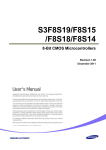
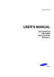
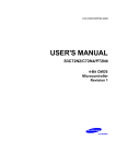
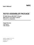
S3C72P9/P72P9 (Preliminary Spec)
DEVELOPMENT TOOLS
Table 17-3. Sub-Clock Selection Settings for TB72P9
Sub Clock Setting
XTI
MDS
XTAL
Operating Mode
Comments
Set the XTI switch to "MDS"
when the target board is
connected to the
SMDS2/SMDS2+.
EVA Chip
S3E72P0
XT IN
XT OUT
No Connection
100 Pin Connector
SMDS2/SMDS2+
Set the XTI switch to "TAL"
when the target board is used
as a standalone unit, and is
not connected to the
SMDS2/SMDS2+.
XTI
MDS
XTAL
EVA Chip
S3E72P0
XT IN
XT OUT
XTAL
Target Board
Table 17-4. Using Single Header Pins as the Input Path for External Trigger Sources
Target Board Part
Comments
External
Triggers
Connector from
External Trigger
Sources of the
Application System
Ch1
Ch2
You can connect an external trigger source to one of the two external
trigger channels (CH1 or CH2) for the SMDS2+ breakpoint and trace
functions.
IDLE LED
This LED is ON when the evaluation chip (S3E72P0) is in idle mode.
STOP LED
This LED is ON when the evaluation chip (S3E72P0) is in stop mode.
17-5