1
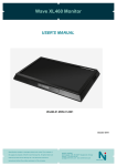
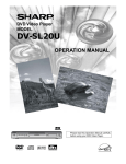
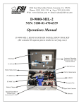
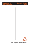
Building 16 Roof Safety Assessment Roof Safety Survey GENERAL INFORMATION CAMPUS: BUILDING: DESCRIPTION: RISK ASSESSMENT # : ROOF ACCESS: 1) Main 2) Secondary 3) Via Building 17 4) Awning SIGNAGE: COMPLIANCE PLATES: MARKED SAFE AREAS: ROOFING SYSTEM: Wollongong Campus Library (16) Original flat concrete roof surrounded by handrail and parapet. More recent extentions on the northern and eastern sides have a metal roof with anchor points but no parapet or handrails. UOW01585 Multiple access points from stairwells in building 16 & 17 Access via Stair 6 Access via Stair 5 Access from adjoining roof Access via portable ladder on North west corner near cafe to connect to lifelines. Ladder brackets installed Danger - No Access to Roof without a Buildings and Grounds Roof Access UOW Permit to work; Caution - Trip Hazard. No compliance plates - 10 anchor points on eastern awning, two on either end of the upper northern awning, six on the lower northern awning and two on the western awning Within handrailed and marked painted areas TYPICAL ANCHORS Travel8 Static Line HEIGHT OF BUILDING: PITCH: ROOF CONSTRUCTION: STRUCTURAL INTEGRITY: 3 storey Flat Concrete / Metal balonies Uneven surfaces. Sound structure VEGETATION: Nil ADJOINING ROOFES: IT Resource Centre (17) SERVICES: Gutters A/C Units Exhaust Fans Ducts Roof Ventilators Fume Cupboards Telco Towers Yes Yes Yes Yes Yes No 2 Satellite Dishes Antenna Skylights Domes Glass Skylights Pipework Cooling Tower Yes Yes No No Yes Yes EXISTING SAFETY ITEMS: Horizontal Lifelines Anchor Points Vertical Lifelines Yes Yes No Handrail Walkway Parapets Yes No Yes WORK ACTIVITY DETAILS: Clean Gutters / Routine Mainten Yes Service A/C Plant Yes Cooling Tower Maintenance Yes Note: Before commencing any work obtain Roof Permit from Facilities Management Division HRD-WHS-REF-445.2 2014 May Frequency Every 3 Months Monthly Monthly Building 16 Roof Safety Assessment Roof Safety Survey RISK ASSESSMENT BUILDING 16 Risk Assessment / Task Location Note: The hazards identified do not include hazards that related to specific work tasks. These should be identified in the Safe Work Method Statement (SWMS) of the contractor. Risk Assessment & Control Measures Hazard Identification What is the Activity/Service Item What are the potential Hazards Access From Bldg 16 Stairwell Negligible risk Access Concrete Roof within Handrail Area Trip Hazards on Roof Area from pipework, air-conditioning services, electrical trays and steps. Negligible risk of falling if worker stays within handrail Access Color Bond Roof outside Handrail Area Access to plantroom Roof Access to Roof General - Working on Roof Antenna Maintenance A/C Maintenance Cleaning of Drains on Concrete Roof Cleaning of Gutters on Concrete Roof Maintenance of Telco Towers General General General What is the Risk Level Negligible Trip Hazard & Falling Medium Fire Stair Access Negligible risk Caution when crossing services, small section of Stairs Additional Signage and demarcation Anchor Points Harness to Anchor Points None Ensure SWMS developed is followed by Contractors Unauthorised access All access points to roof are locked and made secure so are not accessable by unauthorised Medium persons; signage Refer to SWMS of contractor Medium Currently not near a roof edge Risk Assessment and Roof Safety Survey Continuing Leaves & Branches, Contractors rubbish Medium Maintenance Maintenance/cleaning Adequate signage Refer to RF website: required and RF hazard High www.rfnsa.com.au/nsa/index.cgi demarkation Negligible risk Low Trip Hazard & Falling Medium Trip Hazard - Horizontal Lifeline or Anchor Points Environmental Hazards - Spiders, Wasps, and other insects Weather - Hot Conditions Negligible risk Anchor Points Harness to Anchor Points Medium Signage & System is visible Appropriate PPE and insect Medium repellent and Pest control as required Weather Trips/Slips - Wet Roofs Ensure SWMS developed is followed by Contractors Handrail Provided The Telco Contractors have their Medium own controls Refer to SWMS of Telco Medium General Describe what can be List any Control Measures already done to eliminate risk or Implemented reduce the harm Medium High Falls from climbing. While on roof there is no protection from fall. Risk Control No access to Colorbond roof in wet weather. If accessing concrete roof, be careful while walking over slippery services Medium Thermal Comfort Guidelines HRD-WHS-REF-445.2 2014 May Telco Responsibility Be aware of location of horizontal lifeline & anchor points On-going pest control measures No access to Colorbond roof in wet weather. Only access roof in rain when necessary. Be careful working around slippery services. Use sun cream, hats and remain hydrated and take appropriate breaks Building 16 Roof Safety Assessment Reference Documentation Legislation NSW Work Health and Safety Regulation 2011 Part 4.4 Falls Public Health (Microbial Control) Regulation 2000 Australian Standards AS 1657 - 2013 : Fixed platforms, walkways, stairways and ladders - Design, construction and installation AS 1891.1 - 2007 : Industrial fall-arrest systems and devices - Harnesses and ancillary equipment AS 1891.2 - 2001 : Industrial fall-arrest systems and devices - Horizontal lifeline and rail systems AS 1891.3 - 1997 : Industrial fall-arrest systems and devices - Fall-arrest devices AS 1891.4 - 2009 : Industrial fall-arrest systems and devices - Selection, use and maintenance AS 2210.1 - 2010 : Safety, protective and occupational footwear - Guide to selection, care and use AS 3666- 2011 : Air-handling & Water Systems for Buildings - Microbial Control AS 4994.1 - 2009 : Temporary edge protection - General requirements AS 4994.2 - 2009 : Temporary edge protection - Roof edge protection - Installation and dismantling AS 5532 - 2013 : Manufacturing requirements for single-point anchor device used for harness-based work at height Code of Practice Safe Work Australia - Managing the Risk of Falls at Workplaces NSW Health Department Code of Practice for the Control of Legionnaires' Disease UOW Documentation Managing the Risk of Falls Guidelines Thermal Comfort Guidelines UOW Roof Access Permit UOW Roof Access Certificate Other SALA - Fall Arrest and Height Safety Systems - Fall Protection Manual WorkCover - Safe Working at Heights Guide 2006 MCF Fact Sheets - Working safely around Radiofrequency (RF) Transmitters Radio Frequency National Site Archive - http://www.rfnsa.com.au/nsa/index.cgi HRD-WHS-REF-445.2 2014 May Building 16 Roof Safety Assessment Campus Map L - Location of ladder bracket A - Location of Access to roof - Location of anchor point _______ Horizontal Lifeline HRD-WHS-REF-445.2 2014 May Building 16 Roof Safety Assessment Looking East from main access point Small Plantroom beside access stairs Looking North from main access point on western side of building Looking North onto balcony on western side of building Looking North onto balcony on northern side of building Pipework on roof HRD-WHS-REF-445.2 2014 May Building 16 Roof Safety Assessment Position of anchor points on North west corner Cooling towers in centre of building and secondary access stairs Airconditioning unit on northern side of building Library - Eastern balcony looking north Ladder down to courtyard awning HRD-WHS-REF-445.2 2014 May GUIDE LINE ONLY THIS OPERATION MANUAL SHOULD BE CONSIDERED A GUIDE ONLY. ALL PERSONS USING THE EQUIPMENT LISTED IN THIS MANUAL MUST BE COMPETENTLY TRAINED. “THE INSTALLER” INSTALLS SYSTEMS ONLY AND DOES NOT MANUFACTURE THE SYSTEMS. END USERS TO ENQUIRE WITH “THE MANUFACTURER” (BULLIVANTS ) AT THEIR OWN DISCRETION. ALWAYS FOLLOW MANUFACTURERS INSTRUCTIONS. TYPICAL ANCHORS USER MANUAL TRAVEL 8 PERMANENT STATIC LINE SYSTEM The Travel 8 Permanent Static Line is a proprietary fall arrest system suitable for multiple users. The system provides continuous attachment and effective fall protection across roof surfaces and other elevated areas to which safe access is required. The system incorporates low profile, high quality componentry which can be used in horizontal, vertical and overhead applications using the required system traveller. > Advanced energy absorbing and multi user capability > Smooth intermediate pass through system using the Pilot Traveller > Various adaptable mounting facilities > Simple installation using modular componentry > Low profile system blends in with surroundings THIS USER Manual must be read and understood prior to use of this sytem www.sayfa.com.au/travel8 www.sayfa.com.au/travel8 1 IMPORTANT USAGE & MAINTENANCE INSTRUCTIONS Must be read prior to use 1.Prior to use, ensure all operating procedures have been read and understood. 2.This system is only to be used by competent persons who have experience and training in the safe use of the system and associated equipment. 3.Ensure all associated risks are identified and controlled prior to use of this system. 4.This system will require periodical inspection and maintenance by a qualified height safety inspector. The system must not be used if the current date exceeds the due service date. 5.A rescue plan must be devised and be ready to be implemented prior to usage of this system. 6.Authorisation to enter any risk area must be obtained from the person in control of the workplace prior to accessing. 7.Only approved full body harness, lanyards and fall arrest device with energy absorber certified to Australian Standard AS/NZS 1891, to be used with this system. 8.Visually inspect the system for damage prior to use. System must not be used if there is any deterioration or deformation of any components or structure to which the system is attached. 9.In the event of a fall and/or damage to the system, usage must be prohibited until the system has been fully inspected and recertified by a qualified height safety equipment inspector. 10.Applicable Australian Standards, OHS Acts and Regulations, Codes of Practice and Guidelines must be read and adhered to prior to use of this system. Failure to follow all warnings, useage and maintenance instructions may result in serious injury or death. www.sayfa.com.au/travel8 2 Call\ 1300 301 755 Call\ 1300 301 755 CONTENTS IMPORTANT USEAGE AND MAINTENANCE INSTRUCTIONS 03 SYSTEM KNOWLEDGE 04 SYSTEM LIMITATIONS 05 PROCEDURE FOR SAFE USE OF THE SYSTEM/ EQUIPMENT 06 SYSTEM MAINTENANCE AND INSPECTION REQUIREMENTS 08 SYSTEM CONFIGURATIONS 09 TECHNICAL SPECIFICATIONS 11 WARRANTY INFORMATION 12 Failure to follow all warnings, useage and maintenance instructions may result in serious injury or death. www.sayfa.com.au/travel8 3 SYSTEM KNOWLEDGE SYSTEM KNOWLEDGE it is important to know and understand the system components, it is important to know understand configuration and usesand of the system. the system components, configuration and uses of the system. SL1 \ TOP MOUNT STATIC LINE CONFIGURATION 1 2 7 1 3 6 5 1 2 3 4 4 END STANCHION - SL203 ENERGY ABSORBER - SL 215 INTERMEDIATE - SL 209.10 CORNER - SL 223 This provides a secure termination anchorage for the cable. Designed to deploy under excessive load limiting forces on the system and operator. To support the cable and reduce forces on the end stanchions. Supports a change in the direction of the cable. 5 6 7 LINE TENSIONER - SL 218 ANCHORAGE CABLE - SL 230 SYSTEM TRAVELLER - SL 227 Ensures line tension can be adjusted after installation and during maintenance. Stainless steel cable to which the system traveller attaches. The device to which the operator’s harness/lanyard attaches during use. This unit attaches to the anchorage cable. www.sayfa.com.au/travel8 4 Call\ 1300 301 755 Call\ 1300 301 755 SYSTEM LIMITATIONS Only to be used by competent persons with proof of training by registered training organisation in height safety and fall arrest systems. Only Australian Standards certified harness gear to be used. Only to be used with approved system traveller. 30° Not to be used on slopes exceeding 30° Do not exceed allowed number of persons per span. Do not tamper with system components. Not to be used for tethering or lifting machinery System must be periodically checked by qualified height safety equipment inspector. www.sayfa.com.au/travel8 5 PROCEDURE FOR SAFE USE OF THE TRAVEL8 SYSTEM PRIOR TO USE Ensure all workplace OH&S requirements are identified and understood. A risk assessment with a safe work method procedure must be completed and approved by management. Ensure the limitations of this system have been read, understood and implemented prior to use of this system. Check the system has been serviced/recertified in accordance with Australian Standards and manufacturer recommendations. System must not be used if due service date exceeds current date. Line tension must be sufficient so that the line is not resting on the roofdeck. Tensioning of the line must be only done by a competent person. Ensure all fixings, fittings and attachment hardware are secured. Any tightening and replacement of attachment hardware must be done by a competent person. Any damage/deterioration of the structure must be reported and the system decommissioned until analysed and recertified by a competent person. Check the energy absorber for signs of deployment. Should the red indicator be visible, this indicates the system has sustained an abnormal load. The system must not be used until checked and recertified by a competent person. www.sayfa.com.au/travel8 6 Call\ 1300 301 755 Call\ 1300 301 755 PROCEDURE FOR SAFE USE OF THE TRAVEL8 STATIC LINE SYSTEM STEP 1 Ensure a full body harness and suitable rope line is used with this system! arness Gear must be certified to Australian Standards H AS/NZ 1981 Travel 8 system must be used with a tear-web lanyard conected to rear dorsal ring of harness. Ensure Harness Gear servicibility dates are current. STEP 2 Only the Pilot shuttle must be used with Travel 8 static line system! STEP 3 Approach static line system from a ‘Safe Zone’ i.e. no risk of fall or injury. STEP 4 Pilot shuttle must be fitted correctly to Travel 8 static line system! www.sayfa.com.au/travel8 7 PROCEDURE FOR SAFE USE OF THE TRAVEL8 STATIC LINE SYSTEM STEP 4A Remove karabiner. STEP 4B Slide latch to open position. STEP 4C Place onto cable. STEP 4D Flip shuttle over and slide latch to closed position. www.sayfa.com.au/travel8 8 Call\ 1300 301 755 Call\ 1300 301 755 PROCEDURE FOR SAFE USE OF THE TRAVEL8 STATIC LINE SYSTEM STEP 4E Insert karabiner. Ensure Shuttle is securely attached to cable and Karabiner screw gate is closed and locked. STEP 4F Shuttle is ready to use! STEP 5 Attach lanyard to Pilot shuttle karabiner. R ope line must be attached to harness via tear-web energy absorbing lanyard. STEP 6 Adjust rope line to a safe and comfortable distance to traverse roof. Maintain close proximity to static line for optimum safety and shuttle traversing. www.sayfa.com.au/travel8 9 PROCEDURE FOR SAFE USE OF THE TRAVEL8 STATIC LINE SYSTEM STEP 7 Once in line with area to be accessed, payout rope line evenly toward roof edge. Ensure NO slack rope line! STEP 8 Ensure there is NO possibility of pendulum when at fall edge! User must remain in restraint at all times limiting access beyond the fall edge ie: NO slack rope line! STEP 9 Use diversion anchorage to access corners or possible pendulum areas. Attach rope line to diversion anchorage using Karabiner. STEP 10 Disconnecting from the system – return to Static Line keeping rope line tensioned. www.sayfa.com.au/travel8 10 Ensure there is no risk of a fall at detachment location! Call\ 1300 301 755 Call\ 1300 301 755 PROCEDURE FOR SAFE USE OF THE TRAVEL8 STATIC LINE SYSTEM STEP 11 Disconnect Pilot shuttle. STEP 12 Harness equipment must be stored in carry bag provided and kept in a dry environment. Any damage to Harness Gear or Static Line system during use, MUST be reported to the workplace manager. STEP 13 Proceed safely back to the roof access point. www.sayfa.com.au/travel8 11 SYSTEM MAINTENANCE SYSTEM MAINTENENANCE AND INSPECTION REQUIREMENTS & INSPECTION REQUIREMENTS Componentry/System in good working order and suitable for use until next due checking date. Componentry/System requires attention but is still suitable for use. Identify recertification works with suitable signage. Arrange for recertification using qualified system installer. Componentry/System is not safe for use. Prohibit use of system and attach suitable ‘out of service’ signage. Arrange for recertification using qualified system. installer. Component Inspection criteria End stanchion Code: sl203 Unit to structure secure All fixings secure No evidence of roof leaks No visible damage to unit/structure Other: Energy absorber Code: sl215 Secure attachment to end stanchion Lock in pin circlip secure No ‘red’ excessive load indicator visible No visible damage to unit/structure Other: Intermediate Code: sl209 Unit to structure secure Cable support brackets secure No evidence of roof leaks No visible damage to unit/structure Other: Corner Code: sl223 Unit to structure secure Cable support brackets secure All fixings secure No evidence of roof leaks No visible damage to unit/structure Other: www.sayfa.com.au/travel8 12 Call\ 1300 301 755 Call\ 1300 301 755 THIS SYSTEM MUST ONLY BE MAINTAINED BY A CERTIFIED HEIGHT SAFETY EQUIPMENT INSPECTOR TRAINED IN THE SAFE USE & MAINTENANCE OF THIS SYSTEM. Component Inspection criteria Line Tensioner Code: SL213.10 Secure attachment to end stanchion Lock in pin circlip secure Tension indicator disc can be rotated manually Swaged cable termination secure, no evidence of slipping All locknuts and fixings secure No visible damage to unit/structure Other: Anchorage Cable Code: SL230 No cuts or frays to cable Cable correctly tensioned ie. not touching the roofdeck Securely attached to end stanchions No visible damage Other: System Traveller Code: SL227 Slide latch operates freely Gap between tongue & shuttle inner casing when closed and latched with karabiner 6mm max Karabiner fits securely when slide latch closed Karabiner gate lock device operates securely No visible damage to unit Other: Data Plate Code: SAY_Travel 8 Sticker_FNL_O.pdf 11/9/09 Data plate attached nearby system 1:54:19 PM C M Y CM MY CY All relevant data completed as well as record of maintenance CMY K Other: www.sayfa.com.au/travel8 13 SYSTEM CONFIGURATIONS SYSTEM KNOWLEDGE Typical configurations it is important to know and understand the system components, configuration and uses of the system. SL1 \ Top Mount Static Line System SL 2 \ CONCRETE/STEEL STRUCTuRE MOUNT STATIC LINE SYSTEM SL3 \ STTEL PURLIN Mount Static Line System SL4 \ TIMBER Mount Static Line System Failure to follow all warnings, useage and maintenance instructions may result in serious injury or death. www.sayfa.com.au/travel8 14 Call\ 1300 301 755 Call\ 1300 301 755 TECHNICAL SPECIFICATIONS TRAVEL8 PERMANENT STATIC LINE SYSTEM ® The Travel 8 Permanent Static Line is a proprietary fall arrest system suitable for multiple users. The system provides continuous attachment and effective fall protection across roof surfaces and other elevated areas to which safe access is required. The system incorporates low profile, high quality componentry which can be used in horizontal, vertical and overhead applications using the required system traveller. > > > > > Advanced energy absorbing ability and multi user capability Smooth intermediate pass through system using the Pilot Traveller Various adaptable mounting facilities Simple installation using standard componentry Low profile system blends in with surroundings Specification Code Travel 8 Static Line System (SL1) – Top Mount Travel 8 Static Line System (SL2) – Concrete Mount Travel 8 Static Line System (SL3) – Purlin Mount www.sayfa.com.au/travel8 15 TECHNICAL SPECIFICATIONS Specification Summary Supply and install the Travel 8 Static Line System as per supplier, Sayfa Systems, recommendations. System to incorporate applicable low impact end anchorages, intermediate line support anchorages, corner modules, line tensioners and shock absorption componentry as specified by the manufacturer. System to provide ‘pass through’ traveller action over intermediate line support anchorages ensuring freedom of movement and constant operator attachment to the system. System functions in horizontal, vertical and overhead applications using the applicable line traveller. (Refer instruction manual.) Fixings Metal fixing – M14 stainless steel stud fixing Concrete fixing – M12 mechanical concrete anchor Metal roof deck fixing – 8mm construction grade Bulbtite rivets (Refer instruction manual.) System Applications >> Periodical maintenance of gutters and roof edges >> Provides high level safety for workmen and maintenance personnel >> Access to roof mounted plant and equipment >> Effective fall protection over brittle roof surfaces, skylights, glass, slate and asbestos roof decks Testing Testing and performance based on requirements of Australian Standards AS/NZS1891.2:2001 and AS/NZS1891.4:2009. Following a dynamic load applied to the system, resultant reduced loads (due to energy absorbing characteristics) as follows: > Intermediate – 6.48kN > End stanchion – 8.56kN Technical Data Material 316 stainless steel profiled plate assembly including: End stanchions, intermediates, corners, cable and connection devices. Dimensions Attachment Cable – 8mm (7 x 7 strand) Cable Height off structure – 125mm to 150mm Intermediate Spacing – 6.0m to 8.0m intervals Cable Tension 800 N – set with self-tensioning device Working Load Limit User Weight Limit – 120kg (user & equipment) >> Up to 4 users per line, determined by intermediate spacing and roof pitch >> Maximum roof pitch – 30º >> Support structure integrity, suitability and fixing method to be assessed and determined by a competent person prior to installation >> Travel 8 Static Line System must only be used with the approved Pilot Traveller device and harness system with energy absorber as per AS/NZS1891.1:2009 and AS/NZS1891.4:2009 Compliance Travel 8 Static Line System is designed and manufactured generally in accordance with requirements of Australian Standards AS/NZS1891.2:2001 and AS/NZS1891.4:2009 and relevant statutory OHS Codes of Practice/Guidelines. Product Warranty 3 years from date of purchase subject to installation in accordance with manufacturer’s specifications and recommendations. Inspection and Maintenance Inspection and certification every 12 months by competent person in accordance with manufacturer’s specifications and requirements of Australian Standard AS/NZS1891.4:2009 Section (9). (Refer instruction manual.) Important Note Failure to supply and/or install proprietary product in accordance with above standards and codes, specifications and instructions voids complete system certification and/or warranty. Technical Support Sayfa Systems T \ 1300 301 755 F \ 1300 881 092 E \ [email protected] W \ www.sayfa.com.au Designed and manufactured by Sayfa Systems © Sayfa Systems. All rights reserved. Product designs and brand names registered. Product information and images for general guidance and illustrative purposes. WARRANTY INFORMATION TRAVEL8 STATIC LINE SYSTEM WARRANTY period on this system - 3 years from date of purchase WARRANTY TERMS AND CONDITIONS Should you have a warranty claim as a result of a defect the following procedure must be followed: Identify the following information: • The product/system name and code number • The date of purchase/installation • The name of the installation company • The installation identification number • A description of the defect/warranty claim Forward the above information to www.travel8-staticline/warranty or contact technical helpline:1300 301 755. WARRANTY TERMS & CONDITIONS • All warranty claims must be made in writing within 14 days of the appearance of the defect. • Incorrect installation or work done by a non accredited Travel8 system installer will void all warranty rights. • Systems/components that have not been maintained in accordance with manufacturer’s/ legislative requirements will void all warranty rights. • Systems used by incompetent personnel or use with non compatible accessories ie. harness gear, lanyards, travellers, fall arrestors etc., will void all warranty/rights. • Systems/components used for purposes other than their intended use will void all warranty claims. • General wear and tear is expected and will depend on the frequency of use and is not covered by the manufacturer’s warranty. NEVER HAS SAFETY IN THE WORKPLACE HAD A HIGHER PRIORITY www.sayfa.com.au/travel8 17